
Tailoring the Local Design of Deep Water Composite Risers to Minimise Structural Weight


1
Department of Engineering, Lancaster University, Bailrigg, Lancaster LA1 4YR, UK
2
Standards Organisation of Nigeria (SON), 52 Lome Crescent, Wuse Zone 7, Abuja 900287, Nigeria
3
Department of Production Engineering, Trident Energy, Wilton Road, London SW1V 1JZ, UK
4
Department of Civil Engineering, Universiti Teknologi PETRONAS, Seri Iskander 32610, Malaysia
5
Department of Civil Engineering, Ahmadu Bello University, Zaria 810107, Nigeria
6
School of Civil and Architectural Engineering, Shandong University of Technology, Zibo 255000, China
*
Authors to whom correspondence should be addressed.
J. Compos. Sci. 2022, 6(4), 103; https://0-doi-org.brum.beds.ac.uk/10.3390/jcs6040103
Submission received: 17 December 2021
/
Revised: 20 March 2022
/
Accepted: 22 March 2022
/
Published: 26 March 2022
(This article belongs to the Special Issue Carbon Fiber Composites, Volume II)
Abstract
:Following the rising technological advancements on composite marine structures, there is a corresponding surge in the demand for its deployment as ocean engineering applications. The push for exploration activities in deep waters necessitates the need for composite marine structures to reduce structural payload and lessen weights/loads on platform decks. This gain is achieved by its high strength–stiffness modulus and light-in-weight attributes, enabling easier marine/offshore operations. Thus, the development of composite marine risers considers critical composite characteristics to optimize marine risers’ design. Hence, an in-depth study on composite production risers (CPR) is quite pertinent in applying composite materials to deep water applications. Two riser sections of 3 m and 5 m were investigated under a 2030 m water depth environment to minimise structural weight. ANSYS Composites ACP was utilized for the CPR’s finite element model (FEM) under different load conditions. The choice of the material, the fibre orientation, and the lay-up configurations utilised in the modelling technique have been reported. In addition, the behaviour of the composite risers’ layers under four loadings has been investigated under marine conditions. Recommendations were made for the composite tubular structure. Results on stresses and weight savings were obtained from different composite riser configurations. The recommended composite riser design that showed the best performance is AS4/PEEK utilising PEEK liner, however more work is suggested using global design loadings on the CPR.
1. Introduction
Presently, the global demand for oil/gas products has induced the incremental need for rapid technological advances in novel materials [1,2,3,4,5,6]. Such an advancement in composite materials has been induced by the increased application of marine composites [7,8] and the shift in the fluid-transfer operations from shallow water to deep water [9,10,11,12,13]. This trend is particularly evident in the developments achieved on deep water composite risers [14,15,16,17,18]. However, the deep water operations require more riser lengths, resulting in a considerable increment in weight. The number of the risers needed depends on the type of offshore structure, the type of risers required, the riser configuration considered, and the water depth [19,20,21,22]. Improving the riser technology is a challenge, as such composite materials are recommended as an excellent choice. The composites proffer superior positives, which can be utilised. These benefits include weight gains, high strength attributes, high fatigue resistance, low bending stiffness, high corrosion resistance, and light weight [23,24,25,26,27,28,29,30]. Due to the exciting features of composite materials, there is growth in the application and recent research on offshore composites, marine composites, and composite risers [31,32,33,34,35,36,37,38,39,40]. However, recent studies on these structures reflect the necessity to design composite risers by considering the loadings including environmental loads [41,42,43,44,45,46,47,48]. A typical composite riser pipe technology called M-pipe developed by Magma is shown in Figure 1.
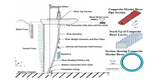
Composite marine risers have been considered for deployment, utilisation in deep waters, and as composite production risers [49,50,51,52,53,54,55,56,57,58]. These studies reflect different novel approaches on composite riser design and analysis. These studies also underpin the stress deformations alongside the buckling attributes of the structure. Research on composite risers stems from previous studies on shells, composite tubulars, and cylindrical structures [34,59,60,61,62,63,64,65] as seen in current related standards [66,67,68,69,70,71]. The first successful deployment of composite risers was a joint for composite risers installed on the Heidrun offshore platform [2,23,72,73,74]. Subsequently, the design evolution of composite risers has been achieved progressively for over 30 years [2,14,15,16,17,18,23]. The solutions on weight reduction and efficiency improvement were conducted using fibre reinforcements at an angle of +/− 55° by Doris Engineering [15]. The authors presented their design that assumed the fibres in each layer were load-bearing, according to netting theory [25,74,75,76,77,78]. However, there were no stresses in the transverse direction, and that resulted in an efficient angle of +/− 54.7°. This study helped in the application of the filament winding technique on composite risers [60,61], design of prototypes [17,38,79,80], experimental tests [81,82,83,84,85,86], and the global–local design [42,43,44,45,46,87,88,89,90,91] and safety-reliability assessments [92,93,94,95]. Similarly, the developments led to advances in end-fitting designs, the metal–composite interface (MCI), debonding, delamination, and composite riser joint design. In a nutshell, more studies focused on the strength performance, buckling, material choice, and fibre orientation and optimization of composite risers [96,97,98,99,100,101,102,103,104,105]. The technology for composite risers is not fully enabled for full deployment. It is currently used as a hybrid riser system, since it is a supporting or enabling technology which implies that it requires more investigation for its qualification for deep water applications [106]. Jha et al. [107] presented various optimised hybrid composite pipe solutions by appreciating the variety of composite pipe design concepts and addressing key concerns bearing on both the manufacturing and customer acceptability point of view. Tan et al. [44] investigated 1500 m composite risers by utilising coupling analysis in both global and local analysis, whereby the authors found that titanium liner had lesser root mean square (RMS) strains than aluminium liner. However, the technology challenges for composite risers are based on the weight of risers limiting their lengths and motion of offshore operation facilities when applied further into deep waters [35,36,37,47,89]. An illustration of the composite marine risers with loads acting on the structure is represented in Figure 2.
Another engineering challenge is the qualification of lengthy CPRs, as more novel optimized designs are required. Some discussions on optimization were presented in different literature [97,98,99,100,101,102,103,104]. Harte et al. [101,102] carried out some optimisation techniques on composite pipelines using a safety factor of 4.5. The authors observed that to lessen the composite pipeline’s weight, optimisation had to be conducted around the composite pipeline joint (CPJ). They also found a significant reduction in the peak stresses and the weight of the pipeline. Composite riser designs evolved into optimized designs as presented with a prototype using bonded and unbonded armours [108]. Amaechi et al. [87,88] introduced a novel numerical approach for the 18-layered composite riser structure using the ANSYS Composites ACP module and presented some safety factors on the structure under six unique loading cases and concluded that the finite element model was recommended for the validated design. Wang et al. [45,46,47,48,89] investigated global and local design of composite risers using ANSYS APDL and presented stress profiles for some configurations used to investigate the reduction in the structural weight under critical load cases. In addition, this technique considered the manual tailoring effects by using multiple variables for less, which was later optimised using surrogate-assisted evolutionary algorithm (SAEA) optimisation [104], which led to a weight reduction of 25% from the designs. Singh and Ahmad [91] presented a numerical design of carbon epoxy composite production risers carried out using ABAQUS AQUA in random water waves and investigated the global and local design using steel liner by considering the limit state failure criteria and validated the study with a composite riser model by Kim [108]. Other numerical methods deployed include homogenization of the multilayered composite offshore production risers [109,110]. In another study on the failure analysis of composite cylindrical structure by Bhavya et al. [111], the failure criteria applied were the Tsai-Wui and the maximum normal stress theories. They studied the influence of diameter to thickness ratio under pressure loads on four-layered and six-layered cylindrical structures using the finite element model.
The tailored local design on composite risers for deep water environments to minimise the structural weight is presented herein. In this paper, Section 1 presents the introduction, Section 2 presents the analytical model, Section 3 presents the numerical model, Section 4 presents the results and discussion, while Section 5 presents the concluding remarks. The study will aid the development of the global design of composite risers under different configurations for riser installation and deployment.
2. Analytical Model
2.1. Stress and Deformation
Consider a thick laminate of the composite riser formed by more plies for the composite laminas. In theory, the laminas are made up of two components, called M and N, where M is the representative volume of the total composite riser body and N is the number of fibre orientations. The material is considered in both the cylindrical coordinate system and cartesian coordinate system. The z-axis lies perpendicular to the plane of the laminae as given in Figure 3. With regards the effective macroscale of the composite material, the stress and strain definitions for the material are respectively given by Equations (1) and (2) [91]:
Let us consider the point where both the stress and strain values on each of the composite riser lamina are constant. At this point, integrate the set of equations in Equations (1) and (2) to obtain Equations (3) and (4) [91]:
In this research, the 18 layers of the composite riser under internal pressure load are represented by N = 18. The material model of the cylindrical composite riser is depicted by a cylindrical coordinate system, where r represents the radial, ϴ is the hoop, and z is the axial coordinate. The strains and stresses in cylindrical riser pipe do not depend on ϴ when it is asymmetrically loaded.
Both the radial displacement and axial displacements are independent on the radial coordinates (r) and axial coordinates (z), respectively. Thus, the displacement field for the composite riser can be enunciated in Equation (5), where ur, uϴ, and uz are the displacements for the radial, hoop and axial directions, respectively.
where the reference frames are denoted by MPCS (material principal coordinate system) and CPCS (cylindrical coordinate system), as in Figure 3.
The characteristic effects of both twist (shear twist) and Poisson ratio are considered for each lamina of the anisotropic material. For the N-layered cylindrical composite riser, 2 N + 2 unknown constants are to be obtained for each of the layers. This is determined based on stress–strain relationship, stress–displacement relationship, and the boundary conditions for the system.
2.2. Elastic Solution of Stresses
The classical laminate theory has been utilised in the design approach for the CPR. This is used to evaluate the stack-up and laminate properties by considering the laminate forces. The composite riser is considered as a shell model with nodal deformations. Adequate bonding of the layers is necessary to ensure less stress on the laminates. The material properties for the composite riser are provided for each layer with different thickness, as described in Section 3. The mechanical behaviour of the composite riser is dependent on the material attributes, the orientation angle of the lay-ups, and the laminate thicknesses. Although risers are slender structures, we design the composite riser as a shell with characteristic values. These are given as the in-plane laminate stiffness and flexural laminate stiffness, respectively. Under operational conditions, we can formulate the boundary conditions for the composite riser.
Consider the three-dimensional material properties for multilayered composite materials, having engineering constants where the matrix elements for the material modulus are given by Cij (i, j = x, y, z) and Gii (i = x, y, z). Assume transverse isotropy for the unknown equivalent characteristics along the y-z axis of the unidirectional composite material(s). The denotation for the engineering constant is Ei (i = x, y, z), the material’s principal axis along the fibre direction is x, and the material’s principal axis along the transverse direction is y; thus the illustration in Figure 3.
2.3. Constitutive Equation
For the local design of the composite risers, consider a composite hose tube acted upon by internal pressure; thus, it will be subject to the orientation of the composite laminate and the winding angle . However, when there is axisymmetric loading acting on the composite tube, such as internal pressure loads, the relationship for the stresses and strains becomes dependent on , such that Equation (6) holds, where u, represent the displacement vector, stress tensor, and strain tensor, respectively.
There will be a resultant force that acts laterally on the material of the composite hose tube or composite riser pipe when it is subjected to constant internal pressure. That resultant force is proportional to the constant tension force which produces a constant axial strain. Considering the stress analysis of composite tubes and composite risers, it is determined based on the thickness of the wall. For the present study, the stress analysis of thick-walled composite is applied. Details on the numerical modelling approach are discussed in Section 3. The results of this analytical model were computed and compared with the numerical model as presented in Section 4.1. See analytical formulations in [112].
3. Numerical Model
3.1. The Model Design
The model designed for the CPR in this research is the local design investigated utilising the ANSYS workbench. It was used to design the riser by considering it as a multilayered structure. A comparative study between the tailored model and the conventional model of the composite riser was conducted in the local design. Optimisation and global design were also carried out but not detailed in the present study. The particulars for the CPR are detailed in Table 1. This design was carried out for a CPR operating in a water depth of 2030 m. The effective weight of the riser was taken into account in the riser’s tension computation depending on the wall thickness(es) utilised. The extreme cases for the burst analysis are not included, and the tension of the riser was designed differently. In the design of the composite riser, three approaches were considered: numerical design, conventional design, and analytical design. The constitutive model for the composite riser was derived using the analytical design. The traditional design of composites is based on orthogonal design, in which laminate reinforcements are exclusively positioned along the hoop and axial fibre directions. In this approach, the composite risers’ plies are oriented similarly, wherein both the axial and hoop layers are oriented at 0° and 90°, respectively.
The composite riser design was analysed by applying maximal stress distribution as the failure criteria. This was on each composite lamina (layer), as the design targets the implementation in deep waters. The effects of the fibre orientation and material combinations were investigated in in-plane shear, transverse, and fibre directions. The distribution was formulated under four different load cases. In order to analyse the stresses in composite riser body of the composite materials, we used the finite element model (FEM) software, utilising ANSYS ACP (versions R18.2 and R1 2021) [113,114]. Two riser sections of 3 m and 5 m were applied in the local design, and the consequence of the burst case was validated numerically. The riser design was considered for application in deep waters of about 2030 m depth. The water depth is vital for global design, which is not conducted herein; however, further considerations should include the global design of the composite riser.
3.2. Material Properties
The material properties considered in this local design are used to model the composite riser. The setup for the material model includes the materials for the matrix, the fibre reinforcements, and the liners considered in the design, as presented in Table 2 and Table 3. The scientific basis for selecting parameters in Table 2 and Table 3 is based on specifications recommended in the ABS industry standard [70]. The design considerations for the conditions for the composite production riser (CPR) are pressure resistance, fluid tightness, and fluid capillarity. As such, the choice of design materials for the CPR, particularly the liner, includes the prevention of fluid leakage. On that note, the key considerations are not only the choice of the fibre reinforcements and the matrix but also the materials selection. Hence, the materials selected must be able to withstand different mechanical loadings and different environmental conditions, as specified in DNV and ABS standards [66,67,68,69,70]. Considering a composite marine riser that is fully operational, high pressure conditions must be considered. The elastic constants considered in the material properties were utilised based on the theory applied by Sun and Li [115]. Based on the classical laminate theory, the laminates for the composite riser were efficiently analysed. The walls of this composite marine riser are considered as thick laminates. Thus, higher-order mathematical theories (HOMT) with three-dimensional (3D) material characteristics are required. The homogenous solid was used for a characteristic lengthwise span of the CPR. Due to deformation in the global composite riser, there is comparative deformation when compared to composite materials of shorter lengths. Considering the classical laminate theory (CLT), constants on the in-plane effective properties of the composite body can be generated. Thus, there must be three-dimensional effective properties. The material properties of the composite riser depend on time, static loads (tension and pressure), and environmental conditions (such as temperature, chemicals, or water). These properties were obtained via several validated scientific studies, as in referenced publications and technical reports [116,117,118,119]. These selected composite materials were also validated for the composite riser model, using verified modelling methods [3,4,5,87,88,89,90,91].
3.3. Stack-Up Sequence
Modelling of the composite riser layers was conducted by considering the arrangement of the plies. The layers were arranged by considering the stack-up sequence in Table 4. This included the arrangement of the matrix and the fibre reinforcements. Sketch of stack-up sequence of laminate ply showing different layer orientations is shown in Figure 4. Table 4 only shows the matrix mix using titanium liner, but other liners were also used as seen in Section 4. The rules of matrix used in this study are not discussed herein. However, it is noteworthy that the rules of matrix should be considered in selecting the matrix mix, liners and the stacking sequence (see related literature [87,88,112]).
3.4. Design Load Cases
Five (5) different loading cases have been investigated on the local design in Table 5. The loadings on this CPR designed in this research were conducted using the load cases stipulated in industry recommendations on designing CPRs [66,67,68,69,70]. Figure 2 depicts the loads acting on a typical CPR. The fixed ends of the composite riser section include a top boundary and bottom boundary as in Figure 5. The boundary condition for the burst load was developed using one fixed end while the other was free with an end effect. Both the pressure and tension loads considered on the CPR are tabulated in Table 5. Both the composite body and the liner contribute to the effective weight of the CPR. According to the ABS Standard [70], effective tensions are established from dual trials. The first is the riser model’s effective weight when the annulus is filled with mud. A safety factor of 1.5 was used, as recommended by the standards. The second factor is the effective weight of the riser model with an oil-filled annulus. A safety factor (S.F) of 2.25 is indicated in recommendations from the ABS standard for the tension study, but S.F. of 2 was applied.
3.5. Design Method
In the numerical approach, the composite riser’s reinforcements were developed in three directions: axial, angled, and hoop. This provided different orientations for this composite riser as designed. Furthermore, the plies’ stacking lay-up pattern and angles of the fibres for the composite riser’s structure were meticulously planned and specially arranged. This is depicted in Table 4. The liner properties are given in Table 2, Table 3 and Table 4, and different orientations were used. The riser design is a multilayered tubular structure having eighteen (18) layers. Figure 6 presents the simplified methodology for the design approach used. This procedure was followed in order to obtain the optimum model for the project, as researched. This method is iterative with an advantage of presenting the strength performance of more layers. After inputting the basic design parameters, a finite element (FE) investigation was undertaken. With these variable values, the boundary conditions were set as fixed at one end and open at the other end. The burst load case was first conducted to calculate the composite riser’s thickness. At this point, a decision was taken, leading to a corresponding update to be carried out on the CPR model. Hoop-, angled- (or off-axis), and axial-reinforced bracings were considered in the tailored local design. In addition, the hoop- and axial-fibre-reinforced bracings were considered in the conventional orthogonal method. In the design, the burst case dictates the performance results of the composite riser. It is the fundamentally crucial loading for the design and also firstly investigated among other loadings. When the burst case results show good performance, the other load cases in the model will also have good performance. Thus, the burst load case is considered the most sensitive of all the load cases.
3.6. Stress Plot Criteria
The stresses for each layer were obtained and plotted in series of the composite riser. The stress distributions were obtained from the top, middle, and bottom locations of the composite riser layers as depicted in Figure 7. The results for each of the load cases are presented in Section 4. The results are from the laminae directions, as illustrated in Figure 8. The typical stress result is depicted in Figure 5. Maximum stress criterion was used to determine the Factor of Safety (FOS) for failure in the first ply. Using ANSYS ACP module, the design criterion was chosen with caution, by incorporating numerous failure criteria such as maximum stress, LaRC, and Puck rather than employing a single criterion. For each load instance, these criteria were utilised to consider all the out-of-plane and in-plane shear stress components in each composite lamina. This method was then carried out again by guesswork to optimise the design. Thus, the trials involved the use of different layer thicknesses and configurations until a minimal safety factor was obtained as 1.0.
3.7. Finite Element Modelling
Table 1 lists the characteristics of the composite riser. The composite riser’s finite element modelling (FEM) was carried out numerically in ANSYS Composites ACP. For the FEA, 3D layered structural solid elements called Solid 186 elements were used. This class of element can allow quadratic displacements as well as 3-degrees-of-freedom translation motion around the vertices. These linking vertices (or nodes) are 20 in number. Solid-186-layered components were used to simulate CPR laminates. Therefore, Solid-186-homogenous element was utilised to simulate solitary elements such as radial axis liners. The circumference of the sketched CPR section in Figure 4, Figure 5, Figure 6, Figure 7 and Figure 8 were designed in ANSYS Design Modeler. Figure 4 and Figure 5 show that the CPR model has two end-edges located at the top and two edges located at the bottom created using two semicircles at each end. Next, two side edges were designed to define the circumferential divisions on the outer wall of the composite riser. The FEM was performed utilising a ratio of axial to circumferential divisions as 50:65 per semicircle. 6000 nodes and 6500 elements were applied in the first finite element model, whereas in the second model, there were 8632 nodes and 8684 elements in the finite element model. In ANSYS ACP, the composite riser was modelled as a shell structure to apply the composite materials. The material layup for the composite riser was designed for different configurations with each having 18 layers. Various liners were considered on the designs studied. Figure 4 represents the resulting plot depicting plies in ANSYS ACP for the composite riser’s FEM. The load cases were used to obtain stress values for every composite layer across various thicknesses as part of the local design technique. Specific initial values for the composite riser layers were estimated and used in the numerical method by first guessing the behaviour. The next step was ensuring the carryout of the analysis for the different load cases. Figure 8 represents the fibre direction and orientation for the composite riser at 90°. The green arrows represent the fibre direction while the purple arrows represent the orientation. The values of the layers along the axial, angled, and hoop paths had increased and decreased magnitudes based on the values, orientation, and condition used in the design.
3.8. Mesh and Convergence
The mesh convergence study on the 3D CPR model was implemented using two methods as presented in this section. The mesh model for the CPR is shown in Figure 4. A convergence investigation was conducted using the mesh of the CPR. The goal of the investigation includes mesh convergence. Establishing the strength-wise behaviour of the composite riser requires the convergence study. This was calculated using the highest value of the aggregate deformation. Figure 9a,b depicts the convergence study using different mesh numbers of divisions for obtaining the mesh sizes. The convergence results show that convergence occurred at maximum total deformation of 2.4599. The divisions were in two directions: the axial divisions and circumferential divisions. In Figure 9, the convergence occurred for the mesh case for 50 axial divisions and 65 circumferential divisions. This method enables the fibres to be formed around the circumferential axis of the composite riser. It can be observed also from the results that when less nodes and elements are used, the stress values obtained from the mesh elements are less, as in the case of 30 axial divisions and 55 circumferential divisions. This is observed to be consistent in the hoop, angled, and axial layers. When the element and nodes are smallest, more time is consumed in processing the finite element analysis. However, with the convergence study, the best mesh size has been determined.
3.9. Validation
According to DNV [66] and ABS [70], the factor of safety (F.S) approach could be utilised to evaluate the stress distribution of composite riser layers. The results acquired for the CPR’s local design from the current research were compared to the research findings from Wang et al. [45]. The ratioed proportion of permissible (or allowable) strength to the actual strength is known as the factor of safety (F.S). The output of the numerical analysis on the composite riser model under the burst load case are presented in Figure 10a. The results show good agreement and, as also observed, this model had 18 layers represented as layers 1–18, while the CPR model by Wang et al. [45] had 17 layers, represented as layers 2–18. In addition, layers 1–4 represent the axial layers for both models, but of material properties. Thus, the factor of safety values have some variance. This is due to the difference in the material’s modulus used, the material’s thickness utilised, and the length of the composite tube. Thus, the behaviour of the reinforcements considering the factor of safety shows that the method applied in this design is in good agreement with that of Wang’s model. The safety factor method and stress component magnitudes were used in validating this study and they were shown to be in good agreement across the off-axis lamina and the hoop lamina. In addition, layers 1–4 represent the axial layers for both models, with variance in the factor of safety. However, despite the similarity in the models, there was some variance observed across the axial lamina. This is due to the difference in the modulus of the material used, the material’s thickness used, and the composite tube’s length. In this current research modelling, 5 m composite riser was used, while Wang et al. [45] employed a 3 m composite riser. Thus, the behaviour of the reinforcements considering the factor of safety is also a function of the length of the composite riser. The study shows that the method applied in this design is in good agreement with Wang’s CPR model [45]. The second method considered was the element sizes in the investigation as depicted in Figure 10b. The ANSYS model was thus specified utilising the thickness for the PEEK liner as 6 mm. It was configured as [03,(±52)10,904] laminates having 17 lamina layers for the hoop, off-axis, and axial layers in the ratio 90°:52°:0°. The fibre-reinforced bracings had respective thicknesses of 1.6 mm, 1.30 mm, and 1.40 mm. The same laminate materials were employed in this scenario, but the ANSYS model’s liner assumed PEEK polymer characteristics. Figure 10b contrasts the findings of both analyses in the burst instance, illustrating the validity of the FE model applied in this research. The hoop, off-axis, and axial laminae all had analogous tensile stresses along the fibre direction, with an average difference of 2.096% across all layers. In Figure 10b, the maximum tensile stress distributions for the burst instance are compared during the CPR’s local analysis, and the element size of 30 mm is used versus a 5 mm element size. There were 158,316 nodes and 158,000 elements generated. The stress values at the top and bottom of each ply were obtained for both mesh sizes. From the results of the stresses obtained, no considerable variation was seen. For the 5 mm mesh size, the stress in the hoop plies (14–18) was almost 20.0 MPa less. Since improving the mesh very slightly improves the validity of the findings, this verifies that the 30 mm element size findings were adequately convergent.
4. Results
The results are presented using bar charts depicting the maximal stresses across each lamina (ply). Starting with the deepest inner lamina encircling the liner and culminating at the uttermost outer lamina of the laminate, the layers are numbered along the horizontal plane. The maximal interlaminar stresses are investigated using pressures located along the outermost (top), innermost (bottom), and centre (midpoint). This was recorded across the whole CPR plies; they are known respectively as top, bot, and mid. The maximal stresses can be calculated using the highest stress in the middle of each lamina.
4.1. Studies on the Design Models
4.1.1. Result of Conventional Design
The analytical method was computed by utilising the exact elastic solution that considers 3D anisotropic elasticity by Xia M. et al. [61] and the analytical CPR model by Wang C. [112]. It was studied via a comparative investigation by utilising the FEM computed via ANSYS ACP and ANSYS Structural modules. The geometry and orientation of the composite layers under conventional design were configured as [90/(0/90)4], as tabulated in Table 6. The stresses were obtained based on the simulation using the 3 m geometry of the composite riser. From the finite element analysis (FEA), stresses were obtained along the various layers, as presented in Figure 11a,b. In Figure 11c,d, the safety factors for the same configuration are taken from different rosette orientation to show the difference along each component from FEA. It can be observed that this FEM presents relatively more stress values in comparison to the analytical method. The burst case was conducted by considering an internal pressure of 155.25 MPa for this conventional design. From this investigation, the PEEK liner was recorded to have a stress value of 98.90 MPa from the analytical method and 99.70 MPa from the finite element method. Thus, both methods presented a variance of 0.79%. However, the deviations along the fibre path and the transverse path were respectively >5% and >2% on these stress distributions across the 21 layers of the CPR model.
4.1.2. Result of Tailored Local Design
A comparison between the analytical method (AM) using the analytical CPR model by Wang C. [112] versus the finite element method (FEM) in this study was performed. It was investigated by utilising the tailored local design based on the [04,(±53.5)5,904] configuration as presented in Figure 12a–c. In Figure 12d–f, the safety factors for the same configuration with 17 laminas were taken from different rosette orientations, to show the difference along with each component from the FEA. It can be observed that the FEM shows relatively more stress values in comparison to the analytical method. For the local design, the stack-up sequence and fibre thicknesses in Table 7 to obtain the results are presented in Figure 12. The burst case was conducted by considering an internal pressure of 155.25 MPa for this conventional design. From this investigation, the PEEK liner was recorded with a stress value of 115.80 MPa from the analytical method and 115.70 MPa from the FEM. Thus, both methods presented a variance of 0.79%. However, the deviations along the fibre path, the transverse path, and the in-plane shear path were respectively >1.5%, >7.5%, and >0.5% along the stress distributions across the 21 laminas of the CPR model.
4.2. Result of Load Cases
4.2.1. Result of Burst Case
This subsection presents the findings from the preliminary CPR design, which was the development’s first model. Figure 13a,b shows a preliminary design with 18 laminae (plies) and a comparatively thick 2 mm titanium liner but greater layer thicknesses. Figure 13a shows the maximal stressed profiles along the fibre path. This was conducted using the same titanium liner on the CPR structure subjected to burst loads. Tensile stresses were found in the laminae as a result of the internal pressure causing significant tension in the riser. The highest maximal stress along the fibre path was 1480.8 MPa, recorded from hoop’s ply 14 across the bottom section, whereas the least maximal stress was 1125.9 MPa, recorded from hoop’s ply 3 across the top portion. However, across the axial plies, there were high stresses of 2597 MPa which have more weight. Thus, there is a need for weight reduction, or to optimise the model by minimising the weight as presented in Section 4.3. Along the fibre path, the maximal tensile permissible stress was 1648 MPa for AS4/PEEK unidirectional composites. This maximum stress value was much below that, as along axial’s layers 1–4, there were relatively minor tensile stresses. Figure 13b depicts the maximal stressed profiles along the transverse path. This was also conducted using the same burst load on the laminae. Along the transverse path, the minimal stress recorded was 74.89 MPa, recorded from axial’s plies 1–4 located across the top portion, whereas the maximal stress recorded across the hoop’s plies 15–18 were 193.84 MPa, located across the bottom portion. From Figure 13a,b, the axial layers had the maximum stress at 1017.7 MPa along the fibre path and 517.7 MPa along the transverse path. 60 MPa was the value of the external pressure introduced to the collapse instance. The results show similar behaviour for the fibre and transverse paths (or directions). However, the stress values in the fibre direction were higher than the stress values along the transverse direction. It was also observed that the axial layers had the highest stress values, but the stresses decreased when it reached the angled layers. This is due to debonding between the different materials and the orientation angle. As shown in Table 8, the liner’s corresponding stress was 550.0 MPa, which is about 62% of the yield strength. This titanium liner yielded a maximal deformation of 3.37 mm. Since this liner’s thickness is fairly considerable, it was lowered in subsequent updates to minimise weight. From this investigation, there is the need to minimise the structural weight of the CPR based on the preliminary designs while maintaining the integrity of the CPR structure and without violating acceptable limits of stress.
4.2.2. Result of Collapse Case
From Figure 14, the titanium alloy liner is observed to be important in the reinforcement of the composite body. The axial layers in the fibre direction had the highest stress, up to 2930 MPa, while the titanium liner’s stress was 1057.7 MPa. The value of the maximum stress decreased for the angled layers to 1174.8 MPa. The stresses spiked up to 1362.5 MPa for the hoop layers. As seen in Figure 14, the burst case for the transverse direction had a different pattern. The highest stress occurred at the titanium liner, up to 239.5 MPa. This shows that there was a lot of pressure applied, up to 155.25 MPa, and the other layers could not withstand much of the pressure load, so the liner had to take in a lot of the pressure. The stress value in the axial layers (layers 2–4) went low to 76.71 MPa. This shows that at that stage, the liner took in much of the pressure. However, the angle’s layers (layers 5–14) had stresses of up to 145.85 MPa, while the hoop’s layers had pressure effects of up to 193.8 MPa. Figure 6 represents the stress postprocessing of ply 17. Since the fibre-reinforced bracings perpendicularly align across that of the direction of the load, the highest stresses occur across the axial plies. The laminate had insignificant tensile stresses profiled across the fibre path. Additionally, all the maximal stresses that were highest were recorded across compressed portions of the laminates, thus yielding compressive laminae. The highest stresses via the transverse path of each ply, on the other hand, were tensile, while the compressive stresses via the transverse path were of low capacity. The stresses in the transverse direction were tensile because the laminate was perpendicular to the imparted compressive force in this direction, resulting in tension. This resulted in low compressive stress along the fibre path and higher tensile stress via the transverse path. The highest stresses recorded were via the transverse path of the plies during the collapse instance. Across the transverse path, it was recorded that the axial’s ply 1 has the highest maximal stress of 54.0 MPa. On the other hand, the hoop’s ply 14 has the least maximal stress of 28.0 MPa. The laminate’s maximal tensile long-term strength was 62.4 MPa, correspondingly about 85.0% that of the maximal stress. As seen in Figure 14, the collapse case satisfied the design requirement, but there were some inconsistencies between the top, middle, and bottom layers, which was due to some design nonlinearities and environmental factors. The comparable stress in the titanium alloy liner in the collapse instance was 525.0 MPa, about 60% of the yield strength, as shown in Table 9.
4.2.3. Result of Tension Case
The calculations for the tension cases were achieved by using the effective weight of the riser when carrying fluid and the riser’s net weight. The composite riser’s effective weight can be referred to as a function of the wall thickness of the composite riser being analysed. It was utilised to compute the tension of the riser. The maximum stress profiles measured in the laminae’s fibre path under tension are shown in Figure 15a,b. At 4584 kN, the riser was fully tensioned and exposed. The laminae’s tensile stress profiles were examined for the composite’s long-term tensile stress. The least peak stress along the fibre path was 59.4 MPa across the hoop plies 1–4 and 55.1 MPa across the angled plies, followed by 254.5 MPa across the axial plies 1–4. The maximum long-term allowable tensile stress in the fibre direction of the AS4/PEEK unidirectional composite is around 8% greater than this maximum stress figure of 1648.0 MPa. It is worth noting that the hoop layers, plies 14–18, exhibited compressive stresses. The majority of the load was carried in pure tension by the fibres that were orientated in the force direction; as shown by the profiles in Figure 15, the axial laminae had the highest tensile stresses. Since the hoop fibres were perpendicularly aligned to the load, compressive stresses were found along the fibre direction. The average maximum compressive stress across all hoop plies was 48.2 MPa, which is considerably less than the AS4/PEEK composite’s maximal long-term compressive strength of 864.0 MPa. For the tension scenario, Figure 15 illustrates the potential stresses present in the transverse direction of the laminae. The least maximum stress in the transverse direction was 1 MPa in axial ply 1 and the largest maximum stress was 12 MPa in hoop ply 14. This maximum stress value is 80% less than the unidirectional AS4/PEEK laminate’s maximum long-term allowable tensile strength of 62 MPa. The highest tensile stress in plies 4–17 is greater than the maximum stresses in the mid and top sections of each lamina, which could be an exception. In comparison to the collapse instance, there were no considerable compressive stresses across the transverse path. From the results presented in Figure 15a,b, the axial lamina along the fibre path for the tension instance had the maximum stresses of 252.6 MPa. Based on the angled lamina and hoop lamina, the stresses had a maximum value of 61.74 MPa, and they were fairly uniform. However, different behaviour is observed in the transverse direction for the tension instance, as recorded in Figure 15. The highest stress values recorded across the axial, angled, and hoop lamina were 3.74 MPa, 11.36 MPa, and 15.15 MPa, respectively. The comparable stress in the titanium alloy liner in the pure tension scenario was 162 MPa, or about 20% of the yield strength, as shown in Table 10. This demonstrates titanium alloy’s exceptional tensile behaviour in pure tension.
4.2.4. Result of Tension cum External Pressure Case
The highest stresses present along the fibre direction of the laminae for the tension cum external pressure condition are shown in Figure 16a,b. The riser was subjected to a maximum tensile load of 2037.0 kN and an external pressure of 19.5 MPa. The composite’s long-term strength values were then compared to the maximum stress in each ply. Tensile stresses existed in axial laminae 1–4, but compressive stresses existed in off-axis laminae 4–13 and hoop laminae 14–18. The rationale here is due to two factors: when the CPR is tensioned, the axial fibres are tensile and the hoop fibres are in compression, as previously stated. Furthermore, an external pressure load compresses both the hoop and off-axis laminae. Due to the 88° hoop fibre reinforcements, these fibres contribute to the CPR’s collapse and burst capacity, with the hoop laminae offering the best collapse resistance. The stress distribution illustrated in Figure 16 clearly demonstrates this behaviour; the axial and hoop laminae had the highest tensile and compressive stresses, in respective order. The hoop laminae provided the best collapse resistance due to the 88° hoop fibre reinforcing. Off-axis ply 7 had the lowest maximum fibre direction compressive stress of 72 MPa, followed by hoop ply 14 with 278 MPa. The highest stress value was around 30% higher than the maximum long-term compressive stress value that can be tolerated at 864.0 MPa. The highest tensile stress along the fibre direction was 300.0 MPa on average, which is about 20% of the maximum long-term tensile strength of 1648.0 MPa. For the tension condition, Figure 16a,b depicts the maximum stresses in the plies’ transverse direction. There were no substantial tensile stress distributions throughout the laminate, and the majority of the stresses across the transverse path were compressive. The least maximum stress in the transverse path was 5.90 MPa in angled ply 5 down to 1.50 MPa at angled ply 14, while the largest maximum stress was 12.77 MPa in hoop ply 17. This maximum stress is around 75% less than the maximum long-term permitted compressive stress of 156.80 MPa via the transverse path of unidirectional AS4/PEEK laminate. From the results presented in Figure 16a,b, the axial layers across the fibre path for the tension instance had the maximum stresses of 374.1 MPa. For the angled layer, the stresses had a maximum value of 87.2 MPa, and the minimum value was fairly uniform. However, a different behaviour was observed in the transverse direction for the tension instance. The highest stress values for the axial, angled, and hoop lamina were 3.74 MPa, 11.36 MPa, and 15.15 MPa, respectively. The comparable stress in the titanium alloy liner in the tension and external pressure situation was 253 MPa, which is about 30% of the yield strength, as shown in Table 11.
4.3. Result of Minimum Weight Study
4.3.1. Effect of Weight per Unit Area
Figure 17 represents the distribution of the thickness of layers and the weight per unit area for 12 different composite riser configurations. This study was investigated using the same liner material—titanium liner—on AS4/PEEK material. From this study, it can be observed that different configurations have different weight per unit areas and thicknesses, which also has an implication on the structural strength of the composite riser. As observed in Figure 17 and Table 12, the best configuration based on this analysis was DesignCase7, as it had the least weight per unit area and would be the lightest with a weight/area value of 6.60 × 10⁻⁸ kg/mm2. However, more investigation is suggested on the detailed weight savings of the riser models from the local design against the conventional design.
4.3.2. Effect of Matrix Cracking
The failure order of the liner, fibre, or matrix is numerically predictable; however, it is dependent on the composite material, composition of the lay-up, and matrix cracking [87,88]. Thus, there is a need to investigate further on the failure pattern by utilising matrix cracking. Matrix cracking could be taken as a time-dependent phenomenon that can ensue prior to failure or post failure of the liner. In most cases, it begins to propagate from the hoop lamina when the resultant forces perpendicularly act along the fibre path. The axial lamina (or layers) support the displaced load as a result of this damage. According to the research, matrix cracking can cause a 10% drop in laminate stiffness [29,32,108]. As a result of the unpredictability as it is uncertain, the local analysis used lower long-term strength and stiffness parameters to account for matrix cracking with fatigue, wear, and service failure over time. The influence of matrix cracking on the CPR model was comparatively studied. This considered the structural weight using PEEK liners on AS4/PEEK and AS4/Epoxy designed with matrix cracking and without matrix cracking permissions, as presented in Figure 18. Matrix cracking study is important to avoid any failure due to liner leakages, according to specifications in design standards. As such, matrix cracking can be considered as the failure mode that is most critical for composite riser designs. As such, the design considered in this research does not permit matrix cracking. The comparison between the conventional design versus the tailored local design shows that both designs give some weight gains when there are permissions for matrix cracking. It can also be observed that when there was no matrix cracking, lower weight profiles were generated. In the design application of AS4/PEEK configured utilising PEEK liner, the ratio of percentage weight savings for the conventional to the tailored local design was 68.5%:83.5% without matrix cracking. However, permitting matrix cracking offered some weight savings of about 5.88%:8.33% for the tailored designs for AS4/PEEK and AS4/Epoxy respectively. Thus, the study satisfied this design requirement.
4.3.3. Result of Structural Weight
The investigation on the structural weight of the layers for the composite riser was conducted using P75/PEEK and AS4/PEEK for six different liners as presented in Figure 19. It can be observed that the optimization of the structural weight with the tailored local design proved to be effective as it presented lower structural weight for the two fibre reinforcements investigated. It can be also observed that the P75/PEEK had higher structural weight than the AS4/PEEK because it had higher strength modulus. Based on the liners, it was observed that the combination with thermoplastic liners such as PA12 liners was comparatively less than the combination with the metallic liners. It was recorded that the AS4/PEEK with PEEK liner had a normalised weight saving ratio of the conventional and tailored designs of 0.30:0.24. In addition, the structural weight savings for the composite riser configured using the metallic liners—aluminium, titanium, and steel—are respectively 25%:23%:23% for the tailored design versus the conventional design. On the other hand, the structural weight savings for the thermoplastic liners—PA12, PEEK, and PVDF—are respectively 23%:20%:20% for the tailored design versus the conventional design.
4.3.4. Result of Aggregate Thickness
The investigation on the aggregate thickness of the layers of the composite riser was conducted using P75/PEEK and AS4/PEEK for six different liners as presented in Figure 20. It can be observed that the optimization of the aggregate thickness with the tailored local design proved to be effective as it presented lower normalized values for the two fibre reinforcements investigated. It can be also observed that the P75/PEEK had higher magnitudes than the AS4/PEEK because it had higher strength modulus. In addition, composite risers had higher thickness than the steel model, as increasing the thickness reflected to be relative to the type of liner combination and the reinforcement matrix. The worst thickness was reflected by the P75/PEEK model, as the thickness is over four times (4×) higher than that of AS4/PEEK model, as well as that of steel riser model. Thus, it will be the least desirable material combination to be considered. Based on the liners, it was recorded that the AS4/PEEK with PEEK liner had the best performance in normalised aggregate thickness and it is the recommended configuration.
4.3.5. Result of Stack-Up Sequence
The influence of the stack-up sequence on the composite riser was conducted as presented in Figure 21. It was conducted comparing composite riser models at optimized angled plies considering the normalized structural weights and the aggregate thickness. Four locations for the angled plies were considered in the investigation: “inner&outer”, “outer”, “middle”, and “inner” locations. The combination of “inner&outer” location is the axial fibre in the inner layer with the hoop fibre in the outer layer. In this study, the most efficient angle was obtained as ±53.5° as in the [(0)4,(±53.5)5,(90)4] model configuration and was considered in the design. From this investigation, it can be observed that the combination using “inner&outer” location had the least normalized values for both the aggregate thickness and the structural weight.
4.3.6. Result of CPR Weight Reduction
An investigation of the CPR weight reduction in steel riser against composite riser was conducted as presented herein. The minimum structural weights of the steel riser joints used in TTR production riser strings are listed in Table 13. The weights of the initial and final CPR designs are compared to the weight limit of a TTR of an X80 steel riser in Table 14. This global design for the Truss SPAR used was detailed in earlier studies [25,30]. These results are close to the 50%–70% savings from weight reduction reported in the literature for composite risers. In challenging conditions such as the Gulf of Mexico (GOM), the North Sea (NS), or Offshore West Africa (OWA), which are the loading conditions for which this CPR is intended, thicker steel risers are normally employed. As a result, the indicated weight savings are the absolute least that this CPR design can provide. Lastly, a comparative study of the structural weight of three design configurations presented in Figure 22 shows that the tailored local design also proffered more weight savings for composite risers. Between the three configurations, the AS4/Epoxy with titanium liner had the highest weight, followed by the AS4/Epoxy configured utilising aluminium liner, and the least was the AS4/PEEK configured utilising PEEK liner. Thus, the least configuration is the best design as shown.
5. Concluding Remarks
The 18-layered composite production riser (CPR) was designed specifically for deep water conditions. The tailored design of the composite riser was conducted for deep water environments. This research presents different CPR configurations designed to minimise the structural weight. To achieve this, the material attributes listed in Section 3.2 were utilised. The CPR is comprised of a liner and a multilayered body. Three lamina designs were numerically studied using ANSYS Composites ACP R1 2021, consisting of 17, 18, and 21 layers. In this research, a variety of liners, including titanium and aluminium alloys, were investigated. The stresses on the CPR lamina in both the fibre and transverse directions were calculated utilising four distinct loadings. The stress profiles were found to be affected differently depending on the design orientation. The results for all stress profiles in the fibre and transverse orientations for the CPR model were also provided. The results were validated and show good agreement. In the current model, two models of 3 m and 5 m composite riser were considered.
The model highlights include the following: Firstly, composite materials applied in the local analysis of composite marine risers are useful in prototype production. Secondly, the local design of composite risers using different materials minimises structural weight was presented. Thirdly, there is novelty in the analysis of composite riser assessment to minimise the weight, useful in the global design. Fourthly, the comparative study of composite riser designs is presented with detailed mechanical characterization for deep water application. Lastly, the study uses indicators such as safety factors to investigate the stress magnitudes and make recommendations for standards development on composite risers.
From this model, it is observed that there is an influence of metal cracking and metal–composite interface on the lamina, between the hoop plies, off-axis plies, and axial plies. Moreover, the results show that the stresses along the fibre directions are higher than the stresses in the hoop layers. Overall, the technique for this design revealed the composite risers’ stress profiles for various load scenarios, guiding offshore designers on composite risers. The angled layers were more affected by tension and external pressure loading, as shown in Section 4.2. The loads operating on the riser lamina (or plies) led to the behaviours along the direction of the applied forces. In addition, the design revealed that throughout the burst instance, the liner withstood considerable pressure. This means that the inner liners do not need to be reinforced any further. For the first load instance (burst), the results showed high stress magnitudes and safety factor values along the fibre direction acting upon the axial plies. The implication is that the CPR will be extremely strong and able to tolerate harsh weather conditions. It is noteworthy that the stress profiles of the inner axial lamina, alternated angled lamina, and outer hoop lamina show substantial variation in all of the results.
However, more research into the global design of the CPR under various ocean conditions is recommended. This is desirable to explain the possible cause leading to particular observations. Finally, the analysis indicates that adapting the design of the CPR to appropriate fibre reinforcement angles and liner combinations can save enough weight. This study shows sufficient weight savings on the CPR design by tailoring the designs to achieve suitable fibre reinforcements, fibre orientation angles, unique lay-up sequences and liner combinations. Further study is recommended on cost with factors for the cost model for CPRs, as the cost model and manufacturing may be considered in the future. In addition, data-driven optimization methods for composite shells should be supplemented with proper-orthogonal-decomposition-based buckling analysis and optimization of hybrid fiber composite risers [120,121,122]. These could include a multi-fidelity competitive sampling method for surrogate-based stacking sequence optimization of composite shells with multiple cut-outs, as well as other techniques. Lastly, further work on the composite riser should include robust global design [42,43,44,45,46], fatigue analysis of the composite riser [93,123,124,125,126], and the structural integrity/reliability of the composite riser [94,127].
Supplementary Materials
The following supporting information can be downloaded at: https://0-www-mdpi-com.brum.beds.ac.uk/article/10.3390/jcs6040103/s1, There are supplementary data available for the model used and summary: Amaechi, Chiemela Victor; Wang, Chunguang (2022), “Composite CLT theory MATLAB codes”, Mendeley Data, V1, doi:10.17632/pdjytm9gzx.1. Also, Amaechi Chiemela Victor (2022), “Dataset on Composite Risers for Deep Water Application”, Mendeley Data, V1, doi:10.17632/4rvvwkjs27.1.
Author Contributions
Conceptualization, C.V.A. and N.G.; methodology, C.V.A., N.G., I.A.J. and C.W.; software, C.V.A., N.G., I.A.J. and C.W.; validation, C.V.A., N.G. and C.W.; formal analysis, C.V.A., N.G. and C.W.; investigation, C.V.A., N.G. and C.W.; resources, C.V.A., N.G. and C.W.; data curation, C.V.A. and N.G.; writing—original draft preparation, C.V.A. and N.G.; writing—review and editing, C.V.A., N.G., I.A.J. and C.W.; visualization, C.V.A., N.G., I.A.J. and C.W.; supervision, C.V.A.; project administration, C.V.A. and N.G.; funding acquisition, C.V.A. All authors have read and agreed to the published version of the manuscript.
Funding
The Department of Engineering, Lancaster University, UK and Engineering and Physical Sciences Research Council (EPSRC)’s Doctoral Training Centre (DTC), UK are highly appreciated. In addition, the funding of the Overseas Postgraduate Scholarship by Niger Delta Development Commission (NDDC), Nigeria is also appreciated. The authors also recognizes the support of the Standards Organisation of Nigeria (SON), F.C.T Abuja, Nigeria. The funding support on the following projects and for supporting this study are also acknowledged as follows: (a) Shandong Provisional Natural Science Foundation (ZR2020ME269), (b) Key Research and Development Program of Shandong Province (2019GHY112076), and (c) Shandong Provincial Key Laboratory of Ocean Engineering with grant No. KLOE202005. Lastly, the funding support for the APC charges to Author 1, C.V.A, from MDPI’s JCS is well appreciated.
Institutional Review Board Statement
Not applicable.
Informed Consent Statement
Not applicable.
Data Availability Statement
The data for this study are not shared because they are still part of a present study on this research. However, see supplementary materials for some data on the study.
Acknowledgments
The authors acknowledge the technical support with computational resources from Lancaster University Engineering Department. We also appreciate the approvals and necessary technical permissions obtained during the COVID-19 pandemic. The feedback and supervision by Jianqiao Ye of Lancaster University on this research is highly acknowledged. This paper is a product of a BEng dissertation and a research project. The feedback of Charles Odijie of MSCM Limited, UK in an earlier version was noted. In addition, the authors acknowledge the project contributions of Armin Kanani in the development of the ANSYS composite riser model. Lastly, the ANSYS support team is appreciated for technical support in the global marine riser design.
Conflicts of Interest
The authors declare no conflict of interest. The funders had no role in the design of the study; in the collection, analyses, or interpretation of data; in the writing of the manuscript; or in the decision to publish the results.
References
- Zhang, H.; Tong, L.; Addo, M.A. Mechanical Analysis of Flexible Riser with Carbon Fiber Composite Tension Armor. J. Compos. Sci. 2020, 5, 3. [Google Scholar] [CrossRef]
- Ochoa, O.; Salama, M. Offshore composites: Transition barriers to an enabling technology. Compos. Sci. Technol. 2005, 65, 2588–2596. [Google Scholar] [CrossRef]
- Savari, A. Failure analysis of composite repaired pipes subjected to internal pressure. J. Reinf. Plast. Compos. 2022, 1–20, ahead-of-print. [Google Scholar] [CrossRef]
- Amaechi, C.V.; Chesterton, C.; Butler, H.O.; Gu, Z.; Odijie, A.C.; Wang, F.; Hou, X.; Ye, J. Finite Element Modelling on the Mechanical Behaviour of Marine Bonded Composite Hose (MBCH) under Burst and Collapse. J. Mar. Sci. Eng. 2022, 10, 151. [Google Scholar] [CrossRef]
- Amaechi, C.V.; Chesterton, C.; Butler, H.O.; Gu, Z.; Odijie, A.C. Numerical Modelling on the Local Design of a Marine Bonded Composite Hose (MBCH) and Its Helix Reinforcement. J. Compos. Sci. 2022, 6, 79. [Google Scholar] [CrossRef]
- Odijie, A.C.; Wang, F.; Ye, J. A review of floating semisubmersible hull systems: Column stabilized unit. Ocean Eng. 2017, 144, 191–202. [Google Scholar] [CrossRef] [Green Version]
- Johnson, D.; Salama, M.; Long, J.; Wang, S. Composite Production Riser—Manufacturing Development and Qualification Testing. In Proceedings of the Offshore Technology Conference, Houston, TX, USA, 4–7 May 1998; pp. 113–123. [Google Scholar] [CrossRef]
- Johnson, D.B.; Baldwin, D.D.; Long, J.R. Mechanical Performance of Composite Production Risers. In Proceedings of the Offshore Technology Conference, Houston, TX, USA, 3–6 May 1999; pp. 1–10. [Google Scholar] [CrossRef]
- Amaechi, C.V. Novel Design, Hydrodynamics and Mechanics of Marine Hoses in Oil/Gas Applications. Ph.D. Thesis, Lancaster University, Engineering Department, Lancaster, UK, 2021. [Google Scholar]
- Amaechi, C.V.; Chesterton, C.; Butler, H.O.; Wang, F.; Ye, J. Review on the design and mechanics of bonded marine hoses for Catenary Anchor Leg Mooring (CALM) buoys. Ocean Eng. 2021, 242, 110062. [Google Scholar] [CrossRef]
- Amaechi, C.V.; Wang, F.; Ja’E, I.A.; Aboshio, A.; Odijie, A.C.; Ye, J. A literature review on the technologies of bonded hoses for marine applications. Ships Offshore Struct. 2022, 1–32, ahead-of-print. [Google Scholar] [CrossRef]
- Amaechi, C.V.; Chesterton, C.; Butler, H.O.; Wang, F.; Ye, J. An Overview on Bonded Marine Hoses for sustainable fluid transfer and (un)loading operations via Floating Offshore Structures (FOS). J. Mar. Sci. Eng. 2021, 9, 1236. [Google Scholar] [CrossRef]
- Amaechi, C.V.; Wang, F.; Ye, J. Mathematical Modelling of Bonded Marine Hoses for Single Point Mooring (SPM) Systems, with Catenary Anchor Leg Mooring (CALM) Buoy Application—A Review. J. Mar. Sci. Eng. 2021, 9, 1179. [Google Scholar] [CrossRef]
- Pham, D.-C.; Sridhar, N.; Qian, X.; Sobey, A.; Achintha, M.; Shenoi, A. A review on design, manufacture and mechanics of composite risers. Ocean Eng. 2016, 112, 82–96. [Google Scholar] [CrossRef] [Green Version]
- Picard, D.; Hudson, W.; Bouquier, L.; Dupupet, G.; Zivanovic, I. Composite Carbon Thermoplastic Tubes for Deepwater Applications. In Proceedings of the Offshore Technology Conference, Houston, TX, USA, 30 April–3 May 2007; pp. 1–9. [Google Scholar] [CrossRef]
- Rasheed, H.; Tassoulas, J. Strength Evaluation of Composite Risers. In Proceedings of the Offshore Technology Conference, Houston, TX, USA, 1–4 May 1995; pp. 215–222. [Google Scholar] [CrossRef]
- Carpenter, C. Qualification of Composite Pipe. J. Pet. Technol. 2016, 68, 56–58. [Google Scholar] [CrossRef]
- Wilkins, J. Qualification of Composite Pipe. In Proceedings of the Offshore Technology Conference, Houston, TX, USA, 2–5 May 2016; pp. 1–15, Paper Number: OTC-27179-MS. [Google Scholar] [CrossRef]
- Bai, Y.; Bai, Q. Subsea Pipelines and Risers, 1st ed.; Elsevier Science Ltd.: Kidlington, UK, 2005; pp. 3–19. [Google Scholar] [CrossRef]
- Dareing, D.W. Oilwell Drilling Engineering; ASME: New York, NY, USA, 2019. [Google Scholar] [CrossRef]
- Dareing, D.W. Mechanics of Drillstrings and Marine Risers, 1st ed.; ASME Press: New York, NY, USA, 2012. [Google Scholar] [CrossRef]
- Sparks, C.P. Fundamentals of Marine Riser—Basic Principles and Simplified Analyses, 2nd ed.; PennWell: Oklahoma, TN, USA, 2018. [Google Scholar]
- Amaechi, C.V.; Chesterton, C.; Butler, H.O.; Gillet, N.; Wang, C.; Ja’E, I.A.; Reda, A.; Odijie, A.C. Review of Composite Marine Risers for Deep-Water Applications: Design, Development and Mechanics. J. Compos. Sci. 2022, 6, 96. [Google Scholar] [CrossRef]
- Amaechi, C.V. A review of state-of-the-art and meta-science analysis on composite risers for deep seas. Ocean Eng. 2022. under review. [Google Scholar]
- Gillett, N. Design and Development of a Novel Deepwater Composite Riser. BEng Dissertation, Engineering Department, Lancaster University, Lancaster, UK, 2018. [Google Scholar]
- Chesterton, C. A Global and Local Analysis of Offshore Composite Material Reeling Pipeline Hose, with FPSO Mounted Reel Drum. BEng Dissertation, Engineering Department, Lancaster University, Lancaster, UK, 2020. [Google Scholar]
- Amaechi, C.V.; Ye, J. A numerical modeling approach to composite risers for deep waters. In Proceedings of the International Conference on Composite Structures (ICCS20), ICCS20 20th International Conference on Composite Structures, Paris, France, 4–7 September 2017; Published in Structural and Computational Mechanics Book Series. Ferreira, A.J.M., Larbi, W., Deu, J.-F., Tornabene, F., Fantuzzi, N., Eds.; Societa Editrice Esculapio: Bologna, Italy, 2017; pp. 262–263. [Google Scholar]
- Ye, J.; Cai, H.; Liu, L.; Zhai, Z.; Amaechi, C.V.; Wang, Y.; Wan, L.; Yang, D.; Chen, X.; Ye, J. Microscale intrinsic properties of hybrid unidirectional/woven composite laminates: Part I experimental tests. Compos. Struct. 2021, 262, 113369. [Google Scholar] [CrossRef]
- Ward, E.G.; Ochoa, O.; Kim, W.; Gilbert, R.M.; Jain, A.; Miller, C.; Denison, E. A Comparative Risk Analysis of Composite and Steel Production Risers; MMS Project 490, Minerals Management Service (MMS); Texas A&M University: College Station, TX, USA, 2007. Available online: https://www.bsee.gov/sites/bsee.gov/files/tap-technical-assessment-program/490ab.pdf (accessed on 4 March 2022).
- Amaechi, C.V.; Gillett, N.; Odijie, A.C.; Wang, F.; Hou, X.; Ye, J. Local and Global Design of Composite Risers on Truss SPAR Platform in Deep waters, Paper 20005. In Proceedings of the 5th International Conference on Mechanics of Composites, Lisbon, Portugal, 1–4 July 2019; pp. 1–3. Available online: https://eprints.lancs.ac.uk/id/eprint/136431 (accessed on 4 March 2022).
- Sparks, C.; Odru, P.; Metivaud, G.; Le Floc’h, C. Composite Riser Tubes: Defect Tolerance Assessment and Nondestructive Testing. Paper presented at the Offshore Technology Conference, Houston, TX, USA, 4 May 1992; pp. 191–198. [Google Scholar]
- Ochoa, O.O. Composite Riser Experience and Design Guidance; Prepared for MMS as a Guideline for Composite Offshore Engagements. Final Project Report. MMS Project Number 490, Offshore Technology Research Center; Texas A&M University: College Station, TX, USA, 2006; pp. 1–42. Available online: https://www.bsee.gov/sites/bsee.gov/files/tap-technical-assessment-program//490aa.pdf (accessed on 18 March 2022).
- Pham, D.C.; Narayanaswamy, S.; Qian, X.; Zhang, W.; Sobey, A.; Achintha, M.; Shenoi, R.A. Composite riser design and development—A review. In Analysis and Design of Marine Structures V; CRC Press: Boca Raton, FL, USA, 2015; pp. 651–660. Available online: https://eprints.soton.ac.uk/372798/1/DC%2520Pham%2520et%2520al%2520%2520Composite%2520riser%2520design%2520and%2520development%2520%2520A%2520review_2.pdf (accessed on 18 March 2022). [CrossRef]
- Bakaiyan, H.; Hosseini, H.; Ameri, E. Analysis of multi-layered filament-wound composite pipes under combined internal pressure and thermomechanical loading with thermal variations. Compos. Struct. 2009, 88, 532–541. [Google Scholar] [CrossRef]
- Baldwin, D.; Newhouse, N.; Lo, K.; Burden, R. Composite Production Riser Design. In Proceedings of the Offshore Technology Conference, Houston, TX, USA, 5–8 May 1997; pp. 1–8. [Google Scholar] [CrossRef]
- Baldwin, D.D.; Johnson, D.B. Rigid Composite Risers: Design for Purpose Using Performance-Based Requirements. In Proceedings of the Offshore Technology Conference, Houston, TX, USA, 6–9 May 2002; pp. 1–10. [Google Scholar] [CrossRef]
- Baldwin, D.; Lo, K.; Long, J. Design Verification of a Composite Production Riser. In Proceedings of the Offshore Technology Conference, Houston, TX, USA, 4–7 May 1998; pp. 103–112. [Google Scholar] [CrossRef]
- Chen, Y.; Seemann, R.; Krause, D.; Tay, T.-E.; Tan, V. Prototyping and testing of composite riser joints for deepwater application. J. Reinf. Plast. Compos. 2016, 35, 95–110. [Google Scholar] [CrossRef] [Green Version]
- Salama, M.M.; Murali, J.; Baldwin, D.D.; Jahnsen, O.; Meland, T. Design Consideration for Composite Drilling Riser. In Proceedings of the Offshore Technology Conference, Houston, TX, USA, 3–6 May 1999; pp. 1–11. [Google Scholar] [CrossRef]
- Salama, M. Lightweight Materials For Deepwater Offshore Structures. In Proceedings of the Offshore Technology Conference, Houston, TX, USA, 5–8 May 1986; pp. 297–304. [Google Scholar] [CrossRef]
- Salama, M.M.; Spencer, B.E. Metal Lined Composite Risers in Offshore Applications. U.S. Patent 20040086341A1, 6 May 2004. Available online: https://patentimages.storage.googleapis.com/ce/83/5d/acfffc9dadc312/US20040086341A1.pdf (accessed on 4 March 2022).
- Chen, Y.; Bin Tan, L.; Jaiman, R.K.; Sun, X.; Tay, T.E.; Tan, V.B.C. Global-Local Analysis of a Full-Scale Composite Riser During Vortex-Induced Vibration. In Proceedings of the ASME 2013 32nd International Conference on Ocean, Offshore and Arctic Engineering. Volume 7: CFD and VIV, Nantes, France, 9–14 June 2013. [Google Scholar] [CrossRef]
- Akula, V.M.K. Global-Local Analysis of a Composite Riser. In Proceedings of the ASME 2014 Pressure Vessels and Piping Conference. Volume 3: Design and Analysis, Anaheim, CA, USA, 20–24 July 2014. [Google Scholar] [CrossRef]
- Tan, L.; Chen, Y.; Jaiman, R.K.; Sun, X.; Tan, V.; Tay, T. Coupled fluid–Structure simulations for evaluating a performance of full-scale deepwater composite riser. Ocean Eng. 2015, 94, 19–35. [Google Scholar] [CrossRef]
- Wang, C.; Shankar, K.; Morozov, E.V. Global design and analysis of deep sea FRP composite risers under combined environmental loads. Adv. Compos. Mater. 2017, 26, 79–98. [Google Scholar] [CrossRef]
- Wang, C.; Shankar, K.; Morozov, E.V. Design of deep sea composite risers under combined environmental loads. In Proceedings of the 9th Composites Australia & CRC-ACS conference Diversity in Composites Conference, Leura, Australia, 15–16 March 2012; pp. 1–14. [Google Scholar]
- Wang, C.; Shankar, K.; Morozov, E.V. Local design of composite risers under burst, tension and collapse cases. In Proceedings of the 18th International Conference on Composite Materials (ICCM18), Jeju, Korea, 22 August 2011; pp. 1–6. Available online: http://www.iccm-central.org/Proceedings/ICCM18proceedings/data/2.%20Oral%20Presentation/Aug22%28Monday%29/M04%20Applications%20of%20Composites/M4-1-IF0161.pdf (accessed on 4 March 2022).
- Wang, C.G.; Shankar, K.; Morozov, E.V. Tailoring of Composite Reinforcements for Weight Reduction of Offshore Production Risers. Appl. Mech. Mater. 2011, 66, 1416–1421. [Google Scholar] [CrossRef]
- Calash & MagmaGlobal. Commercial Review of 8 Riser SLOR System: Magma M-Pipe Versus Steel Pipe; CALASH Report; Prepared for MagmaGlobal; Calash & MagmaGlobal: Portsmouth, UK, 2015; pp. 1–16. [Google Scholar]
- MagmaGlobal. Ocyan-Magma CompRisers. 2016. Available online: https://www.magmaglobal.com/risers/ocyan-compriser/ (accessed on 23 May 2021).
- MagmaGlobal. Magma M-Pipe® End Fittings, Monitoring and Bend Test. 2015. Available online: https://www.youtube.com/watch?v=kNoM32UZcgc (accessed on 22 May 2021).
- Salama, M.M.; Johnson, D.B.; Long, J.R. Composite Production Riser—Testing and Qualification. SPE Prod. Facil. 1998, 13, 170–177. [Google Scholar] [CrossRef]
- Beyle, A.I.; Gustafson, C.G.; Kulakov, V.L.; Tarnopol’Skii, Y.M. Composite risers for deep-water offshore technology: Problems and prospects. 1. Metal-composite riser. Polym. Mech. 1997, 33, 403–414. [Google Scholar] [CrossRef]
- Smits, A.; Neto, T.B.; de Boer, H. Thermoplastic Composite Riser Development for Ultradeep Water. In Proceedings of the Offshore Technology Conference, Houston, TX, USA, 30 April–3 May 2018; pp. 1–9. [Google Scholar] [CrossRef]
- Van, O.M.; Gioccobi, S.; de Boer, H. Evaluation of the first deployment of a composite downline in deepwater Brazil. In Proceedings of the IBP1852_14, Rio Oil & Gas Conference 2014, Rio De Janeiro, Brazil, 15–18 September 2014. [Google Scholar]
- Van Onna, M.; O’Brien, P. A New Thermoplastic Composite Riser for Deepwater Application. In Proceedings of the Subsea UK Conference; Subsea UK News: Aberdeen, UK, 2011; pp. 1–23. Available online: https://www.subseauk.com/documents/martinvanonnasubsea2011presentation.pdf (accessed on 4 March 2022).
- Van, O.M.; Lyon, J. Installation of World’s 1st Subsesa Thermoplastic Composite Pipe Jumper on Alder 2011. 2017. Available online: https://www.subseauk.com/documents/presentations/martin%20van%20onna%20-%20fields%20of%20the%20future%20-%20airborne.pdf (accessed on 4 March 2022).
- Steuten, B.; van, O.M. Reduce Project and Life Cycle Cost with TCP Flowline. In Proceedings of the Offshore Technology Conference Asia, Kuala Lumpur, Malaysia, 22–25 March 2016; pp. 1–10. [Google Scholar] [CrossRef]
- Ye, J.; Soldatos, K.P. Three-dimensional buckling analysis of laminated composite hollow cylinders and cylindrical panels. Int. J. Solids Struct. 1995, 32, 1949–1962. [Google Scholar] [CrossRef]
- Bhudolia, S.; Fischer, S.; He, P.; Yue, C.Y.; Joshi, S.C.; Yang, J. Design, Manufacturing and Testing of Filament Wound Composite Risers for Marine and Offshore Applications. Mater. Sci. Forum 2015, 813, 337–343. [Google Scholar] [CrossRef]
- Xia, M.; Takayanagi, H.; Kemmochi, K. Analysis of multi-layered filament-wound composite pipes under internal pressure. Compos. Struct. 2001, 53, 483–491. [Google Scholar] [CrossRef]
- Jones, R.M. Mechanics of Composite Materials, 2nd ed.; Taylor & Francis: Philadelphia, PA, USA, 1999. [Google Scholar] [CrossRef]
- Kaw, A.K. Mechanics of Composite Materials, 2nd ed.; CRC Press Imprint; Taylor & Francis: Boca Raton, FL, USA, 2005. [Google Scholar] [CrossRef]
- Ye, J. Laminated Composite Plates and Shells: 3D Modelling; Springer: London, UK, 2003. [Google Scholar]
- Ye, J. Structural and Stress Analysis: Theories, Tutorials and Examples Second; CRC Press: New York, NY, USA, 2016. [Google Scholar]
- DNV. Recommended Practice: Composite Risers DNV-RP-F202 October; Det Norske Veritas: Oslo, Norway, 2010; Available online: https://rules.dnv.com/docs/pdf/dnvpm/codes/docs/2010-10/RP-F202.pdf (accessed on 4 March 2022).
- DNV. DNV-OS-C501: Composite Components; Det Norske Veritas: Oslo, Norway, 2013; Available online: https://rules.dnv.com/docs/pdf/dnvpm/codes/docs/2013-11/OS-C501.pdf (accessed on 4 March 2022).
- DNVGL. Recommended Practice: Thermoplastic Composite Pipes—DNVGL-RP-F119 December; Det Norske Veritas & Germanischer Lloyd: Oslo, Norway, 2015; Available online: https://www.dnvgl.com/oilgas/download/dnvgl-st-f119-thermoplastic-composite-pipes.html (accessed on 4 March 2022).
- DNV. Dynamic Risers: Offshore Standard DNV-OS-F201, October; Det Norske Veritas: Oslo, Norway, 2010; Available online: https://rules.dnv.com/docs/pdf/dnvpm/codes/docs/2010-10/Os-F201.pdf (accessed on 4 March 2022).
- ABS. Guide for Building and Classing Subsea Riser Systems, 3rd ed.; American Bureau of Shipping: New York, NY, USA, 2017; Available online: https://ww2.eagle.org/content/dam/eagle/rules-and-guides/current/offshore/123_guide_building_and_classing_subsea_riser_systems_2017/Riser_Guide_e-Mar18.pdf (accessed on 16 May 2021).
- Schuett, C.; Paternoster, A. Full Generic Qualification of Nylon 12 Carbon Fiber Composite for Dynamic Thermoplastic Composite Pipe and Hybrid Flexible Pipe Applications. In Proceedings of the Offshore Technology Conference, Houston, TX, USA, 16–19 August 2021. [Google Scholar] [CrossRef]
- Salama, M.M.; Stjern, G.; Storhaug, T.; Spencer, B.; Echtermeyer, A. The First Offshore Field Installation for a Composite Riser Joint. In Proceedings of the Offshore Technology Conference, Houston, TX, USA, 6–9 May 2002. [Google Scholar] [CrossRef]
- Bybee, K. The First Offshore Installation of a Composite Riser Joint. J. Pet. Technol. 2003, 55, 72–74. [Google Scholar] [CrossRef]
- Echtermeyer, A.; Steuten, B. Thermoplastic Composite Riser Guidance Note. In Proceedings of the Offshore Technology Conference, Houston, TX, USA, 6–9 May 2013; pp. 1–10. [Google Scholar] [CrossRef]
- Hossain, R.; Carey, J.; Mertiny, P. Framework for a Combined Netting Analysis and Tsai-Wu-Based Design Approach for Braided and Filament-Wound Composites. J. Press. Vessel Technol. 2013, 135, 031204. [Google Scholar] [CrossRef]
- Evans, J.T.; Gibson, A.G. Composite angle ply laminates and netting analysis. Proc. R. Soc. A Math. Phys. Eng. Sci. 2002, 458, 3079–3088. [Google Scholar] [CrossRef]
- Tew, B.W. Preliminary Design of Tubular Composite Structures Using Netting Theory and Composite Degradation Factors. J. Press. Vessel Technol. 1995, 117, 390–394. [Google Scholar] [CrossRef]
- DOD. Military Handbook, MIL-HDBK-17-3F: Composite Materials Handbook; Polymer Matrix Composites Materials Usage, Design and Analysis; U.S. Department of Defense (DOD): Arlington, VA, USA, 17 June 2002; Volume 3 of 5, pp. 43–53. Available online: https://www.library.ucdavis.edu/wp-content/uploads/2017/03/HDBK17-3F.pdf (accessed on 4 March 2022).
- Andersen, W.; Anderson, J.; Landriault, L. Full-Scale Testing of Prototype Composite Drilling Riser Joints-Interim Report. In Proceedings of the Offshore Technology Conference, Houston, TX, USA, 4–7 May 1998; pp. 147–154. [Google Scholar] [CrossRef]
- Roberts, D.; Hatton, S.A. Development and Qualification of End Fittings for Composite Riser Pipe. In Proceedings of the Offshore Technology Conference, Houston, TX, USA, 6–9 May 2013. [Google Scholar] [CrossRef]
- Cederberg, C.A.; Baldwin, D.D.; Bhalla, K.; Tognarelli, M.A. Composite-Reinforced Steel Drilling Riser for Ultra-Deepwater High Pressure Wells. In Proceedings of the Offshore Technology Conference, Houston, TX, USA, 6–9 May 2013. [Google Scholar] [CrossRef]
- Pham, D.C.; Su, Z.; Narayanaswamy, S.; Qian, X.; Huang, Z.; Sobey, A.; Shenoi, A. Experimental and numerical studies of large-scaled filament wound T700/X4201 composite risers under bending. In Proceedings of the ECCM17—17th European Conference on Composite Materials, Munich, Germany, 26–30 June 2016; Available online: https://www.researchgate.net/publication/307631336_Experimental_and_numerical_studies_of_large-scaled_filament_wound_T700X4201_composite_risers_under_bending (accessed on 15 February 2022).
- Huang, Z.; Zhang, W.; Qian, X.; Su, Z.; Pham, D.-C.; Sridhar, N. Fatigue behaviour and life prediction of filament wound CFRP pipes based on coupon tests. Mar. Struct. 2020, 72, 102756. [Google Scholar] [CrossRef]
- Huang, Z.; Qian, X.; Su, Z.; Pham, D.C.; Sridhar, N. Experimental investigation and damage simulation of large-scaled filament wound composite pipes. Compos. Part B Eng. 2020, 184, 107639. [Google Scholar] [CrossRef]
- Sparks, C.; Odru, P.; Bono, H.; Metivaud, G. Mechanical Testing Of High-Performance Composite Tubes For TLP Production Risers. In Proceedings of the Offshore Technology Conference, Houston, TX, USA, 2–5 May 1988; pp. 467–472. [Google Scholar] [CrossRef]
- Tamarelle, P.; Sparks, C. High-Performance Composite Tubes for Offshore Applications. In Proceedings of the Offshore Technology Conference, Houston, TX, USA, 27–30 April 1987; pp. 255–260. [Google Scholar] [CrossRef]
- Amaechi, C.V.; Gillett, N.; Odijie, A.C.; Hou, X.; Ye, J. Composite risers for deep waters using a numerical modelling approach. Compos. Struct. 2019, 210, 486–499. [Google Scholar] [CrossRef] [Green Version]
- Amaechi, C.V. Local tailored design of deep water composite risers subjected to burst, collapse and tension loads. Ocean Eng. 2022, in press. [Google Scholar] [CrossRef]
- Wang, C.; Shankar, K.; Morozov, E.V. Design of composite risers for minimum weight. Publisher: World Academy of Science, Engineering and Technology. Int. J. Mech. Mechatron. Eng. 2012, 6, 2627–2636. Available online: https://publications.waset.org/4236/pdf (accessed on 17 March 2022).
- Wang, C.; Sun, M.; Shankar, K.; Xing, S.; Zhang, L. CFD Simulation of Vortex Induced Vibration for FRP Composite Riser with Different Modeling Methods. Appl. Sci. 2018, 8, 684. [Google Scholar] [CrossRef] [Green Version]
- Singh, M.; Ahmad, S. Local Stress Analysis of Composite Production Riser Under Random Sea. In Proceedings of the ASME 2014 33rd International Conference on Ocean, Offshore and Arctic Engineering. Volume 4B: Structures, Safety and Reliability, San Francisco, CA, USA, 8–13 June 2014. [Google Scholar] [CrossRef]
- Singh, M.; Ahmad, S. Bursting Capacity and Debonding of Ultra Deep Composite Production Riser: A Safety Assessment. In Proceedings of the ASME 2014 33rd International Conference on Ocean, Offshore and Arctic Engineering. Volume 6A: Pipeline and Riser Technology, San Francisco, CA, USA, 8–13 June 2014. [Google Scholar] [CrossRef]
- Singh, M.; Ahmad, S. Probabilistic Analysis and Risk Assessment of Deep Water Composite Production Riser Against Fatigue Limit State. In Proceedings of the ASME 2015 34th International Conference on Ocean, Offshore and Arctic Engineering. Volume 3: Structures, Safety and Reliability, St. John’s, NL, Canada, 31 May–5 June 2015. [Google Scholar] [CrossRef]
- Ragheb, H.; Goodridge, M.; Pham, D.; Sobey, A. Extreme response based reliability analysis of composite risers for applications in deepwater. Mar. Struct. 2021, 78, 103015. [Google Scholar] [CrossRef]
- Ragheb, H.; Sobey, A. Effects of extensible modelling on composite riser mechanical responses. Ocean Eng. 2021, 220, 108426. [Google Scholar] [CrossRef]
- Amaechi, C.V.; Wang, F.; Hou, X.; Ye, J. Strength of submarine hoses in Chinese-lantern configuration from hydrodynamic loads on CALM buoy. Ocean Eng. 2019, 171, 429–442. [Google Scholar] [CrossRef] [Green Version]
- Sonmez, F.O.; 2017. Optimum Design of Composite Structures: A Literature Survey. J. Reinf. Plast. Compos. 2017, 36, 3–39. [Google Scholar] [CrossRef]
- Da Silva, R.F.; Teófilo, F.A.F.; Parente, E., Jr.; de Melo, A.M.C.; de Holanda, Á.S. Optimization of composite catenary risers. Marine Struct. 2013, 33, 1–20. [Google Scholar] [CrossRef]
- Ghiasi, H.; Fayazbakhsh, K.; Pasini, D.; Lessard, L. Optimum stacking sequence design of composite materials Part II: Variable stiffness design. Compos. Struct. 2010, 93, 1–13. [Google Scholar] [CrossRef] [Green Version]
- Ghiasi, H.; Pasini, D.; Lessard, L. Optimum stacking sequence design of composite materials Part I: Constant stiffness design. Compos. Struct. 2009, 90, 1–11. [Google Scholar] [CrossRef]
- Harte, A.; McNamara, J.; Roddy, I. Evaluation of optimisation techniques in the design of composite pipelines. J. Mater. Process. Technol. 2001, 118, 478–484. [Google Scholar] [CrossRef]
- Harte, A.; McNamara, J.; Roddy, I. Application of optimisation methods to the design of high performance composite pipelines. J. Mater. Process. Technol. 2003, 142, 58–64. [Google Scholar] [CrossRef]
- Teófilo, A.F.F.; Parente, E., Jr.; de Melo, A.M.C.; de Holanda, Á.S.; da Silva, R.F. Premilinary Design of Composite Catenary Risers Using Optimization Techniques. Mecánica Computacional, XXIX. 2010, pp. 7927–7948. Available online: https://repositorio.ufc.br/bitstream/riufc/5474/1/2010_eve_amcmelo.pdf (accessed on 18 March 2022).
- Wang, C.; Shankar, K.; A Ashraf, M.; Morozov, E.V.; Ray, T. Surrogate-assisted optimisation design of composite riser. Proc. Inst. Mech. Eng. Part L J. Mater. Des. Appl. 2016, 230, 18–34. [Google Scholar] [CrossRef]
- Wang, C.; Shankar, K.; Morozov, E.V. Tailored design of top-tensioned composite risers for deep-water applications using three different approaches. Adv. Mech. Eng. 2017, 9, 1–18. [Google Scholar] [CrossRef] [Green Version]
- Hatton, S. Carbon fibre—A riser system enabler. Offshore Eng. 2012, 37, 42–43. Available online: http://www.oedigital.com/engineering/item/696-carbon-fibre—a-riser-system-enabler (accessed on 4 March 2022).
- Jha, V.; Finch, D.; Dodds, N.; Latto, J. Optimized Hybrid Composite Flexible Pipe for Ultra-Deepwater Applications. In Proceedings of the ASME 2015 34th International Conference on Ocean, Offshore and Arctic Engineering. Volume 5A: Pipeline and Riser Technology, St. John’s, NL, Canada, 31 May–5 June 2015. [Google Scholar] [CrossRef]
- Kim, W.K. Composite Production Riser Assessment. Ph.D. Thesis, Department of Mechanical Engineering, Texas A & M University, College Station, TX, USA, 2007. Available online: https://core.ac.uk/download/pdf/4272879.pdf (accessed on 18 March 2022).
- Sun, X.S.; Chen, Y.; Tan, V.B.C.; Jaiman, R.K.; Tay, T.-E. Homogenization and Stress Analysis of Multilayered Composite Offshore Production Risers. J. Appl. Mech. 2013, 81, 031003. [Google Scholar] [CrossRef]
- Sun, X.S.; Tan, V.B.C.; Chen, Y.; Tan, L.B.; Jaiman, R.K.; Tay, T.E. Stress analysis of multi-layered hollow anisotropic composite cylindrical structures using the homogenization method. Acta Mech. 2013, 225, 1649–1672. [Google Scholar] [CrossRef]
- Bhavya, S.; Kumar, P.R.; Kalam, A. Failure analysis of a composite cylinder. IOSR J. Mech. Civil Eng. 2012, 3, 1–7. Available online: https://www.iosrjournals.org/iosr-jmce/papers/vol3-issue3/A0330107.pdf (accessed on 4 March 2022). [CrossRef]
- Wang, C. Tailored Design of Composite Risers for Deep Water Applications. Ph.D. Thesis, School of Engineering and Information Technology, The University of New South Wales, Canberra, Australia, 2013. Available online: http://unsworks.unsw.edu.au/fapi/datastream/unsworks:11345/SOURCE01?view=true (accessed on 15 February 2022).
- ANSYS. ANSYS Composite PrepPost User’s Guide Release 18.2; ANSYS Inc.: Canonsburg, PA, USA, 2017. [Google Scholar]
- ANSYS. ANSYS Meshing User’s Guide, Release 18.2; ANSYS Inc.: Canonsburg, PA, USA, 2017. [Google Scholar]
- Sun, C.T.; Li, S. Three-dimensional effective elastic constant for thick laminates. J. Compos. Mater. 1988, 22, 629–639. [Google Scholar] [CrossRef]
- Toray. T700S Data Sheet, Santa Ana, CA, USA. 2008. Available online: https://www.toraycma.com/file_viewer.php?id=4459%0A (accessed on 12 April 2018).
- Hartman, D.; Greenwood, M.E.; Miller, D.M. High Strength Glass Fibers 2006 Repri; AGY: Aiken, SC, USA, 1996; Available online: https://www.agy.com/wp-content/uploads/2014/03/High_Strength_Glass_Fibers-Technical.pdf (accessed on 4 March 2022).
- MatWeb.AS4 PEEK Plus Carbon Fiber Reinforced Unidirectional—MatWeb Material Property Data. MatWeb Material Property Data. 2018. Available online: http://www.matweb.com/search/datasheet.aspx?matguid=1e8a25336d7645d8a24cdbd10ed2dd29&ckck=1 (accessed on 12 April 2018).
- MatWeb. Solvay 934 Epoxy-S2 Glass Fiber Reinforced Unidirectional—MatWeb Material Property Data. MatWeb Material Property Data. 2021. Available online: http://www.matweb.com/search/datasheettext.aspx?matguid=0e86c9201a2d45f7bb61f85b28a3e681 (accessed on 17 March 2018).
- Da Silva, R.F.; Da Rocha, I.B.C.M.; Parente, E., Jr.; De Melo, A.M.C. Optimum Design of Composite Risers Using A Genetic Algorithm. In Proceedings of the 10th World Congress on Computational Mechanics, Sao Paulo, Brazil, 8–13 July 2012; Available online: http://pdf.blucher.com.br.s3-sa-east-1.amazonaws.com/mechanicalengineeringproceedings/10wccm/18916.pdf (accessed on 4 March 2022).
- Meniconi, L.; Reid, S.; Soden, P. Preliminary design of composite riser stress joints. Compos. Part A Appl. Sci. Manuf. 2001, 32, 597–605. [Google Scholar] [CrossRef]
- Ja’E, I.A.; Ali, M.O.A.; Yenduri, A.; Nizamani, Z.; Nakayama, A. Optimisation of mooring line parameters for offshore floating structures: A review paper. Ocean Eng. 2022, 247, 110644. [Google Scholar] [CrossRef]
- Singh, M.; Ahmad, S. Fatigue Life Calculation of Deep Water Composite Production Risers by Rain Flow Cycle Counting Method. In Proceedings of the ASME 2015 34th International Conference on Ocean, Offshore and Arctic Engineering. Volume 5B: Pipeline and Riser Technology, St. John’s, NL, Canada, 31 May–5 June 2015. [Google Scholar] [CrossRef]
- Singh, M.; Ahmad, S.; Jain, A.K. S-N Curve Model for Assessing Cumulative Fatigue Damage of Deep-Water Composite Riser. In Proceedings of the ASME 2020 39th International Conference on Ocean, Offshore and Arctic Engineering. Volume 1: Offshore Technology, Online, 3–7 August 2020. [Google Scholar] [CrossRef]
- Khan, R.A.; Ahmad, S. Nonlinear Dynamic and Bilinear Fatigue Performance of Composite Marine Risers in Deep Offshore Fields. In Proceedings of the ASME 2020 39th International Conference on Ocean, Offshore and Arctic Engineering. Volume 2A: Structures, Safety, and Reliability, Online, 3–7 August 2020. [Google Scholar] [CrossRef]
- Khan, R.A.; Ahmad, S. Bilinear Fatigue Performance of Composite Marine Risers in Deep Offshore Fields Due to Vortex Induced Vibrations. In Proceedings of the ASME 2021 40th International Conference on Ocean, Offshore and Arctic Engineering. Volume 2: Structures, Safety, and Reliability, Online, 21–30 June 2021. [Google Scholar] [CrossRef]
- Hastie, J.C.; Guz, I.A.; Kashtalyan, M. Structural integrity of deepwater composite pipes under combined thermal and mechanical loading. Procedia Struct. Integr. 2020, 28, 850–863. [Google Scholar] [CrossRef]
Figure 1.
Composite riser pipe section with Magma m-pipe end fittings, showing (a) end-fitting with fittings, pipe, seal and smaller flange (b) end-fitting coupled with pipe and bigger flange with unique bolt ends (courtesy: Technip FMC’s Magma Global).
Figure 1.
Composite riser pipe section with Magma m-pipe end fittings, showing (a) end-fitting with fittings, pipe, seal and smaller flange (b) end-fitting coupled with pipe and bigger flange with unique bolt ends (courtesy: Technip FMC’s Magma Global).

Figure 2.
Typical composite riser showing composite stack-up, cross-section, and some loads (not drawn to scale).
Figure 2.
Typical composite riser showing composite stack-up, cross-section, and some loads (not drawn to scale).

Figure 3.
Representation of cylindrical coordinate and material principal coordinate systems.

Figure 4.
Fibre reinforcements for (a) axial ply, (b) hoop ply, and (c,d) off-axis plies.

Figure 5.
Stress result for ply 17 in ANSYS ACP.

Figure 6.
Simplified methodology for the design approach.

Figure 7.
Layers of composite riser depicting locations of top, mid, and bottom for stress plots.

Figure 8.
Illustrations of composite laminae showing (a) axial cum hoop directions, (b) the composite tubular and (c) its lay-up.
Figure 8.
Illustrations of composite laminae showing (a) axial cum hoop directions, (b) the composite tubular and (c) its lay-up.

Figure 9.
Convergence study using different mesh numbers of divisions for two different composite riser models, showing (a) Model 1 having Case 1 (30 axial, 55 circumferential), Case 2 (50 axial, 65 circumferential), and Case 3 (50 axial, 75 circumferential), and (b) Model 2 having Case 1 (50 axial, 65 circumferential), Case 2 (30 axial, 55 circumferential), and Case 3 (50 axial, 75 circumferential).

Figure 10.
Validation of the model using (a) current ANSYS ACP model compared against Wang’s ANSYS APDL model and (b) burst instance stress profiles of the original mesh (30 mm) and the improved mesh compared to convergence study (5 mm).
Figure 10.
Validation of the model using (a) current ANSYS ACP model compared against Wang’s ANSYS APDL model and (b) burst instance stress profiles of the original mesh (30 mm) and the improved mesh compared to convergence study (5 mm).

Figure 11.
Result of composite riser model’s conventional design for AS4/PEEK utilising PEEK liner under burst case showing the axial and hoop reinforcements along (a,c) fibre and (b,d) transverse directions for finite element method vs. analytical method.
Figure 11.
Result of composite riser model’s conventional design for AS4/PEEK utilising PEEK liner under burst case showing the axial and hoop reinforcements along (a,c) fibre and (b,d) transverse directions for finite element method vs. analytical method.

Figure 12.
Result of composite riser model’s local design for AS4/PEEK utilising PEEK liner under burst case showing the axial, angled, and hoop reinforcements along (a,d) fibre, (b,e) transverse, and (c,f) in-plane shear directions for finite element method vs. analytical method.
Figure 12.
Result of composite riser model’s local design for AS4/PEEK utilising PEEK liner under burst case showing the axial, angled, and hoop reinforcements along (a,d) fibre, (b,e) transverse, and (c,f) in-plane shear directions for finite element method vs. analytical method.


Figure 13.
Stress profiles for the top, middle, and bottom lamina along the (a) fibre and (b) transverse directions under burst case.
Figure 13.
Stress profiles for the top, middle, and bottom lamina along the (a) fibre and (b) transverse directions under burst case.

Figure 14.
Stress profiles for the top, middle, and bottom lamina along the (a) fibre and (b) transverse directions under collapse case.
Figure 14.
Stress profiles for the top, middle, and bottom lamina along the (a) fibre and (b) transverse directions under collapse case.

Figure 15.
Stress profiles for the top, middle, and bottom lamina along the (a) fibre and (b) transverse directions under tension case.
Figure 15.
Stress profiles for the top, middle, and bottom lamina along the (a) fibre and (b) transverse directions under tension case.

Figure 16.
Stress profiles for the top, middle, and bottom lamina along the (a) fibre and (b) transverse directions under tension and external pressure case.
Figure 16.
Stress profiles for the top, middle, and bottom lamina along the (a) fibre and (b) transverse directions under tension and external pressure case.

Figure 17.
Effect of weight per unit area for 12 different composite riser configurations.

Figure 18.
Comparative study on structural weight using PEEK liners on AS4/PEEK and AS4/Epoxy designed with matrix cracking and without matrix cracking permissions.
Figure 18.
Comparative study on structural weight using PEEK liners on AS4/PEEK and AS4/Epoxy designed with matrix cracking and without matrix cracking permissions.

Figure 19.
Comparative study at optimized angled plies for normalized structural weight.

Figure 20.
Comparative study at optimized angled plies for normalized aggregate thickness.

Figure 21.
Comparative study at optimized angled plies for normalized structural weights and thickness.
Figure 21.
Comparative study at optimized angled plies for normalized structural weights and thickness.

Figure 22.
Comparative study of different designs using structural weights on design configurations.
Figure 22.
Comparative study of different designs using structural weights on design configurations.


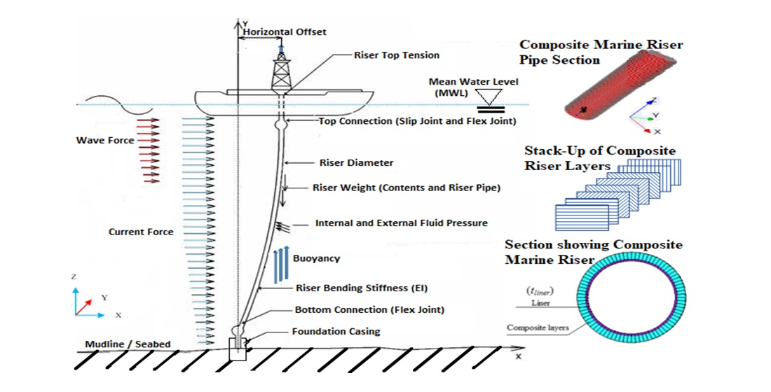
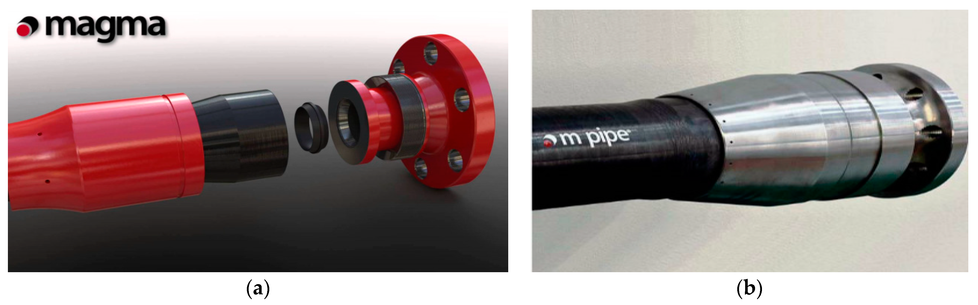
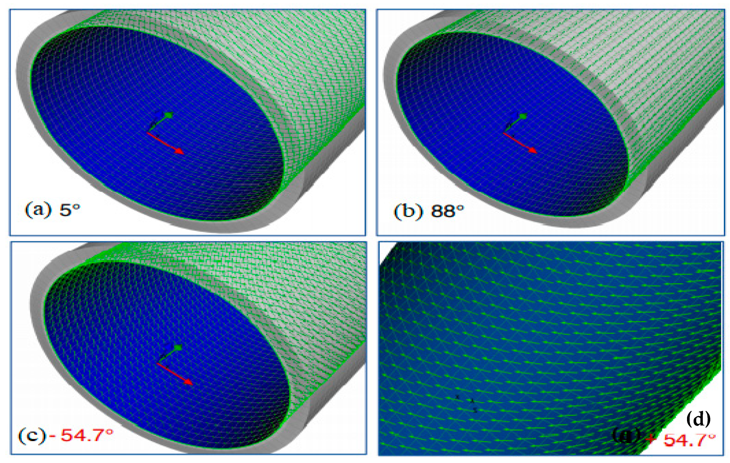
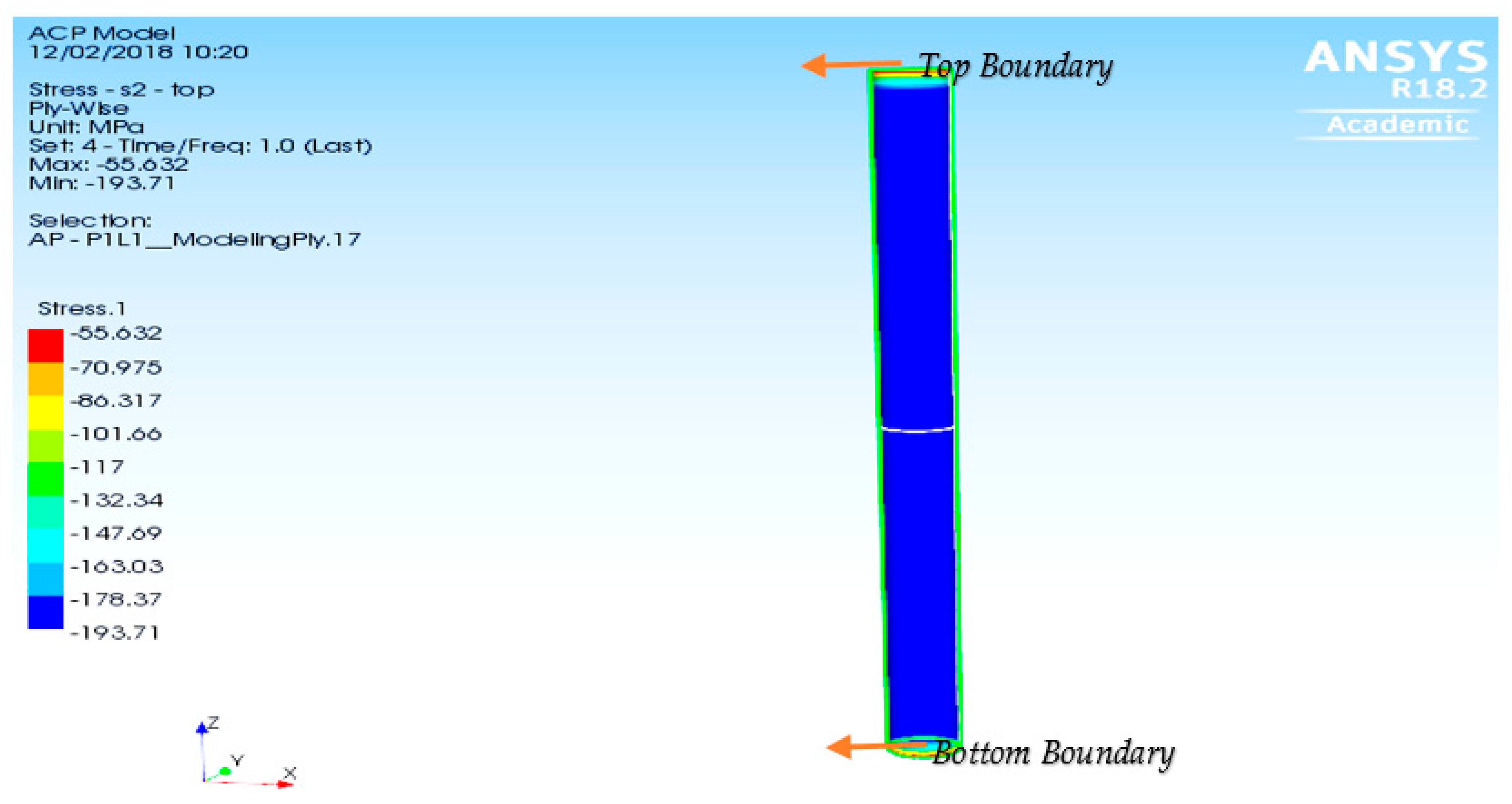
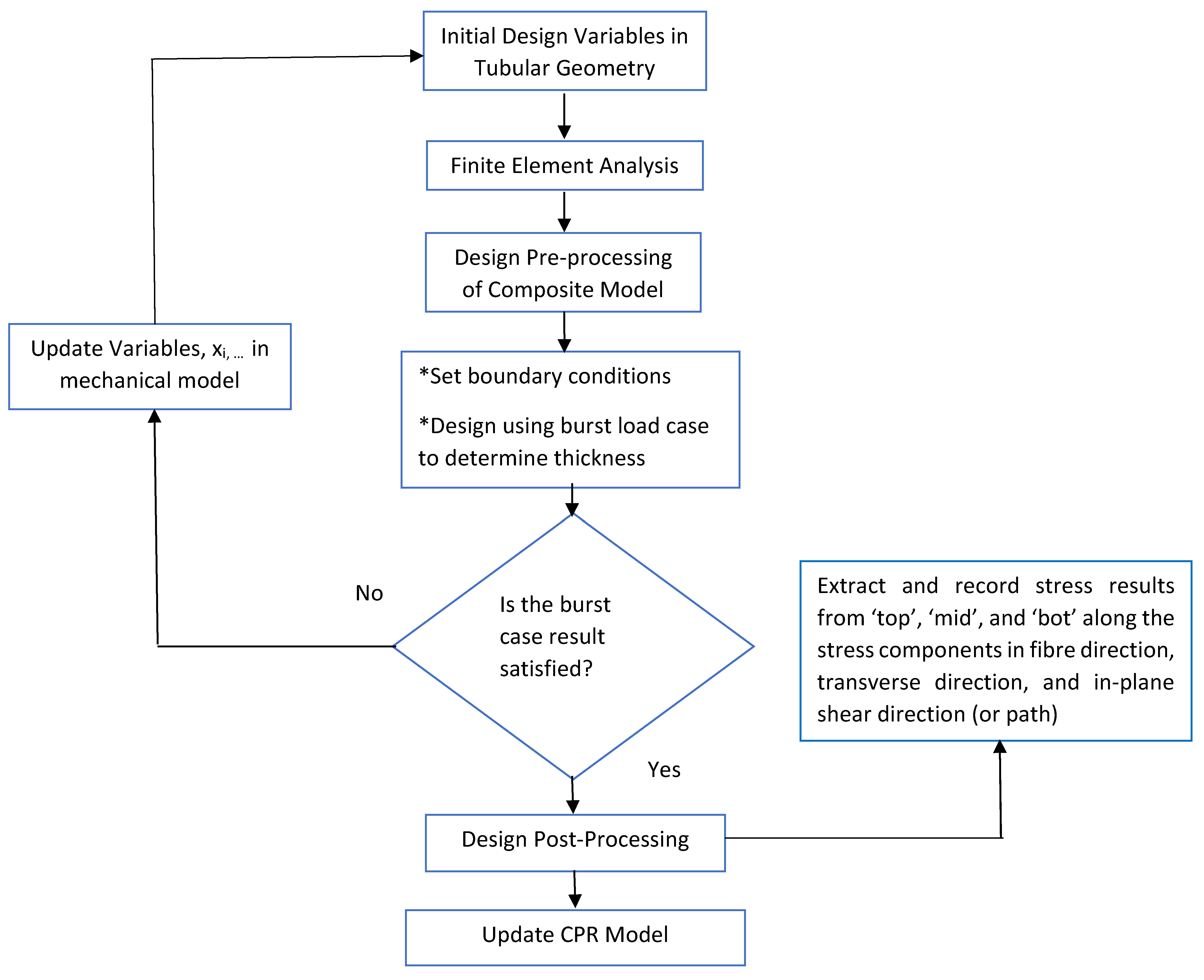
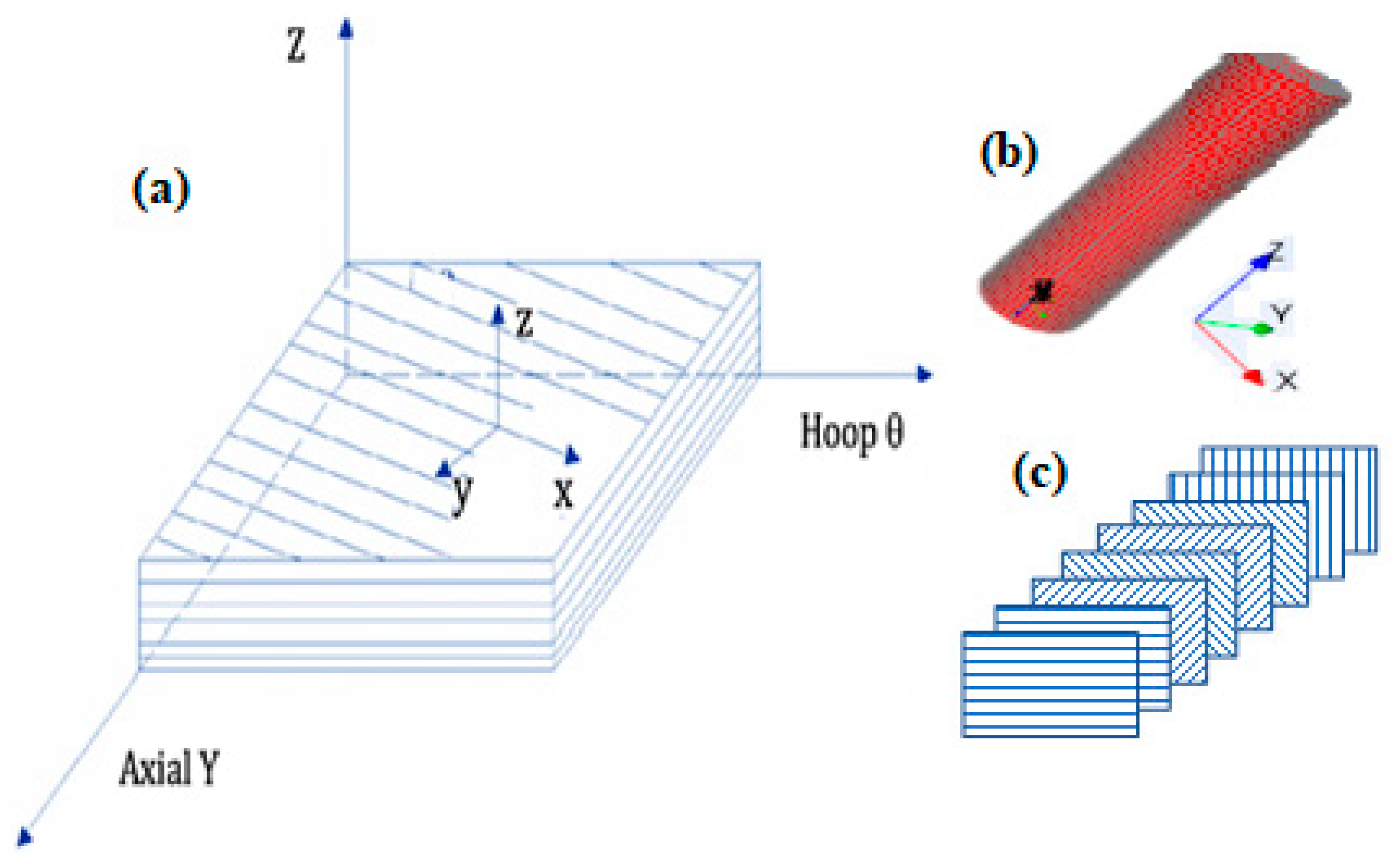
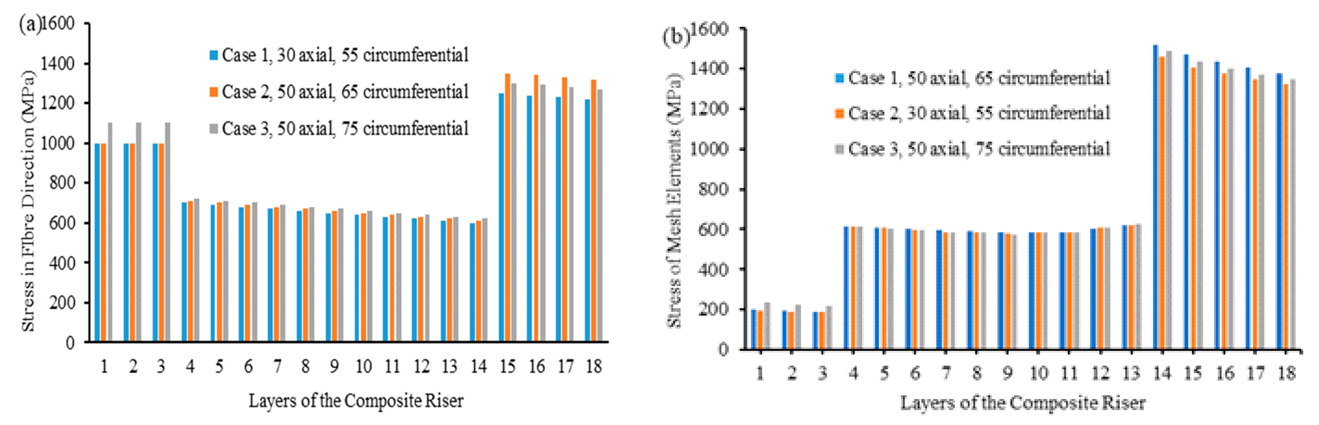
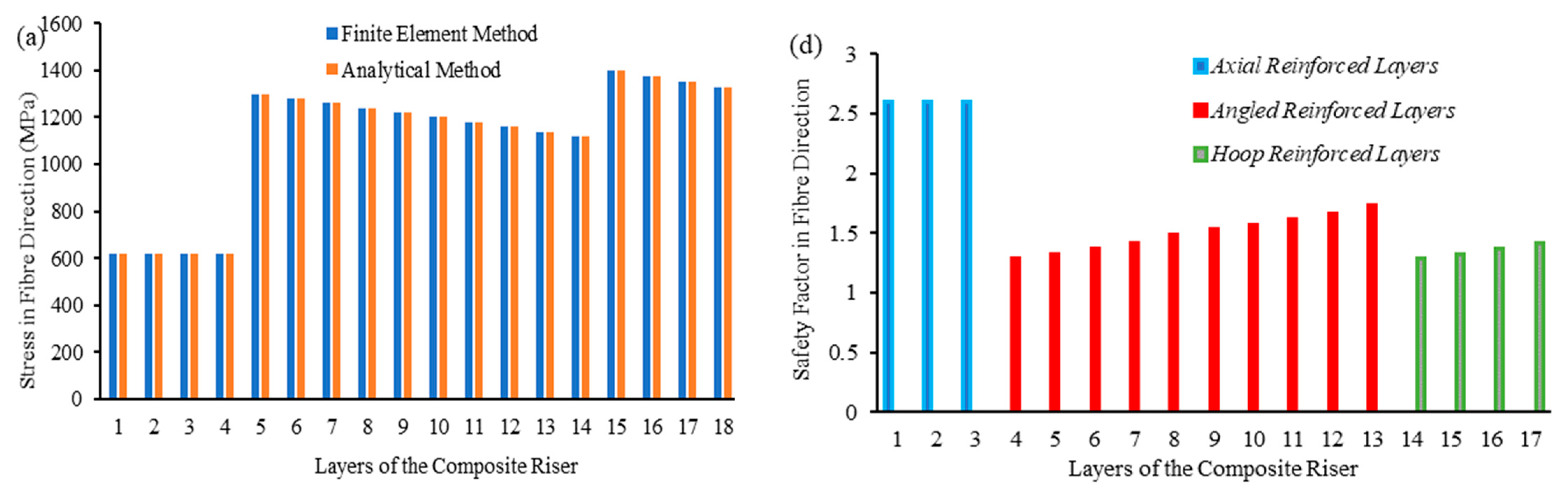
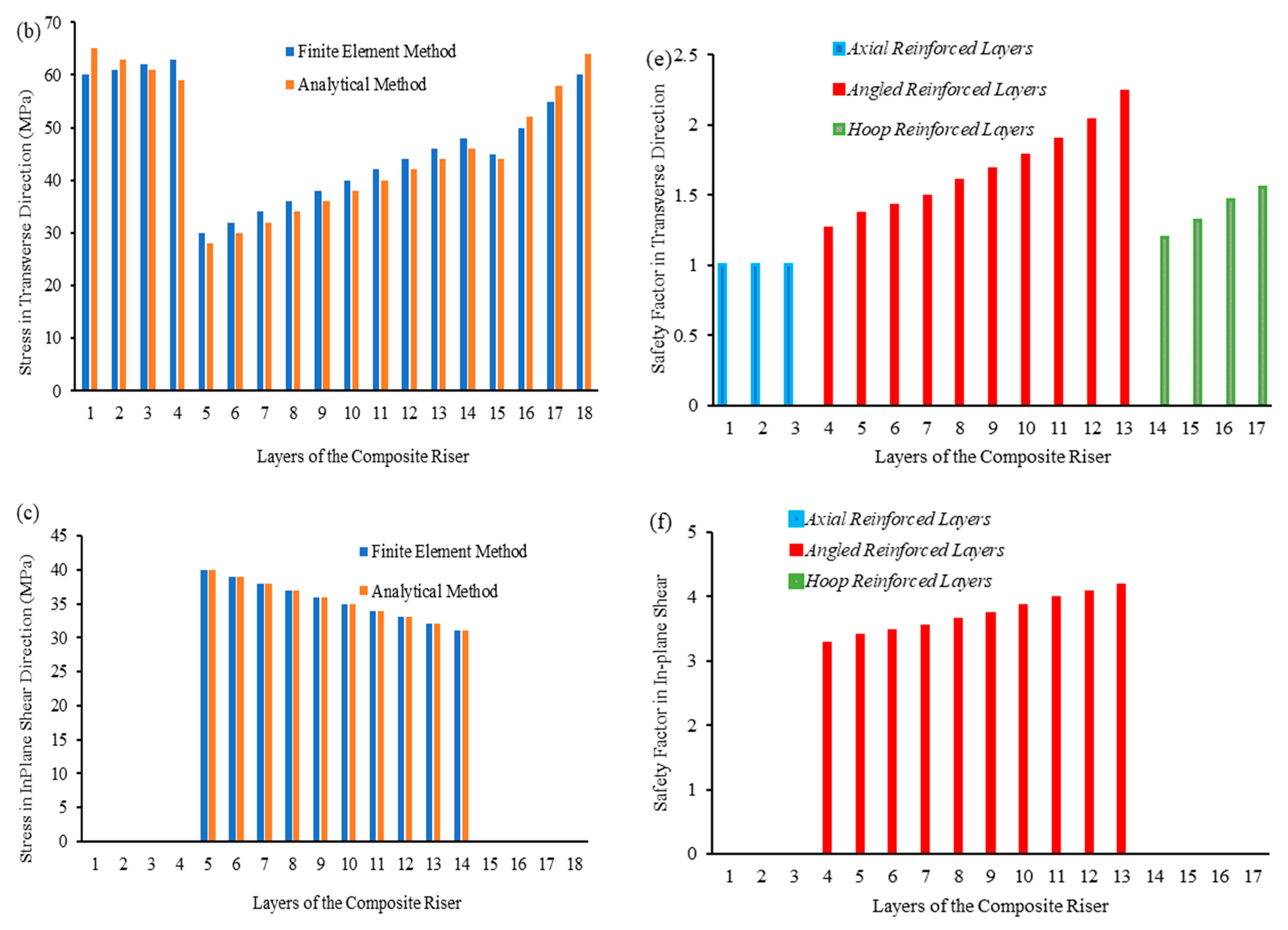
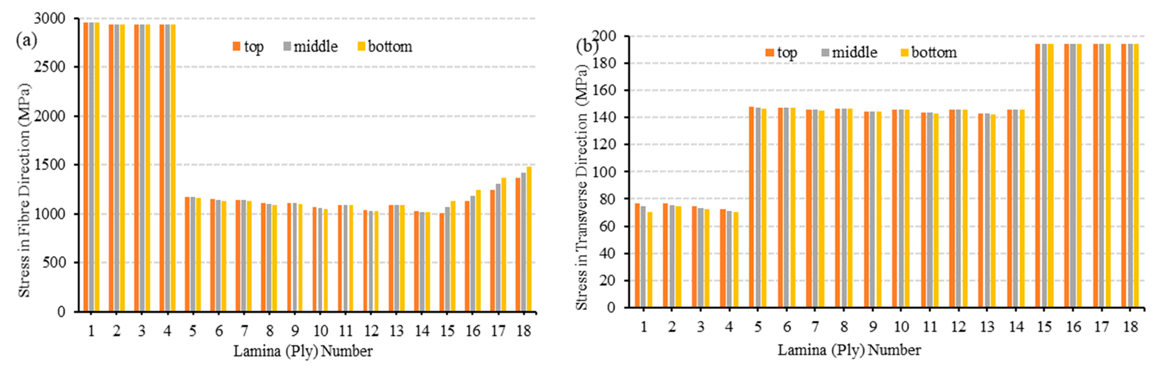
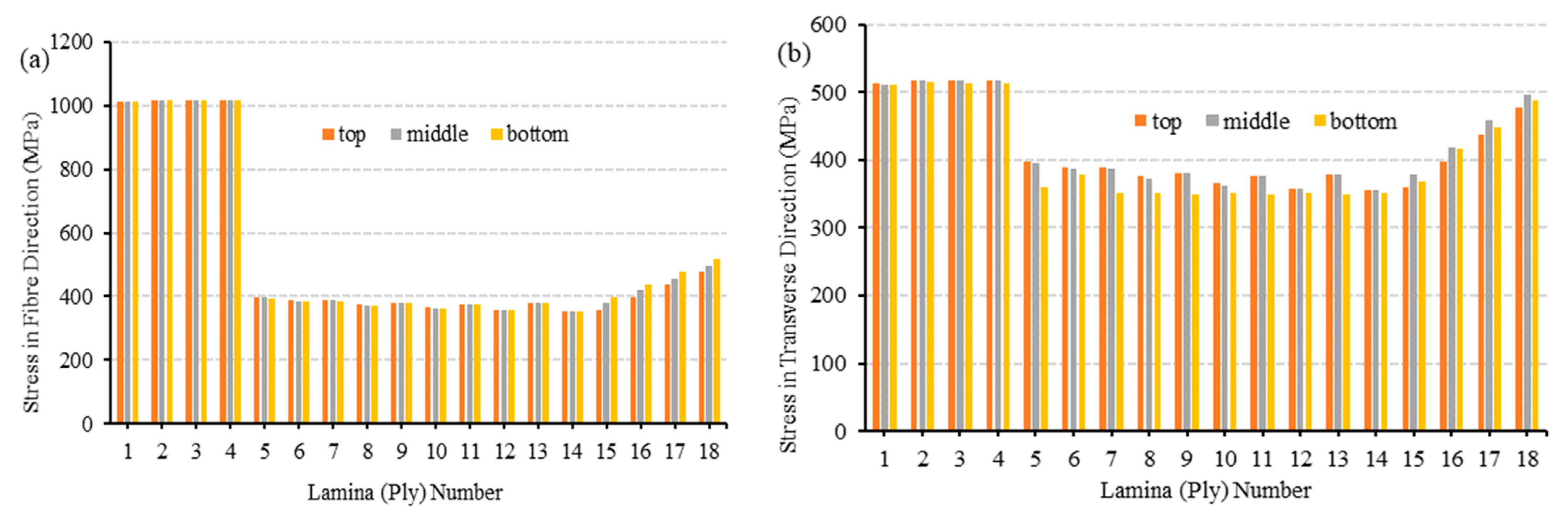
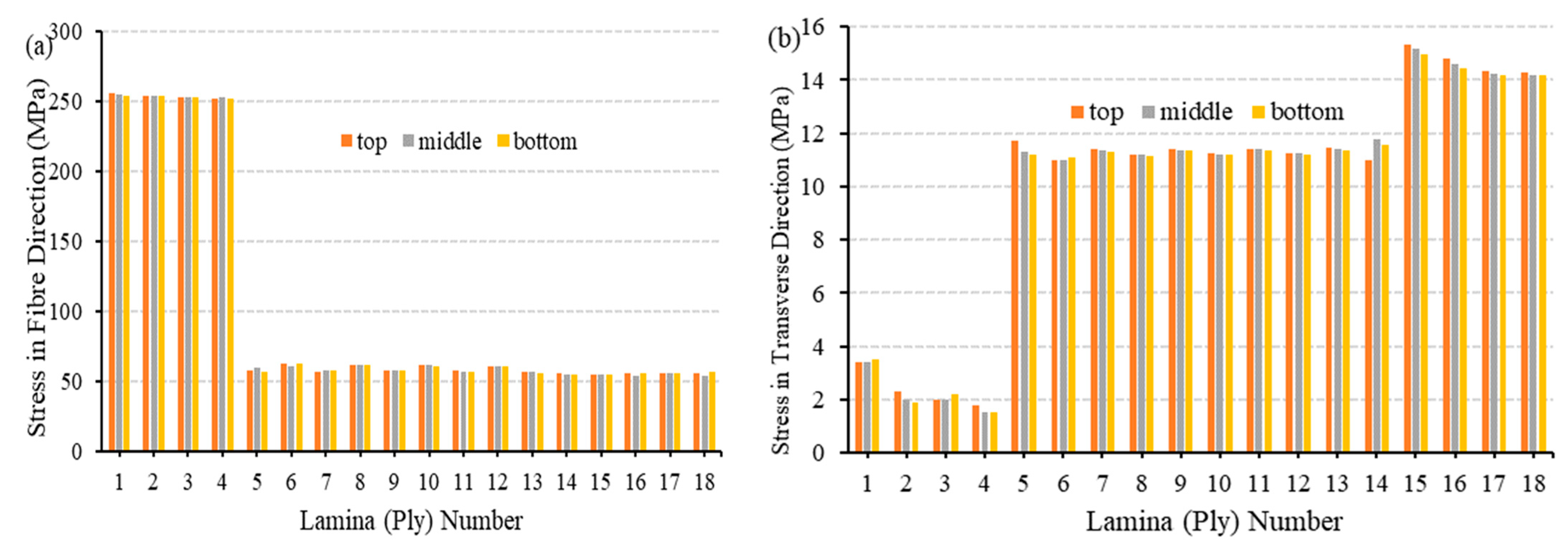
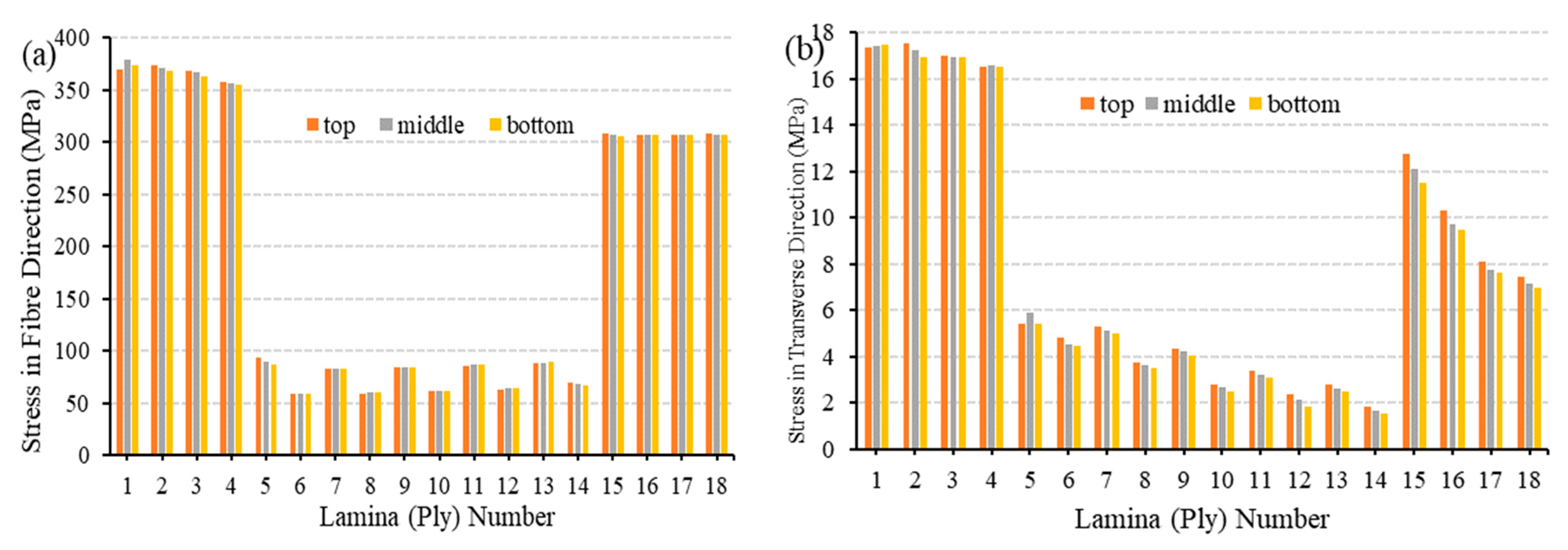
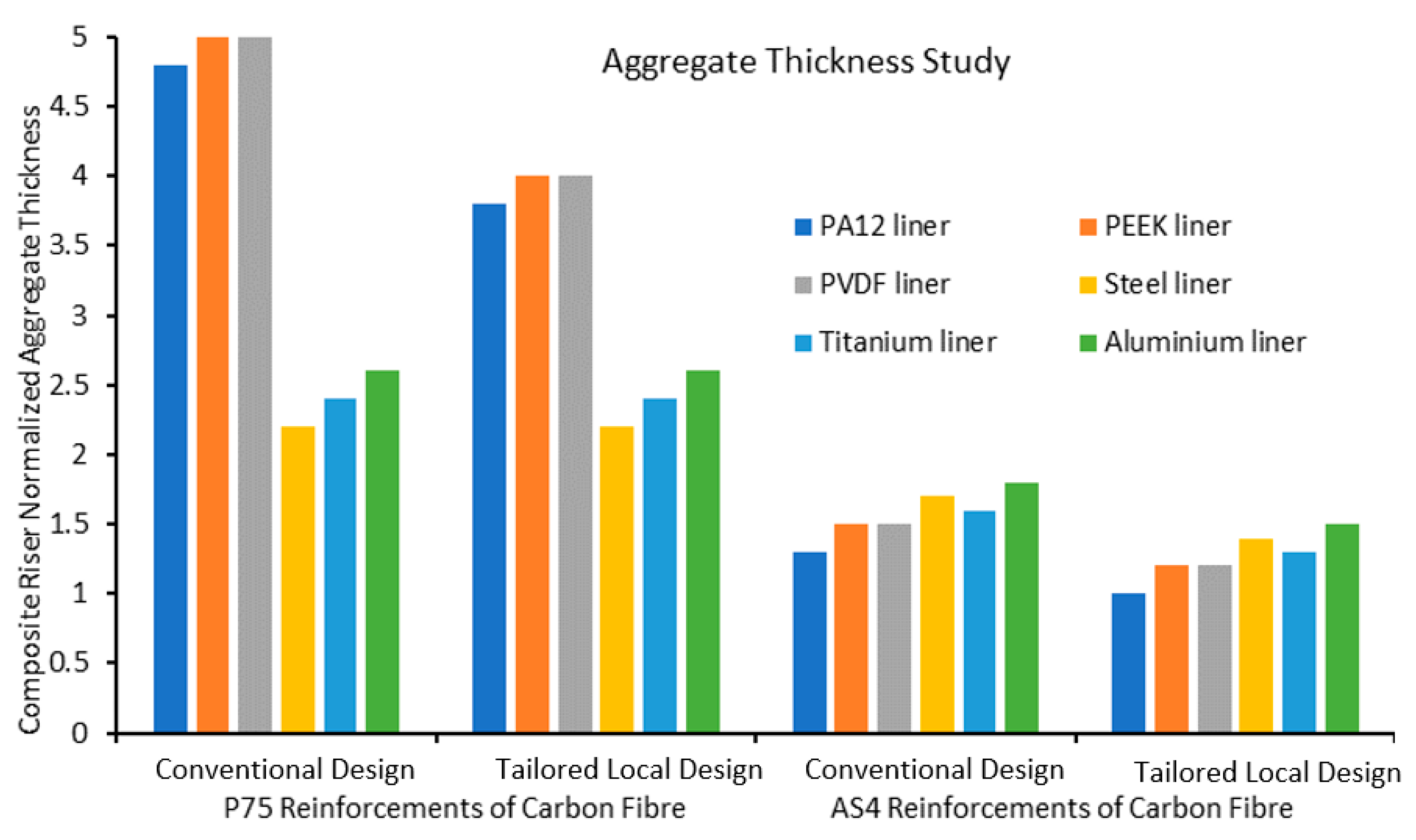
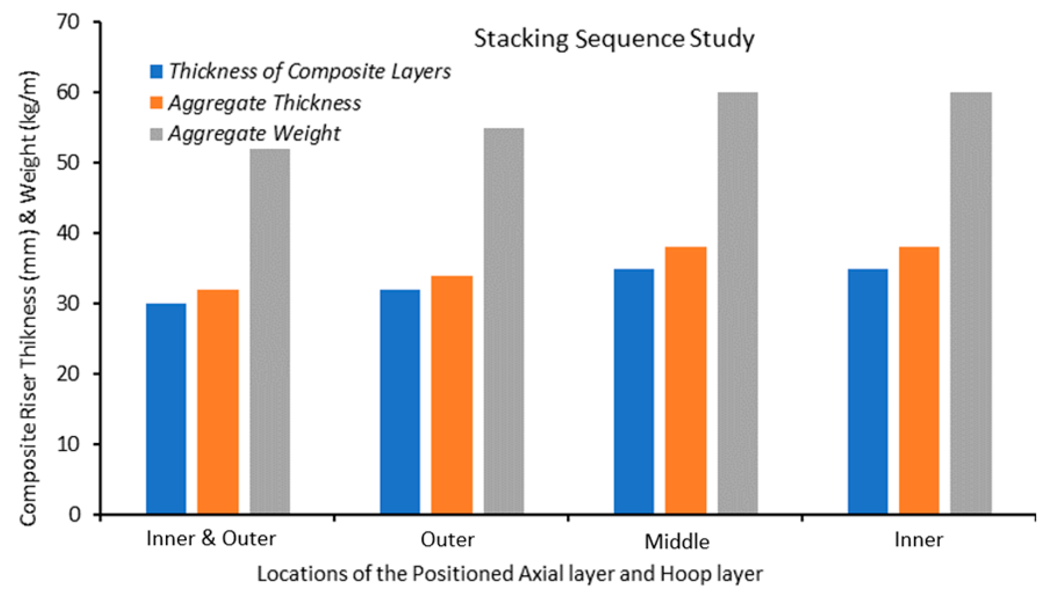
Table 1.
Parameters for the composite riser model.
| Particulars | Value | Unit |
|---|---|---|
| Material | Composites | - |
| Number of Layers | 17, 18, and 21 | - |
| Failure Criteria | Max. Stress | - |
| Innermost Layer | Liner | - |
| Outer Diameter | 0.305 | m |
| Length of Riser Section | 3.000 | m |
| Ocean Depth | 2030.000 | m |
| Surface Area | 7.661 | m2 |
Table 2.
Material characteristics for unidirectional FRP lamina.
| Parameter/Description | Fibre Volume Fraction | Density (kg/m3) | E1 (GPa) | E2 = E3 (GPa) | G12 = G13 (GPa) | G23 (GPa) | (GPa) | (GPa) | (GPa) | (GPa) | τ12 (GPa) | ʋ12 = ʋ13 | ʋ23 |
|---|---|---|---|---|---|---|---|---|---|---|---|---|---|
| (APC2) IM7/PEEK | 0.55 | 1320.0 | 172.00 | 8.30 | 5.50 | 2.80 | 2900 | 1300 | 48.3 | 152.0 | 68.0 | 0.27 | 0.48 |
| (V2021) Carbon fibre/Epoxy | 0.55 | 1580.0 | 10.32 | 10.32 | 7.97 | 3.70 | 4900 | 1470 | 69.0 | 146.0 | 98.0 | 0.27 | 0.50 |
| (APC2) P75/PEEK | 0.55 | 1773.0 | 280.00 | 6.70 | 3.43 | 1.87 | 668 | 364 | 24.8 | 136.0 | 68.0 | 0.30 | 0.69 |
| (T700) Carbon fibre/Epoxy | 0.58 | 1580.0 | 230.00 | 20.90 | 27.60 | 2.70 | 4900 | 1470 | 69.0 | 146.0 | 98.0 | 0.20 | 0.27 |
| (APC2) AS4/PEEK | 0.58 | 1561.0 | 131.00 | 8.70 | 5.00 | 2.78 | 1648 | 864 | 62.4 | 156.8 | 125.6 | 0.28 | 0.48 |
| (S-2) Glass fibre/Epoxy | 0.55 | 2464.0 | 87.93 | 16.00 | 9.00 | 2.81 | 4890 | 1586 | 55.0 | 148.0 | 70.0 | 0.26 | 0.28 |
| (938) P75/Epoxy | 0.55 | 1776.0 | 310.00 | 6.60 | 4.10 | 2.12 | 720 | 328 | 22.4 | 55.2 | 176.0 | 0.29 | 0.70 |
| (938) AS4/Epoxy | 0.60 | 1530.0 | 135.40 | 9.37 | 4.96 | 3.20 | 1732 | 1256 | 49.4 | 167.2 | 71.2 | 0.32 | 0.46 |
FRP—fibre-reinforced plastics; S-2—AGY glass fibre; T700—Toray carbon fibre; PEEK—polyether-ether-ketone. 1st subscript—fibre path; 2nd subscript—transverse path; 3rd subscript—in-plane shear path. Composite ply calculations were on stress components with orientations in these 3 directions called stress directions or stress paths. ʋ1, ʋ2, ʋ3—Poisson’s ratios; G12, G13, G23—shear moduli; E2, E2, E3—elastic moduli. HS—high-strength; superscript C—compression; superscript T—tension.
Table 3.
Material characteristics for liners.
| Parameter/Description | Poisson’s Ratio, ʋ | Elongation at Break (%) | Ultimate Stress (MPa) | Yield Stress (MPa) | Elastic Modulus (MPa) | Density (kg/m3) |
|---|---|---|---|---|---|---|
| (Victrex) PEEK | 0.400 | 45.00 | 125.0 | 110.0 | 4.0 | 1300.0 |
| HDPE | 0.460 | 10.00 | 43.0 | 1350.0 | 565.0 | 995.0 |
| (Nylon PA) PA12 | 0.400 | 10.00 | 54.0 | 1500.0 | 540.0 | 1010.0 |
| PVDF | 0.400 | 10.00 | 54.0 | 1540.0 | 550.0 | 1780.0 |
| (X80) Steel | 0.300 | 5.90 | 950.0 | 880.0 | 207.0 | 7850.0 |
| (1953T1) Aluminium alloy | 0.300 | 7.50 | 540.0 | 480.0 | 71.0 | 2780.0 |
| (Ti6Al4V) Titanium alloy | 0.342 | 14.00 | 950.0 | 880.0 | 113.8 | 4430.0 |
PEEK—polyether-ether-ketone; HDPE—high-density polyethelene; PVDF—polyvinylidene fluoride; PA12—polyamide 12.
Table 4.
Selected design, stack-up sequences, material configurations, and CPR’s composite lamina orientations.
Table 4.
Selected design, stack-up sequences, material configurations, and CPR’s composite lamina orientations.
| Liner Material | Liner Thickness (mm) | Fibre | Matrix | Lay-Up | Lamina Thickness (mm) | ||
|---|---|---|---|---|---|---|---|
| 0° | ±53.5° | 90° | |||||
| Titanium | 9 | AS4 | PEEK | [903,(±53.5)5,05] | 1.84 | 1.48 | 0.6 |
| Titanium | 9 | IM7 | PEEK | [903,(±53.5)5,05] | 1.84 | 1.48 | 0.6 |
| Titanium | 9 | P75 | PEEK | [903,(±53.5)5,05] | 1.84 | 1.48 | 0.6 |
| Titanium | 9 | AS4 | Epoxy | [903,(±53.5)5,05] | 1.84 | 1.48 | 0.6 |
| Titanium | 9 | IM7 | Epoxy | [903,(±53.5)5,05] | 1.84 | 1.48 | 0.6 |
| Titanium | 9 | P75 | Epoxy | [903,(±53.5)5,05] | 1.84 | 1.48 | 0.6 |
Table 5.
The design loadings for modelling the composite riser.
| Design Loads | Parameters | Detailed Information of Load |
|---|---|---|
| Design Load 01 | Tension Load | Using 2.25 as factor of load and the max. tensions |
| Design Load 02 | Internal Pressure (Burst) + effect of load at ends | Using the int. pres. at 155.25 MPa is utilised |
| Design Load 03 | External Pressure (Collapse) | Using the ext. pres. at 60.00 MPa is utilised |
| Design Load 04 | Combined—Tension cum Internal Pressure | Using the int. pres. at 155.25 MPa for the tensions |
| Design Load 05 | Combined—Tension cum External Pressure | Using 2.25 as factor of load for 19.50 MPa ext. pres. |
Table 6.
Geometry and orientation of the [90/(0/90)4] composite plies for conventional design.
| Ply/Layer | Name of Layer | Inclination Angle/Orientation (°) | Thickness (mm) |
|---|---|---|---|
| 00 | The Liner | 2.00 | |
| 1, 3, 5, 7, 9, 11, 13, 15, 17, 19, 21 | Hoop Layers | 90 | 1.62 |
| 2, 4, 6, 8, 10, 12, 14, 16, 18, 20 | Axial Layers | 0 | 1.58 |
Table 7.
Lay-up/ply inclination angle for local design for the [04,(±53.5)5,904] and [903,(±53.5)5,05] configurations.
Table 7.
Lay-up/ply inclination angle for local design for the [04,(±53.5)5,904] and [903,(±53.5)5,05] configurations.
| Design | Configuration | [04,(±53.5)5,904] | [903,(±53.5)5,05] | ||
|---|---|---|---|---|---|
| Ply/Layer | Name of Layer | Inclination Angle/Orientation (°) | Thickness (mm) | Inclination Angle/Orientation (°) | Thickness (mm) |
| 00 | The Liner | 0.0 | 2.00 | 0.0 | 9.00 |
| 01 | Axial Layers | 0.0 | 1.58 | 0.0 | 1.84 |
| 02 | 0.0 | 1.58 | 0.0 | 1.84 | |
| 03 | 0.0 | 1.58 | 0.0 | 1.84 | |
| 04 | 0.0 | 1.58 | 0.0 | 1.84 | |
| 05 | Angled Layers (or Off-axis Layers) | 53.5 | 1.88 | 53.5 | 1.48 |
| 06 | −53.5 | 1.88 | −53.5 | 1.48 | |
| 07 | 53.5 | 1.88 | 53.5 | 1.48 | |
| 08 | −53.5 | 1.88 | −53.5 | 1.48 | |
| 09 | 53.5 | 1.88 | 53.5 | 1.48 | |
| 10 | −53.5 | 1.88 | −53.5 | 1.48 | |
| 11 | 53.5 | 1.88 | 53.5 | 1.48 | |
| 12 | −53.5 | 1.88 | −53.5 | 1.48 | |
| 13 | 53.5 | 1.88 | 53.5 | 1.48 | |
| 14 | −53.5 | 1.88 | −53.5 | 1.48 | |
| 15 | Hoop Layers | 90.0 | 1.62 | 90.0 | 1.60 |
| 16 | 90.0 | 1.62 | 90.0 | 1.60 | |
| 17 | 90.0 | 1.62 | 90.0 | 1.60 | |
| 18 | 90.0 | 1.62 | 90.0 | 1.60 | |
Table 8.
Riser deformation and liner stress during burst event’s preliminary design.
| Particulars | Value | Unit |
|---|---|---|
| Maximum Riser Deformation | 3.37 | mm |
| Ultimate Stress of Titanium Alloy | 950.00 | MPa |
| Yield Stress of Titanium Alloy | 880.00 | MPa |
| Titanium Liner’s Equivalent Stress | 550.00 | MPa |
Table 9.
Riser deformation and liner stress during collapse event’s preliminary design.
| Particulars | Value | Unit |
|---|---|---|
| Riser’s Maximum Deformation | 1.34 | mm |
| Ultimate Stress of Titanium Alloy | 950.00 | MPa |
| Yield Stress of Titanium Alloy | 880.00 | MPa |
| Titanium Liner’s Equivalent Stress | 525.00 | MPa |
Table 10.
Riser deformation and liner stress during tension event’s preliminary design.
| Particulars | Value | Unit |
|---|---|---|
| Riser’s Maximum Deformation | 7.78 | mm |
| Ultimate Stress of Titanium Alloy | 950.00 | MPa |
| Yield Stress of Titanium Alloy | 880.00 | MPa |
| Titanium Liner’s Equivalent Stress | 162.00 | MPa |
Table 11.
Riser deformation and liner stress during tension cum external pressure event’s preliminary design.
Table 11.
Riser deformation and liner stress during tension cum external pressure event’s preliminary design.
| Particulars | Value | Unit |
|---|---|---|
| Riser’s Maximum Deformation | 11.80 | mm |
| Ultimate Stress of Titanium Alloy | 950.00 | MPa |
| Yield Stress of Titanium Alloy | 880.00 | MPa |
| Titanium Liner’s Equivalent Stress | 253.00 | MPa |
Table 12.
Considerations for effect of weight per unit area for 12 design cases.
| Design Case | Liner Material | Fibre | Matrix | Lay-Up | Lamina Thickness (mm) | ||
|---|---|---|---|---|---|---|---|
| 0° | ±53.5° | 90° | |||||
| Case 1 | Titanium | AS4 | PEEK | [05,(±53.5)5,905] | 2.49 | 1.7 | 0.6 |
| Case 2 | Titanium | AS4 | PEEK | [903,(±53.5)5,05] | 2.49 | 1.7 | 1.84 |
| Case 3 | Titanium | AS4 | PEEK | [903,(±53.5)5,05] | 2.49 | 1.7 | 3.25 |
| Case 4 | Titanium | AS4 | PEEK | [05,(±53.5)5,905] | 2.49 | 1.7 | 1.7 |
| Case 5 | Titanium | AS4 | PEEK | [905,(±53.5)5,05] | 2.49 | 1.7 | 1.84 |
| Case 6 | Titanium | AS4 | PEEK | [(±53.5)5,05,905] | 1.15 | 1.7 | 1.84 |
| Case 7 | Titanium | AS4 | PEEK | [06,(±53.5)5,904] | 2.49 | 1.7 | 0.6 |
| Case 8 | Titanium | AS4 | PEEK | [905,(±53.5)5,05] | 2.49 | 1.7 | 0.6 |
| Case 9 | Titanium | AS4 | PEEK | [905,(±53.5)5,05] | 1.15 | 1.7 | 1.84 |
| Case 10 | Titanium | AS4 | PEEK | [(±53.5)5,905,05] | 1.15 | 1.7 | 1.84 |
| Case 11 | Titanium | AS4 | PEEK | [(±53.5)5,905,05] | 1.15 | 1.7 | 3.25 |
| Case 12 | Titanium | AS4 | PEEK | [06,(±53.5)5,904] | 2.49 | 1.7 | 1.7 |
Table 13.
Comparison of deep water TTR steel riser under 2000 m water depth against its structural weight.
Table 13.
Comparison of deep water TTR steel riser under 2000 m water depth against its structural weight.
| Depth (m) | Thickness (mm) | Weight (kg/m) |
|---|---|---|
| 0–1000 | 155 | 23 |
| 1000–1600 | 162 | 24 |
| 1600–2000 | 170 | 25 |
| ~2000 (approx. range) | 160 |
Table 14.
Comparison of weights between a typical TTR steel riser and composite riser.
| Design | Configuration | OD, Outer Diameter | OD Increase | Riser Weight | Weight Saving |
|---|---|---|---|---|---|
| Steel TTR | [90/(0/90)4] | 273–275 | - | 160 | - |
| Preliminary | [54,(±54.7)10,884] | 314.6 | 13% | 73 | 54% |
| Second | [04,(±53.5)5,904] | 315.2 | 13.5% | 70 | 57% |
| Final | [33,(±62)10,885] | 316.6 | 14% | 54 | 66% |
Publisher’s Note: MDPI stays neutral with regard to jurisdictional claims in published maps and institutional affiliations. |
© 2022 by the authors. Licensee MDPI, Basel, Switzerland. This article is an open access article distributed under the terms and conditions of the Creative Commons Attribution (CC BY) license (https://creativecommons.org/licenses/by/4.0/).
Share and Cite
MDPI and ACS Style
Amaechi, C.V.; Gillet, N.; Ja’e, I.A.; Wang, C. Tailoring the Local Design of Deep Water Composite Risers to Minimise Structural Weight. J. Compos. Sci. 2022, 6, 103. https://0-doi-org.brum.beds.ac.uk/10.3390/jcs6040103
AMA Style
Amaechi CV, Gillet N, Ja’e IA, Wang C. Tailoring the Local Design of Deep Water Composite Risers to Minimise Structural Weight. Journal of Composites Science. 2022; 6(4):103. https://0-doi-org.brum.beds.ac.uk/10.3390/jcs6040103
Chicago/Turabian StyleAmaechi, Chiemela Victor, Nathaniel Gillet, Idris Ahmed Ja’e, and Chunguang Wang. 2022. "Tailoring the Local Design of Deep Water Composite Risers to Minimise Structural Weight" Journal of Composites Science 6, no. 4: 103. https://0-doi-org.brum.beds.ac.uk/10.3390/jcs6040103