Article

Stiffness Retention in Cyclic-Loaded CFRP Composites Produced via Novel Automatic Tape Laying

1
Faculty of Science, Engineering and Technology, Swinburne University of Technology, Hawthorn, VIC 3122, Australia
2
CSIRO, Clayton, VIC 3168, Australia
*
Author to whom correspondence should be addressed.
Submission received: 15 January 2024 / Revised: 21 February 2024 / Accepted: 1 March 2024 / Published: 3 March 2024
(This article belongs to the Special Issue Carbon Fiber Composites, Volume III)

Abstract

:
Sixteen-head automatic tape laying of non-crimped carbon-fibre-reinforced plastic is performed, and the fibre alignment is compared with that produced via hand laying. The effect of fibre alignment is tested via quasi-static and cyclic three-point bending tests. Using the Fill Multilayer (a 16-head tape-laying machine), precision fibre laying of unidirectional fabrics is performed with deliberate misalignment to examine the effect of fibre orientation and investigate the random effect on longitudinal misalignment. The automatic tape-layered coupons are compared with hand-layered carbon fibre tapes to investigate the relationship between the fibre alignment and the flexural strength. A 52% reduction in the fibre alignment scatter is achieved via the Fill Multilayer. Fibre orientation increases lead to a higher flexural strength of 16.08% for Fill Multilayer-made coupons compared with hand-layered samples. An investigation of the correlation between fibre alignment and flexural strength shows that shear-based failure increases exponentially as the alignment decreases. Fill Multilayer-made coupons have a higher void concentration due to ultrasonic welding, but also the highest modulus and flexural strength, as fibre misalignment is reduced to 1.68°, with a modulus degradation of 1.4%.

1. Introduction

Composites such as carbon-fibre-reinforced plastic (CFRP) have the potential to reduce automotive components by 60–80% [1,2,3,4]. CFRP is also frequently adopted in other fields and applications, such as for the structural reinforcement of buildings [5,6]. However, CFRP is produced slowly by hand laying, which lowers reproducibility [7,8,9,10]. The introduction of automated tape laying (ATL) has accelerated composite part manufacturing in the automotive industry, helping composites to become a more attractive alternative to reduce the weight of structural components. ATL has the advantages of increased efficiency, reproducibility and laying accuracy over traditional hand stacking or raw material strips [11,12,13]. Recent developments in multiheaded construction have enabled the parallel laying of multiple tapes, allowing for even faster composite part manufacturing to keep up with automotive demand. A key issue with CFRP is reproducibility; due to the multifibre nature of CFRP, the alignment of individual tows within the laminate can cause major deviations in mechanical performance.
The ATL system used here is the Fill Multilayer machine [14]. In this machine, a combination of thermoset and thermoplastic prepregs can be used in the machine heads and dry fabrics. Using typical prepregs in the Fill Multilayer causes issues with adhesion in the rollers; this is mitigated with zero-tack prepregs. In comparison with previous ATL machines (e.g., those described in [15,16]), ultrasonic welding of the prepregs or dry fabrics is used to prevent tow shifting. Ultrasonic welding is employed to adhere plies together in a novel approach using the Fill Multilayer to adhere zero-tack resin prepregs. The effect of ultrasonic welding is optimised regarding stack welding penetration and adhesion between plies without causing significant defects in the final laminate during consolidation [17,18].
Automatic tape-laying systems require both a low tack and dynamic stiffness in order for prepreg fibres to be spooled and unspooled without resin adhering to the roll [19]. The random scattering of the fibres produced using the Fill Multilayer is compared with that of handmade CFRP coupons to investigate fibre alignment in different laying methods. The preform is held together with ultrasonic weld dots to prevent the preform from shifting during curing. Fibre alignment is a critical issue, with the numerous defects introduced during composite manufacturing leading to random fibre alignment, as outlined in the reviews by Oromiehie et al. [12] and Falk et al. [11]. Oromiehie et al. indicated that many defects in pre-impregnated fibres during resin (prepreg) manufacturing occur before tape placement due to fibre spooling and unspooling, which causes misalignment due to resin adhesion. Tape defects such as splitting can cause gaps. Croft et al. [20] showed that gaps in the tape are caused by either fibre shifting or tape defects, leading to a decrease in the compression strength by 3 to 12%. Minimising the alignment defects introduced after placement is critical for maximising part performance. As Jeppesen et al. [21] showed, the manufacturing approach is the main contributor to fibre misalignment and the waviness of the produced composite.
Analyses of the fibre angle have shown that a high degree of misalignment is correlated with data scattering in fatigue testing [13,22,23]. To further research the randomness in fabrics, this investigation will use different fibre angles in ATL. Previous alignment studies show a linear correlation between the fibre alignment and the flexural strength [15,24]. Manufacturing defects, leading to fibre misalignment, are highlighted by Alam et al. [25] as being the primary cause of data scattering in CFRP. Random fibre alignment is a crucial aspect affecting a composite’s permeability during the filling stage of liquid composite moulding processes [26,27,28,29].
In this paper, the fibre alignment of composites layered using either Fill Multilayer or hand laying is investigated to determine the relationship between fibre alignment and flexural strength. Alignments of less than 5° are used to determine whether the alignment contributes to the mechanical performance of the composite laminate. The Fill Multilayer uses a zero-tack UD prepreg; this is compared with the same prepreg produced via hand layering and a UD CFRP. The UD CFRP contains cross stitching to prevent ply splitting; however, the stitching adds waviness. This waviness, which leads to longitudinal misalignment, is investigated and is compared with random misalignment due to stitching during hand laying. To test the precision of the Fill Multilayer, the UD CFRP fabric is deliberately misaligned by 5° and 90° to investigate the alignment effect on the flexural behaviour. An angle of 5° is chosen as it is difficult to accurately hand lay tape with a 5° offset, and 90° is chosen because it can be cut from the UD plates. In the Fill Multilayer, a prepreg of unidirectional (UD) CFRP is used, interlayered by hand, to determine the static and cyclic loading characteristics via three-point bending tests. The flexural characteristics of the composites produced using the Fill Multilayer are determined and compared against those of composites fabricated via hand laying. The alignment of the manufactured carbon-fibre-reinforced plastic coupons is compared with those manufactured via hand laying.

2. Methodology

2.1. Material Characteristics and Resin Curing

The CFRPs used were the intermediate modulus epoxy prepregs shown in Table 1. The first material contained a cross stitch, which induced waviness in the fabric. The other material was an intermediate modulus epoxy zero-tack prepreg. The zero-tack additive prevented the prepreg from adhering during unravelling. Curing was conducted in a press at 18 MPa compression; the mould was coated in mould release wax to enable part removal. Curing was carried out as per the manufacturer’s recommendations (FILL). The Fill Multilayer-produced non-crimped fabric was isothermally cured at 150 °C for 5 min, and the crimped fabric without zero-tack resin was cured at 130 °C for 5 min. An increase in temperature was required to ensure curing due to the tackifiers in the zero-tack resin additive. The hot plates were then released from the mould and cooled at room temperature overnight. The fibres were displaced during pressing, causing mould edge misalignment. However, the edge misalignment error was minimal as the edges were discarded. The 200 mm2 coupons were layered with a 50 mm overhang and manually cut to fill the mould.
Cutting the material led to an additional potential error in the hand-placed laminates. Instead of using a machined length and tapes to control the width, as was the case in the Fill Multilayer, during hand laying, the material was cut to size, creating a uniform edge distribution. For this reason, coupons were cut away from the edge to prevent waviness, which caused scatter in the alignment data. Each plate was manufactured with 10 plies of CFRP and compressed to a 2 mm thickness; for off-the-shelf CFRP, 6 plies were used and pressed to a thickness of 2 mm. Maintaining a constant coupon geometry ensured a reproducible result during testing, as both fabrics consisted of carbon fibres with comparable intermediate tensile moduli.

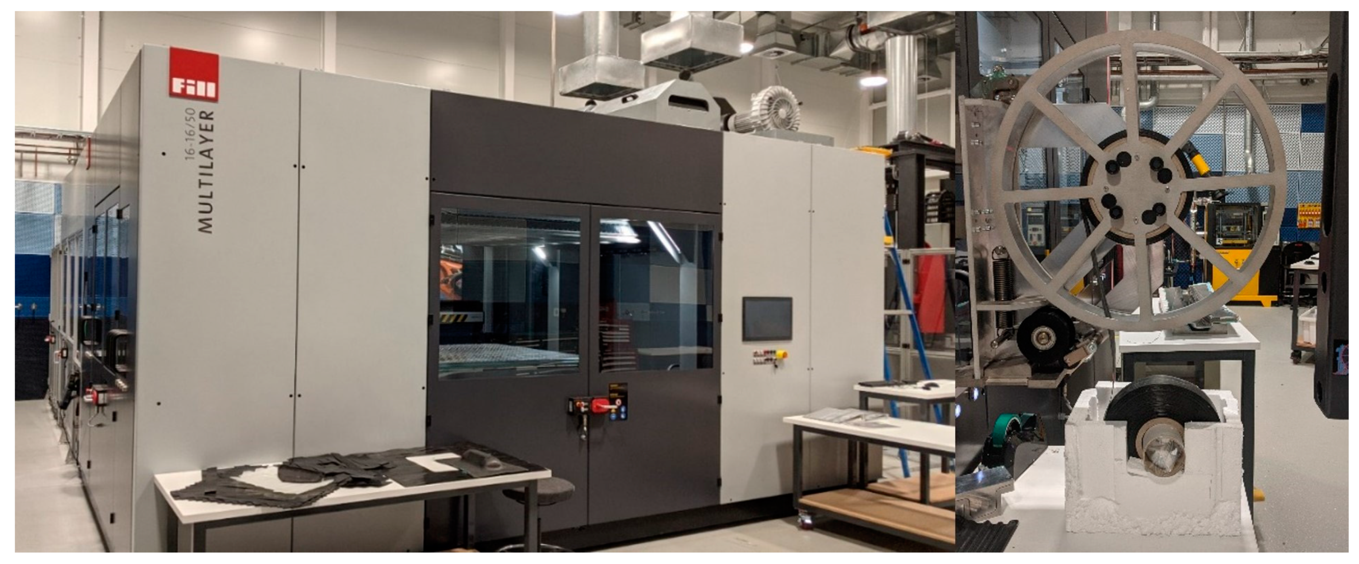
2.2. Fill Multilayer Tape Laying

This article investigates the Fill Multilayer (shown in Figure 1) and the performance of its products in both static and dynamic scenarios. Automatic tape laying was performed and the resulting fibre orientation and mechanical bending were studied and further compared with those resulting from hand laying. A cross-section micrograph of the surface was used to determine fibre orientation changes between stackings. The development of high-stiffness light materials required a higher tolerance between samples. This tolerance was the deviation between samples from different composite laminates. The comparison between defects and mechanical stiffness under static and dynamic bending would be the basis of the measurements.
There were several issues when stacking UD fabrics in the Fill Multilayer that needed to be addressed. Firstly, the fabrication of a 200 mm2 CFRP plate required the tapes to be stacked on top of one another. However, ultrasonic welding was performed in the centre of the tape, as shown in Figure 2. This central placement of ultrasonic weld marks for UD fabrics led to no adhesion to the adjacent fibre stack; thus, overlapped fibre layers were required to achieve a fully adhered stack that could be transported without separating. In contrast, in offset fabrics, the change in fibre direction meant multiple fibres could adhere with one weld mark.
Uni-directional non-crimp 200 GSM zero-tack intermediate modulus carbon fibre and ten plies of CFRP were used in the Fill Multilayer. The fabric was layered and cut with the Fill Multilayer machine head; after cutting, a welding horn was used to make an ultrasonic weld mark at 20 kHz. Ultrasonic welding can produce a shear strength of up to 50 MPa, as ply only needs to adhere to the layer below. This weld strength can be reduced to prevent defects from welding. For this reason, the weld time was 1 s rather than using a high-strength weld joint. With long adhesion times, multiple prepreg plies can adhere. Compared with hand laying, fibre cutting using a machine is more consistent, as the machine holds the tape under tension, whilst cutting and guillotine cutting by hand is less consistent. To mitigate tow splitting on the cutting edge, a 10 mm boundary was cut for the coupons.

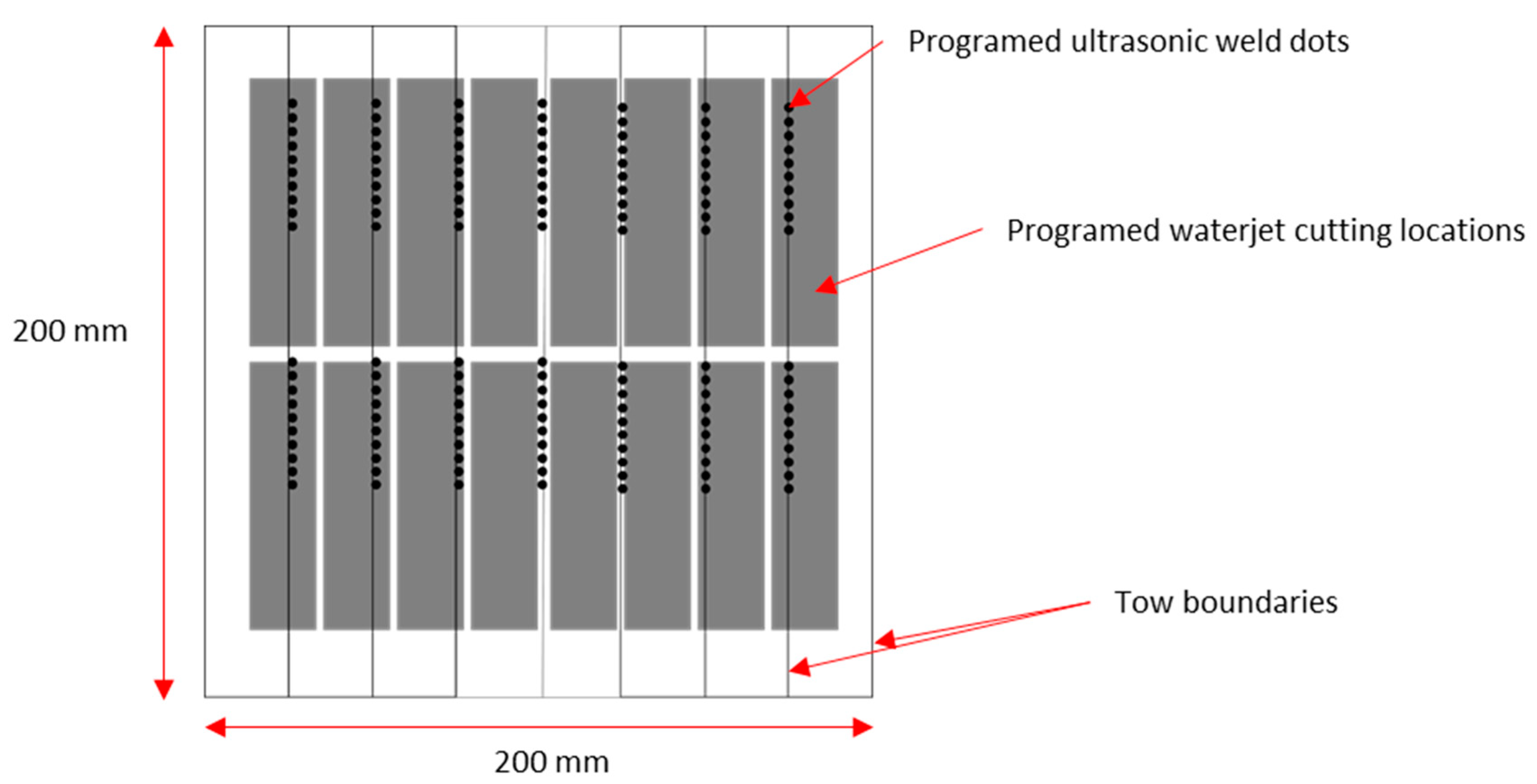
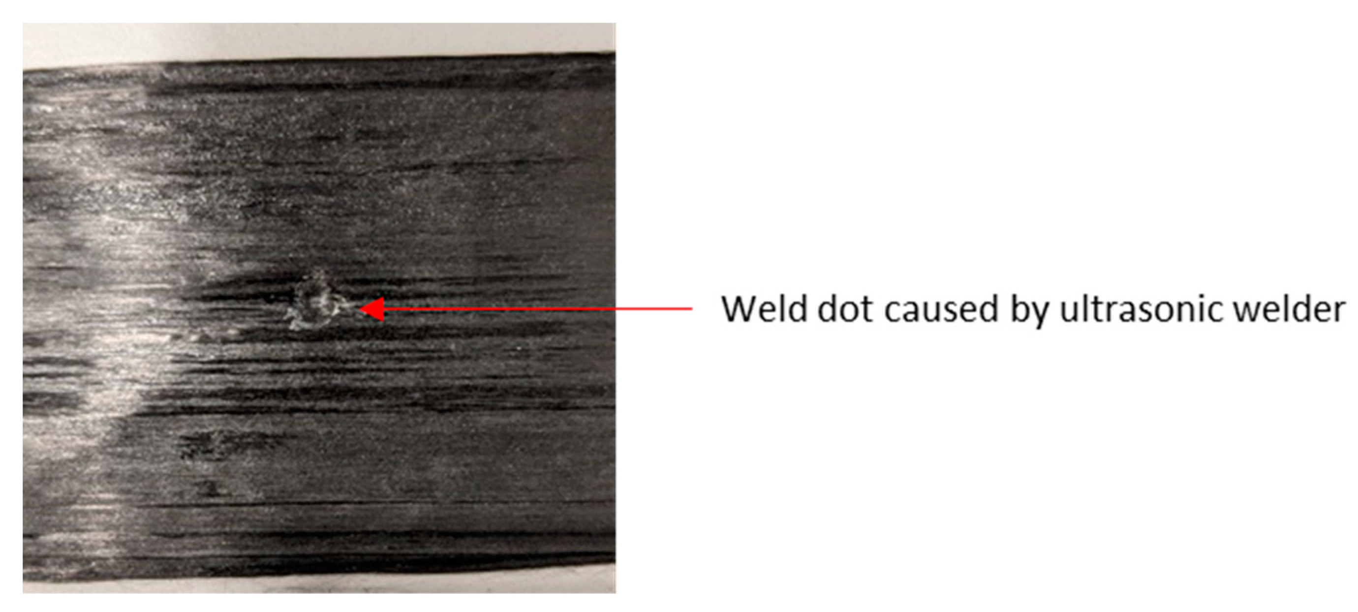
2.3. Tape-Laying Optimisation and Ultrasonic Welding Defect Mitigation

The welding of tape layers prevented fibre movement during laying, allowing the composites to toughen in one stage rather than having to replace the tape cassettes, leading to the rapid laying of both prepreg and dry fibre tapes. Additional defects introduced by the Fill Multilayer were weld spots (as shown in Figure 3), causing an indent in the fabric.
To avoid ultrasonic weld marks and prevent fibre shifting, thermoplastic interlaying was employed. However, during laying with the Fill Multilayer, only ultrasonic welding was performed to prevent lateral movement rather than increasing the mechanical strength. Ultrasonic CFRP welding leads to heating and deformation of the welded layers in thermoplastic matrices [30]. The mitigation of thermosetting polymer degradation during welding has been investigated by Villegas and Rubio [31], who concluded that a higher force and a short heating duration prevent the thermal degradation of epoxy. Tsianhou et al. [32] showed that CF/epoxy composites have good adhesion with an interphase thermoplastic coupling layer to thermoplastic PEEK. Initial testing using GF-PP prepregs showed that using thermoplastic avoided ultrasonic weld damage to the fibres. However, CFRP PP and thermoplastic binders have modulus values inappropriate for most CFRP applications [33]. Using interlayered or interleaved thermoplastic as a tackifier leads to improved load-bearing capabilities [34]. Thermoplastic films, tubes and nanofibres are alternatives that can be used to improve the mechanical performance and as tackifiers for prepregs [35,36]. Typically, these interlayering materials are added to dry fibre and used to improve Mode I and II fracture toughness [37,38] and reduce the delamination area [39,40].

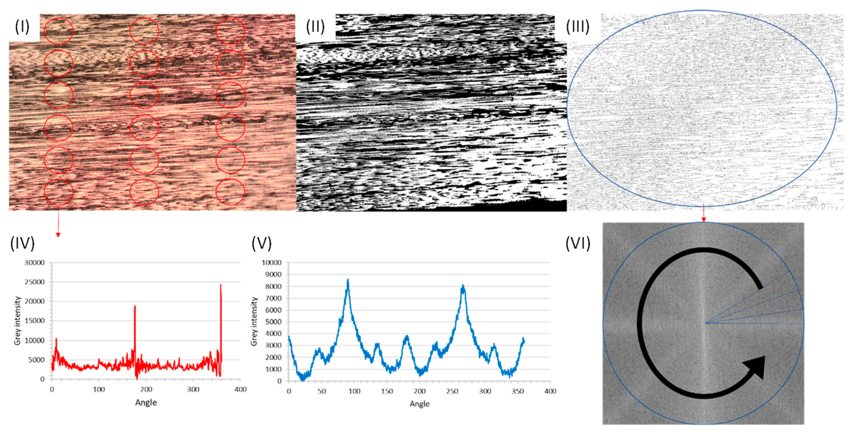
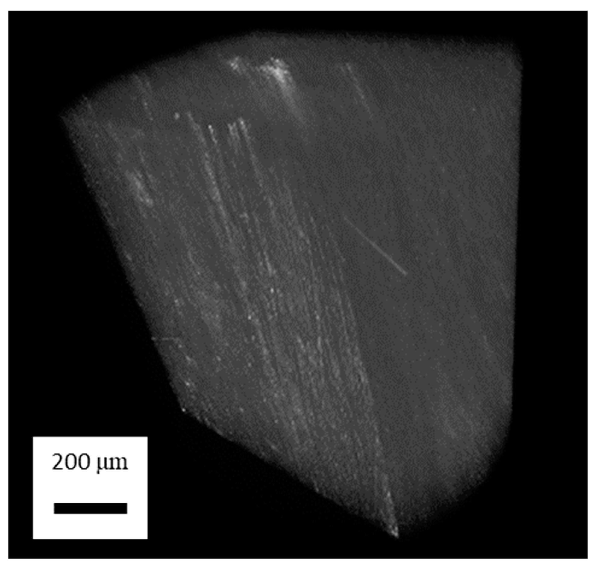
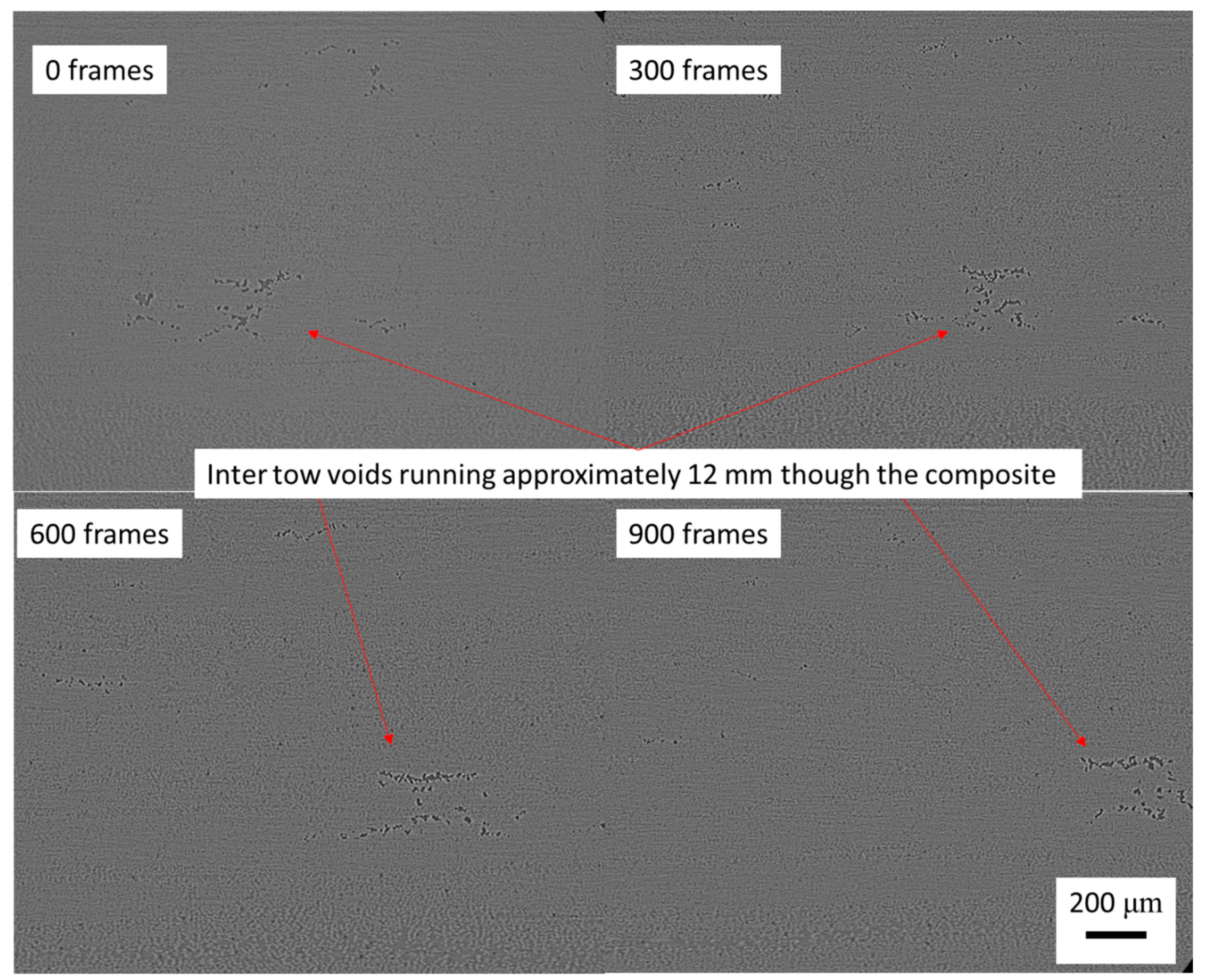
2.4. Optical Investigation of Fibre Alignment and Void Content of CFRP

To analyse random fibre defects due to the tape and fibre misalignment, the Fill Multilayer and hand-laying methods were used to induce a common fibre misalignment across the data set for each type. A BX61 Olympus microscope and Zeiss Supra 40VP SEM micrographs of polished coupons were used to determine the alignment, waviness and defects associated with the hand-laying and Fill Multilayer processes. Figure 4 shows the average fibre misalignment that was used in this research.
Determining the radial sum of the fibre in ImageJ (v.1.54h) gives a grey intensity for the fibre direction for each tow shown in Figure 5 in order to determine the average distribution. To convert the fibres into a binary image, the intensity was selected based on prior void research [41,42]; the grey intensity of fibres was well-defined against the resin and void content, allowing for image skeletonisation to show just the fibres.
Comparing the radial sum of the fibre ply (V) with the individual fibre tow direction (IV) gave the average longitudinal fibre direction and alignment. Using the radial sum of the entire composite gave an accurate estimate of the fibre’s waviness in one direction; the waviness and fibre misalignment were considered to be the same as those of the crimped laminate. In contrast to crimped fabrics, the waviness and alignment of fibres and the fabric may be above 5°. An individual ply radial sum analysis showed the fibre alignment and the waviness (instead of analysing the entire composite, which was the case when using a radial sum analysis, leading to error). The error was due to the circular nature of the radial sum analysis, where the fibre angle was relative to the centre of a circle. Fibres on the edge of the analysis were perpendicular to the centre, thus creating a peak at 90° to the fibre.
The radial sum of each ply was taken from different points to create an average across the composite. The direction of the individual plies and the fibre waviness were determined. The average was taken across the press plate by taking coupons from the centre and edges. Using the same coupons, defects, including ultrasonic weld spots and voids, were analysed using ImageJ™, as shown in Figure 6. The threshold of the void grey intensity has been previously used to accurately measure the void content [43].
Using micro-CT, the void content and fibre alignment of the (45°, 40°, 35°, 30°, 25°, 20°, 15°, 10°, 5°, 0) offset samples were determined. The deliberate offset meant that the fibre angle was unable to be determined in ImageJ, as the fibre was required to be in the 2D plane rather than the quasi-isotropic alignment of the (45°, 40°, 35°, 30°, 25°, 20°, 15°, 10°, 5°, 0) samples. After 3D stacking of the micro-CT images, the void content and fibre alignment could be determined as per the previous method.
The void content was measured using micro-CT and determined through optical images, as shown in Figure 7. The void content measured via micro-CT was 2.017 ± 1.61% on average across the entire coupon, which was lower with a high deviation than that determined via optical imaging due to the higher sample size in micro-CT. There were two regions where this was an issue. Firstly, in the centre of the coupon, weld spots were likely here, increasing the likelihood of artificial defects. Secondly, in the second cut-through on the edge of the coupon, cutting and machining defects associated with tooling were likely to be present in the optical images. Several samples contained tooling defects on the edges of the samples, as determined via micro-CT, which occurred during waterjet cutting. The void concentration was determined to be inter-tow rather than inter-laminar, as the pressing process led to the centre of the tow being the location with the lowest permeability, with resin flows filling the mould cavity and leaving voids in the inter-tow region.

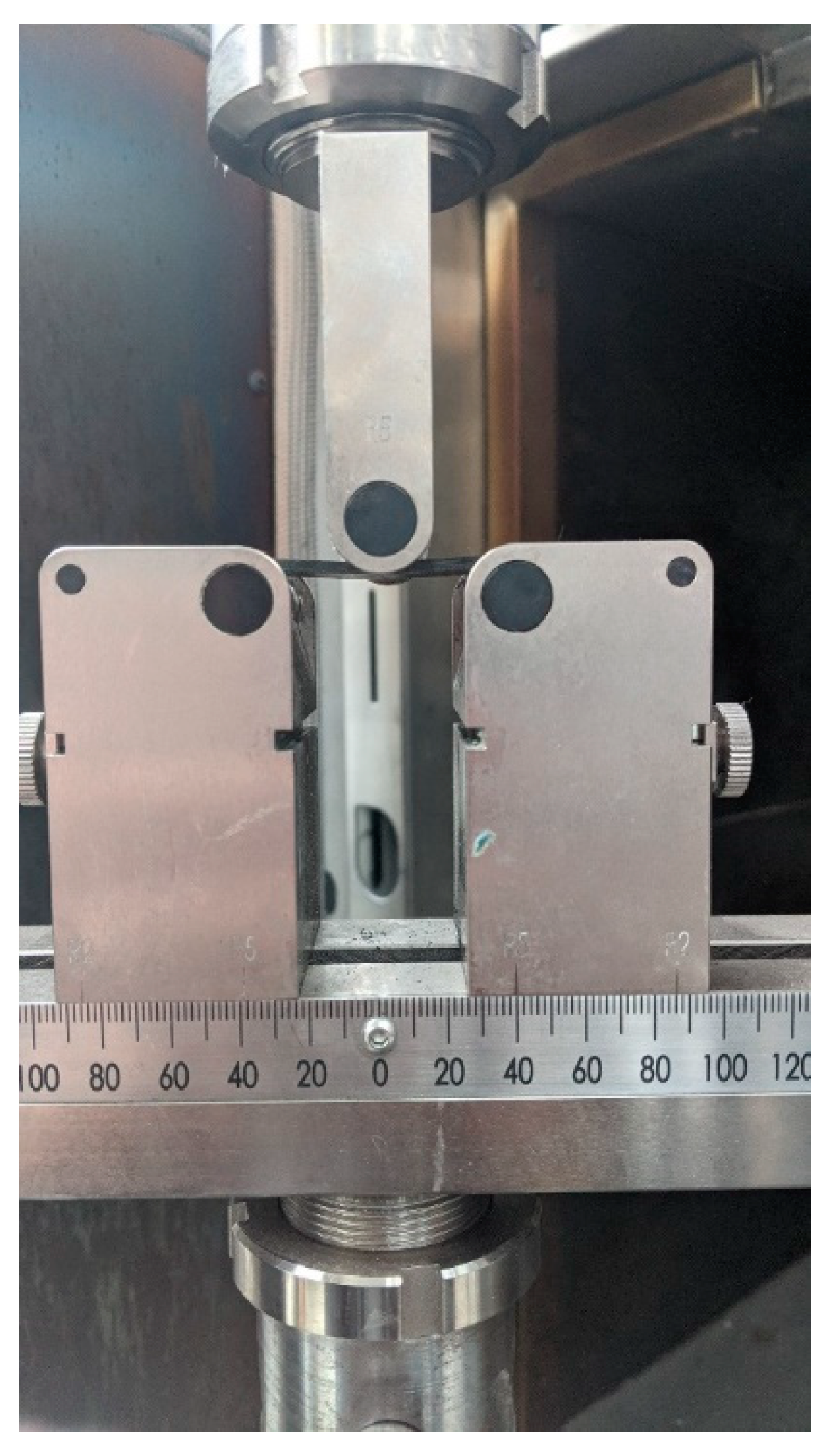
2.5. Three-Point Bending in Cyclic and Quasi-Static Bending Setup

Flexural three-point bending tests with quasi-static cyclic loading were in accordance with ASTM D7264/D7264M–15 [44]. The use of cyclic loading allowed us to investigate the inter-fibre failure (IFF) under fatigue loading, which was the initial stage of fatigue failure [45,46], during which microcracking occurred in the matrix and a drop in the modulus was noted [46].
In the three-point bending tests, a rate of 1 mm/min was used using the Zwick UTM with a 10 kN load cell for quasi-static testing of the flexural modulus using an FLAB-3-11-3LJC-F strain gauge. For cyclic loading, a similar setup was used in an Instron UTM 100 kN load cell, as depicted in Figure 8. The test setup used 10 mm grips on a 40 mm span, satisfying the 1:20 ratio in the ASTM.

2.6. Testing Parameters for Fatigue Loading

To determine the stiffness degradation of the CFRP made in the Fill Multilayer, the CFRP was subjected to 70% of its maximum flexural strength for 4000 three-point bending cycles at 1 Hz. Fatigue testing of composites with minor fabric alignments can create variations in material behaviour, as previously determined by Alam et al. [25]. Blythe et al. [40] showed that matrix cracking occurred within 4000 cycles, after which, the next significant modulus decrease was due to fibre failure. The unidirectional composites were tested with a load of 700 N, while the testing load for the deliberately offset samples was 300 N. The loading was set to 700 N, which was converted from the value in MPa that was determined during quasi-static testing. The preloading condition for both scenarios was 100 N to prevent sample movement during cyclic loading. A constant load of 700 N was chosen to simulate the fixed force experienced by load-bearing structures.

3. Results and Discussion

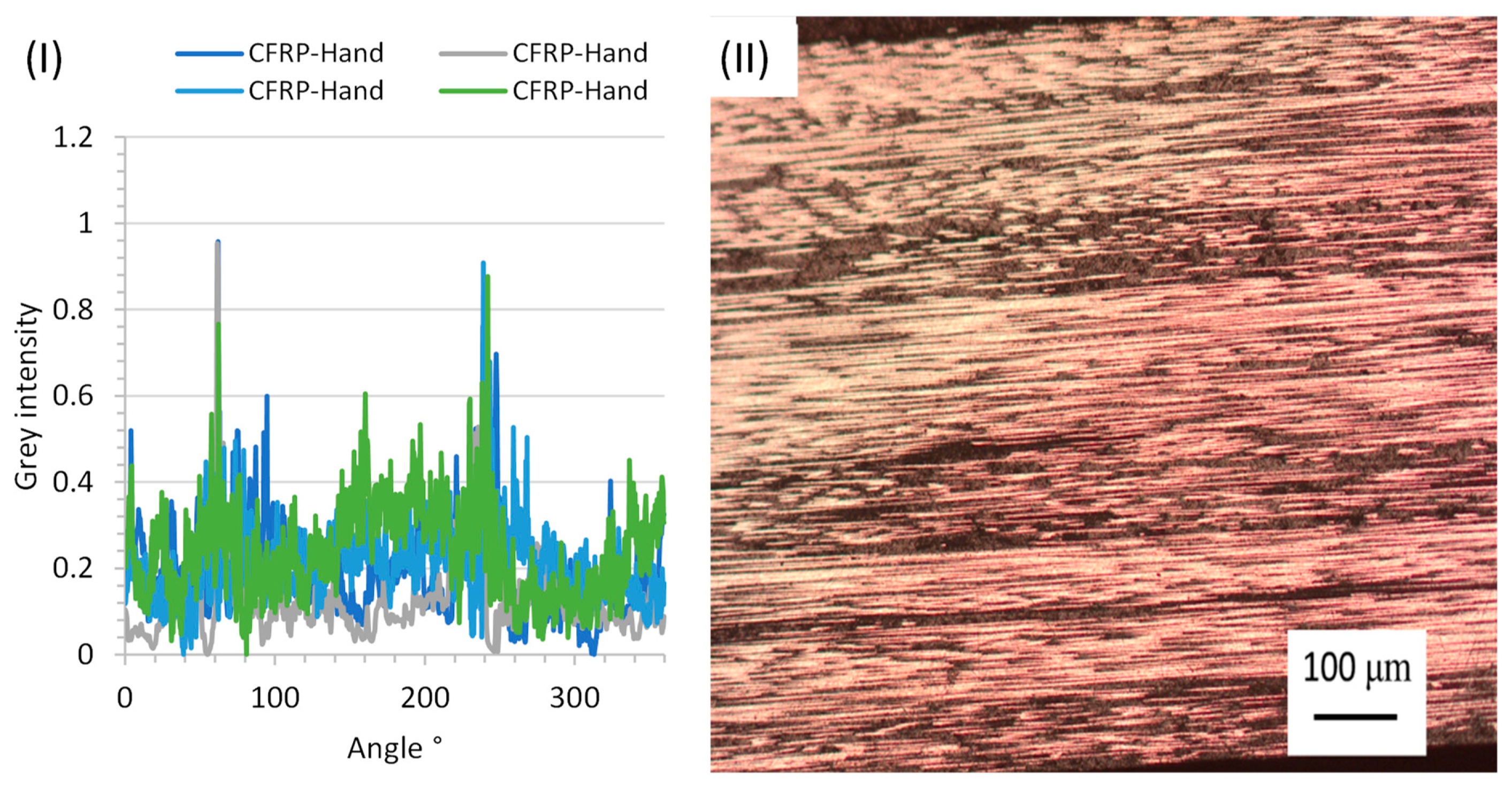
3.1. Waviness Effect of CFRP in Hand-Layered Composites

As a basis for comparison, in this section, off-the-shelf CFRP prepregs and the effect of crimping on alignment and waviness are investigated. Crimped CFRP was deliberately wavy and illustrated the mechanical performance with slight angular defects, as shown in Figure 9. The maximum outliers shown in Figure 9I,II, highlight that the fibre alignment was affected by cross stitching, which is depicted in (IV), showing a misalignment of up to 6.89° measured at Φ.
The resin-rich zones created in crimped CFRP created a wavy pattern. The fibres were then prevented from fully consolidating into a laminate. Instead, a solid crimped fabric existed, which caused a defect zone within the composite laminate, as shown in Figure 9I. There were many different fibre angles present in one localised area due to crimping; this created a random distribution. As other layers were not aligned with the previous layer, the randomness further increased. Machine tooling ensured that the crimping could be distributed evenly across the laminate. However, with hand laying, it was difficult to evenly spread the crimping throughout the laminate. As a result, the fibre angle was ±5.04° and ±5.02° for the crimped fabric. Partial consolidation was achieved between the fibre bundles during pressing; however, resin rich zones were present, as depicted in Figure 10II.

3.2. Alignment of CFRP Fibres Created by Hand Laying and the Fill Multilayer

To analyse the Fill Multilayer’s performance, a comparative study of both static and dynamic three-point bending was conducted. To determine the effect of alignment on the fabric’s mechanical properties, both modulus and flexural strength destructive evaluations of the untested samples were performed. The alignment was measured using radial sum analysis in ImageJ, as shown in Figure 10. Four samples were taken from the outer edges of the plate, and an additional four were taken from the internal plate structure. This was to investigate differences occurring due to edge alignment between the mould and the CFRP plate.
Figure 10. Analysis of the orientation of CFRP fibres produced by hand laying: (I) fibre alignment graph of a row from sample 1 taken from the centre of the test plate; (II) ten CFRP layers from the edge. Images were taken after cutting though an untested sample; fibre orientation images were analysed using ImageJ.
Jcs 08 00092 g010
The radial sum analysis showed that the fabric was more aligned in non-crimped fabric compared with crimped fabric. Crimping induced waviness, with an average fibre alignment of over 5°, and that of the hand-layered samples of only 3.45°. The main cause of misalignment was determined to be ply rotation rather than individual fibre misalignment. One artefact noticeable in the radial sum analysis was the split peak on the ninety-degree side; in Figure 10, the fibres were aligned such that cutting through the fabric removed the fibre ends. In this figure, there are several layers that appear to be aligned in contrast with the other fabric. This was visible in the radial sum analysis, and although it was difficult to quantify the degree of misalignment, the grey intensity was different due to the lack of fibres. Use of the Fill Multilayer led to an expected improvement in the fibre alignment compared with the hand-layered counterpart, with a decrease in the fibre dispersion from 3.45° to 1.68°.
After examining the helix structure, it was determined that a minor fibre scattering of only 1.68° occurred during CFRP-F pressing; thus, the misalignment for a multidirectional composite should have a <2° margin for error. This result shows that the coupons produced in the Fill Multilayer were better aligned and had a greater mechanical strength. As there was greater fibre misalignment between CFRP-Hand, as shown in Figure 10, and CFRP-Fill, as shown in Figure 11, the next step was to analyse the difference in the defects present in these samples. The void concentration was shown to increase after ultrasonic welding, with the average void content increasing by 9.24% from 3.46 ± 0.55% to 3.78 ± 0.58% for CFRP-Hand and CFRP-Fill, respectively. This similarity in the void content suggests that the CFRP-Fill sample was minorly impacted by ultrasonic welding. However, mechanical tests showed that that this was not detrimental to the laminate’s quality. It was anticipated that cross stitching would lead to a larger resin-rich zone for void formation; however, there was no additional void content in this area. From the micro-CT data, it was shown that there were several instances of void formation during ultrasonic welding in the helix structure. Using Image-J, the void content of the thousand image slice was taken to accurately determine the void content for the centre of the structure.

3.3. Alignment of Fibre Stacks at Different Layup Orientations

To test the alignment performance of the Fill Multilayer, a bioinspired helicoidal structure was created with a tape offset of 5°. This helicoidal structure, based on Bouligand structures, has been shown to have an improved impact resistance [47,48,49,50] and would serve to showcase the Fill Multilayer’s laying accuracy. The improved impact resistance could be attributed to the coupled effects of the fibre offset (1° to 25°) and spiral stacking sequence, which resulted in a longer crack propagation path. A helicoidal structure can be developed via automatic tape laying at a 5° offset. The structure’s behaviour was tested alongside the accuracy of the machine’s placement. There was a problem with low-angle fibre offsets, as the fibre tolerance needed to be high to stop gaps from occurring within the fibre stacks.
Assuming that the Fill Multilayer had a margin of error of ~1.26°, it was expected that a helix structure that was layered every 5° would result in fibre alignment of 4° to 6°. Figure 12 shows that ultrasonic welding produced a void concentration below the tape, assuming some tow splitting, which resulted in the resin being partially cured; this then created inter-tow voids during curing.
Figure 12I shows the effect of improper consolidation on the centrepiece (the fibre contained voids). An increase in void concentration could be observed from the micro-CT results shown in Figure 13, where the fibre exhibited divots caused by compression of the fibres using an ultrasonic weld horn. The divot in the CFRP prepreg resulted in a semicircular displacement of the resin, and it was shown via CT that this displacement caused voids under the divot area. The preform was held together with resin; therefore, the only fabric characteristics affecting the fibre geometry in the Z direction were fibre nesting and ultrasonic weld spots. Ultrasonic weld spots were difficult to detect by examining cross sections; instead, micro-CT images of the entire sample were taken and are shown in Figure 13.
The initial micro-CT images shown in Figure 13 show that the majority of the void contents in the material were positioned between the tapes. The tape and inter-tape voids were likely a result of gaps in the tape, which were formed by compressed trapped air. The image slices were stacked in the XZ axis, as shown in Figure 14, allowing for a radial sum analysis of the (45°, 40°, 35°, 30°, 25°, 20°, 15°, 10°, 5°, 0) offsets.
From the images, it is clear that the coupon edges were minorly damaged due to the cutting process with deliberate misalignments. Several cracks ran from the voids to the edges, resulting in pre-cracked coupons. The XZ images were used to generate the radial sum plot shown in Figure 15.
The fibre alignment of the (45°, 40°, 35°, 30°, 25°, 20°, 15°, 10°, 5°, 0) samples was determined to be 2.21°. This increase, compared with the UD fabrics, suggests that tape misalignment increased as the fibres were pressed. This was expected as the fibres were moving over one another, becoming wavey, and the fibres were unable to nest without being bent.

3.4. Quasi-Static Three-Point Bending of CFRP-UD Fabrics

As in the hand-laying method, a sheet of CFRP prepreg and not tape was used so that no gaps or ultrasonic weld marks could form. It was expected then that these defects would not be present in samples produced via hand laying compared with those produced via the Fill Multilayer. The change in the CFRP-Hand samples was shown to be less than that of the CFRP-Fill samples.
The hand-layered CFRP-Hand samples had a similar flexural strength maximum, as shown in Figure 16. The samples produced using the Fill Multilayer exhibited a higher flexural strength than that of the hand-layered samples, with an average of 1218.57 ± 78.85 MPa compared with 1116.59 ± 82.39 MPa, taken from Figure 17. No observable difference in the failure mechanism was found between the CFRP-Hand and CFRP-Fill samples.
The main issue with the Fill Multilayer machine was the high deviation in the flexural strength of 78.85 MPa, which was higher than that of the hand-layered samples. This deviation was investigated to determine whether the result was due to ultrasonic welding marks occurring under the machine head (out of the cut 18 samples, 4 should be free from ultrasonic welding marks). During testing, it was shown that minor premature failure occurred in samples with ultrasonic weld spots. This sample inconsistency led to the use of a thermoplastic nanofibre inter-layer to attempt to reduce the weld defects. Additionally, this failure could be due to gaps between the tape, as alternating tapes would wither and thus a weld mark or gap would appear.
The failure mechanisms of the UD samples shown in Figure 18 showed that both Fill multiplayer samples failed due to compression failure turning into inter-laminar delamination, as expected. From microscopy performed on the Fill Multilayer samples, it was clear that the failure of both samples initiated due to buckling of the first carbon fibre layer, which then propagated into inter-laminar failure.

3.5. Tape-Laying Accuracy at Different Fibre Angles

In deliberately offset samples, the stress–strain response exhibited a more pseudo-ductile response than that of the brittle UD samples. Rotation around the fibre angle produced a flattened peak response in the crack propagation, as shown in Figure 18.
The response showed that the (0°, 5°, 10°, 15°, 20°, 25°, 30°, 35°, 40°, 45°) CFRP underwent catastrophic failure due to failure of the compression layer’s UD fabric. In the (45°, 40°, 35°, 30°, 25°, 20°, 15°, 10°, 5°, 0) sample, the UD fabric under tension was aligned, resulting in a higher flexural strength.
This investigation into the flexural strength and angle of alignment demonstrated an exponential relationship between the fibre alignment and flexural strength. It is important to note that a unidirectional fabric was assumed in the (0°, 5°, 10°, 15°, 20°, 25°, 30°, 35°, 40°, 45°) helix sample with the characteristics of a single carbon layer under compression. The reverse sample, as depicted in Figure 18, had a significantly higher flexural strength than the 0° fibre angle sample under compression.
From Figure 18, an average flexural strength of 487.70 ± 53.23 MPa for helix-CFRP could be determined. The (45°, 40°, 35°, 30°, 25°, 20°, 15°, 10°, 5°, 0) samples had flexural strengths of 204.08 MPa and 245.62 MPa. The pseudo-ductile behaviour was examined via microscopy, and it was determined that the failure of the material was very similar to that of the helicoidal structure. As with the helicoidal structure, crack propagation was deflected by the low angle of reinforcement around the fibres. The resulting failure was delamination and inter-fibre failure, as shown in Figure 19.
There was little difference between the failure mechanisms of the helix-CFRP and the control samples. All samples exhibited significant fibre propagation in the inter-fibre region due to the change in fibre direction. This resulted in extensive inter-fibre delamination between fibres, as shown in Figure 20.

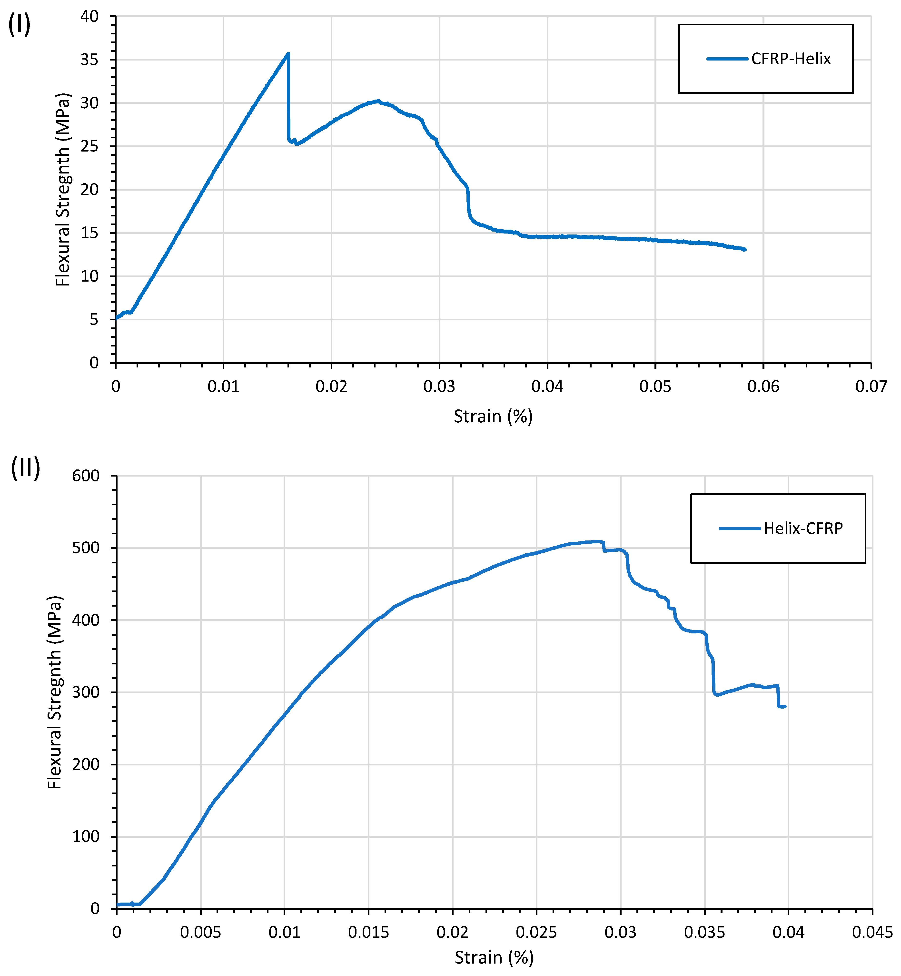
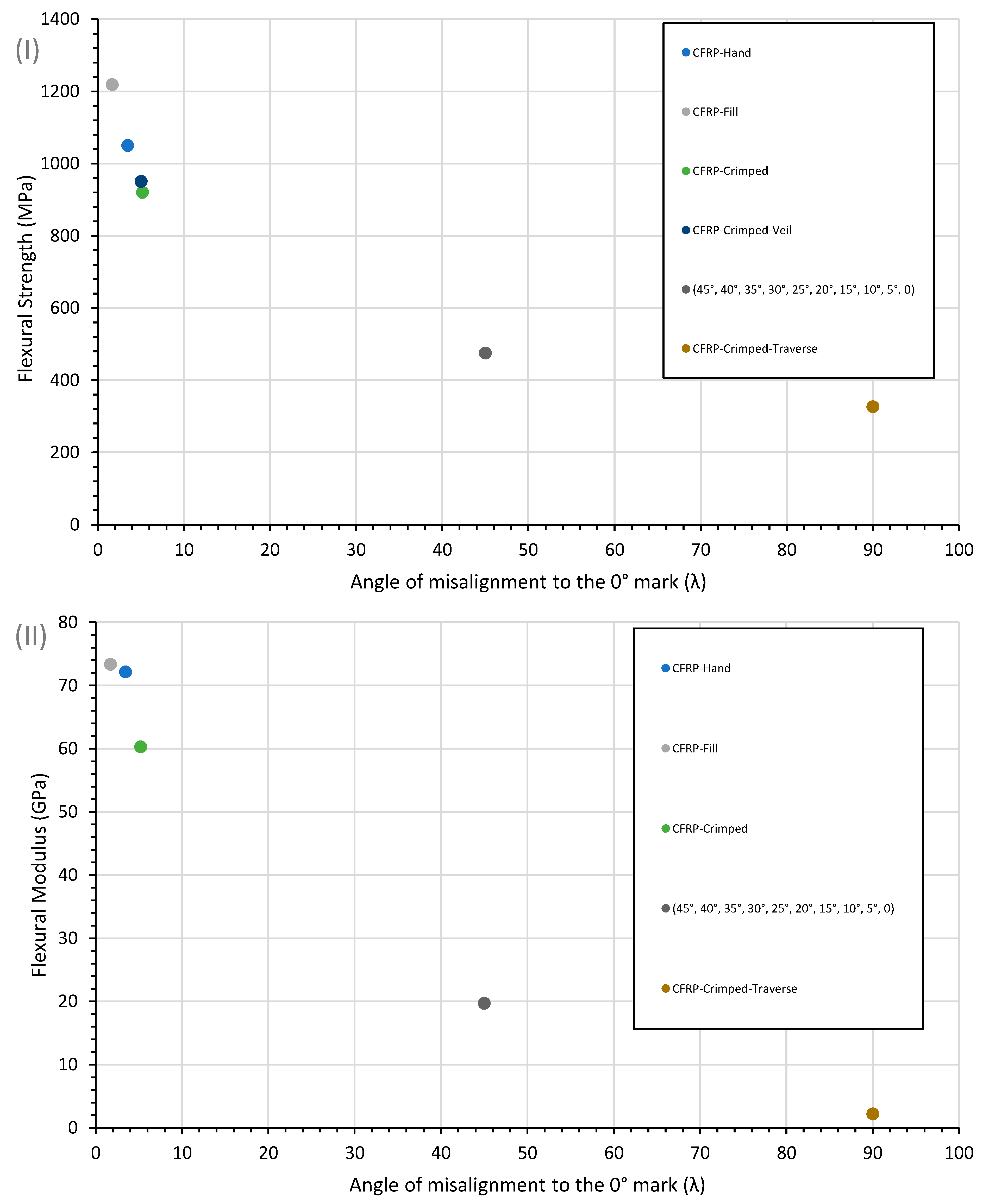
3.6. Examination of the Flexural Strength at Different Fibre Misalignment Angles

The resulting fibre alignment and void characteristics are shown in Table 2. The hand-layered CFRP plies exhibited a fibre misalignment of 0° ± 3.5° in the in-plane direction after curing, as shown in Table 2. A potential flaw found in the Fill Multilayer process was the ultrasonic welding step, which caused a section of epoxy to be cured and fibre waviness to occur. Initial imaging showed that the fibres were pushed out from the centre of the weld spot, causing a resin-rich centre under the welder horn. Tow splitting in the y-direction, as seen in Figure 12, was a contributing factor to misalignment in the x-direction.
The alignment of the fabric differed between hand-layered CFRP and that layered by the machine. The deliberately offset fabric had a higher misalignment angle than the CFRP-Fill sample. It was anticipated that the compression process would result in fibres rotating to nest in one another, as well as waviness during compression, hence the higher angle of misalignment compared with the UD samples. During processing in the Fill Multilayer, the tape became the limiting factor, affecting random fibre alignment. There were several issues with the tape, such as splitting of the toes before spooling and prepreg sliding due to friction and pressing. To determine the effect of fibre alignment, a hand-layered sample was compared with a Fill Multilayer-manufactured sample under identical curing conditions. As a further reference, a hand-layered crimped UD fabric was studied. The resulting average flexural strength and modulus were recorded for each sample, as shown in Table 2. The angle of fibre misalignment was measured at different flexural strengths, as shown in Figure 21, showing the exponential relationship between the fibre angle and the flexural strength.
The logarithmic relationship between the CFRP alignment and fibres shown in Figure 21 indicated that, despite the cross stitching, the material properties obtained by aligning the fibres manually could be reliably predicted. However, this relationship was not true for the (0°, 5°,10°, 15°, 20°, 25°, 30°, 35°, 40°, 45°) stacking order, only the reverse. The lower limit of the yield point perpendicular to the fibre angle was determined by the resin’s flexural characteristics. The upper limit of the composite was determined by the maximum tensile strength.

3.7. Dynamic Testing of CFRP

To determine the shear stress in the presence of fibre misalignment in the matrix, which is the main cause of matrix cracking, a comparison of cross-stitched CFRP to non-crimped CFRP was performed to determine the effects of waviness on the fibre. Initial matrix cracking was visible around the cross stitches, as the matrix-rich areas were prone to crack initiation. Compared with the CFRP without stitching, a higher flexural modulus was determined via quasi-static testing. It was expected that, due to higher misalignment, the hand-layered material would have more matrix cracks and the Fill-CFRP sample would have a higher stiffness retention.
During quasi-static tests, the strain behaviour was dominated by the modulus of the CFRP-Fill and CFRP-Hand samples, with values of 73.33 GPa and 72.15 GPa, respectively. However, the stress–strain behaviour was correlated with the fibre alignment, with Fill samples having a higher strain of 0.008% compared with 0.006% for hand-layered samples. The failure mechanism that led to this nonlinear behaviour is shown in Figure 22. The majority of CFRP-H samples exhibited ply delamination in the compression layer; this also occurred in quasi-static testing.
The failure of the crimped and non-crimped fabrics in both static and dynamic testing clearly indicated the difference in flexural strength. In CFRP-Crimped samples, failure occurred via block crack propagation compared with the delamination occurring between plies in CFRP-Fill and CFRP-Hand samples. Delamination caused a larger drop in the modulus compared with CFRP-Crimped. After 4000 cycles, the modulus of CFRP-Hand was 54 GPa ± 1.98 GPa.
The UD CFRP samples all exhibited little stiffness degradation after 4000 cycles at 70% of the maximum loading, with the lowest occurring for CFRP-Fill at less than 3% across the data set, as shown in Figure 23.
The non-crimped fabric produced via the Fill Multilayer exhibited a smaller flexural modulus decrease compared with hand-layered samples, as shown in Figure 24. A decrease in the fibre alignment led to a greater stiffness retention in these samples compared with hand-layered samples. The reproducibility of the CFRP-Fill samples was significantly higher than the other samples, suggesting minimal manufacturing defects. The zero-tack resin used in the CFRP in the Fill Multilayer required a five-minute curing time. However, when the fibre alignment was as low as 1.68, the shear stress affected the matrix and thus large longitudinal delamination occurred. Compared with the Fill Multilayer-produced samples, the stiffness loss was minimal, with an average drop of 1.4% in the modulus after cycling.

4. Conclusions

Fibre alignment was shown as the lead cause of matrix cracking, as poor alignment led to fibre shearing. The Fill Multilayer machine produced UD composites with an alignment of ±1.26°, lower in comparison with hand-layered composites, which had a minimum alignment of ±3.45°. Minimal misalignment occurred due to the Fill Multilayer, leading to a higher flexural strength, with inter-laminar failure occurring on the tension side. Compression failure in the hand-layered samples resulted in significant delamination and buckling. The cracks continued to propagate after their initial formation, with significant loading retention.
The improved fibre alignment of samples manufactured by the Fill Multilayer led to significant improvements in the flexural strength. With the Fill Multilayer, an improvement in the fibre alignment compared with hand laying was observed, showing a better reproducibility. The deviation in Fill Multilayer samples was high due to several processing issues and the effects of ultrasonic welding. In the microscopy cross sections, there was a high concentration of voids within the inter-tow region of the fabrics. During ultrasonic welding, a divot occurred within fabrics with a higher alignment; this had a minimal impact on the laminate. The void content in handmade and Fill Multilayer-produced CFRP was 3.46% and 3.75% in this study. As the void content was within the standard deviation of the Fill Multilayer-produced coupons, it was concluded that ultrasonic welding had only a minor effect on the void content. The increase in void concentration was consistent with the prior literature.
The main manufacturing defects were rolling and unrolling, as the Fill Multilayer had a tape width threshold of ±0.05 mm, which resulted in a low fibre alignment as the tooling became the limiting factor affecting the fabric alignment. Random alignment was limited by the Fill Multilayer machine, with the tolerances for the roll and tape being a limiting factor in alignment. It is therefore necessary to identify the machine tolerances when predicting fibre alignment. In addition to investigating these machine tolerances, in situ process monitoring and modelling also have great potential in future work.

Author Contributions

Methodology, A.B.; conceptualisation, A.B.; writing—original draft preparation A.B., M.N. and B.X.C.; writing—review and editing, A.B., M.N., B.E. and B.X.C.; supervision, B.F., M.N. and B.E. All authors have read and agreed to the published version of the manuscript.

Funding

This research was funded by Ford Motor Company, grant number URP2016-4010R.

Data Availability Statement

Data are available upon request.

Conflicts of Interest

The authors declare no conflicts of interest. The funders had no role in the design of the study; in the collection, analyses, or interpretation of data; in the writing of the manuscript; or in the decision to publish the results.

References

  1. Blythe, A.; Fox, B.; Nikzad, M.; Eisenbart, B.; Chai, B.X.; Blanchard, P.; Dahl, J. Evaluation of the Failure Mechanism in Polyamide Nanofibre Veil Toughened Hybrid Carbon/Glass Fibre Composites. Materials 2022, 15, 8877. [Google Scholar] [CrossRef] [PubMed]
  2. Chai, B.X.; Eisenbart, B.; Nikzad, M.; Fox, B.; Blythe, A.; Bwar, K.H.; Wang, J.; Du, Y.; Shevtsov, S. Application of KNN and ANN Metamodeling for RTM Filling Process Prediction. Materials 2023, 16, 6115. [Google Scholar] [CrossRef] [PubMed]
  3. Chai, B.X.; Eisenbart, B.; Nikzad, M.; Fox, B.; Wang, Y.; Bwar, K.H.; Zhang, K. Review of Approaches to Minimise the Cost of Simulation-Based Optimisation for Liquid Composite Moulding Processes. Materials 2023, 16, 7580. [Google Scholar] [CrossRef] [PubMed]
  4. Shevtsov, S.; Zhilyaev, I.; Chang, S.H.; Wu, J.K.; Snezhina, N. Multi-Criteria Decision Approach to Design a Vacuum Infusion Process Layout Providing the Polymeric Composite Part Quality. Polymers 2022, 14, 313. [Google Scholar] [CrossRef] [PubMed]
  5. Rodrigues, H.; Arêde, A.; Furtado, A.; Rocha, P. Seismic behavior of strengthened RC columns under biaxial loading: An experimental characterization. Constr. Build. Mater. 2015, 95, 393–405. [Google Scholar] [CrossRef]
  6. Rodrigues, H.; Arêde, A.; Furtado, A.; Rocha, P. Seismic Rehabilitation of RC Columns Under Biaxial Loading: An Experimental Characterization. Structures 2015, 3, 43–56. [Google Scholar] [CrossRef]
  7. Zhilyaev, I.; Chang, S.-H.; Shevtsov, S.; Snezhina, N. Preform Porosity and Final Thickness Variability Prediction after Controlled Post-Infusion External Pressure Application with the FEA Model. J. Compos. Sci. 2022, 6, 361. [Google Scholar] [CrossRef]
  8. Djavadifar, A.; Graham-Knight, J.B.; Kӧrber, M.; Lasserre, P.; Najjaran, H. Automated visual detection of geometrical defects in composite manufacturing processes using deep convolutional neural networks. J. Intell. Manuf. 2022, 33, 2257–2275. [Google Scholar] [CrossRef]
  9. Mehdikhani, M.; Gorbatikh, L.; Verpoest, I.; Lomov, S.V. Voids in fiber-reinforced polymer composites: A review on their formation, characteristics, and effects on mechanical performance. J. Compos. Mater. 2019, 53, 1579–1669. [Google Scholar] [CrossRef]
  10. Gokce, A.; Advani, S.G. Simultaneous gate and vent location optimization in liquid composite molding processes. Compos. Part A Appl. Sci. Manuf. 2004, 35, 1419–1432. [Google Scholar] [CrossRef]
  11. Falk, H.; Christian, W. Manufacturing-Induced Imperfections in Composite Parts Manufactured via Automated Fiber Placement. J. Compos. Sci. 2019, 3, 56. [Google Scholar] [CrossRef]
  12. Oromiehie, E.; Prusty, B.G.; Compston, P.; Rajan, G. Automated fibre placement based composite structures: Review on the defects, impacts and inspections techniques. Compos. Struct. 2019, 224, 110987. [Google Scholar] [CrossRef]
  13. Belnoue, J.P.H.; Mesogitis, T.; Nixon-Pearson, O.J.; Kratz, J.; Ivanov, D.S.; Partridge, I.K.; Potter, K.D.; Hallett, S.R. Understanding and predicting defect formation in automated fibre placement pre-preg laminates. Compos. Part A Appl. Sci. Manuf. 2017, 102, 196–206. [Google Scholar] [CrossRef]
  14. FILL Multilayer. Available online: https://www.fill.co.at/en/products/multilayer (accessed on 6 November 2023).
  15. Yadav, N.; Schledjewski, R. Review of in-process defect monitoring for automated tape laying. Compos. Part A Appl. Sci. Manuf. 2023, 173, 107654. [Google Scholar] [CrossRef]
  16. Sacco, C.; Baz Radwan, A.; Anderson, A.; Harik, R.; Gregory, E. Machine learning in composites manufacturing: A case study of Automated Fiber Placement inspection. Compos. Struct. 2020, 250, 112514. [Google Scholar] [CrossRef]
  17. Li, H.; Chen, C.; Yi, R.; Li, Y.; Wu, J. Ultrasonic welding of fiber-reinforced thermoplastic composites: A review. Int. J. Adv. Manuf. Technol. 2022, 120, 29–57. [Google Scholar] [CrossRef]
  18. Boros, R.; Sibikin, I.; Ageyeva, T.; Kovács, J.G. Development and Validation of a Test Mold for Thermoplastic Resin Transfer Molding of Reactive PA-6. Polymer 2020, 12, 976. [Google Scholar] [CrossRef]
  19. Crossley, R.J.; Schubel, P.J.; De Focatiis, D.S.A. Time–temperature equivalence in the tack and dynamic stiffness of polymer prepreg and its application to automated composites manufacturing. Compos. Part A Appl. Sci. Manuf. 2013, 52, 126–133. [Google Scholar] [CrossRef]
  20. Croft, K.; Lessard, L.; Pasini, D.; Hojjati, M.; Chen, J.; Yousefpour, A. Experimental study of the effect of automated fiber placement induced defects on performance of composite laminates. Compos. Part A Appl. Sci. Manuf. 2011, 42, 484–491. [Google Scholar] [CrossRef]
  21. Jeppesen, N.; Mikkelsen, L.P.; Dahl, A.B.; Christensen, A.N.; Dahl, V.A. Quantifying effects of manufacturing methods on fiber orientation in unidirectional composites using structure tensor analysis. Compos. Part A Appl. Sci. Manuf. 2021, 149, 106541. [Google Scholar] [CrossRef]
  22. Bodaghi, M.; Vanaerschot, A.; Lomov, S.V.; Correia, N.C. On the variability of mesoscale permeability of a 2/2 twill carbon fabric induced by variability of the internal geometry. Compos. Part A Appl. Sci. Manuf. 2017, 101, 394–407. [Google Scholar] [CrossRef]
  23. Bunea, M.; Bria, V.; Silva, F.S.; Birsan, I.G.; Buciumeanu, M. Influence of Fiber Orientation and Fillers on Low Velocity Impact Response of the Fabric Reinforced Epoxy Composites. Appl. Compos. Mater. 2021, 28, 1277–1290. [Google Scholar] [CrossRef]
  24. Nugroho, G.; Budiyantoro, C. Optimization of Fiber Factors on Flexural Properties for Carbon Fiber Reinforced Polypropylene. J. Compos. Sci. 2022, 6, 160. [Google Scholar] [CrossRef]
  25. Alam, P.; Mamalis, D.; Robert, C.; Floreani, C.; Ó Brádaigh, C.M. The fatigue of carbon fibre reinforced plastics—A review. Compos. Part B Eng. 2019, 166, 555–579. [Google Scholar] [CrossRef]
  26. Chai, B.X.; Eisenbart, B.; Nikzad, M.; Fox, B.; Blythe, A.; Blanchard, P.; Dahl, J. A novel heuristic optimisation framework for radial injection configuration for the resin transfer moulding process. Compos. Part A Appl. Sci. Manuf. 2023, 165, 107352. [Google Scholar] [CrossRef]
  27. Capricho, J.C.; Subhani, K.; Chai, B.X.; Bryant, G.; Salim, N.; Juodkazis, S.; Fox, B.L.; Hameed, N. Porous macroradical epoxy-based supercapacitors. Polymer 2022, 259, 125356. [Google Scholar] [CrossRef]
  28. Seyednourani, M.; Yildiz, M.; Sas, H.S. A two-stage optimization methodology for gate and vent locations and distribution media layout for liquid composite molding process. Compos. Part A Appl. Sci. Manuf. 2021, 149, 106522. [Google Scholar] [CrossRef]
  29. Li, J.; Zhang, C.; Liang, R.; Wang, B. Robust design of composites manufacturing processes with process simulation and optimisation methods. Int. J. Prod. Res. 2008, 46, 2087–2104. [Google Scholar] [CrossRef]
  30. Wang, Y.; Rao, Z.; Liao, S.; Wang, F. Ultrasonic welding of fiber reinforced thermoplastic composites: Current understanding and challenges. Compos. Part A Appl. Sci. Manuf. 2021, 149, 106578. [Google Scholar] [CrossRef]
  31. Fernandez Villegas, I.; Vizcaino Rubio, P. On avoiding thermal degradation during welding of high-performance thermoplastic composites to thermoset composites. Compos. Part A Appl. Sci. Manuf. 2015, 77, 172–180. [Google Scholar] [CrossRef]
  32. Tsiangou, E.; Kupski, J.; Teixeira de Freitas, S.; Benedictus, R.; Villegas, I.F. On the sensitivity of ultrasonic welding of epoxy- to polyetheretherketone (PEEK)-based composites to the heating time during the welding process. Compos. Part A Appl. Sci. Manuf. 2021, 144, 106334. [Google Scholar] [CrossRef]
  33. Terekhov, I.V.; Chistyakov, E.M. Binders used for the manufacturing of composite materials by liquid composite molding. Polymers 2021, 14, 87. [Google Scholar] [CrossRef]
  34. Bhudolia, S.K.; Gohel, G.; Leong, K.F.; Joshi, S.C. Damping, impact and flexural performance of novel carbon/Elium® thermoplastic tubular composites. Compos. Part B Eng. 2020, 203, 108480. [Google Scholar] [CrossRef]
  35. Dong, C. Flexural behaviour of carbon and glass reinforced hybrid composite pipes. Compos. Part C Open Access 2021, 4, 100090. [Google Scholar] [CrossRef]
  36. Wang, Y.; Emerson, M.J.; Conradsen, K.; Dahl, A.B.; Dahl, V.A.; Maire, E.; Withers, P.J. Evolution of fibre deflection leading to kink-band formation in unidirectional glass fibre/epoxy composite under axial compression. Compos. Sci. Technol. 2021, 213, 108929. [Google Scholar] [CrossRef]
  37. Quan, D.; Yue, D.; Ma, Y.; Zhao, G.; Alderliesten, R. On the mix-mode fracture of carbon fibre/epoxy composites interleaved with various thermoplastic veils. Compos. Commun. 2022, 33, 101230. [Google Scholar] [CrossRef]
  38. Tsotsis, T.K. Interlayer toughening of composite materials. Polym. Compos. 2009, 30, 70–86. [Google Scholar] [CrossRef]
  39. Cheng, C.; Zhang, C.; Zhou, J.; Jiang, M.; Sun, Z.; Zhou, S.; Liu, Y.; Chen, Z.; Xu, L.; Zhang, H.; et al. Improving the interlaminar toughness of the carbon fiber/epoxy composites via interleaved with polyethersulfone porous films. Compos. Sci. Technol. 2019, 183, 107827. [Google Scholar] [CrossRef]
  40. Blythe, A.; Fox, B.; Nikzad, M.; Eisenbart, B.; Chai, B.X. Stiffness Degradation under Cyclic Loading Using Three-Point Bending of Hybridised Carbon/Glass Fibres with a Polyamide 6,6 Nanofibre Interlayer. J. Compos. Sci. 2022, 6, 270. [Google Scholar] [CrossRef]
  41. Sebaey, T.A.; Bouhrara, M.; O’Dowd, N. Fibre Alignment and Void Assessment in Thermoplastic Carbon Fibre Reinforced Polymers Manufactured by Automated Tape Placement. Polymers 2021, 13, 473. [Google Scholar] [CrossRef]
  42. Kratmann, K.K.; Sutcliffe, M.P.F.; Lilleheden, L.T.; Pyrz, R.; Thomsen, O.T. A novel image analysis procedure for measuring fibre misalignment in unidirectional fibre composites. Compos. Sci. Technol. 2009, 69, 228–238. [Google Scholar] [CrossRef]
  43. Santulli, C.; Gil, R.G.; Long, A.C.; Clifford, M.J. Void Content Measurements in Commingled E-Glass/Polypropylene Composites Using Image Analysis from Optical Micrographs. Sci. Eng. Compos. Mater. 2002, 10, 77–90. [Google Scholar] [CrossRef]
  44. D7264/D7264M-15; Standard Test Method for Flexural Properties of Polymer Matrix Composite Materials. ASTM International: Newark, DE, USA, 2015.
  45. Brod, M.; Dean, A.; Scheffler, S.; Gerendt, C.; Rolfes, R. Numerical modeling and experimental validation of fatigue damage in Cross-Ply CFRP composites under inhomogeneous stress states. Compos. Part B Eng. 2020, 200, 108050. [Google Scholar] [CrossRef]
  46. Stinchcomb, W.W.; Bakis, C.E. Chapter 4—Fatigue Behavior of Composite Laminates. In Composite Materials Series; Reifsnider, K.L., Ed.; Elsevier: Amsterdam, The Netherlands, 1991; Volume 4, pp. 105–180. [Google Scholar]
  47. Pinto, F.; Iervolino, O.; Scarselli, G.; Ginzburg, D.; Meo, M. Bioinspired Twisted Composites Based on Bouligand Structures; SPIE: Bellingham, WA, USA, 2016; p. 97970E-E-13. [Google Scholar]
  48. Apichattrabrut, T.; Ravi-Chandar, K. Helicoidal Composites. Mech. Adv. Mater. Struct. 2006, 13, 61–76. [Google Scholar] [CrossRef]
  49. Qin, X.; Marchi, B.C.; Meng, Z.; Keten, S. Impact resistance of nanocellulose films with bioinspired Bouligand microstructures. Nanoscale Adv. 2019, 1, 1351–1361. [Google Scholar] [CrossRef] [PubMed]
  50. Cheng, L.; Thomas, A.; Glancey, J.L.; Karlsson, A.M. Mechanical behavior of bio-inspired laminated composites. Compos. Part A Appl. Sci. Manuf. 2011, 42, 211–220. [Google Scholar] [CrossRef]
Figure 1. Reference photo of the Fill Multilayer during tape-laying operations and CFRP winding from a roll to a cassette.
Jcs 08 00092 g001
Figure 2. CFRP layered using the Fill Multilayer (10 layers) for (0°)10 UD fabric. Each increment on the side is 50 mm, for a total internal machine diameter of 2250 mm2. Black lines represent the probable weld mark locations and black dots represent the programmed areas where ultrasonic weld dots occur during laying.
Jcs 08 00092 g002
Figure 3. Ultrasonic weld spot on two layers of uncured CFRP welded at ten joules for one second.
Jcs 08 00092 g003
Figure 4. Diagram of fibre measurements in the x direction. Angle Φ measured for deviation from a 0° fibre.
Jcs 08 00092 g004
Figure 5. Method used for ImageJ analysis of the fibre waviness and misalignment during testing. (I) Cut through of CFRP Fill mounted in optical resin; (II) 2D image made binary; (III) 2D image skeletonised so only the edges are visible; (IV) radial sum analysis of the localised red circles to fibre alignment; (V) global fibre alignment given with radial sum analysis and (VI) image depicting global radial sum analysis of the blue circle.
Jcs 08 00092 g005
Figure 6. CFRP optical images in ImageJ: (I) optical cross section for alignment of CFRP fibres after compression moulding. The image in (I) was made binary (II) and the image threshold was reduced to a 0–40 grey level to detect voids in each sample over fibre ends as per Santulli et al. [43] (III). (IV) CFRP with voids marked in blue.
Jcs 08 00092 g006
Figure 7. Three-dimensional image created from micro-CT images of CFRP-(45°, 40°, 35°, 30°, 25°, 20°, 15°, 10°, 5°, 0). Deliberate offsets of 5° were used to determine the fibre alignment accuracy of the Fill Multilayer at low-angle reinforcement.
Jcs 08 00092 g007
Figure 8. Three-point bending diagram for both quasi-static and cyclic three-point bending.
Jcs 08 00092 g008
Figure 9. Crimped fabric to illustrate the effect of waviness on both the fibre alignment and the mechanical strength: (I) crimped CFRP fibre alignment as determined via a radial sum analysis in ImageJ and (II) fibre consolidation and misalignment in crimped CFRP.
Jcs 08 00092 g009
Figure 11. (I) Fibre alignment graph of CFRP-Fill test samples taken from the centre of the test plate; (II) fibre alignment graph of CFRP-Fill test samples taken from the outer edge of the test plate.
Jcs 08 00092 g011
Figure 12. Analysis of the orientation of CFRP 5+ fibres created by the Fill Multilayer using ImageJ; (I) mid slice, (II) end slice, (II) graph of the fibre angle measured via microscopy and micro-CT.
Jcs 08 00092 g012
Figure 13. Micro-CT of CFRP helix structure slices 0 to 900. View of the CFRP voids within the fibre tow.
Jcs 08 00092 g013
Figure 14. Micro-CT scan of top-down beam in 3D snippet of (I) images slices of the Y-Z axis; (II) image slices of the XZ axis; (III) 3D image stack of image slices 200–400.
Jcs 08 00092 g014
Figure 15. Fibre alignment of each layer in (45°, 40°, 35°, 30°, 25°, 20°, 15°, 10°, 5°, 0) taken from micro-CT scans.
Jcs 08 00092 g015
Figure 16. Hand-layered CFRP stress–strain curve after three-point bending tests.
Jcs 08 00092 g016
Figure 17. Flexural strength of Fill Multilayer-manufactured CFRP.
Jcs 08 00092 g017
Figure 18. Failure mechanisms of Fill Multilayer-produced UD samples.
Jcs 08 00092 g018
Figure 19. Flexural testing of CFRP via three-point bending tests for stacking sequences: (I) helix-CFRP (45°, 40°, 35°, 30°, 25°, 20°, 15°, 10°, 5°, 0) and (II) (0°, 5°,10°, 15°, 20°, 25°, 30°, 35°, 40°, 45°). A pseudo-ductile response to flexural loading is demonstrated.
Jcs 08 00092 g019
Figure 20. Helix-CFRP (0°, 5°,10°, 15°, 20°, 25°, 30°, 35°, 40°, 45°) optical images of failure mechanisms with (I) helix-CFRP-Fill and (II) control.
Jcs 08 00092 g020
Figure 21. Plot of CFRP’s flexural (I) strength and (II) modulus at different fibre orientations as a function of the average alignment of the fibre over the span of the test length.
Jcs 08 00092 g021
Figure 22. Stress–strain curve of CFRP manufactured via (I) hand laying, (II) the Fill Multilayer, cyclically tested using three-point bending to a maximum loading of 700 N for 4000 cycles to examine matrix cracking.
Jcs 08 00092 g022
Figure 23. Microscopy of CFRP manufactured by hand laying, cyclically tested using three-point bending to a maximum loading of 700 N for 4000 cycles to examine matrix cracking.
Jcs 08 00092 g023
Figure 24. CFRP modulus change after 4000 cycles at 700 N loading for 4000 cycles for handmade and Fill Multilayer-manufactured CFRP.
Jcs 08 00092 g024
Table 1. Material characteristics for tensile strength and modulus.
Material TypeTensile Strength (MPa)Tensile Modulus (GPa)
Crimped CFRP1235126.6
Non-crimped CFRP2137135
Table 2. Mechanical and fibre alignment of CFRP produced by hand and by the Fill Multilayer.
SampleFibre AlignmentFlexural Strength
MPa
Flexural Modulus
GPa
CFRP-Hand3.45 °1049.81 ± 35.4572.15 ± 6.85
CFRP-Fill1.68 °1218.57 ± 78.8573.33 ± 4.01
(45°, 40°, 35°, 30°, 25°, 20°, 15°, 10°, 5°, 0)2.21 °475.128 ± 38.4619.7 ± 0.49
(0°, 5°, 10°, 15°, 20°, 25°, 30°, 35°, 40°, 45°)2.21 °31.8 ± 1.926.57 ± 0.38
CFRP-Crimped5.18 °920.33 ± 39.860.28 ± 5.86
CFRP-Crimped-Traverse5.04 °326.25 ± 45.22.17
Disclaimer/Publisher’s Note: The statements, opinions and data contained in all publications are solely those of the individual author(s) and contributor(s) and not of MDPI and/or the editor(s). MDPI and/or the editor(s) disclaim responsibility for any injury to people or property resulting from any ideas, methods, instructions or products referred to in the content.

