
Porous Functional Graded Bioceramics with Integrated Interface Textures
by

Jonas Biggemann
1, 
David Köllner
1,
Swantje Simon
1,
Paula Heik
1,
Patrizia Hoffmann
1 and
Tobias Fey
1,2,* 1
Department of Materials Science and Engineering, Institute of Glass and Ceramics, University of Erlangen-Nürnberg, Martensstr. 5, D-91058 Erlangen, Germany
2
Frontier Research Institute for Materials Science, Nagoya Institute of Technology, Nagoya 466-8555, Japan
*
Author to whom correspondence should be addressed.
Ceramics 2021, 4(4), 681-695; https://0-doi-org.brum.beds.ac.uk/10.3390/ceramics4040048
Submission received: 16 November 2021
/
Revised: 7 December 2021
/
Accepted: 8 December 2021
/
Published: 9 December 2021
(This article belongs to the Special Issue Advances in Ceramics)
Abstract
:Porous functional graded ceramics (porous FGCs) offer immense potential to overcome the low mechanical strengths of homogeneously porous bioceramics used as bone grafts. The tailored manipulation of the graded pore structure including the interfaces in these materials is of particular interest to locally control the microstructural and mechanical properties, as well as the biological response of the potential implant. In this work, porous FGCs with integrated interface textures were fabricated by a novel two-step transfer micro-molding technique using alumina and hydroxyapatite feedstocks with varied amounts of spherical pore formers (0–40 Vol%) to generate well-defined porosities. Defect-free interfaces could be realized for various porosity pairings, leading to porous FGCs with continuous and discontinuous transition of porosity. The microstructure of three different periodic interface patterns (planar, 2D-linear waves and 3D-Gaussian hills) was investigated by SEM and µCT and showed a shape accurate replication of the CAD-designed model in the ceramic sample. The Young’s modulus and flexural strength of bi-layered bending bars with 0 and 30 Vol% of pore formers were determined and compared to homogeneous porous alumina and hydroxyapaite containing 0–40 Vol% of pore formers. A significant reduction of the Young’s modulus was observed for the porous FGCs, attributed to damping effects at the interface. Flexural 4-point-testing revealed that the failure did not occur at the interface, but rather in the porous 30 Vol% layer, proving that the interface does not represent a source of weakness in the microstructure.
1. Introduction
Porous bioceramics have been extensively investigated to satisfy the increasing demand of bone substitute materials induced by demographic change [1,2,3,4]. Calcium phosphate based ceramics (CaP), including hydroxyapatite (HAp), β-tricalcium phosphate (β-TCP) and their mixtures, represent the most promising substitute candidates based on their chemical similarity to natural bone apatite and their osteoconductive or osteoinductive properties [2,3]. However, the essential introduction of porosity into CaP-ceramics, which promotes rapid bone ingrowth, has so far inevitably been associated with a significant reduction in mechanical strength, thus limiting their application to non-load bearing implants [5,6,7]. The properties of porous ceramics are predominantly influenced by the nature of their pore structure, which is characterized by the total porosity, size, shape, connectivity and distributions of the pores [8,9,10]. In particular, the tailored manipulation of the pore distribution throughout the entire sample volume, for instance, by generating highly anisotropic unidirectionally oriented pore architectures, provides the greatest potential for achieving high mechanical strengths [5,9].
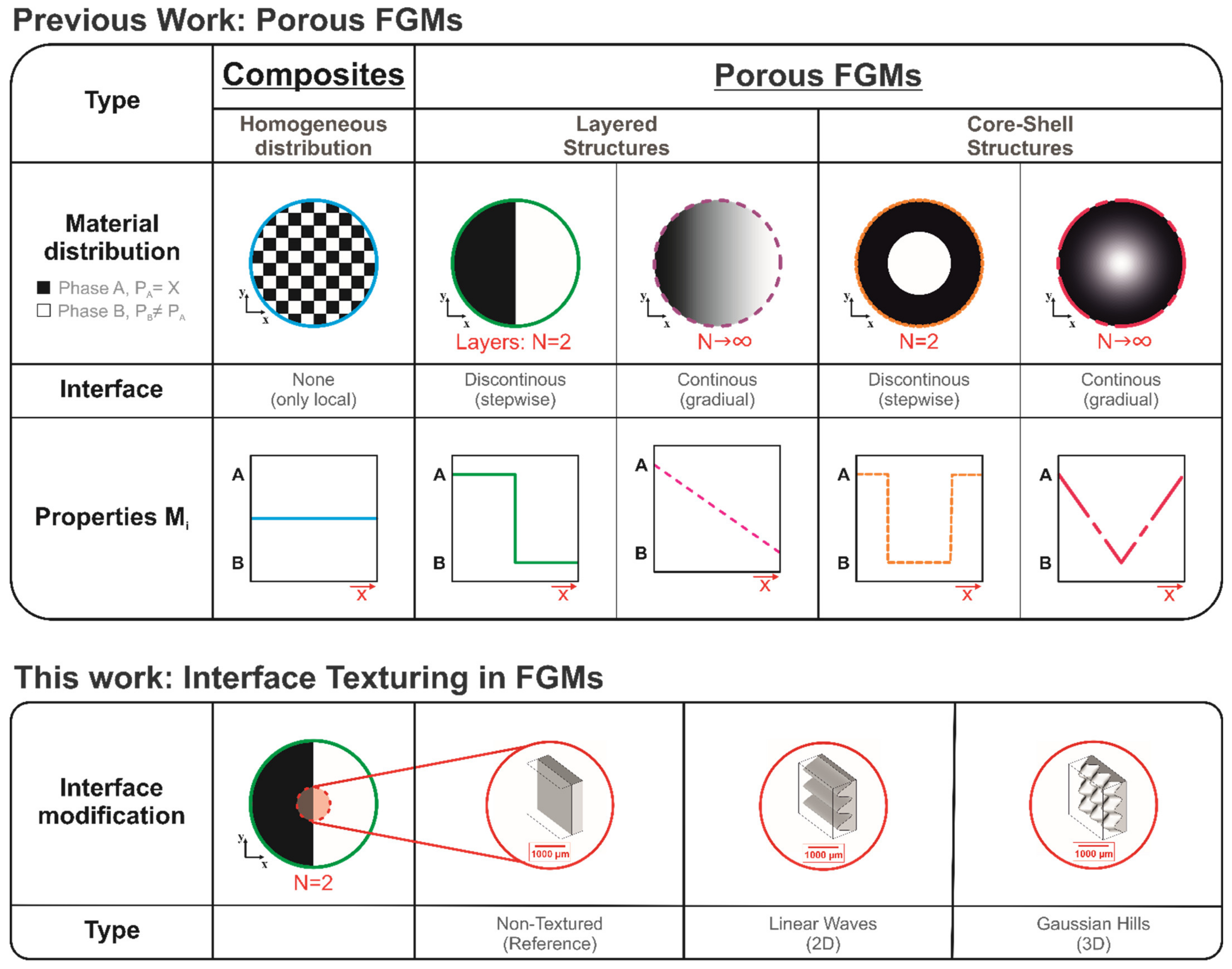
In this context, porous ceramic FGCs gained recent interest as next generation biomaterials to overcome the mechanical weaknesses of homogeneous porous ceramics by combining the advantageous of dense and porous ceramics in a single material [7,11,12,13,14]. Porous FGCs are characterized by a gradient in their density, which can be continuous (gradually [15,16,17,18]) or discontinuous (stepwise [7,19,20,21,22]) and arranged in layers [21,22]) or as core-shell structures [7,15,19,20]), as schematically shown in Figure 1. The density gradient ρi(x,y,z) induces location-dependent properties Mi(x,y,z) along the spatial directions (x,y,z) and thus perspective biomedical applications that cannot be achieved by common homogeneous porous ceramics, for which ρi and Mi are constant in volume [23,24,25]. Graded porosities were commonly achieved by modifying established fabrication techniques of homogeneous porous ceramics, including sacrificial templating [7,14,21,22,26], direct foaming [15,18,27], freeze casting [19,28], emulsion forming [29,30], replica technique [20,31,32,33] and additive manufacturing (AM) [16,17,31,32]. Among the various mentioned processing routes, techniques utilizing computer-aided designing provide the highest potential to realize freely adjustable graded architectures with complex shapes [17,31], which are required for the fabrication of patient individual implants.
While previous research on porous FGCs has so far concentrated on the generation of different graded porous architectures, we focus now on the interfaces in the porous FGCs. The tailored modification of the interface morphology is of particular interest to locally adapt the microstructural and mechanical properties. Our group has recently shown that ceramic transfer micro-molding can be used to generate hierarchical surface textured ceramics with well-defined periodic surface patterns in the submillimeter range [34]. Surface patterns with various morphologies can be computer-aided designed, 3D-printed with polymeric SLA-technology and afterwards demolded with an elastomer to obtain a negative casting mold with the embossed pattern [34]. The patterns are then transferred to the ceramic during the subsequent micro-molding, which, in comparison to AM, represents a near-net shape manufacturing of ceramics on an industrial scale [34,35]. Moreover, this identical technique can be coupled with sacrificial templating to obtain near-net shaped implants with complex geometries and a pore structure, which can deliberately be modified by changing the amount, shape and size of the utilized pore formers [36].
In this work, we modified the described technique [34,35,36] to a two-step transfer molding process to manufacture bi-layered porous FGCs with well-defined integrated interface textures consisting of alumina (Al2O3) and hydroxyapatite (HAp). Three type of interface morphologies including a planar non-textured reference, two-dimensional linear waves and three-dimensional Gaussian hills were realized (Figure 1). Various porosity pairings containing between 0 to 40 Vol% of spherical pore formers (diameter 20 µm) in each layer were realized and the resulting microstructure was investigated by SEM and µCT analysis. The Young’s modulus and flexural strength of the porous FGCs with interface textures were determined for the bi-layered dense (0 Vol%)/porous (30 Vol%) pairing and were afterwards compared to the values of homogeneous porous ceramics.
2. Materials and Methods
2.1. Fabrication of Porous Functional Graded Bioceramics with Integrated Interface Textures
Alumina (Al2O3) and hydroxyapatite (HAp) bioceramics with graded porosity and integrated interface texturing were fabricated by a two-step micro transfer-molding technique, which was combined with additional sacrificial pore formers. A detailed description of the feedstock preparation for porous injection-molded ceramics and the generation of well-defined periodic surface morphologies by micro transfer-molding can be found in [34,35,36]. Bending bars (35 mm 4 mm 3 mm) with three different texturing types were realized (Figure 2), including the planar non-textured reference (A), the two-dimensional linear waves (B) and three-dimensional Gaussian hills (C). The textures can be mathematically described by the following expressions [34], referring to the cartesian coordinate system (x,y,z) shown in Figure 2:
- (A)
- (B)
- (C)
with an identical amplitude of 250 µm ( and wavelength of 550 µm (. The textures were designed in blender (v.2.92, Stichting Blender Foundation, Amsterdam, The Netherlands). The CAD-files were 3D-printed using a stereolithographic 3D-printer (printer: Digitalwax® 028J, resin: Fusia DC700, both: DWS S.r.l., Zanè, Italy) with a z-layer resolution of 20 µm and afterwards molded with a polydimethylsiloxane elastomer (PDMS, Elastosil M4643 A/B, Wacker Chemie AG, München, Germany) to obtain negative casting molds with the embossed patterns. The initial Al2O3 feedstock contained a solid loading of 53 Vol% hydrophobized Al2O3 powder (CT3000SG, Almatis GmbH, Ludwigshafen, Germany), 42.2 Vol% paraffin wax (Granopent P, Carl Roth GmbH, Karlsruhe, Germany) and 4.8 Vol% carnauba wax (naturfarben, Carl Roth GmbH, Karlsruhe, Germany). For HAp, an initial feedstock with a solid loading of 50 Vol% of hydrophobized HAp (04238, Sigma-Aldrich Corp., St. Louis, MO, USA) and an identical paraffin wax to carnauba wax volume-ratio was used. The well-defined porosities were generated by adding varied amounts (0, 10, 20, 30 and 40 Vol%) of spherical pore formers (phenolic resin spheres, d50 = 20 µm, BRHF-035, Brace GmbH, Karlstein, Germany) to the initial feedstocks. The two-step transfer-molding was performed at 120 °C, supported by applying a gentle vacuum (<10 Pa) to ensure a contour accurate molding. Firstly, one sample half (a) with integrated interface texturing was casted (referring to Figure 2). A coalesced and shape accurate bonding between the two feedstocks was insured by joining of the green-parts in liquid-state. For that, the molded sample half (a) was placed in the bending bar mold and reheated for 3 min in the furnace at 120 °C, then the second half (b) was casted using a feedstock with different porosity. The bending bars were afterwards wick debinded in an Al2O3 nano-powder bed (d50 = 200 nm, AKP-53, Sumitomo Chemical Co. Ltd., Tokyo, Japan) and sintered at 1250 °C for 2 h for HAp and at 1600 °C for 2 h for Al2O3 respectively.
2.2. Characterization
The HAp and Al2O3 interface microstructures were investigated for the three texturing types with different porosity couplings using scanning electronic microscopy (SEM Quanta 200, FEI Deutschland GmbH, Frankfurt am Main, Germany) on two-dimensional, polished cross-sections of the yz-plane (see Figure 2E). The total porosities were determined from the geometric (bulk) density and true density, measured by Archimedes’ principle according to DIN EN 623-2 in distilled H2O [37]. The 3D-microstructure of the interfaces were characterized by micro computer tomography (µCT Skyscan 1172, Bruker Mikro CT, Kontich, Belgium) with a resolution of 2.98 µm/voxel (see Figure 2F). The tungsten X-ray tube (λ = 0.024 nm) was operated with 80 kV and 100 mA using an 11 MP detector and Al-filter. For the measurement, samples were half-rotated (180°) with step sizes of 0.2°. The reconstruction of the resulting 2D sinograms and 3D-visualization was performed with NRecon (v.1.7.3, Bruker Mikro CT, Kontich, Belgium) and Amira 3D Pro 2021.1 (Thermo Fisher Scientific Inc., Waltham, MA, USA). The Young’s moduli of the as-fired bending bars were determined by impulse excitation method according to DIN EN 843-2. The Young’s modulus was measured in out-of-plane flexure mode using a condenser microphone (Audix TM-1, Audix Microphones, Wilsonville, OR, USA) and the Buzz-o-sonic software (v.5.9, BuzzMac International LLC, Glendale, WI, USA) [38]. The flexural strengths were measured by 4-point-bending tests using a universal testing machine (Instron 5565, Instron GmbH, Pfungstadt, Germany) according to DIN EN 843-1 with a support span of 20 mm and a constant crosshead speed of 0.5 mm·min−1 [39]. The mechanical testing setup and tested sample orientations are visualized in Figure 2D and the SEM and µCT measurement setup in Figure 2E,F.
3. Results
3.1. Microstructure of Porous FGCs with Integraded Interface Textures
The control of all microstructural features (total porosity, pore size, shape, distribution and interconnectivity) in porous FGCs currently represents one of the major challenges to design tailor made implants. While some techniques, such as direct foaming [15,18,27], freeze casting [19,28] or emulsion-forming [29,30], cannot easily be adapted to meet patient individual demands without changing various process parameters, additive manufacturing (AM) allows convenient customization as required. However, as direct AM of ceramic implants remains challenging [40], established ceramic manufacturing techniques indirectly utilizing computer-aided designing provide great opportunity to fulfill the current demands [31,32]. In this work, bi-layered bending bars were fabricated by joining two ceramic feedstocks containing varied amounts of 20 µm spherical pore formers (0–40 Vol%), which generated a well-defined porosity after the heat treatment inside each layer. Sacrificial templating is the most straightforward technique to directly tailor the pore architecture by changing the pore former content, shape or size [41,42] and can be successfully coupled with ceramic transfer molding to realize complex shaped implants [36]. The interfaces of the fabricated porous Al2O3 FGCs with various porosity pairings are shown in the cross-sectional SEM micrographs of the yz-plane in Figure 3, referring to the cartesian coordinate system of Figure 2. The microstructure of the porous HAp FGCs is identical to the presented Al2O3 micrographs and thus will not be shown here.
A defect-free, substance-to-substance bonding could be achieved over the entire sample cross-section (4 mm 3 mm) for all porosity pairings, independent of the utilized pore former content in each layer, proving that dense and porous layers, as well as different porous layers, can be deliberately combined to bi-layers. The coalesced bonding was insured by joining the two green parts in a liquid state (T > 80 °C), for which the pre-casted first sample half (with integrated pattern) was reheated before casting of the second sample half with a different content of pore formers. The process parameters (temperature, time) of the second casting step are crucial and must be empirically adjusted to the sample geometry to provide a good adhesion between the layers and to avoid deformations of the pattern or the formation of cracks in the reheated first layer. Depending on the porosity differences between the two layers, either discontinuous or continuous interfaces can be generated. For porosity differences ∆p = | p(b) − p(a) | ≥ 20 Vol% the interface is characterized by a discontinuous interface, shown in the stepwise porosity transition and clear detectable interface for the left column in Figure 3. If the porosity difference is decreased to ∆p ≤ 10 Vol% the transition between the layers becomes indistinct and continuous, thus gradient interfaces can be obtained (middle column Figure 3). The amount of pore formers in each layer decides if the entire porous FGC provides an interconnected open porous network or not. Up to a volume content of 20 Vol% spherical pore formers (20 µm), the majority of the pores were isolated and thus led to a closed porosity in both Al2O3 and HAp. Interconnected pore networks were generated by the addition of 30 Vol% and higher amounts of 20 µm sized spherical pore formers. The complete control of the porosity fractions (closed & open porosity) and their distribution in the volume allows one to tailor the properties and thus offers various fields of application [43].
This technique can, moreover, be used to realize complex morphologies at the interfaces with well-defined periodicity in the submillimeter range. As shown in the SEM sections of the right column of Figure 3, a contour-accurate molding with defect-free interfaces could also be obtained for the patterns of the two-dimensional linear waves and the three-dimensional Gaussian hills. As investigations of interfaces with SEM are limited to two-dimensional cross-sections, we applied µCT analysis to obtain a three-dimensional insight in the porous FGCs to evaluate the morphologies of the integrated interface textures in the volume. The 3D-reconstructed µCT-images of porous FGCs with interface texturing are shown in Figure 4 in comparison to SEM-micrographs of the interface texturing types (A–C), which were prepared by debinding and sintering the first specimen half without performing the gradation step. The SEM-micrographs serve as an optical reference to show the ideal morphologies, that can be theoretically obtained in the porous FGC.
As shown in the µCT-images of Figure 4D–F, the well-defined periodic patterns could be successfully preserved in the porous FGCs for all texture types. Locally, slight deformations may occur, especially at sample edges, which can be attributed to applying temperatures or pressures that are too high during the second molding step.
3.2. Mechanical Properties of Porous FGCs with Integrated Interface Textures
The mechanical properties of the porous FGCs with integrated interface textures were evaluated by impulse excitation and 4-point bending to determine the Young’s modulus (E) and the flexural strength (σ) in comparison to homogeneous porous Al2O3 and HAp ceramics. For the homogeneous porous samples, the pore former content of 20 µm spheres was varied between 0 to 40 Vol%. While for the porous FGCs with interface textures, the strength and stiffness were examined for the bi-layered porosity pairing with 0 Vol% of pore formers in layer A (dense) and 30 Vol% of pore formers in layer B (porous), which will be from now on specified as 0/30 Vol%. Figure 5A shows the mechanical properties (σ, E) for both homogeneous porous and porous FGC samples in dependence of the total porosity, the corresponding values are summarized in Table 1. To facilitate the differentiation between the homogeneous and graded porous sample series, a magnified section of Figure 5A is shown in the porosity range of 14 to 31 Vol% in Figure 5B.
Young’s modulus and flexural strength showed an exponential decrease with increasing porosity for both homogeneous porous Al2O3 and HAp, Figure 5A. The semi-empirical model of Phani et al. was used to fit the experimental data of the samples with homogeneous porosity by the following power-law approach [44]:
The porous modulus Mp (here Ep, σp) can be expressed by the dense modulus M0 (here E0, σ0), the porosity Vp and the dimensionless exponent n. The exponent n was shown to vary between 2 and 7, depending on the pore shape and orientation with respect to the stress axis and equals to n = 2.0–2.3 for ideal spherical shaped pores [45,46,47]. As shown in Figure 5A and Table 1, an excellent agreement was found between the experimental data of both homogeneous porous materials and the model of Equation (1), obtaining R² ≥ 0.995 and n-values close to the ones of ideal spherical pores. Only the flexural strength of HAp showed slightly deviations, with n = 3.69 and R² = 0.982, which are in a tolerable range [36]. The fitted dense moduli (E0, σ0) are consistent with the reported literature values for both Al2O3 [48,49] and HAp [50,51], which, however, can strongly vary depending on the powder synthesis and purity, the grain size and orientation as well as the residual porosity. Thus, the model of Phani is suitable to predict the properties of the homogeneous porous materials with spherical pores in the porosity range of 0–50 Vol%.
The porous FGCs with a 0/30 Vol% porosity coupling exhibited lower Young’s moduli and flexural strengths than the homogeneous porous samples with identical porosity, which is shown in the lower values than the expected fitted confidence interval (CI) of Equation (1) (see Figure 5B). The variations in the physical properties (here Young’s modulus) of FGMs compared to homogeneous porous materials were observed by several researchers and their investigation as well as modelling are subject of current research [52,53,54]. Based on the inhomogeneous distributed porosity, FGMs are characterized by a density gradient ρi(x,y,z) generating location-dependent properties Mi(x,y,z) along the spatial directions (x,y,z) [23,24,25]. Thus, the physical properties of porous FGMs cannot be modelled by simple porosity models (such as the discussed Phani model) or rule of mixtures (ROM), which were developed for homogeneous materials by Reuss and Voigt [55,56], but require a location-dependent variable. For the unidirectional graded porous FGMs of this work, we implemented a power-law approach according to [52,54]. It describes the location-dependent porosity Vf(z) and corresponding material property MFGM(z) along the z-axis (referring to the cartesian coordinate system of Figure 2, but setting the origin to the sample middle directly at the interface):
where l corresponds to the sample length, k to the volume index and M(a) and M(b) to the material property of layer (a) and (b), which are here equivalent to the Young’s modulus of the dense (0 Vol%) and porous (30 Vol%) of Al2O3 and HAp respectively. For k = 0, the properties correspond to a homogeneous material (with properties of M(a)); for k = 1, Equation (3) is simplified to the linear ROM. As shown in Figure 5C,D, an excellent agreement was achieved by fitting the model of Equation (3) to the experimental data, obtaining nearly identical k-values for both HAp and Al2O3 (see also Table 1). The matching k-values suggest that the model is suitable to also describe the here-investigated discontinuous FGMs. The mechanism of the Young’s modulus reduction compared to the homogeneous porous samples (Phani or ROM model) is, however, not entirely clear. Since the out-of-plane flexure mode was measured, where the mechanical vibrations propagate through the interface (see Figure 2D), we assume that this effect can be attributed to the discontinuous interface influence. The transition of different porosity levels leads to a distortion of the mechanical vibrations (damping effects) resulting in a lowered Young’s modulus. To verify this assumption, future investigations with different porosity pairings, as well as dis- and continuous gradation, are mandatory. Nevertheless, solely by changing the distribution of the pores in the volume, the Young’s modulus could be reduced for the porous FGCs by ~12% for Al2O3 and ~18% for HAp compared to the homogeneous porous samples (Equation (1)). A reduction of the high Young’s modulus of ceramics is highly attractive to reduce stress shielding effects of potential implants [17,57] and might also be beneficial for Al2O3 ceramics with an improved thermal shock resistance for high temperature applications [58]. No significant difference between the three interface textures could be monitored with the used equipment, showing that the macroscopic Young’s modulus of the entire sample was not affected by varied interface morphologies on this order of magnitude.
In contrast to the reduced stiffness, the decreased flexural strength cannot be attributed to interface effects. For all porous FGC specimen series, the material failure did not originate at the interface, but occurred in the porous 30 Vol% layer between the inner support spans of the 4-point bending setup, as schematically shown in Figure 5E,F. We therefore compared the flexural strength of the porous 0/30 Vol% FGC samples to the homogeneous porous samples with 30 Vol% of pore formers in the boxplot of Figure 5C. No significant difference with respect to the standard deviations could be monitored, and all FGCs series showed the identical strength to the 30 Vol% homogeneous porous samples. This proves that the interfaces do not represent weakening points in the microstructure of the porous FGCs [33] and that, with the here demonstrated transfer-molding technique, a mechanically stable and defect-free bonding between layers with different porosities could be achieved. However, since the failure was not located at the interface, no differences for the three texturing types could be observed; thus, the full mechanical potential of the interface-textured FGCs was not exploited. To our beliefs, the modification of the interface morphologies bears tremendous potential to improve the damage tolerance and fracture toughness of porous FGCs in the presence of defects, such as cracks. Multilayered ceramics with alternated porous and dense stacking sequence were shown to exhibit significant crack deflection mechanisms, if a certain minimal porosity (approx. > 40 Vol%) inside the porous layer is provided [59,60,61]. The crack propagation in these structures predominantly occurs at the interface between the dense and porous layers [61,62]. Thus, by replacing planar interfaces by three-dimensional periodic interfaces, such as the proposed linear waves or Gaussian hills, a pronounced crack deflection with elongated crack paths can be expected and improved fracture toughness might be achieved. The crack propagation can then be controlled by modifying shape, orientation, amplitude, and wavelength of the periodic patterns.
4. Conclusions
Porous functional graded ceramics (porous FGCs) with integrated interface textures have been fabricated by a novel two-step transfer-molding technique using alumina (Al2O3) and hydroxyapatite (HAp) feedstocks with varied amounts of spherical pore formers (0–40 Vol%) to generate well-defined porosities. Defect-free, substance-to-substance bondings could be achieved for all porosity pairings independent of the utilized pore former content, demonstrating a free combinability. Depending on the porosity differences between the layers either discontinuous (∆p ≥ 20 Vol%) or continuous (∆p ≤ 10 Vol%) porosity transitions could be deliberately achieved. Discontinuous interfaces with a stepwise porosity transition are highly attractive to mimic the macroscopic architecture of natural bone, while continuous interfaces with a smooth transition of porosity may reduce stress shielding and optimize the cell ingrowth and resorption rates of potential implants. Moreover, two types of complex interface morphologies (2D-linear waves and 3D-Gaussian hills) with a well-defined periodicity in the submillimeter range could be realized in the porous FGCs. The interface patterns can be CAD-designed and thus deliberately modified, 3D-printed, demolded and, afterwards, directly transferred into the ceramic during the transfer micro-molding. µCT-analysis revealed that these patterns could be successfully preserved inside the porous FGCs with a contour- and shape-accurate replication of the 3D-printed model.
The Young’s modulus and flexural strength of the porous FGCs were exemplary investigated for the 0–30 Vol% porosity pairing for the three interface textures (planar reference, 2D-linear waves, 3D-Gaussian hills) and were compared to homogeneous porous Al2O3 and HAp ceramics containing 0–40 Vol% pore formers. A significant reduction of the Young’s modulus compared to the homogeneous porous ceramics with identical porosity was observed, which can be modelled by a location-dependent power-law approach and which is highly attractive to reduce stress shielding effects in potential implants. The flexural testing revealed that the failure did not occur at the interface, but in the porous 30 Vol% layer, proving that the interfaces are free of defects and that there is no source of weakness in the microstructure. Thus, no significant differences between the different interface morphologies could be monitored. Regardless of that fact, the tailored manipulation bears tremendous potential to improve the fracture toughness of porous FGCs by deflecting the crack propagation at the porous/dense interface.
Author Contributions
Conceptualization: J.B., T.F.; methodology: J.B., D.K. and T.F.; investigations: J.B., D.K., S.S., P.H. (Patrizia Hoffmann), P.H. (Paula Heik), and T.F.; formal analysis: J.B. and T.F.; writing—original draft preparation: J.B.; writing, review and editing: J.B., T.F.; visualization: J.B., D.K. and T.F.; supervision: T.F.; project administration: T.F.; funding acquisition: J.B., T.F. All authors have read and agreed to the published version of the manuscript.
Funding
The financial support of the German Research foundation (DFG) of the International Research and Training Group GRK 2495 and especially the personal funding of research scholarships for doctoral students of the German Academic Exchange Service (DAAD, 57504619) is gratefully acknowledged.
Institutional Review Board Statement
Not applicable.
Informed Consent Statement
Not applicable.
Acknowledgments
The authors thank the BRACE GmbH for providing the phenolic resin spheres used as sacrificial templates in this work and the Almatis GmbH for providing the utilized alumina powder.
Conflicts of Interest
The authors declare no conflict of interest.
References
- Giannoudis, P.V.; Dinopoulos, H.; Tsiridis, E. Bone substitutes: An update. Injury 2005, 36 (Suppl. 3), S20–S27. [Google Scholar] [CrossRef]
- White, A.A.; Best, S.M.; Kinloch, I.A. Hydroxyapatite? Carbon Nanotube Composites for Biomedical Applications: A Review. Int. J. Appl. Ceram. Technol. 2007, 4, 1–13. [Google Scholar] [CrossRef]
- Bohner, M.; Le Santoni, B.G.; Döbelin, N. β-tricalcium phosphate for bone substitution: Synthesis and properties. Acta Biomater. 2020, 113, 23–41. [Google Scholar] [CrossRef]
- Bohner, M.; Baumgart, F. Theoretical model to determine the effects of geometrical factors on the resorption of calcium phosphate bone substitutes. Biomaterials 2004, 25, 3569–3582. [Google Scholar] [CrossRef] [PubMed]
- Deville, S.; Saiz, E.; Tomsia, A.P. Freeze casting of hydroxyapatite scaffolds for bone tissue engineering. Biomaterials 2006, 27, 5480–5489. [Google Scholar] [CrossRef] [PubMed] [Green Version]
- Liu, D.-M. Influence of porosity and pore size on the compressive strength of porous hydroxyapatite ceramic. Ceram. Int. 1997, 23, 135–139. [Google Scholar] [CrossRef]
- Zhang, F.; Chang, J.; Lu, J.; Lin, K.; Ning, C. Bioinspired structure of bioceramics for bone regeneration in load-bearing sites. Acta Biomater. 2007, 3, 896–904. [Google Scholar] [CrossRef] [PubMed]
- Andersson, L.; Jones, A.C.; Knackstedt, M.A.; Bergström, L. Permeability, pore connectivity and critical pore throat control of expandable polymeric sphere templated macroporous alumina. Acta Mater. 2011, 59, 1239–1248. [Google Scholar] [CrossRef]
- Petit, C.; Meille, S.; Maire, E.; Tadier, S.; Adrien, J. Mechanical behaviour of a β-TCP ceramic with a random porosity: Study of the fracture path with X-ray tomography. J. Eur. Ceram. Soc. 2016, 36, 3225–3233. [Google Scholar] [CrossRef]
- Ahn, M.-K.; Moon, Y.-W.; Maeng, W.-Y.; Koh, Y.-H.; Kim, H.-E. Calcium phosphate ceramics with continuously gradient macrochannels using three-dimensional extrusion of bilayered ceramic-camphene mixture/pure camphene feedrod. Ceram. Int. 2016, 42, 15603–15609. [Google Scholar] [CrossRef]
- Castillo, M.; Moore, J.J.; Schowengerdt, F.D.; Ayers, R.A.; Zhang, X.; Umakoshi, M.; Yi, H.C.; Guigne, J.Y. Effects of gravity on combustion synthesis of functionally graded biomaterials. Adv. Space Res. 2003, 32, 265–270. [Google Scholar] [CrossRef]
- Tampieri, A. Porosity-graded hydroxyapatite ceramics to replace natural bone. Biomaterials 2001, 22, 1365–1370. [Google Scholar] [CrossRef]
- Pompe, W.; Worch, H.; Epple, M.; Friess, W.; Gelinsky, M.; Greil, P.; Hempel, U.; Scharnweber, D.; Schulte, K. Functionally graded materials for biomedical applications. Mater. Sci. Eng. A 2003, 362, 40–60. [Google Scholar] [CrossRef]
- Maca, K.; Dobsak, P.; Boccaccini, A. Fabrication of graded porous ceramics using alumina–carbon powder mixtures. Ceram. Int. 2001, 27, 577–584. [Google Scholar] [CrossRef]
- Ceron-Nicolat, B.; Wolff, F.; Dakkouri-Baldauf, A.; Fey, T.; Münstedt, H.; Greil, P. Graded Cellular Ceramics from Continuous Foam Extrusion. Adv. Eng. Mater. 2012, 14, 1097–1103. [Google Scholar] [CrossRef]
- Sobhani, S.; Allan, S.; Muhunthan, P.; Boigne, E.; Ihme, M. Additive Manufacturing of Tailored Macroporous Ceramic Structures for High-Temperature Applications. Adv. Eng. Mater. 2020, 22, 2000158. [Google Scholar] [CrossRef]
- Vijayavenkataraman, S.; Kuan, L.Y.; Lu, W.F. 3D-printed ceramic triply periodic minimal surface structures for design of functionally graded bone implants. Mater. Des. 2020, 191, 108602. [Google Scholar] [CrossRef]
- Zeschky, J.; Höfner, T.; Arnold, C.; Weißmann, R.; Bahloul-Hourlier, D.; Scheffler, M.; Greil, P. Polysilsesquioxane derived ceramic foams with gradient porosity. Acta Mater. 2005, 53, 927–937. [Google Scholar] [CrossRef]
- Lee, H.; Jang, T.-S.; Song, J.; Kim, H.-E.; Jung, H.-D. The Production of Porous Hydroxyapatite Scaffolds with Graded Porosity by Sequential Freeze-Casting. Materials 2017, 10, 367. [Google Scholar] [CrossRef]
- Lindner, M.; Bergmann, C.; Telle, R.; Fischer, H. Calcium phosphate scaffolds mimicking the gradient architecture of native long bones. J. Biomed. Mater. Res. A 2014, 102, 3677–3684. [Google Scholar] [CrossRef] [PubMed]
- Wang, Q.; Wang, Q.; Wan, C. Preparation and evaluation of a biomimetic scaffold with porosity gradients in vitro. An. Acad. Bras. Cienc. 2012, 84, 9–16. [Google Scholar] [CrossRef] [PubMed]
- Werner, J.; Linner-Krčmar, B.; Friess, W.; Greil, P. Mechanical properties and in vitro cell compatibility of hydroxyapatite ceramics with graded pore structure. Biomaterials 2002, 23, 4285–4294. [Google Scholar] [CrossRef]
- Kieback, B.; Neubrand, A.; Riedel, H. Processing techniques for functionally graded materials. Mater. Sci. Eng. A 2003, 362, 81–106. [Google Scholar] [CrossRef]
- Miao, X.; Sun, D. Graded/Gradient Porous Biomaterials. Materials 2010, 3, 26–47. [Google Scholar] [CrossRef] [Green Version]
- Petit, C.; Montanaro, L.; Palmero, P. Functionally graded ceramics for biomedical application: Concept, manufacturing, and properties. Int. J. Appl. Ceram. Technol. 2018, 15, 820–840. [Google Scholar] [CrossRef]
- Topateş, G. Al2O3 Ceramics with Graded Porosity Produced from Natural and Artificial Pore Formers. Politek. Derg. 2017, 22, 595–598. [Google Scholar] [CrossRef]
- Xu, C.; Liu, H.; Yang, H.; Yang, L. A Green Biocompatible Fabrication of Highly Porous Functional Ceramics with High Strength and Controllable Pore Structures. J. Mater. Sci. Technol. 2016, 32, 729–732. [Google Scholar] [CrossRef]
- Hong, C.; Du, J.; Liang, J.; Zhang, X.; Han, J. Functionally graded porous ceramics with dense surface layer produced by freeze-casting. Ceram. Int. 2011, 37, 3717–3722. [Google Scholar] [CrossRef]
- Garcia-Tunon, E.; Barg, S.; Bell, R.; Weaver, J.V.M.; Walter, C.; Goyos, L.; Saiz, E. Designing smart particles for the assembly of complex macroscopic structures. Angew. Chem. Int. Ed. Engl. 2013, 52, 7805–7808. [Google Scholar] [CrossRef] [PubMed]
- García-Tuñón, E.; Machado, G.C.; Schneider, M.; Barg, S.; Bell, R.V.; Saiz, E. Complex ceramic architectures by directed assembly of ‘responsive’ particles. J. Eur. Ceram. Soc. 2017, 37, 199–211. [Google Scholar] [CrossRef]
- Scheithauer, U.; Kerber, F.; Füssel, A.; Holtzhausen, S.; Beckert, W.; Schwarzer, E.; Weingarten, S.; Michaelis, A. Alternative Process Routes to Manufacture Porous Ceramics-Opportunities and Challenges. Materials 2019, 12, 663. [Google Scholar] [CrossRef] [PubMed] [Green Version]
- Capasso, I.; Liguori, B.; Verdolotti, L.; Caputo, D.; Lavorgna, M.; Tervoort, E. Process strategy to fabricate a hierarchical porosity gradient in diatomite-based foams by 3D printing. Sci. Rep. 2020, 10, 612. [Google Scholar] [CrossRef]
- Hsu, Y.H.; Turner, I.G.; Miles, A.W. Fabrication of porous bioceramics with porosity gradients similar to the bimodal structure of cortical and cancellous bone. J. Mater. Sci. Mater. Med. 2007, 18, 2251–2256. [Google Scholar] [CrossRef] [PubMed]
- Biggemann, J.; Müller, P.; Köllner, D.; Simon, S.; Hoffmann, P.; Heik, P.; Lee, J.H.; Fey, T. Hierarchical Surface Texturing of Hydroxyapatite Ceramics: Influence on the Adhesive Bonding Strength of Polymeric Polycaprolactone. J. Funct. Biomater. 2020, 11, 73. [Google Scholar] [CrossRef]
- Biggemann, J.; Diepold, B.; Pezoldt, M.; Stumpf, M.; Greil, P.; Fey, T. Automated 3D assembly of periodic alumina-epoxy composite structures. J. Am. Ceram. Soc. 2018, 101, 3864–3873. [Google Scholar] [CrossRef]
- Biggemann, J.; Hoffmann, P.; Hristov, I.; Simon, S.; Müller, P.; Fey, T. Injection Molding of 3-3 Hydroxyapatite Composites. Materials 2020, 13, 1907. [Google Scholar] [CrossRef] [Green Version]
- European Commitee of Standardization. Advanced Technical Ceramics; Monolithic Ceramics; General and Textural Properties; Part 2: Determination of Density and Porosity; German Version DIN EN 623-2:1993-11; Beuth Verlag GmbH: Berlin, Germany, 1993. [Google Scholar]
- European Commitee of Standardization. Advanced Technical Ceramics—Mechanical Properties of Monolithic Ceramics at Room Temperature—Part 2: Determination of Young’s Modulus, Shear Modulus and Poisson’s Ratio; German Version EN 843-2:2006; Beuth Verlag GmbH: Berlin, Germany, 2006. [Google Scholar]
- European Commitee of Standardization. Advanced Technical Ceramics—Mechanical Properties of Monolithic Ceramics at Room Temperature—Part 1: Determination of Flexural Strength; German Version EN 843-1:2006; Beuth Verlag GmbH: Berlin, Germany, 2006. [Google Scholar]
- Zocca, A.; Colombo, P.; Gomes, C.M.; Günster, J. Additive Manufacturing of Ceramics: Issues, Potentialities, and Opportunities. J. Am. Ceram. Soc. 2015, 98, 1983–2001. [Google Scholar] [CrossRef]
- Ohji, T.; Fukushima, M. Macro-porous ceramics: Processing and properties. Int. Mater. Rev. 2012, 57, 115–131. [Google Scholar] [CrossRef]
- Studart, A.R.; Gonzenbach, U.T.; Tervoort, E.; Gauckler, L.J. Processing Routes to Macroporous Ceramics: A Review. J. Am. Ceram. Soc. 2006, 89, 1771–1789. [Google Scholar] [CrossRef]
- Vakifahmetoglu, C.; Semerci, T.; Soraru, G.D. Closed porosity ceramics and glasses. J. Am. Ceram. Soc. 2020, 103, 2941–2969. [Google Scholar] [CrossRef]
- Phani, K.K.; Niyogi, S.K. Young’s modulus of porous brittle solids. J. Mater. Sci. 1987, 22, 257–263. [Google Scholar] [CrossRef]
- Andersson, C.A. Derivation of the Exponential Relation for the Effect of Ellipsoidal Porosity on Elastic Modulus. J. Am. Ceram. Soc. 1996, 79, 2181–2184. [Google Scholar] [CrossRef]
- Pabst, W.; Gregorová, E. Young’s modulus of isotropic porous materials with spheroidal pores. J. Eur. Ceram. Soc. 2014, 34, 3195–3207. [Google Scholar] [CrossRef]
- Travitzky, N.; Windsheimer, H.; Fey, T.; Greil, P. Preceramic Paper-Derived Ceramics. J. Am. Ceram. Soc. 2008, 91, 3477–3492. [Google Scholar] [CrossRef]
- Louet, N.; Gonon, M.; Fantozzi, G. Influence of the amount of Na2O and SiO2 on the sintering behavior and on the microstructural evolution of a Bayer alumina powder. Ceram. Int. 2005, 31, 981–987. [Google Scholar] [CrossRef]
- Barros, M.D.; Rachadel, P.L.; Fredel, M.C.; Janssen, R.; Hotza, D. Mechanical Behaviour of Zirconia-Toughened Alumina Laminates with or without Y-PSZ Intermediate Layers. J. Ceram. Sci. Technol. 2017, 9, 69–78. [Google Scholar] [CrossRef]
- Akao, M.; Aoki, H.; Kato, K. Mechanical properties of sintered hydroxyapatite for prosthetic applications. J. Mater. Sci. 1981, 16, 809–812. [Google Scholar] [CrossRef]
- Orlovskii, V.P.; Komlev, V.S.; Barinov, S.M. Hydroxyapatite and Hydroxyapatite-Based Ceramics. Inorg. Mater. 2002, 38, 973–984. [Google Scholar] [CrossRef]
- Zaidi, M.; Joshi, K.K.; Shukla, A.; Cherinet, B. (Eds.) A review of the various modelling schemes of unidirectional functionally graded material structures; AIP Publishing: Jamshedpur, India, 2021. [Google Scholar]
- Daikh, A.A.; Zenkour, A.M. Effect of porosity on the bending analysis of various functionally graded sandwich plates. Mater. Res. Express 2019, 6, 65703. [Google Scholar] [CrossRef]
- Mota, A.F.; Loja, M.A.R. Mechanical Behavior of Porous Functionally Graded Nanocomposite Materials. C 2019, 5, 34. [Google Scholar] [CrossRef] [Green Version]
- Reuss, A. Berechnung der Fließgrenze von Mischkristallen auf Grund der Plastizitätsbedingung für Einkristalle. Z. Angew. Math. Mech. 1929, 9, 49–58. [Google Scholar] [CrossRef]
- Voigt, W. Ueber die Beziehung zwischen den beiden Elasticitätsconstanten isotroper Körper. Ann. Phys. 1889, 274, 573–587. [Google Scholar] [CrossRef] [Green Version]
- Ridzwan, M.; Shuib, S.; Hassan, A.Y.; Shokri, A.A.; Ibrahim, M.N. Problem of Stress Shielding and Improvement to the Hip Implant Designs: A Review. J. Med Sci. 2007, 7, 460–467. [Google Scholar] [CrossRef] [Green Version]
- Greil, P. Advanced Engineering Ceramics. Adv. Mater. 2002, 14, 709. [Google Scholar] [CrossRef]
- Leguillon, D.; Tariolle, S.; Martin, E.; Chartier, T.; Besson, J.L. Prediction of crack deflection in porous/dense ceramic laminates. J. Eur. Ceram. Soc. 2006, 26, 343–349. [Google Scholar] [CrossRef]
- Reynaud, C.; Thévenot, F.; Chartier, T.; Besson, J.-L. Mechanical properties and mechanical behaviour of SiC dense-porous laminates. J. Eur. Ceram. Soc. 2005, 25, 589–597. [Google Scholar] [CrossRef]
- Davis, J.B.; Kristoffersson, A.; Carlström, E.; Clegg, W.J. Fabrication and Crack Deflection in Ceramic Laminates with Porous Interlayers. J. Am. Ceram. Soc. 2000, 83, 2369–2374. [Google Scholar] [CrossRef]
- Sørensen, B.F.; Horsewell, A. Crack Growth along Interfaces in Porous Ceramic Layers. J. Am. Ceram. Soc. 2001, 84, 2051–2059. [Google Scholar] [CrossRef]
Figure 1.
Fabrication of functional graded porous ceramics (porous FGCs) with integrated interface textures to tune the interface properties of porous FGCs. Based on their density gradient ρi(x,y,z), porous FGCs exhibit location-dependent properties Mi(x,y,z), which cannot be achieved by conventional ceramics with homogeneous porosity (Mi = const.). In this work, porous FGCs with three well-defined interface morphologies (non-textured reference, linear waves and Gaussian hills) in the submillimeter range were realized.

Figure 2.
Schematic representation of the fabricated bending bars (35 mm 4 mm 3 mm) with graded porosity and integrated interface textures including the planar non-textured reference (A), two-dimensional linear waves (B) and three-dimensional Gaussian Hills (C). The individually colored sample halves (a) and (b) represent layers with different amounts of pore formers and thus with different porosity. (D) shows the utilized testing setups and sample orientation for the mechanical characterization by impulse excitation and 4-point-bending. (E,F) show schematically the performed two- and three-dimensional microstructural analysis by SEM and µCT measurements.

Figure 3.
Microstructure of the porous functional graded Al2O3 ceramics (porous FGCs) with integrated interface-textures. The two-dimensional SEM cross-sections of the yz-plane show the interfaces (marked by the orange arrows and shown with larger magnification in the orange boxes) for various porosity pairings. The numbers above each image represent the amount of pore formers in each layer, the grey color of the SEM-micrographs corresponds to the ceramic matrix and the black color to the spherical pores. For porosity differences ∆p > 20 Vol% the gradient is discontinuous (left column), while for small porosity differences ∆p < 10 Vol% continuous gradients (middle column) can be obtained. The right column shows the three realized interface textures: planar non-textured reference (A), two-dimensional linear waves (B) and three-dimensional Gaussian hills (C).

Figure 4.
The SEM-micrographs (A–C) show the microstructure and ideal realizable morphologies of the individual interface texturings (non-textured, planar reference (A); 2D-linear waves (B); 3D-Gaussian hills (C) serving as an optical reference to the reconstructed µCT-images (C–F). The µCT-images visualize the real 3D-microstructure and morphology of the interface texturings for a porosity pairing with 0 and 30 Vol% of pore formers. To highlight the morphological differences between the three texture types, each interface was colored using semi-transparent lines.

Figure 5.
Mechanical properties of the porous functional graded and homogeneous porous Al2O3 (black) and HAp (red) ceramics: (A) shows the Young’s modulus and flexural strength in dependence of the total porosity. The model of Phani (Equation (1), black dashed curve with greyish colored 95% confidence interval) was used to fit the experimental data of the homogeneous porous samples (unfilled symbols). The porous FGCs with a porosity coupling of 0/30 Vol% of pore formers are highlighted by the filled symbols. (B) shows a magnified section of (A) in a porosity range of 14 to 31 Vol%, to highlight the differences between homogeneous and graded porous samples. In (C,D), the location-dependent Young’s modulus is plotted along the z-axis (referring to the cartesian coordinate system of Figure 2, but setting the origin to the sample middle directly at the interface): The Young’s modulus of the FGCs can be estimated by fitting the power-law approach of Equation (3). The boxplot of (E) shows the flexural strengths and (F) the corresponding schematic failure behavior of the different interface texturing types (structures A,B,C) of the porous FGCs compared to the homogeneous porous sample series (reference R) with 30 Vol% of pore formers. The values of the homogeneous porous HAp were taken from our previous publication [36], all other presented data are from this work.


Table 1.
Physical properties of the porous functional graded HAp and Al2O3 ceramics with a 0–30 Vol% porosity pairing compared to the homogeneous porous HAp and Al2O3 ceramics containing 0–40 Vol% of 20 µm spherical pore formers.
Table 1.
Physical properties of the porous functional graded HAp and Al2O3 ceramics with a 0–30 Vol% porosity pairing compared to the homogeneous porous HAp and Al2O3 ceramics containing 0–40 Vol% of 20 µm spherical pore formers.
| Hydroxyapatite (HAp) | |||
| Homogeneous Porous Ceramics (from Ref. [36]) | |||
| Pore former Content/Vol% | Porosity (Φp)/Vol% | Young’s Modulus (E)/GPa | Flexural strength (σf)/MPa |
| 0 | 11.2 ± 1.0 | 97.3 ± 1.9 | 69.0 ± 10.9 |
| 10 | 16.3 ± 1.3 | 83.1 ± 3.9 | 51.1 ± 12.5 |
| 20 | 28.8 ± 1.7 | 57.0 ± 2.5 | 31.4 ± 5.6 |
| 30 | 36.8 ± 1.4 | 42.8 ± 3.1 | 18.1 ± 2.3 |
| 40 | 45.2 ± 0.9 | 29.1 ± 0.9 | 13.0 ± 3.0 |
| Phani model: | E0 = 131, b = 2.49 (R² = 0.999) | σ0 = 104, b = 3.69 (R² = 0.982) | |
| Porous Functional Graded Ceramics (porous FGCs, this work) | |||
| Porosity pairing/Texture Type | Porosity (Φp)/Vol% | Young’s Modulus (E)/GPa | Flexural strength (σf)/MPa |
| 0–30/Planar (A) | 23.3 ± 1.0 | 57.2 ± 3.0 | 17.9 ± 4.2 |
| 0–30/Waves (B) | 22.7 ± 1.3 | 58.7 ± 2.8 | 16.5 ± 1.8 |
| 0–30/Hills (C) | 22.7 ± 1.5 | 57.6 ± 3.9 | 17.5 ± 3.5 |
| Power-law (Equation (3)) | k = 0.47 (R² = 0.999) | ||
| Alumina (Al2O3) | |||
| Homogeneous Porous Ceramics (this work) | |||
| Pore former content/Vol% | Porosity (Φp)/Vol% | Young’s Modulus (E)/GPa | Flexural strength (σf)/MPa |
| 0 | 7.7 ± 1.3 | 357.3 ± 15.7 | 221.9 ± 45.1 |
| 10 | 18.6 ± 1.3 | 254.4 ± 10.8 | 155.5 ± 27.8 |
| 20 | 28.6 ± 0.9 | 187.1 ± 3.6 | 122.3 ± 25.8 |
| 30 | 37.7 ± 0.9 | 136.0 ± 9.6 | 86.5 ± 14.1 |
| 40 | 48.2 ± 1.1 | 93.0 ± 4.8 | 58.8 ± 11.1 |
| Phani model: | E0 = 415, b = 2.34 (R² = 0.995) | σ0 = 256, b = 2.27 (R² = 0.995) | |
| Porous Functional Graded Ceramics (Porous FGCs, this work) | |||
| Porosity Pairing /Texture Type | Porosity (Φp)/Vol% | Young’s Modulus (E)/GPa | Flexural Strength (σf)/MPa |
| 0–30/Planar (A) | 24.3 ± 2.3 | 196.2 ± 12.7 | 84.9 ± 20.7 |
| 0–30/Waves (B) | 23.8 ± 1.8 | 197.2 ± 8.9 | 80.3 ± 15.7 |
| 0–30/Hills (C) | 23.4 ± 0.9 | 193.4 ± 5.8 | 82.4 ± 25.2 |
| Power-law (Equation (3)) | k = 0.45 (R² = 0.999) | ||
Publisher’s Note: MDPI stays neutral with regard to jurisdictional claims in published maps and institutional affiliations. |
© 2021 by the authors. Licensee MDPI, Basel, Switzerland. This article is an open access article distributed under the terms and conditions of the Creative Commons Attribution (CC BY) license (https://creativecommons.org/licenses/by/4.0/).
Share and Cite
MDPI and ACS Style
Biggemann, J.; Köllner, D.; Simon, S.; Heik, P.; Hoffmann, P.; Fey, T. Porous Functional Graded Bioceramics with Integrated Interface Textures. Ceramics 2021, 4, 681-695. https://0-doi-org.brum.beds.ac.uk/10.3390/ceramics4040048
AMA Style
Biggemann J, Köllner D, Simon S, Heik P, Hoffmann P, Fey T. Porous Functional Graded Bioceramics with Integrated Interface Textures. Ceramics. 2021; 4(4):681-695. https://0-doi-org.brum.beds.ac.uk/10.3390/ceramics4040048
Chicago/Turabian StyleBiggemann, Jonas, David Köllner, Swantje Simon, Paula Heik, Patrizia Hoffmann, and Tobias Fey. 2021. "Porous Functional Graded Bioceramics with Integrated Interface Textures" Ceramics 4, no. 4: 681-695. https://0-doi-org.brum.beds.ac.uk/10.3390/ceramics4040048