
Optimal Conditions for the Generation of Runaway Electrons in High-Pressure Gases

1
Faculty of Physics, Tomsk State University, 36 Lenin Ave., 634050 Tomsk, Russia
2
Department of Quantum Electronics and Photonics, Tomsk State University, 36 Lenin Ave., 634050 Tomsk, Russia
*
Author to whom correspondence should be addressed.
Plasma 2024, 7(1), 201-232; https://0-doi-org.brum.beds.ac.uk/10.3390/plasma7010013
Submission received: 1 December 2023
/
Revised: 29 December 2023
/
Accepted: 3 January 2024
/
Published: 15 March 2024
(This article belongs to the Special Issue Latest Review Papers in Plasma Science 2023)
Abstract
:Runaway electron (RAE) generation in high-pressure gases is an important physical phenomenon that significantly influences discharge shapes and properties of initiated plasma. The diffuse discharges formed due to RAEs in the air and other gases at atmospheric pressure find wide applications. In the present review, theoretical and experimental results that explain the reason for RAE occurrence at high pressures are analyzed, and recommendations are given for the implementation of conditions under which the runaway electron beam (RAEB) with the highest current can be obtained at atmospheric pressure. The experimental results were obtained using subnanosecond, nanosecond, and submicrosecond generators, including those specially developed for runaway electron generation. The RAEBs were recorded using oscilloscopes and collectors with picosecond time resolution. To theoretically describe the phenomenon of continuous electron acceleration, the method of physical kinetics was used based on the Boltzmann kinetic equation that takes into account the minimum but sufficient number of elementary processes, including shock gas ionization and elastic electron scattering. The results of modeling allowed the main factors to be established that control the RAE appearance, the most important of which is electron scattering on neutral atoms and/or molecules. Theoretical modeling has allowed the influence of various parameters (including the voltage, pressure, gas type, and geometrical characteristics of the discharge gap) to be taken into account. The results of the research presented here allow RAE accelerators with desirable parameters to be developed and the possibility of obtaining diffuse discharges to be accessed under various conditions. The review consists of the Introduction, five sections, the Conclusion, and the References.
1. Introduction
The possibility of increasing the electron energy of atmospheric discharges to large values was first predicted by C.T.R. Wilson [1] at the beginning of the last century. To substantiate his idea, Wilson used J.J. Thomson’s formula [2], according to which the electron energy losses decrease in collisions with particles when the electron velocity increases. Detailed theoretical studies of runaway conditions for electrons and ions in a fully ionized plasma were carried out by R.G. Giovanelli [3] and H. Dreicer [4,5]. Thus, Dreicer suggested the terms runaway electrons (RAEs) and ions, which have become very popular nowadays.
The theory of runaway electrons in gases was further developed by A.V. Gurevich [6,7], who focused on running electrons initiated by high-energy cosmic ray particles in a weak electric field and the possibility of runaway electron breakdown [7]. G.A. Askarjan’s works [8,9] should also be mentioned as they are important for understanding electron acceleration in gas discharges to energies exceeding those at voltages applied to the interelectrode gap. In these publications, it was shown theoretically that a part of the runaway electrons could be additionally accelerated in the amplified electric field of the propagating ionization wavefront formed by low-energy plasma electrons.
The runaway electrons in the gas discharge at atmospheric pressure, in this case in helium, were first indirectly registered from bremsstrahlung X-ray radiation by S. Frankel et al. [10]. Only 40 years after the publication of C.T.R. Wilson’s first idea [1], when testing a new spark camera in work [10], was it revealed that tracks of high-energy particles could not be detected because of breakdowns initiated along the straight lines perpendicular to flat electrodes. Spark breakdowns short-circuited several successive gaps and did not provide information on a particle track. S. Frankel et al. [10] assumed that this is due to runaway electron generation when breakdowns are initiated in the first and subsequent gaps between the spark chamber plates, and the next gap is pre-ionized by X-ray bremsstrahlung radiation. To study this phenomenon, the chamber with the cathode of a small curvature radius (an important improvement for the implementation of conditions for RAE generation) and the flat anode were created. With this chamber filled with helium at atmospheric pressure, the authors managed to register the X-ray film blackening behind the thin-foil anode during the pulse discharge looking like a spark and to register luminophore glow with a PMT. The application of a tip cathode facilitated the transition to the RAE generation mode in high electric fields at atmospheric pressure and comparatively low high-voltage pulse amplitudes in the gap.
X-ray radiation in the air at atmospheric pressure was registered in the next year by Stankevich and Kalinin [11], who increased the voltage pulse amplitude up to ≈50 kV and decreased the pulse front duration down to ≈2 ns. Similar to work [10], the discharge observed in the gap was a spark. The peculiarity of work [11] was the strong blackening of the X-ray film when using the high-voltage tungsten anode. This can be explained by the use of the cathode with a sharp edge from which the discharge was initiated, and the runaway electrons were generated. Electrons were decelerated by the flat tungsten anode, thereby leading to an increase in the X-ray bremsstrahlung radiation intensity for positive polarity of the high-voltage electrode.
The next breakthrough in the study of X-ray radiation under the influence of the RAEs for various discharge forms in a non-uniform electric field with cathodes having small curvature radii was the generation of diffuse discharges in helium [12] and air [13] at atmospheric pressure. In these works, it was established that the diffuse discharge is formed by the runaway electrons in the presence of X-ray radiation.
Only in 1974, in the Russian Scientific and Research Institute of Experimental Physics (RSRIEP), was the runaway electron beam (RAEB) registered behind the anode foil during direct measurements with the help of a shunt [14]. A total of 8 × 10⁸ electrons per pulse were obtained in air at atmospheric pressure. Because of the insufficient resolution of sensors and oscilloscope, it was impossible to determine the actual RAEB pulse duration. The results on RAEB registration obtained by this scientific group were not repeated by other scientific groups, institutes, or countries for a long time (for about 30 years); see review [15] and monograph [16] that summarize the results of RAEB and X-ray radiation investigations up to 2003.
Works on the registration of X-ray radiation generation by discharges in high-pressure gases were more successful. X-ray radiation was obtained by several scientific groups from different countries; see [17,18,19,20,21,22,23] and the references in these works, including using large facilities [23]. It was shown that X-ray radiation is registered during corona discharge [18]. We do not analyze these studies in our review as the volume of the experimental and theoretical data available in the literature requires a separate review. X-ray radiation in gas discharges is generated under the influence of runaway electrons, but due to its higher penetrating ability, X-ray quanta are much easier to register. Therefore, the registration of X-ray radiation in such discharges carries, although indirect, important quantitative information about the number and energy spectrum of runaway electrons.
Note that in many first theoretical and experimental works (listed below) devoted to the study of the runaway electrons in completely ionized plasma and different gases, there were no references to pioneer C.T.R. Wilson’s works [1,24]. Apparently, these works were unknown to the majority of scientists engaged in nanosecond discharges until the 2000s. That is partly why about 50 years passed after the first idea on the possibility of generating runaway electrons in high-pressure gases was put forward in work [1] to the direct RAE registration in the air at atmospheric pressure using a shunt [14]. Moreover, the number of runaway electrons (≈8 × 10⁸) registered in the air at atmospheric pressure behind the anode foil did not increase for the next 30 years; see monograph [16]. This can be explained by the complexity of physical processes during RAE generation in gas diodes and the large diameter (30 cm) of the transmission line of the high-voltage pulse generator in the first works (see Figure 5.1.1 of work [16]) and hence, long (>1 ns) voltage pulse front duration as well as by non-optimal designs of the cathode and gas diode.
Only since 2003 has the number of scientific groups studying RAEB generation experimentally under high pressures started to increase. A large series of investigations was carried out at the High Current Electronics Institute of the Siberian Branch of the Russian Academy of Sciences (HCEI), in which the possibility of a significant increase in the number of RAEs was particularly shown. The first works were submitted for printing in December 2002 [25,26], and cycles of investigations were generalized in reviews [27,28,29,30,31] and monographs [32] written in collaboration with colleagues from other Institutes [27,29,30]. Since 2005, research has been conducted at the Institute of Electrophysics (IEP) of the Ural Branch of the Russian Academy of Sciences [33,34]; they were preceded by works [35,36,37] performed at the HCEI in collaboration with the IEP. At present, the research team from the IEP continues to conduct experimental and theoretical investigations of the RAEs in collaboration with researchers from the P.N. Lebedev Physical Institute of the Russian Academy of Sciences (LPI) [38,39,40]. The fourth scientific group [41,42] that started to investigate the RAE in collaboration with the HCEI [43,44,45,46,47] is the T. Shao research group from the Institute of Electrical Engineering (IEE) of the Chinese Academy of Sciences.
As follows from the above analysis, by the present time, the experimental investigations of RAEs at atmospheric pressure and their direct measurements using shunts and collectors have only been carried out by four scientific groups. These are the above-mentioned groups at the HCEI, IEP, LPI, and IEE. Also, the experimental and theoretical works are continued in RSRIEP [48,49,50,51]. Moreover, as reported in work [52], the researchers failed to increase the beam current amplitude to ≈8 × 10⁸ reported in work [14] even when using a modernized system equipped with an output insulator diameter of 10 cm.
The complexity of measuring the parameters of runaway electron beams, primarily their duration, amplitude, and electron energy distribution, should be pointed out, which has led to different results being obtained by various scientific groups. This is discussed in Section 5, where the results of experimental measurements of the RAEB parameters are given.
Modeling of RAE generation conditions started from the publication of the first experimental work. Thus, L.P. Babich and I.M. Kutsyk [50] developed a one-dimensional numerical model of high-voltage pulsed discharge in helium at atmospheric pressure. In monograph [53] (see p. 72), the values of the critical field in nitrogen (590 V/(cm·Torr)) and helium (150 V/(cm·Torr)) were obtained at which the first runaway electrons arise. Nowadays, these values are used as criteria in many works. In addition, on p. 77 of the same monograph and in A.V. Kozyrev et al.’s work [54], the critical fields for electrons running away were newly calculated, taking into account the effect of ionization-induced electron multiplication. These fields turned out to be about 10 times higher in nitrogen (4000 V/(cm·Torr)) and in helium (550 V/(cm·Torr)).
The need to take into account the ionization-induced multiplication of fast electrons to derive the electron runaway criterion was studied in detail in works [55,56], in which the nonlocal electron runaway criterion was used. In addition, in work [57], it was shown that the Townsend electron ionization mechanism remains valid in high fields. The results of modeling the conditions for RAE generation, obtained by the Yakovlenko research group from the Institute of General Physics of the Russian Academy of Sciences, are also presented in the articles cited in the review [27].
The model based on the program MAGIC describing the runaway electrons in helium at atmospheric pressure was developed by W. Jiang and K. Yatsui [58]. As a result of modeling, it was shown that with a tubular cathode, the beam current can reach ~1 kA at a voltage of 200 kV. The theoretical models [59,60,61,62,63,64,65,66,67,68,69,70] developed recently involve more and more factors that affect runaway electron behavior. However, even now, the RAEB generation conditions are only modeled for simplified models. The object of this research is very complex and requires various simplifying assumptions, for example when calculating emission from the cathode with a small curvature radius, the surface of which changes for each pulse at high RAE currents due to the formation of cathode spots. This process is taken into account together with some others by using various approximations.
Thus, the runaway electrons and X-rays generated by them have been and are being investigated in a large number of experimental and theoretical works devoted to the study of an electric breakdown in gases. RAE generation in liquids and solids is also beginning to be investigated.
Among the main directions of RAEs and X-ray investigations, considering only a small part of the well-known publications over the last few years, are works [71,72,73] aimed at obtaining thermonuclear fusion in which the runaway electrons damaged walls of vacuum chambers, thereby limiting plasma heating. Indeed, fast electrons damage the walls of the chamber. But even before this moment, they take energy from the electric field, thereby reducing the power of energy input into the ion component of the thermonuclear plasma. When runaway electrons impact the walls of the chamber, they evaporate; accordingly, they contaminate the plasma, and particles of heavy elements limit the heating of the plasma. Thus, the harmful effect of runaway electrons is complex. The works [74,75,76,77,78,79] considered atmospheric discharges, including high-altitude ones in which X-ray and gamma radiation were registered and reasons for their occurrence were discussed; works [80,81,82,83,84,85] in which megavolt voltage discharges emitting X-rays and modeling lightning evolution in meter gaps were registered; works [86,87,88,89] considered discharges in a uniform electric field at relatively low voltages; and, of course, discharges in a non-uniform electric field registered in centimeter gaps at high voltages in air and other gases for which the runaway electrons were experimentally registered. To confirm the relevance of these studies on electron beam generation, some other works not mentioned above that have been published in 2022–2023 should be mentioned here, including works [90,91,92,93,94,95,96,97,98] in which the study of RAEB generation in centimeter gaps was continued. In works [99,100], attention was focused on the study of RAEs in TOKAMAK-type installations and devices for their diagnostics in these conditions. Works [101,102,103,104,105] studied RAEs registered in atmospheric discharges, and work [106] investigated the application of RAE discharges for materials processing.
The purpose of the present review is to analyze the main physical processes leading to the generation of the runaway electron beams with maximum currents; to show what electron energies and RAE current pulse durations can be reached under these conditions; to describe the conditions under which the runaway electron beams with maximum parameters can be most easily registered and to determine how the external conditions change these parameters; to present results of simplified theoretical modeling of processes in a gas diode to elucidate the most important ones for runaway electron generation; and to predict RAE properties under various conditions.
This review consists of an Introduction, five main sections, and a Conclusion. In Section 2, the theoretical approaches used to calculate the runaway electron beam parameters are briefly described, and the role of the main physical processes influencing the probability of RAE formation is analyzed. In Section 3, calculated results are presented that allow establishing the mechanism of RAE generation and predicting their parameters when external conditions change. In Section 4, the scheme of the typical installation used to obtain RAEBs with high currents is described, and in Section 5, the influence of various factors on the RAEB parameters is analyzed. Section 6 analyzes the main RAEB parameters and compares the available experimental and calculated data. In the Conclusion, the important role of RAEs in the formation of diffusion discharges is pointed out, and the need for further studies of the RAEs and RAEBs is substantiated.
2. Theoretical Approaches Used to Calculate the Parameters of the Runaway Electron Beam in High-Voltage Gas Discharges
To establish the main physical processes determining the occurrence of the runaway electrons in various gases, to calculate the RAEB parameters (the beam current and duration and the electron energy distribution), and to forecast their dependences on the change in the external conditions, several theoretical approaches can be formulated.
2.1. Critical Electric Field Strength
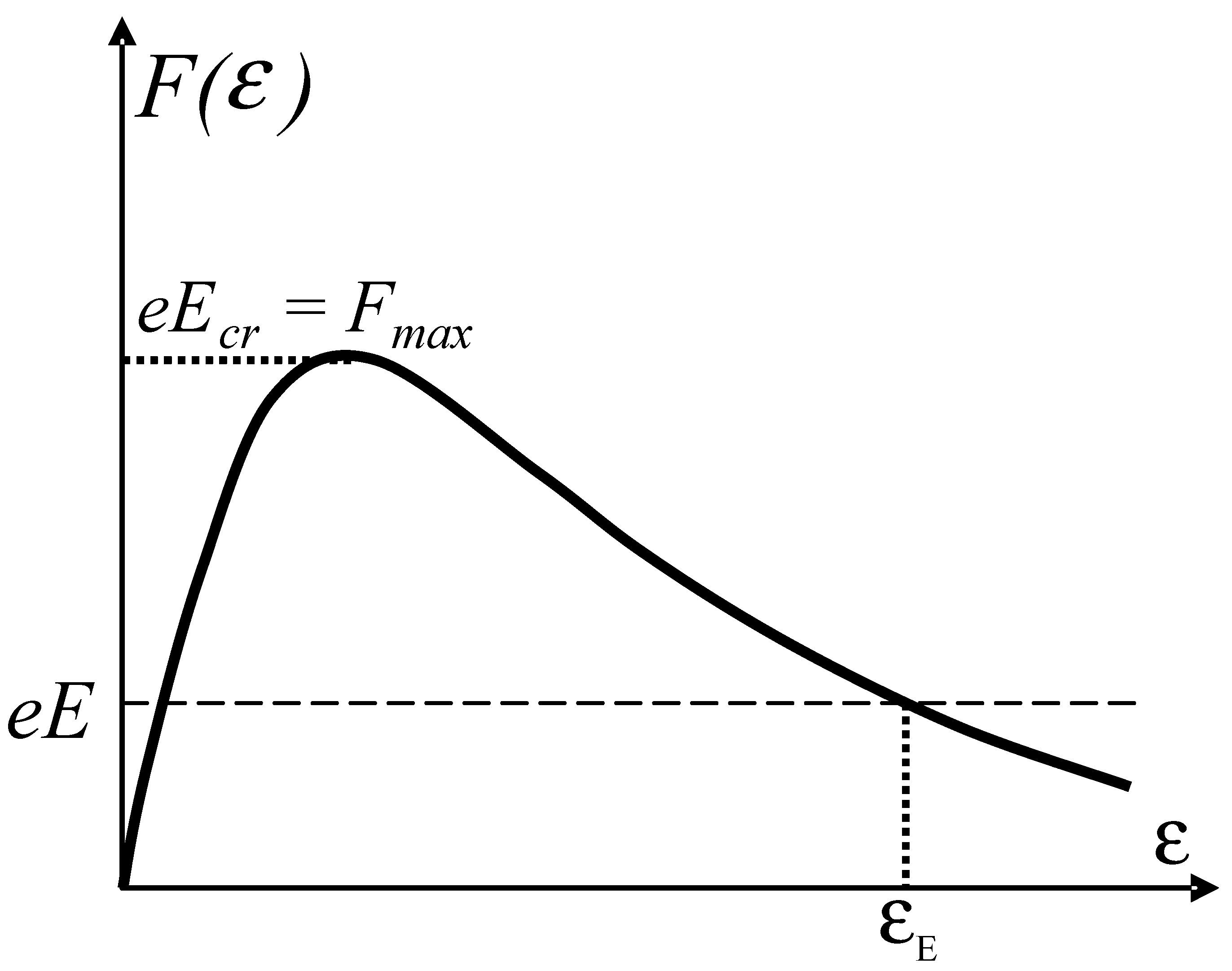
As the basis for understanding the phenomenon of the runaway electrons generated in a weakly ionized low-temperature plasma of high-voltage discharges, an asymptotically decreasing dependence of the deceleration force F(ε) of a fast charged particle (considered to be the electron below) on its kinetic energy ε is used [107,108]. Therefore, the equation for the dependence of the kinetic energy of the fast electron moving through a gas in the uniform electric field of strength E on the coordinate is traditionally written in the following form:
Here, e is the elementary electric charge, Na is the number density of atoms in the gas medium, Z is the atomic number of the gas (the number of bound electrons in the atom), and Ia is the characteristic energy depending on the gas type and very roughly quantitatively estimated to be Qualitatively, the electron deceleration force in a continuous medium is shown in Figure 1 as a function of the kinetic electron energy.
As can be seen from this one-dimensional interpretation, the critical level of the field strength is determined by the maximum deceleration force . It is also seen that if the fast electron is injected into the gas with sufficiently high energy , it can be continuously accelerated in the field, the strength of which is below the critical value . Such a continuous energy-selective mechanism specifies that a physically consecutive theory of the runaway electron phenomenon should be based on the energy distribution function for the electron ensemble. Within the limits of fluid approximation, this effect cannot be described in principle.
The stationary kinetic theory of runaway electrons in a weakly ionized plasma was first developed by Gurevich [6], who defined the probability of plasma electron transition to the continuous acceleration mode by the exponential multiplier . As the experiments showed, this probability turned out to be highly overestimated when using expression (1) to estimate the critical field strength.
We believe that in real experimental conditions, when high overvoltage across the discharge gap is maintained for only a very short time (of the order of subnanoseconds), conclusions of the stationary theory [6] cannot be used. The matter is that the frequency of scattering collisions of electrons with low energies is many times higher than that of all other processes of electron energy exchange with atomic particles in the gas medium. Therefore, the first scattering collision already deflects the electron trajectory from the direction of action of the electric force, and Equation (1) ceases to adequately describe the process of deceleration or acceleration of the scattered electron. Therefore, the decisive factors for the electron transition to the continuous acceleration mode are the scattering collisions, and exactly the transport collision cross-section σ* should estimate numerically the probability of collision of runaway electrons.
It is well known that the transport cross-section of scattering of the fast electron with energy ε on a multi-electron atom is determined by the Rutherford cross-section of scattering on its nuclear charge, Ze [108]:
where I* is the characteristic energy, generally other than Ia in Equation (1), but of the same order of magnitude.
As follows from a comparison of Equations (1) and (2), the transport cross-section decreases with increasing kinetic energy of electron faster than the deceleration force and depends stronger on the atomic number Z of the element. Therefore, Equation (1) applies to the electron moving in the uniform electric field E if during movement, it does not scatter at large angles. The probability of this event P(0) (the absence of scattering), even in the gap of infinite length, turns out to be finite and can be estimated from the following formula (see work [54] and Chapter 3 of work [109]):
The characteristic field strength obtained turns out to be significantly higher than the critical strength Ecr derived from the Bethe decelerating force. New estimates of the reduced critical field strengths reported on p. 113 of Chapter 2 of work [109] were 210 V/cm·Torr for helium (He), 1410 V/cm·Torr for nitrogen (N2), and 6790 V/cm·Torr for sulfur hexafluoride (SF6). These new values of the critical field strengths allowed calculating the number of fast electrons under experimental conditions much more accurately than previous ones.
2.2. Kinetic Model of the Runaway Electron Effect
As indicated above, the mathematical apparatus of the kinetic Boltzmann equation for the electron velocity (momentum) distribution function should be the main approach to a theoretical description of the runaway electron effect in a pulse discharge. Unfortunately, this problem cannot be solved numerically in the complete formulation (for the 3D3V model) even using modern computers. Therefore, the one-dimensional problem (for the 1D1V model) is conventionally solved [38,66] with field inhomogeneity near the cathode, for example, in the coaxial electrode geometry with current flowing radially between the cathode of small radius and the anode of large radius .
In the overwhelming majority of practical situations, the runaway electrons are generated during a very short time (less than one nanosecond), during which the discharge gap can still maintain a high overvoltage. Therefore, in calculations of this short breakdown phase, the movement of ions can be neglected. They appear in the gas due to the shock ionization of atoms and remain in the place of their creation. Mathematically, this is expressed via the neglect of ion current when calculating the electric field.
The mathematical problem formulation, even in the minimal configuration (nonrelativistic velocities and stationary ions), should describe the evolution of the momentum distribution function of the electron ensemble (here and below, m is the electron mass) and the dynamics of the electric field . Examples of such a minimal model are the kinetic Boltzmann equation (Equation (4)) and the Maxwell equation (Equation (5)) for the total current (the particle current plus the displacement current), which describe the law of conservation of the radial current per unit length in the coaxial discharge gap:
The two terms in the parentheses on the right-hand side of Equation (4) describe inelastic electron collisions with atoms, including the ionization-induced multiplication process, and the last term describes the electron scattering effect. Within the limits of the present review, we will not delve deeply into a description of inelastic collisions because this complicated question has already been analyzed in detail in our previous work [66]. For the one-dimensional problem, it is impossible to describe adequately elastic scattering; therefore, the forward–backward scattering approximation,
is conventionally used to solve it. To take into account the discharge current , it is necessary to supplement the system of Equations (4) and (5) with the equation for the current in the external electric circuit. Thus, it is possible either to fix the voltage applied to the gap or to calculate it from the Kirchhoff equation for the circuit.
The initial condition for the formulated problem was to set the initial electron concentration in the gap (uniformly or non-uniformly distributed along the coordinate). The discharge process was initiated by the generator voltage with a given amplitude gradually increasing from zero applied to the gap; furthermore, .
The system of Equations (4) and (5) (plus the electric circuit equation) was solved numerically for a uniform coordinate and momentum grid using modern computing methods.
3. Results of Modeling
The results of modeling the high-voltage discharge in nitrogen at atmospheric pressure are presented below. The only characteristics of the gas type were the known parameters of two elementary processes, namely the shock ionization and transport cross-sections [110]. This model does not require any additional semiempirical dependencies or correcting parameters.
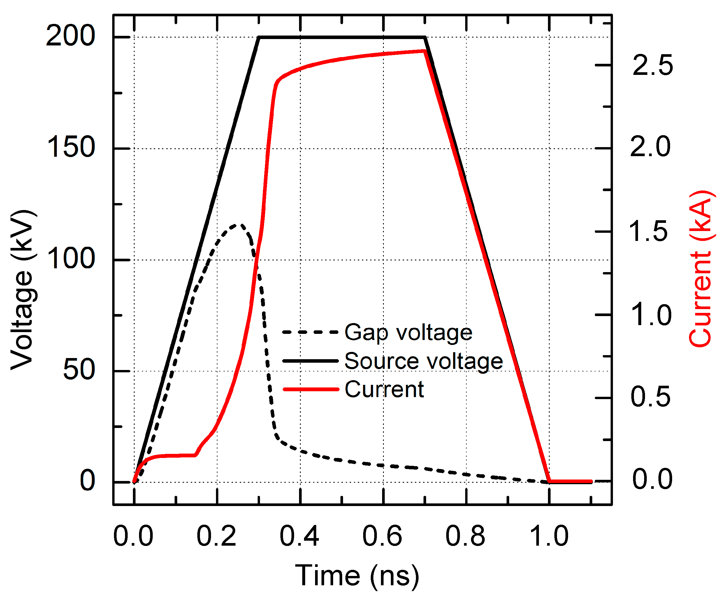
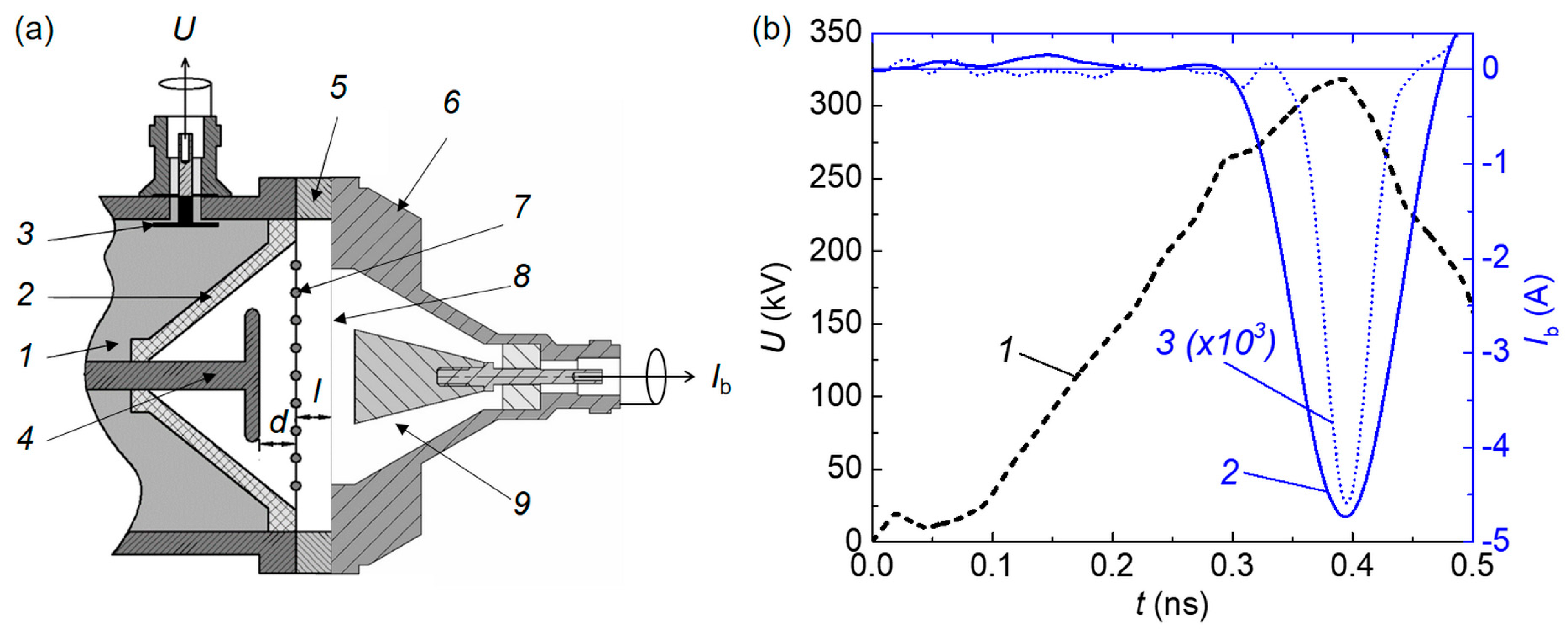
The voltage pulse with the amplitude U0 = 200 kV, linear leading pulse edge, and 1 ns base duration (shown by the solid curve in Figure 2) from a power source was applied to the coaxial gas-filled diode (with the cathode radius rC = 1 mm, anode radius rA = 11 mm, running length L = 1 cm, and nitrogen at a pressure of 760 Torr). The diode was connected in the circuit in series with the ballast resistance R = 75 Ω. We studied the process of multi-electron gas breakdown initiation, assuming an initial electron number density of 103 cm−3.
As seen in Figure 2, the current in the discharge already almost reaches its maximum value of 2.5 kA within the first 300 ps, but the voltage on the gap does not exceed 120 kV, and the discharge enters the commutation stage at 350 ps.
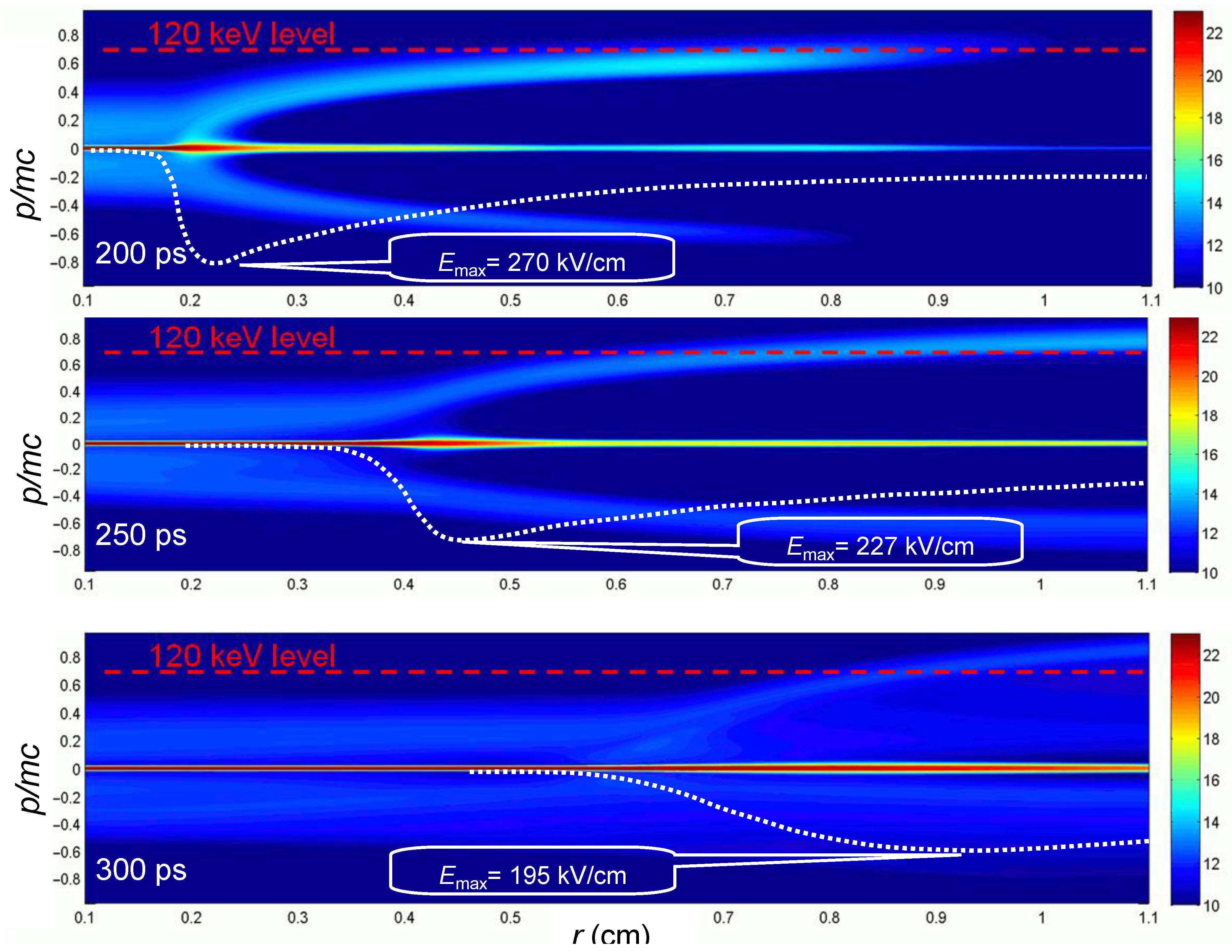
Basic information on the occurrence of the runaway electrons can be obtained from the calculated electron energy distribution function. Figure 3 shows the instantaneous functions in the radius–momentum phase plane calculated at three characteristic times of the gap breakdown stage.
The negative momenta in the figure corresponds to the scattered electrons moving (toward the cathode) against the electric field force. The dashed straight line at 120 kV is drawn for the convenience of our analysis; it corresponds to the voltage amplitude on the discharge gap, as seen in Figure 2.
Under conditions of such a fast breakdown, the Maxwell displacement current may constitute a significant (and sometimes even main) part of the total current flowing in the discharge circuit. So, at time 200 ps (the top frame in Figure 3), even the runaway electrons have no time to reach the anode, but the current in the circuit reaches 250 A because a highly conductive dense plasma has already been formed near the cathode (the internal electrode). The highly conductive plasma front is clearly seen on the phase portraits in Figure 3 since the runaway electron flow starts to be formed exactly here. In this local area (quickly moving toward the anode), the maximum field strength (270 kV/cm) is observed, the electron ensemble is strongly heated, and the probability is high that the electrons from the tail of the distribution function enter the continuous acceleration mode.
By the time (250 ps) at which the voltage amplitude is reached in the gap, the runaway electron current on the anode reaches its maximum value, and the maximum energy in their spectrum exceeds the instantaneous value of the applied voltage, as is well seen in the middle frame of Figure 3. By this time, the runaway electrons moving ahead of the dense plasma front due to ionization by collisions have already noticeably ionized the gas in the entire gap, and the first plasma electrons also reach the anode. By this time, the maximum field strength (227 kV/cm) at the dense plasma front has already considerably decreased; therefore, the probability of transition to the runaway mode greatly decreases as well.
Therefore, at 300 ps, the discharge current becomes high enough (greater than 1 kA) so that the voltage across the gap begins to decrease due to the ballast resistance in the voltage circuit. The entire gap is filled with dense plasma, although there is a long tail of a few fast electrons in it, as seen in the bottom frame of Figure 3. In the logarithmic color scale, the fast electrons are clearly seen in the picture, but their density did not exceed 10−6 of the total number of electrons in the volume. The field strength between the plasma front and the anode is leveled, remaining at a sufficiently high level. This field strongly affects the runaway electrons, accelerating them to anomalously high kinetic energies.
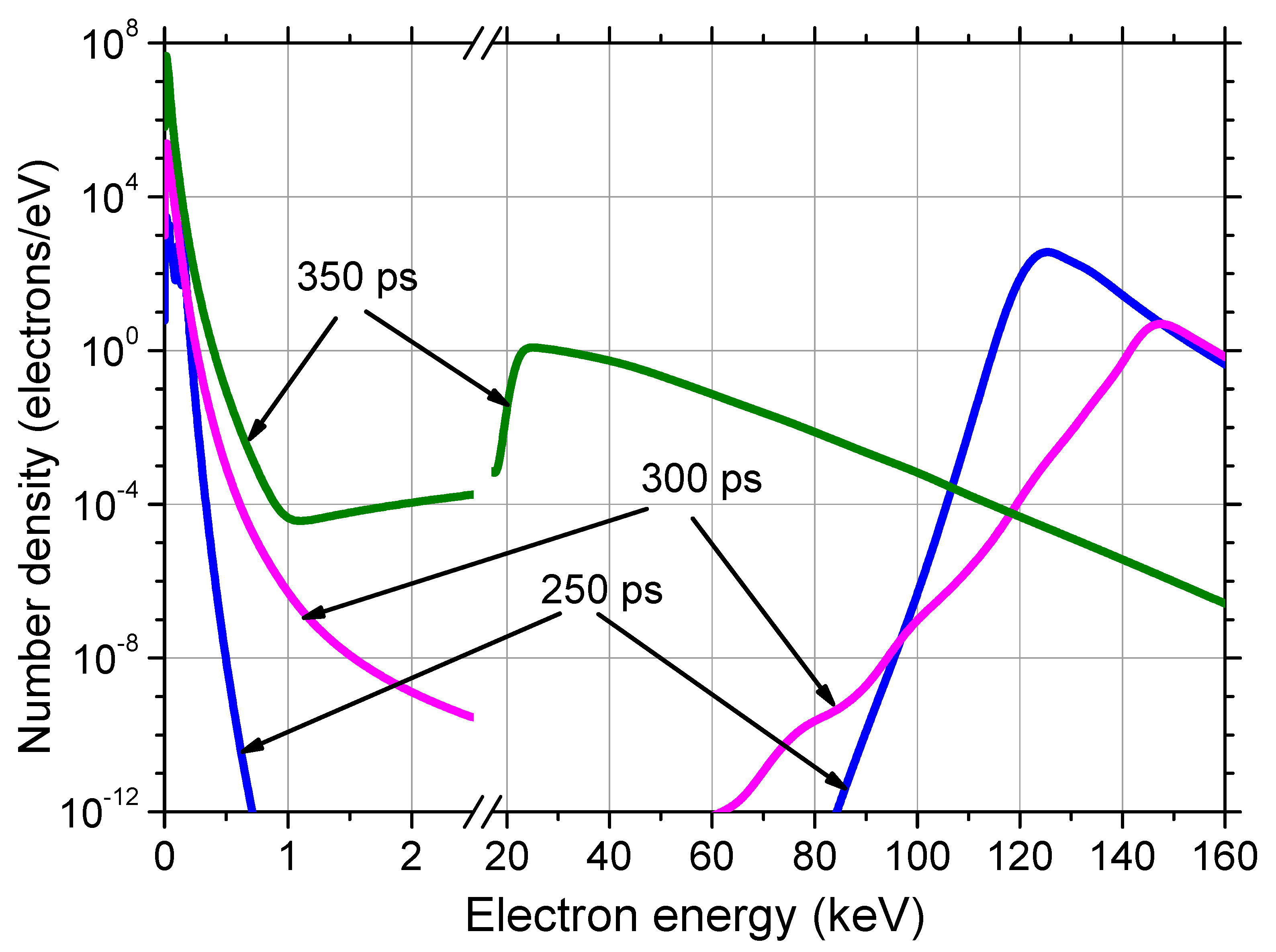
Figure 4 shows the instantaneous power spectra of the electrons arriving at the anode surface at different times. No one electron has time to reach the anode within 220 ps.
The runaway electrons are usually registered behind the thin foil placed in the anode plane. Only sufficiently fast electrons passed through this foil to the detector, thereby protecting the detector circuit from a very high plasma electron current. The plasma electrons in Figure 4 have energies below 200 eV, whereas the runaway electrons have energies above 20 keV. We consider the electrons fast with energies > 200 eV up to a few keV; they can reach the anode, but their energy is insufficient to cause them to escape from the gas diode.
To compare with experiments, the current of runaway electrons passing through the Al foil with the thickness D = 10 μm was calculated. In the calculations, the electron transmission coefficients from work [111] were used. Figure 5 shows the total spectrum of the electron beam passed through the anode foil in time T = 1 ns calculated from the formula .
A large portion of electrons with the so-called anomalously high energies [8,9,14] can be seen in the runaway electron spectrum. However, this observed effect has a natural explanation clearly understood from the three phase portraits are shown in Figure 3 [68].
For the one-dimensional problem with coaxial discharge gap geometry, a number of intermediate conclusions can be made based on the results of fast breakdown modeling:
- The energies of the overwhelming part of the runaway electron flow are taken from the high-energy tail of the plasma ensemble under the action of the strong electric field near the cathode (with a small curvature radius). This process takes place at the plasma front near the cathode, where the high plasma electron density is combined with the high electric field strength.
- In the process of plasma front propagation, the maximum strength in its vicinity decreases, and the intensity of fast electron generation decreases noticeably.
- The runaway electrons at the dense plasma front create secondary electrons, which also multiply like an avalanche. A fast plasma production in the zone between the plasma front and anode promotes the leveling of the field strength, which, in this case, cannot provide the transition of plasma electrons to the continuous acceleration mode.
- The field strength continues to increase due to the field compression between the quickly moving plasma front and the anode, thereby providing additional acceleration of a part of the runaway electrons to anomalously high energies.
Taking into account the theoretical pattern, it is possible to constructively analyze various experimental results.
4. Experimental Installations and Measurement Procedures
4.1. Generators, Cathodes, and Collectors for Forming and Measuring the RAEB
In the first works [10,11,12,13,14,15,16] where X-ray and RAEB were registered, generators of high voltage pulses with comparatively long fronts and large diameters of transmission lines and gas diodes were used. The cathode and anode design was non-optimal for obtaining the runaway electron beam currents of several ten amperes (see Figure 5.1.1 of work [16]). In addition, the RAEB registration sensors and the employed oscilloscopes had insufficient time resolution. Over the last 20 years, the generators, beam registration sensors, and gas diode designs have been significantly improved, and oscilloscopes with picosecond time resolution have appeared. All these have allowed researchers to experimentally obtain the main laws of changes in the RAEB parameters attendant to changes in the amplitude and voltage pulse front as well as the pulse shape, cathode and gas diode designs, gas type and pressure, voltage pulse repetition frequency of the generator, and its lifetime. The registered RAEB pulse durations were analyzed in Chapter 7 of work [112] and in works [31,40,95,97]. Data on the RAE bremsstrahlung and characteristic X-rays were obtained (see collective monographs [32,109,112]). It was established that under conditions of RAEB generation, the diffusion discharge is formed in the gaps with a non-uniform electric field filled by different gases at high pressure due to the development of wide streamers [30]. All this allowed new data on the RAEB parameters to be obtained with high accuracy.
To analyze the obtained experimental results in more detail, we consider the design of one of the generators specially created for RAEB investigation (see Chapter 4 of work [32]). The generator with a system of capacitive dividers provided registration of voltage pulses in the discharge gap and was also equipped with a collector system for measuring the beam current pulses or the runaway electron number density. The number of electrons emitted from the entire anode foil surface was measured, and the RAEB pulses were measured with subnanosecond or picosecond time resolution by reducing the size of the receiving collector part. Note that to obtain the picosecond time resolution, suitable connectors and cables of minimal length should be used (for example, see Chapter 7 of work [112]). To register the discharge current, the foil and the collector were removed, and the shunt based on film chip resistors or strip lines with time resolution up to ≈100 ps was inserted.
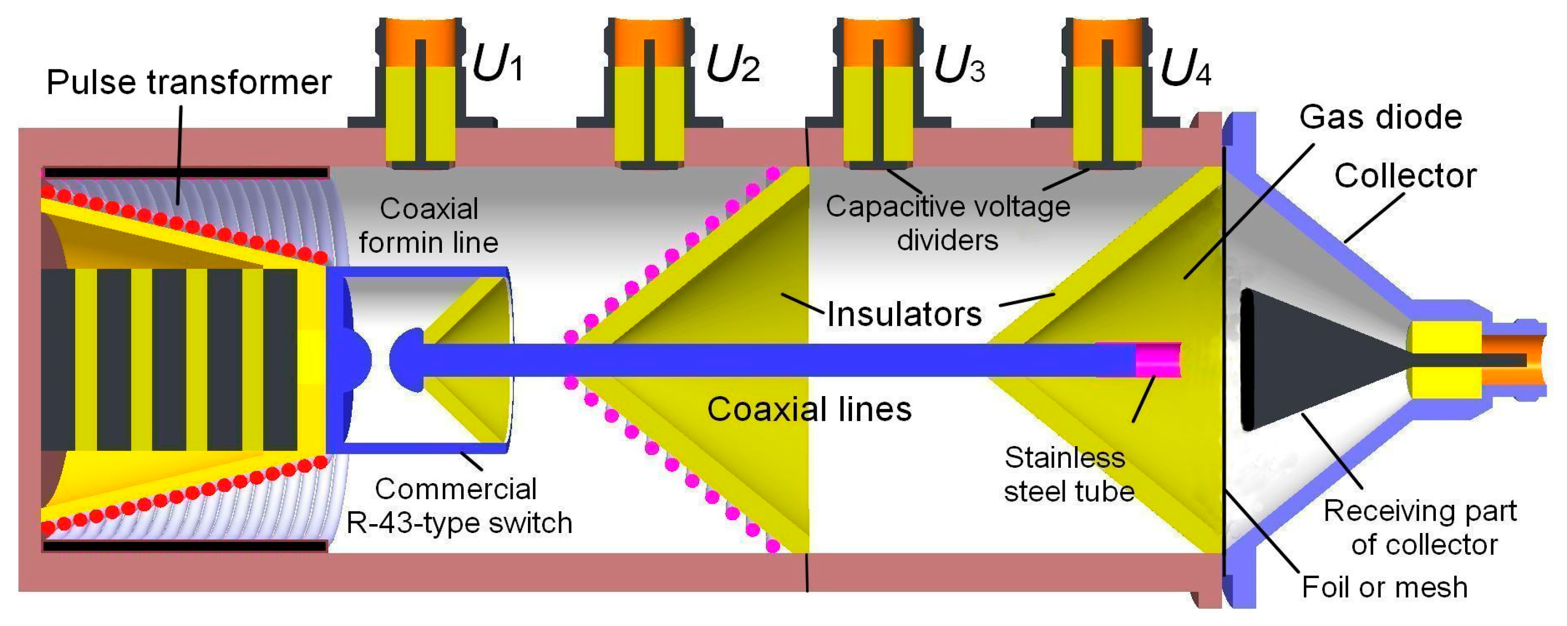
The design of the SLEP-150M generator (see Chapter 4 of work [32]) forming voltage pulses of ≈1 ns duration at half maximum and 0.25 ns pulse duration at levels 0.1–0.9 of the front amplitude is shown in Figure 6.
The SLEP-150M generator differed from the SLEP-150 generator because of the additional transmission line. In the generators, the circuit with the pulse transformer was used, inside which dielectric ring ferrite sheets were placed. The voltage pulses with amplitudes of ~4 kV generated by the additional capacitor not shown in the figure are fed to the primary winding made of the foil. The high-voltage output of the secondary winding is connected to the high-pressure spark gap R-43 shaped as a beaker. Its external surface, together with the generator housing, formed the coaxial line 4 cm long with an impedance of 20 Ω charged by the pulse transformer. After the breakdown of the R-43 spark gap, the voltage pulse is formed, which, via the short and additional transmission lines with a 100 Ω impedance, passes through to the gas diode with the cathode and the foil anode. The pulse transformer and the forming and transmission lines are filled with transformer oil.
The tubular cathode is 6 mm in diameter and made of thin foil with a thickness of 100 μm, fixed to the internal wire of the additional coaxial line, which is also shown in Figure 6. Other cathodes, the shapes and sizes of which affected the RAEB parameters, including cone-type cathodes with different apex angles, cathodes made of sewing needles, shaving edges, mesh cathodes made of thin wires, and spherical cathodes were also used.
To measure the voltage pulse parameters, capacitive sensors U1, U2, U3, and U4, described in detail in works [28,113,114], were used. Their time resolution at small receiving part diameters in the coaxial line (≤1 cm) reached ≈100 ps. The shunt based on the chip resistors or strip lines connected in parallel was used to measure the current running through the discharge gap, including the capacitive current, dynamic capacitive current, and conduction current (see Chapter 4 of work [32]). Such shunts allowed for the registration of the current across the gas diode with a subnanosecond time resolution.
The RAEB current was measured with collectors with different diameters of the receiving part. When the diameter was about 1 mm, and the special cable had a small length, the time resolution of the collector was not worse than 10 ps. When the diameter of the receiving collector part increased to 2 cm (see Figure 6), its time resolution worsened to 80 ps, but the anode foil area, behind which the beam current was recorded, increased.
In addition, in a number of experiments with this generator, the coaxial limiting spark gap was placed on the left end face of the additional transmission line, which allowed the voltage pulse duration at half maximum to be reduced to 0.1 ns, and the durations of the leading and trailing pulse edges to be reduced to 100 ps. However, in this case, the voltage pulse amplitude also decreased.
For the gas diode filled with atmospheric air, it was found that the change in the pressure, humidity, and air temperature in a laboratory room can affect the RAEB parameters. Therefore, it would be better to carry out comparative experiments in the air under identical weather conditions with monitoring of these parameters.
Note that the RAEB in works [25,28,31] was called supershort avalanche electron beam (SAEB). The term supershort was proposed because of its small duration, and the term avalanche was used because the electron avalanches appearing at the cathode play an important role in its formation. Furthermore, in the section devoted to the study of the RAEB, we use both terms (SAEB and RAEB). Note also that in a number of publications, the term supershort was sometimes translated from the Russian language by the term ultrashort; as a result, the RAE beam was also named the UAEB.
4.2. Measurement of the Parameters of the Voltage Pulses, Discharge Currents, and SAEB
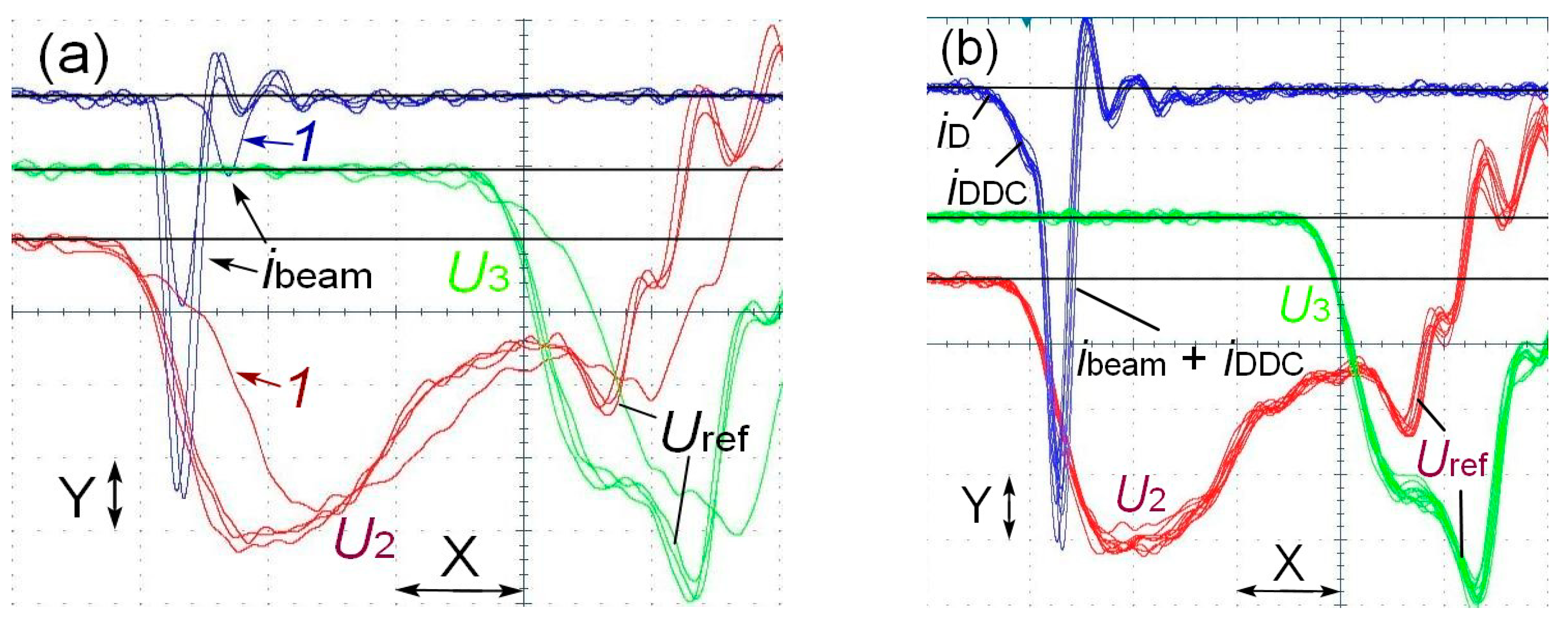
The knowledge of the voltage pulse shape and amplitude on the gas diode allows for the correct interpretation of the results obtained. Figure 7 shows a series of waveforms of voltage pulses and SAEB obtained using the SLEP-150M accelerator with the tubular cathode.
From the waveforms of the voltage pulses of the capacitor dividers U2 and U3, it can be seen that the voltage pulse fronts and amplitudes of the incident wave before the arrival of voltage pulses reflected from both dividers coincide. However, the voltage pulses Uref, reflected from the gap, arrived at different times. The delay of Uref depends on the distance between the gas diode and the capacitive divider, and it is greater for the voltage pulse U2 registered from the capacitive divider. The difference between the pulses U2 and U3 yields Uref. Moreover, it is not distorted by other reflections within the first 800 ps. The summation of U2 and Uref with synchronized fronts allows the shape of the voltage pulse U across the gap to be determined. The simultaneous measurements of the electron beam, displacement current, and dynamic displacement current allow synchronization to be performed.
In Figure 7a, the beam currents significantly decrease because of a bad response of the spark gap, an increase in the voltage pulse front, and a decrease in its amplitude (pulses 1). In Figure 7b, the SAEB pulses are shown together with the dynamic capacitive current depending on the transparency of the grid anode. The anode grid cell (0.6 × 0.6 mm) was chosen so that the DDC was several times less than the SAEB.
Using the difference between the voltage pulses U2 and U3, the reflected voltage pulse was selected, and its front was superimposed on the incident voltage wave. This allowed the voltage pulse across the discharge gap to be reconstructed. This method is widely used in pulse power techniques [115], including the study of the generation of runaway electron beams (see Chapter 7 of work [112]).
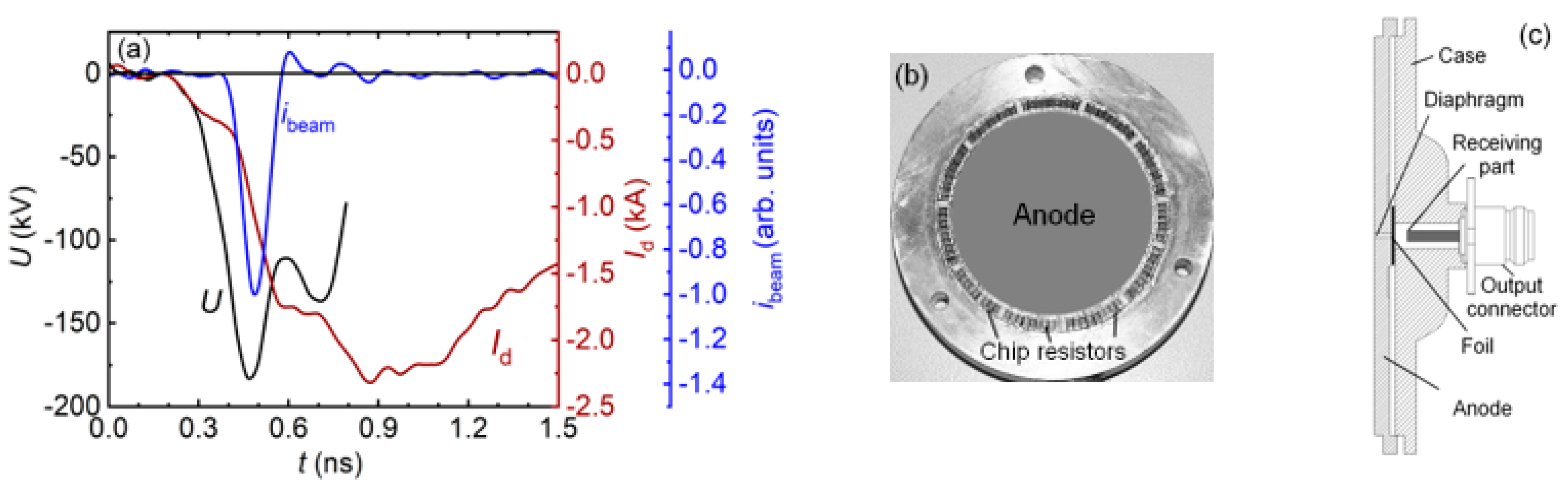
To affix the beam current pulses to the voltage pulses with picosecond accuracy, the DDC and capacitive currents were used. Figure 8a shows the reconstructed voltage pulse U across the gap, the discharge current pulse Id registered with the shunt, and the beam current pulse behind the anode foil registered with the collector having the receiving part with a diameter of 3 mm.
All three pulses were synchronized. It can be seen that the beam current is registered near the maximum of the voltage pulse and remains sufficiently high after the termination of the beam current. The shunt design is shown in Figure 8b. It was used instead of the collector and simultaneously served as the anode. The high time resolution of the collector was reached by application of the film chip resistors connected in parallel. The collector with the receiving part 3 mm in diameter (Figure 8c) was used to register beam current pulses with a time resolution of up to 20 ps. The SAEB pulse shown in Figure 8a was limited with the collector. From the U and ibeam waveforms shown in Figure 8a, it can be seen that the limitation of the SAEB duration is due to the discharge gap short-circuited by the plasma. This is in agreement with the results of the modeling presented in Section 3.
The comparison of the reconstructed voltage pulses and pulses U4 registered with the capacitive divider located opposite the center of the discharge gap (see Figure 6) showed that U4 allows registering sufficiently accurately the voltage pulse front and its amplitude but significantly distorts only its decay. Hence, the SLEP-150 (without additional transmission line and capacitive divider U2) and the SLEP-150M (with capacitive divider U4) type generators can be used to obtain dependences of the SAEB parameters on the voltage on the gas diode without application of the reconstruction technique based on reflected pulses.
5. Experimental Data
5.1. Influence of Various Factors on the SAEB Parameters
5.1.1. Influence of the Pulse Amplitude and Front Duration on the Voltage Pulse
As is well known from experimental research and modeling of the parameters of runaway electron beams, the beam current, electron energy, and pulse duration are influenced by various factors (for example, see [16,32,109,112]). In this Section, changes in the SAEB parameters accompanying variations in the voltage pulse amplitude and front duration are demonstrated. The SAEB was measured behind the thin foil anode and, in some cases, behind the dense grid anode. The grid anode was used for simultaneous registration of the capacitive current and dynamic capacitive current used to affix the SAEB to the voltage pulse [31,32,44]. In addition, the use of the grid anode allowed one to register beams with low electron energy, at the level of 10–20 keV and less, generated at low reduced electric field strengths or when the voltage pulse duration increased to hundreds of nanoseconds. It was established (for example, see works [31,32]) that the SAEB amplitude depends significantly on the voltage pulse amplitude and its current front duration.
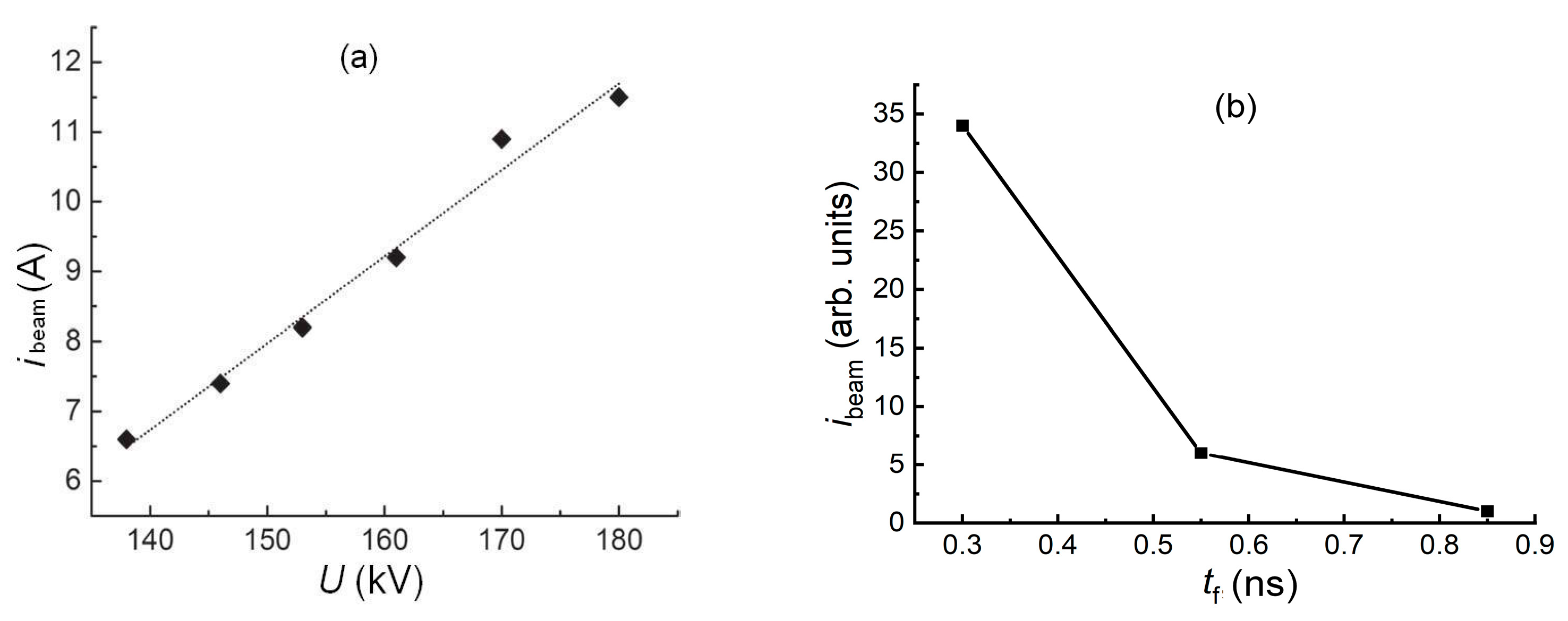
The results of measurements using the SLEP-150M generator (Figure 6) with subnanosecond time resolution are shown in Figure 9.
Since the first works [10,11,12,13,14] (see also monographs [16,32] and the references within them) in which results of investigations of X-ray, runaway electron beam, and bremsstrahlung parameters were studied under the influence of the SAEB, it was established that the runaway electron current increased with the voltage amplitude on the gas diode. The dependence obtained for the cone-shaped collector with a receiving part diameter of 2 cm is shown in Figure 9a. However, it should be kept in mind that similar dependencies were only obtained in measurements of the voltage on the cathode–anode gap. In the dependence of the beam current amplitude on the generator voltage amplitude due to the inductivity of connection with the electrodes, the beam current decreased with increasing generator voltage [36]. This is due to the breakdown of the gap at the voltage pulse front.
The improved time resolution of the registration system allowed one to establish a significant effect of the voltage pulse front duration on the SAEB amplitude (Figure 9b). Moreover, the decrease in the beam current was affected not only by a decrease in the breakdown voltage with increasing voltage pulse front duration but also by processes occurring in the gas diode. The dependence shown in Figure 9b was obtained at the same voltage (≈200 kV) on the gap due to the choice of voltage pulses with the same amplitudes and corresponding beam current pulses from the series of ~100 accelerator switches. From the figure, it can be seen that the reduction in the voltage pulse front to 0.3 ns leads to a significant increase in the SAEB amplitude. Systematic studies of the effect of the voltage pulses with durations of 0.2 ns and less on the beam current amplitude have not yet been carried out. However, from the data of work [116] in which the voltage pulse with an amplitude of 1.4 MV and 0.1 ns rise time was used, the runaway electron beam current behind the anode foil did not exceed 16 A, whereas in Chapter 4 of monograph [32] it was reported that the SAEB current with an amplitude of 100 A and pulse duration at half maximum of 100 ps was recorded behind the Al foil 10 μm thick, which corresponded to the RAE number behind the foil equal to 6.2 × 10¹⁰. In these conditions, the generator voltage pulse amplitude was 400 kV, and the voltage pulse rise time on the level 0.1–0.9 was 0.25 ns.
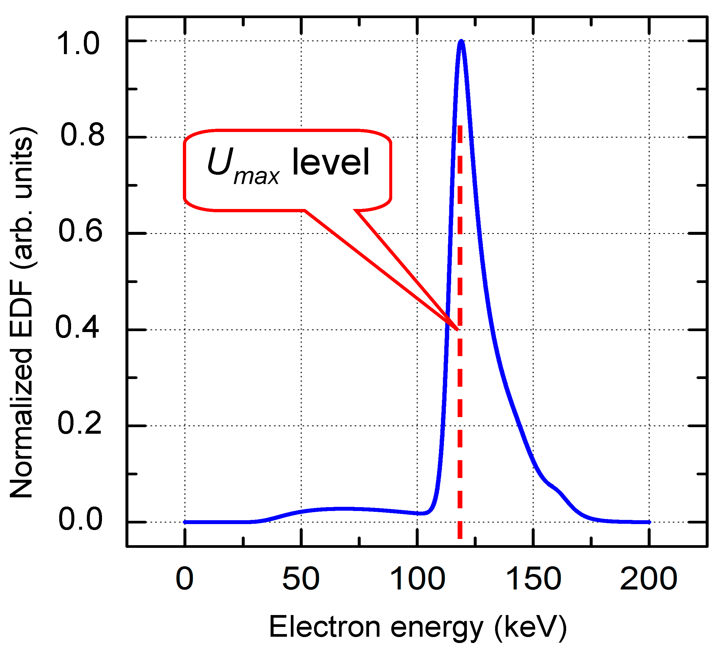
5.1.2. Runaway Electron Energy Distribution
This parameter is very important for understanding of physical processes occurring during RAE generation and for the practical application of the SAEB. However, experimental data on the runaway electron beam spectra obtained by various scientific groups differ significantly. Results of investigations performed at the HCEI showed that in the SAEB spectrum generated in the air at atmospheric pressure, two to three groups of electrons with different energies could be identified [28,31,32]. The basic (second) group of electrons has energies in the range eUm/3 <T2 ≤ eUm, where Um is the maximum voltage on the gap and e is the electron charge. The first group of electrons has energies T1 ≤ eUm/3. To measure the electrons of the first group, thin foils or metal grids with small cell sizes (less than 0.2 × 0.2 mm) should be used. This allows one to avoid the effect of the dynamic displacement current on the collector readings [44]. The electrons of the third group have energies T3 > eUm; they are called the electrons with anomalous energy. The number of electrons in each group depends on the experimental conditions, voltage pulse parameters, and design of the cathode and gas diode. To increase the number of electrons in the third group, the voltage pulse rise time should be reduced, and cathodes with increased curvature radius should be used. However, even in conditions close to optimum for SAEB generation, the number of electrons of the third group is low and does not exceed 10% of the electron number behind the aluminum anode foil with a thickness of 10 μm.
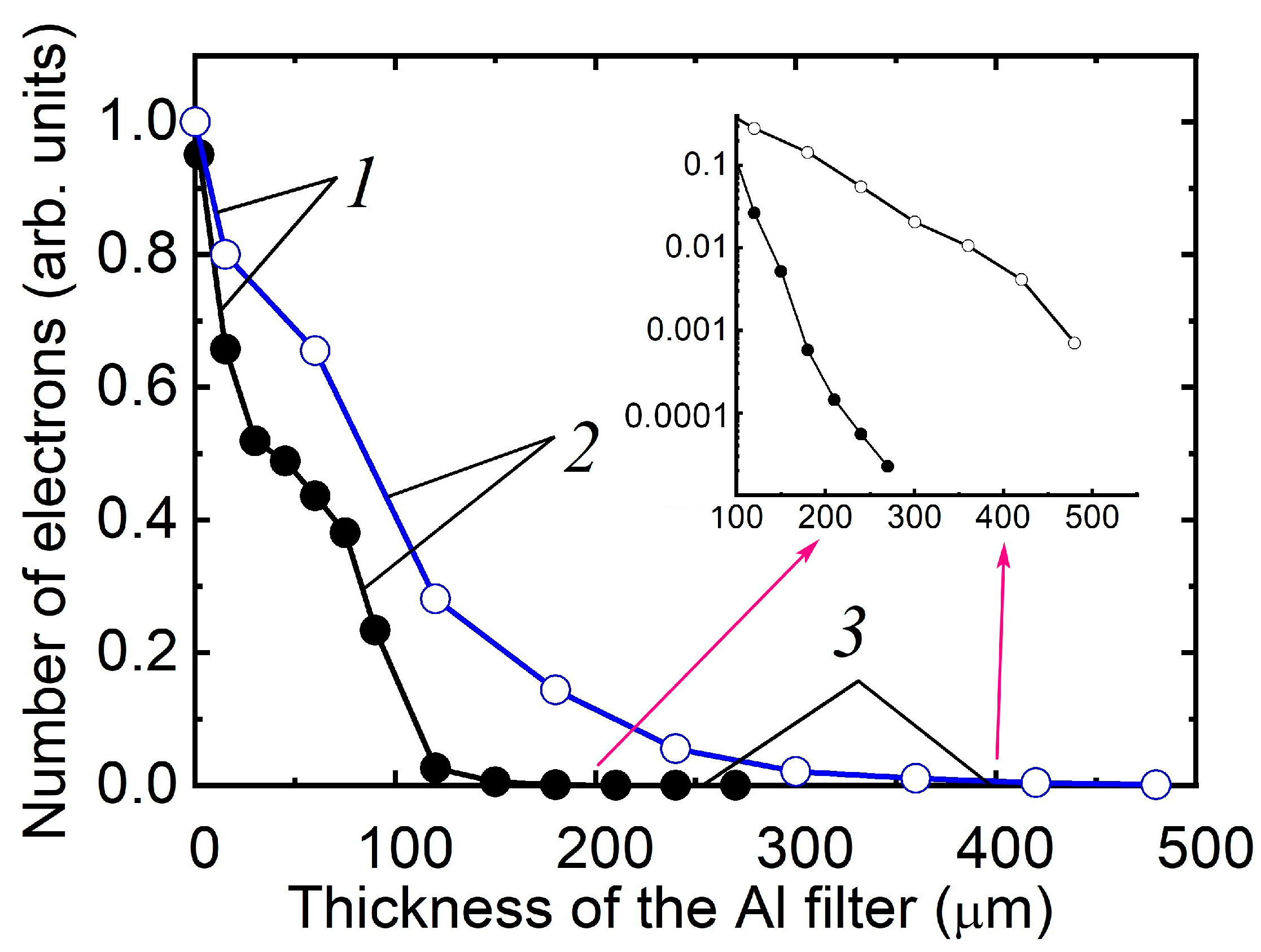
Figure 10 shows the results of investigations of the runaway electron beam spectra generated in the gas diodes; a part of them was presented in work [117].
Three sections designated by the figures can be seen in all experimental curves, with obvious inflections in transitions from one section to another. Section 1 reflects the contribution of the electrons of the first group with comparatively low energies. Section 2 corresponds mainly to the electrons of the second group—the main group in the SAEB. Section 3 indicates the electrons with energies T3 > eUm and shows that their number is comparatively low.
To reconstruct the spectrum, the method developed by A. V. Kozyrev and V. Yu. Kozhevnikov [117] was used that allows the electron beam spectra to be determined under minimal a priori assumptions using regularization of the ill-posed problem solution of the Fredholm integral equation of the first order. The main requirement for the reconstruction of the electron spectrum is a sufficiently smooth decay curve. Therefore, to calculate the spectrum, the experimental decay curve, if required, should be approximated by a smooth dependence.
5.1.3. Influence of the Cathode Material and Shape on the SAEB Parameters
The electrode material and design significantly affect the parameters of supershort avalanche electron beams generated by nanosecond discharges in air and other gases at atmospheric pressure. Systematic studies of the influence of the cathode material on the SAEB amplitude and X-ray density were carried out in work [45] for tubular cathodes, gas diodes filled with air at atmospheric pressure, and high-voltage pulses with different rise times (0.3, 1, and 15 ns). The gap was formed by the flat anode and tubular cathode made of different metals (stainless steel, permalloy, titanium, niobium, copper, brass, or aluminum). On the installation with a voltage pulse rise time of 0.3 ns, it was established that the voltage amplitude on the gap depends on the tubular cathode material and reaches its maximum value for the stainless-steel cathode. The maximum SAEB amplitudes were reached, with other things being the same, in the conditions of the maximum voltage on the gap. It was assumed that the voltage amplitude on the gap changes due to different thresholds for electron emission from a metal surface. For voltage pulse rise time of 1 ns and less, the SAEB amplitude increased for the metal cathodes with low work function.
When the voltage pulse rise time increased to 15 ns and the interelectrode gap length increased to 8 cm, the cathode material ceased to affect the voltage amplitude on the gap and the intensity of X-ray from the gas diode. The X-ray density, measured in work [45] using a NaI scintillator and a photomultiplier, was independent of the cathode material.
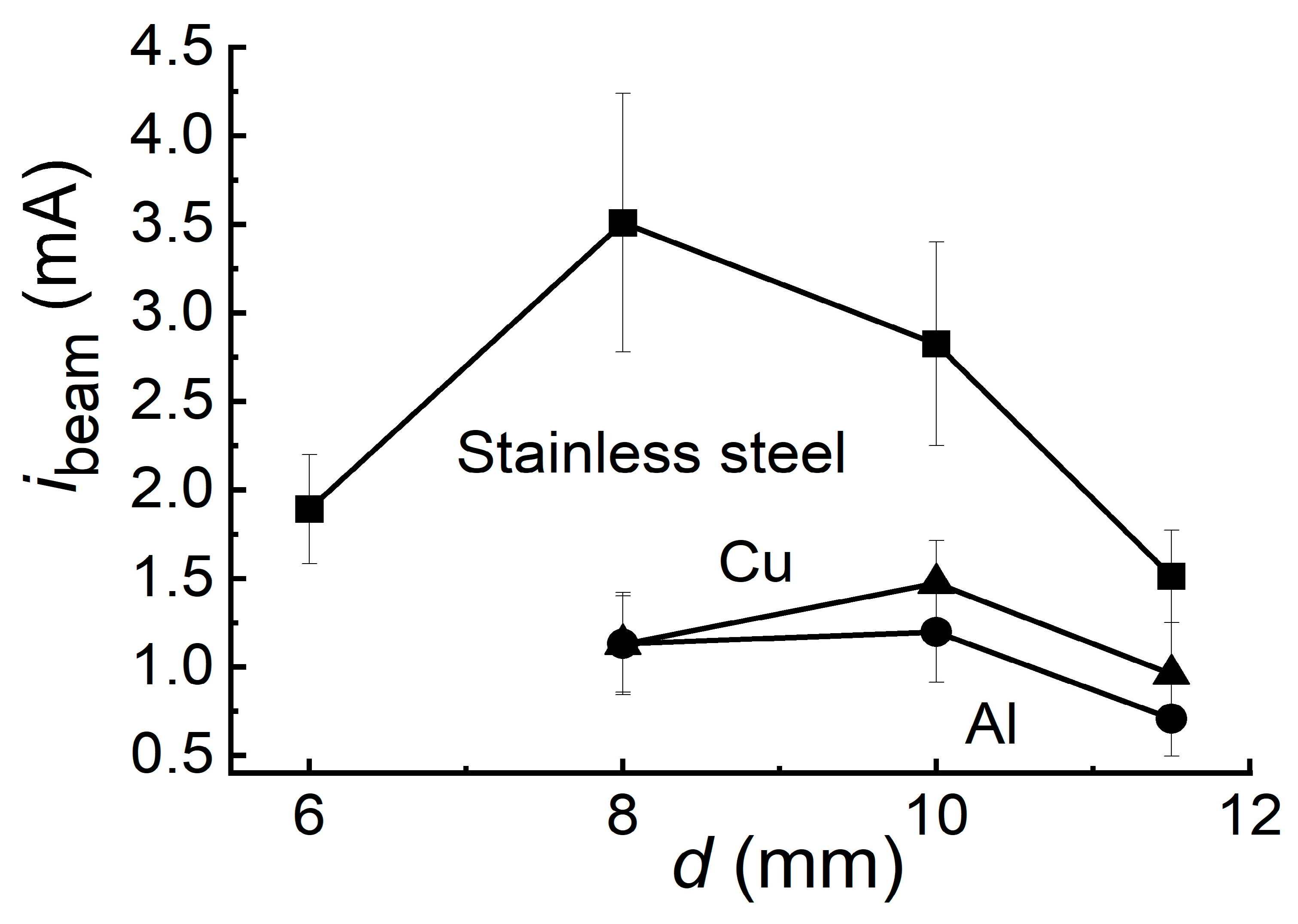
The results similar to those reported in work [45] were also obtained using the SLEP-150M generator with the cone cathode and voltage pulse rise time of 0.3 ns, and the effect of the interelectrode gap was also demonstrated. In these experiments, the SAEB amplitudes and the voltage amplitudes on the gap were measured during SAEB generation. The cone cathodes, made of copper, aluminum, and stainless steel with cone apex angles of 90°, were used. The dependences of the SAEB amplitude registered via the collimator hole with a diameter of 1 mm placed after the anode foil on the interelectrode gap length is shown in Figure 11 for the indicated cone cathode materials.
Each point was averaged over 10 pulses. The optimum interelectrode gap length was 8 mm for the cone stainless steel cathode, whereas for the copper and aluminum cathodes, it was 10 mm. The average voltage pulse amplitude on the gap, reconstructed from the incident and reflected waves for the interelectrode gap 10 mm long and the cone stainless steel cathode, was ~120 kV, whereas for the copper and aluminum cathodes, it was ~100 kV. In what follows that, the maximum SAEB currents were obtained for the cone stainless steel cathode providing the maximum voltage on the gap. This coincides with the results of work [45] in which the tubular cathodes were investigated. Unlike the results of measurements of the beam current from the foil surface with a diameter of 2 cm with the tubular cathode (see Chapter 1 of [112]), the interelectrode gap had no significant influence on the SAEB pulse duration on the gas diode axis in measurements of the beam current transmitted via the collimator hole 1 mm in diameter with the cone cathode. The current pulse duration at half maximum was greater than the limiting time resolution of the registration system and was ~30 ps at half maximum. The distinctive feature of the SLEP-150 generator with the cone cathode is the formation of a clearly pronounced cathode spot at the cone apex and the reduction in the SAEB current amplitude.
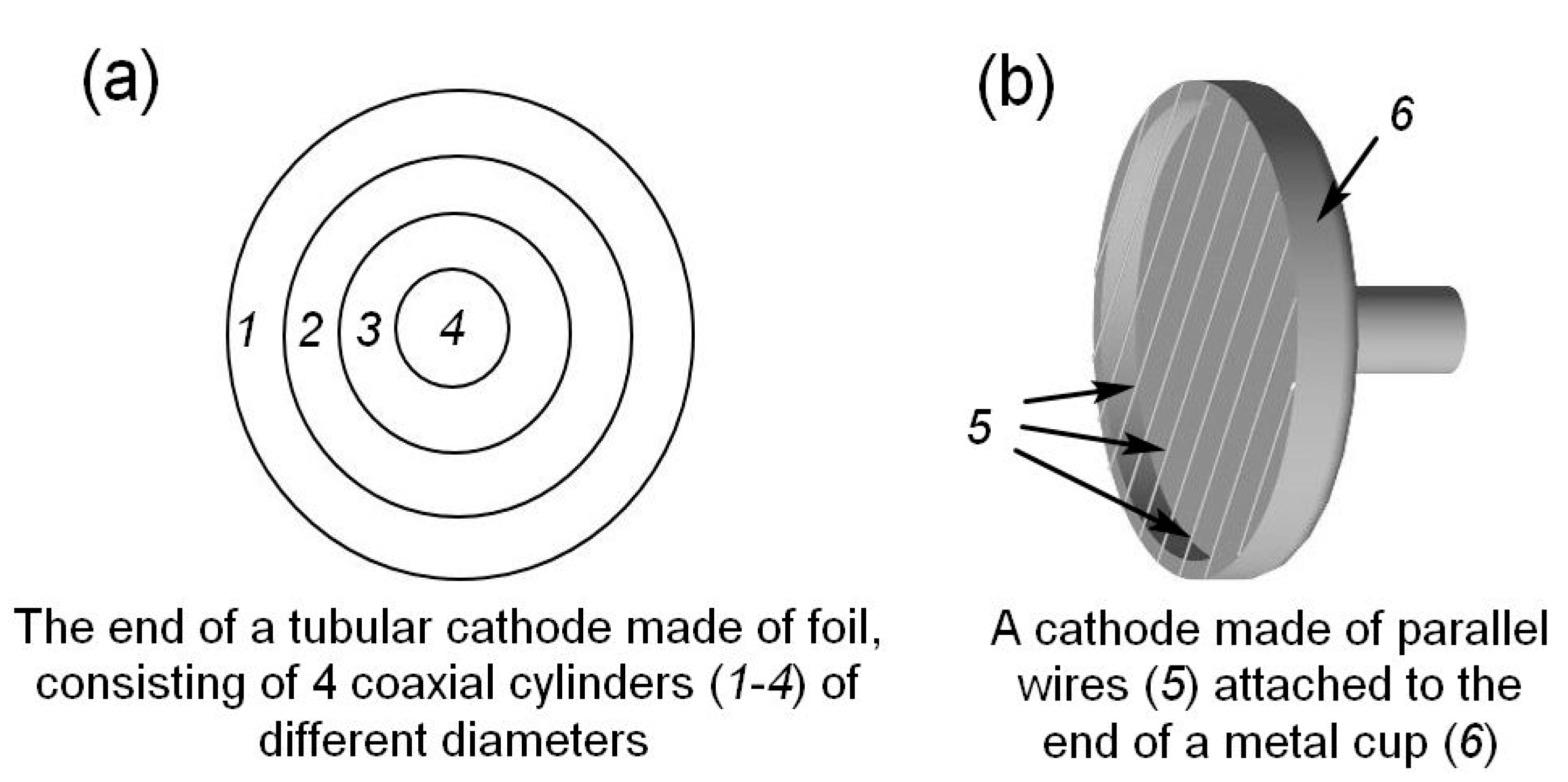
The influence of the cathode shape on the SAEB amplitude was studied in ample detail using the SLEP-150 and SLEP-150M generators (see Chapters 1 and 4 of work [32] and Chapters 1 and 7 of work [112]). The RADAN-220 [113] and FID generators [118] were also used. Six cathodes were applied. Cathode No. 1 (tubular one) represented the stainless steel tube and was 6 mm in diameter made of foil with a thickness of 100 μm. Cathode No. 2 (spherical one) represented the steel sphere with a diameter of 9.5 mm. Cathode No. 3 (grid one) represented the grid with a step of 4 mm from parallel wires and was 0.2 mm in diameter, fixed on the end face of the hollow cylinder 3 mm high, 40 mm in diameter, with a disk bottom. The distance from the wires to the bottom was 1.5 mm. Stainless steel cathode No. 4 (cone one) had an apex angle of 82° and a rounding radius of the cone apex of ~0.1 mm. The cone base had a diameter of 6 mm and passed into the cylinder of the same diameter. Cathode No. 5 (blade one) was fabricated from a razor blade 7 mm long fixed on the end face of the tube made of foil 6 mm in diameter. Tubular cathodes of large diameters (up to 60 mm) were also used, including the cathodes consisting of several tubes of different diameters coaxial with the central axis [25].
The flat anode of the gas diode (Figure 6) was made of aluminum foil with a thickness of 10 μm reinforced by the grid with transparency up to 90% of the diaphragm. To obtain the maximum beam current amplitude, the anode should be made of metal with a small atomic number and the least thickness. At the same time, it should have high strength to maintain the pressure drop between the gas diode and the collector. In addition, the shock waves generated by diffusion or spark discharges in gas diodes should be taken into account.
It was found that to increase the SAEB amplitude, it is necessary to use cathodes with a long sharp edge, including cathodes with several coaxial tubes of different diameters (Figure 12a).
The maximum amplitudes were obtained using a grid cathode made of parallel stainless-steel wires (Figure 12b). The SAEB current with amplitude of ≈100 A and duration at half maximum of 100 ns, which corresponded to the RAE number behind the foil equal to 6.2 × 10¹⁰, was obtained behind the Al foil with a thickness of 10 μm. With this cathode, the exposition X-ray dose was measured for the copper foil anode with a thickness of 20 μm. The largest exposition dose was 1.8 mR per pulse. The optimum interelectrode gap to obtain the maximum SAEB amplitude was ~4 mm. The SAEB amplitude decreased with the increasing interelectrode gap, but the average electron energy increased. Therefore, the optimum interelectrode gap to obtain the maximum exposition dose was longer (~5 mm) than that for the maximum SAEB amplitude.
Note that the optimum interelectrode gap depends on the design and sizes of the cathode, amplitude and rise time of the generator voltage pulse, and gas type and pressure. For the SLEP-150 generator with the tubular electrode 6 mm in diameter, it was 12 mm.
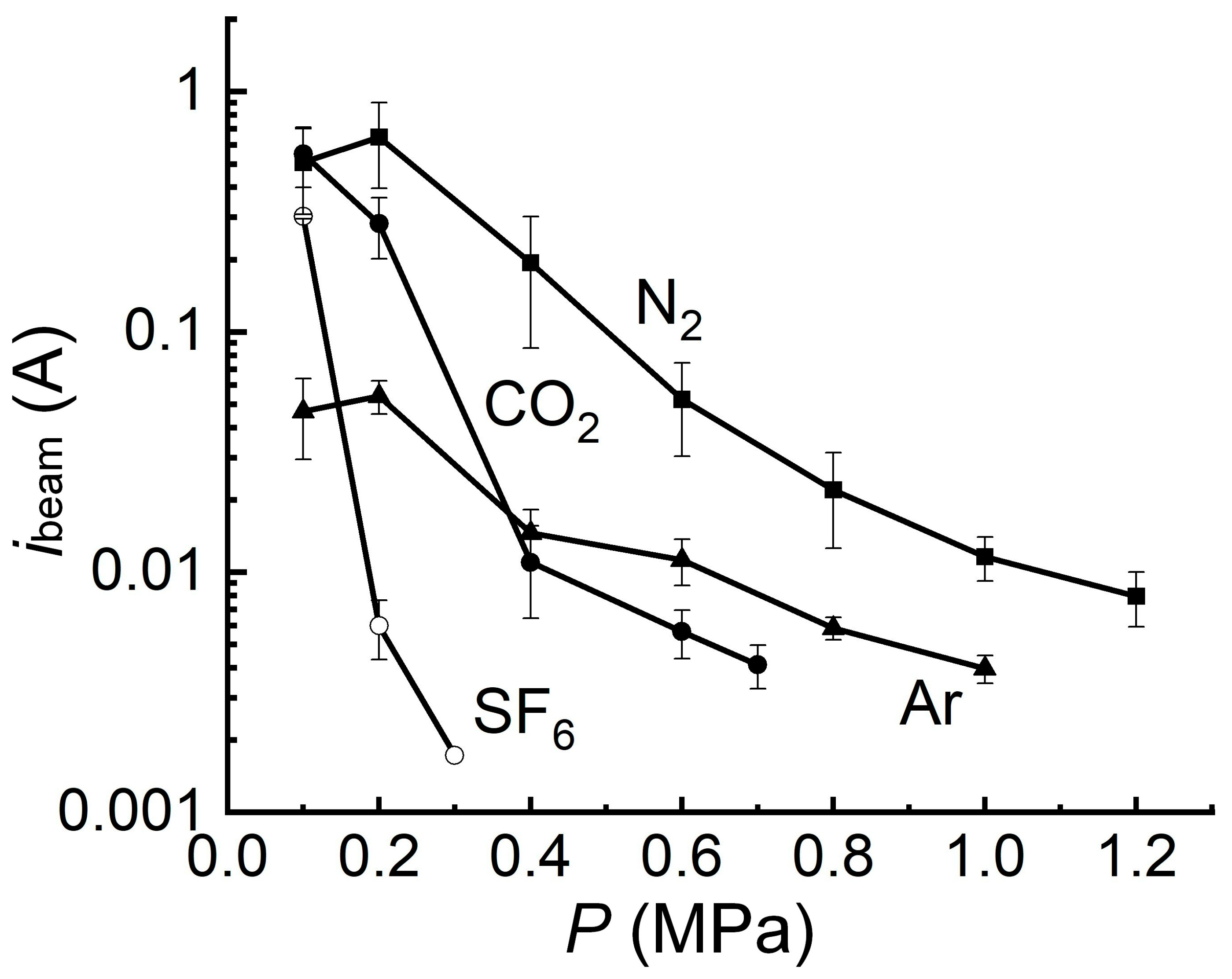
5.1.4. Influence of the Gas Pressure and Type on the SAEB Parameters
Typical dependencies of the SAEB current pulse amplitude on the pressure are shown in Figure 13.
An increase in the gas pressure usually leads to a decrease in the SAEB amplitude [119]. This is connected with the decrease in the reduced electric field strength and the increase in the electron energy losses by collisions. However, there can be exceptions for some sections of the experimental dependencies. Thus, the beam current increases when the nitrogen and argon pressure in Figure 13 increases from one to two atmospheres. In this case, this is due to the increased number of cathode spots on the tubular cathode edge and the improved discharge uniformity.
5.1.5. Generation of an RE Beam in the Direction Opposite to the Anode
This mode was implemented using a high-voltage flat anode and a grounded grid cathode, see Chapter 5 in [112]. The design of a gas diode for generating a RE beam in the direction opposite to the anode is shown in Figure 14.
In this mode, the main part of the current from the grid cathode enters the flat anode, causing bremsstrahlung X-ray radiation. However, the beam current in the direction opposite to the anode, which, in its characteristics, corresponds to the SAEB and is recorded behind an Al foil, reached several amperes. When only a fraction of a RAEB current is measured by a collector with a small diameter (3 mm) of the receiving part, its FWHM duration decreases (waveform 3, Figure 14b). An important feature of this mode is the effect of the anode material on the beam current. When using a tantalum Ta anode, the beam current was four times higher than that when using an aluminum one, and the exposure dose of X-ray radiation during a discharge in atmospheric pressure air was 3.5 mR. Apparently, X-ray radiation affects the formation and movement of an ionization wave in the direction opposite to the anode. With an increase in the intensity of X-ray radiation with the Ta anode, the beam current in the direction opposite to the anode increases.
6. Discussion
Based on our analysis of the experimental and theoretical works devoted to runaway electron generation in centimeter gaps filled with high-pressure gases cited in the present review, we can conclude that the main regularities of this phenomenon have been established by the present time. In addition, in many works the importance was indicated of runaway electron generation for the formation of various discharge forms, primarily diffusion discharges [16,32]. However, when studying the RAEB in high-pressure gases, primarily in the air at atmospheric pressure, discussions constantly arose on the electron energy distribution, the RAEB pulse duration, and the mechanism of runaway electron generation. At the present time, the number of debatable questions has decreased. This is due to improved equipment and sensors used in experimental research as well as refined theoretical models. Let us consider the results in further detail for which new data have been obtained.
The amplitude and duration of the RAEB pulse are important parameters for runaway electron generation. We already pointed out that in the first works [12,13,14,15,16] in which the runaway electron beams (RAEB) were registered in air at atmospheric pressure, the generators of high-voltage pulses with comparatively a long rise time, large diameters of the transmission line and gas diode, and non-optimal cathode and gas diode designs for obtaining runaway electron beam currents of several ten amperes were used (see Figure 5.1.1 of work [16]). In addition, sensors used for RAEB registration and employed oscilloscopes had insufficient time resolutions. Over the last 10 years, the generators, sensors for beam registration, and the gas diode design have been significantly improved. In addition, the oscilloscopes appeared with picoseconds time resolution. It was found that to obtain beams with a great number of runaway electrons behind the anode foil and, hence, a high RAEB amplitude, not only are high reduced electric field strengths and voltage pulses with short rise times required but also cathodes with extended edges and a great number of emission centers [31,32,112]. Moreover, it was established that the beam current increases for the optimum design of the gas diode shown in Figure 12 and the longitudinal electric field [97]. In the gas diode shown in Figure 12, the runaway electrons propagating at large angles to the longitudinal cathode axis [28] charge the insulator surface, thereby increasing the number of electrons registered behind the anode foil. In addition, the loss of electrons that travel to the side wall of the gas diode is reduced by increasing the area of the cathode with a sharp edge, see Figure 12.
The conducted research confirmed that the minimum duration of the runaway electron beam current was registered behind the anode foil only when measuring a part of the electron beam transmitted through a hole in the anode diaphragm, the diameter of which should be 1 mm or less [120]. It was found that RAEB pulses with two peaks were registered in some cases (see Chapter 4 of work [32]) with small diaphragms placed at the anode and cathode with extended edges with small curvature radius. This mode can be explained by non-simultaneous emission along the sharp edge of the cathode with a small curvature radius. It was shown that for voltage pulses with rise times of 0.3 and 0.7 ns, the least RAEB durations were observed with cone or spherical cathodes having a radius of ~1 cm, and one emission center was formed at the electric field maximum [120].
The occurrence of electrons with anomalous energy was caused by the Askaryan effect. The results of calculations presented in [8,9] showed that a part of electrons in the electric discharge in gases could acquire additional acceleration due to synchronous movement with electrons of the streamer or ionization wavefront. This mechanism was experimentally confirmed by the registration of electrons with anomalous energy (exceeding eU, where U is the voltage on the discharge gap; see Figure 10) as well as by the results of theoretical modeling shown in Figure 4 and Figure 5. However, in works [121,122] (see also work [16]), it was declared that the electron energy distribution maximum corresponds to an energy of 290 keV for the interelectrode gap of 2 cm and the voltage on the gap Um = 190 kV. Moreover, work [121] erroneously stated that the monoenergetic runaway electron beam is generated in air at atmospheric pressure. In that case, the main part of electrons in the beam had an energy exceeding eUm [122]. This error was repeated in the recent work [123] of this group.
There was also the third point of view on the possibility of the generation of runaway electrons with anomalous energy presented in works [34,124]. The authors of these publications considered that the maximum energy of runaway electrons generated in the air at atmospheric pressure cannot exceed eUm. As already pointed out above, the results of simulations (see Figure 4 and Figure 5 in Section 3), together with the experimental measurements shown in Figure 10, demonstrate the generation of runaway electrons with different energies, including the energy exceeding eU. As can be seen from the calculated results shown in Figure 5, the ratio of the number of runaway electrons with anomalous energy to that with energy ≤ eU is greater than in the experimental conditions. This is due to the fact that calculations were performed for a simplified geometry of the gas diode, disregarding the RAE generation at different angles.
Let us schematically describe the mechanism of runaway electron generation in the SAEB generation mode in which the maximum beam current amplitude behind the foil anode has been successively obtained to date. Four stages of the SAEB generation can be distinguished in the discharge development. The first stage corresponds to the auto-electron emission from the cathode that arises at a voltage pulse amplitude of hundreds of kilovolts at the pulse front due to macro- and micro-inhomogeneities on the cathode. As already pointed out above, the cathode should have sharp edges and a long length of the emitting surface for the generation of SAEB with maximum amplitudes. In the second stage, the electrons emitted from the cathode move to the mode of running away due to the electric field concentration on the micro- and macro-inhomogeneities of the cathode. These electrons ionize the gas near the cathode and create initial electrons from which, together with the auto-emission electrons, electron avalanches develop, transforming into a spherical streamer (an ionization wave). Accordingly, a dense cloud of diffusion plasma is formed near the cathode in a short time. In this stage, the discharge current, together with the displacement current with a subnanosecond voltage pulse front, reaches several hundreds of amperes (Figure 8), and the auto-electron emission has time to convert into an explosive one [125]. At voltage pulse durations of 0.1–0.2 ns, the corona diffusion discharge is observed near the cathode together with bright spots arising on the cathode surface. In addition, the current from the cathode is influenced by near-cathode plasma radiation. The influence of the photoemission on the beam current generation leads to the approach of the diffuse discharge to the lateral surface of the cathode (see Figure 6 in Chapter 1 of work [32]). Note that the electric field near the cathode is additionally amplified by the positive ion charge, and this also can lead to fast electron generation, including the region near the lateral cathode wall. The main RAE number is generated in the third phase and is caused by the electron acceleration between the dense polarized plasma front (the streamer front) and the anode. In the beginning, this occurs at the cathode and for a high rate of voltage change in the gap and near the anode. The electrons moving at the ionization wavefront and in the gap are affected by both the negative charge of the avalanche heads and the voltage on the anode. Note that the electric field in the gap is amplified when the streamer front approaches the anode. In the fourth stage, the ionization wavefront reaches the anode, the electric field distribution in the gap becomes more uniform, and the electron beam generation stops. In addition, after the ionization wavefront reached the anode, the voltage on the gap decreased. The voltage decay on the gap depends on the gas pressure and type. It was experimentally established that using the SLEP-150 generator, the voltage on the gap starts to decrease at 200–500 ps (Figure 8a). At this time, the streamer front and the electron beam reached the anode, and the ionization energy increased. Under these conditions, the ionization wave velocity reached ~10 cm/ns [126]. The different RAEB generation modes were described in detail in work [127].
By the present time, it has been established that the first electrons in pulsed discharges in centimeter intervals are initiated from the cathode with a small curvature radius due to auto-electron emission. In this case, the electron emission can be amplified due to micro-inhomogeneities appearing on the cathode owing to the explosive electron emission [128], and as shown in new works, the influence of mechanical stresses [129] and small particles sputtered from the cathode [130] can be observed. The electrons start to accelerate to high energies in the near-cathode zone with an enhanced electric field after the occurrence of the first electron avalanches, transforming into a spherical streamer. Furthermore, the energy of a part of initially accelerated electrons continued to increase in the decreasing electric field. At subnanosecond high-voltage pulse fronts, the runaway electron number can increase when the wide streamer front approaches the anode [30]. And this increase in the runaway electron number is manifested via the increase in not only RAEB amplitude but also its duration.
7. Conclusions
Since the origin of C. T. R. Wilson’s idea [1,24] on the possibility of electron acceleration to high energies in atmospheric discharges, runaway electron generation has been studied for about a hundred years. His idea had a significant impact on the understanding of processes occurring in gas discharges at high electric field strengths. The runaway electron generation in gases is a fundamental physical process that influences the gas medium breakdown. To realize the runaway electron mode in air or other gases at high pressure, the reduced electric field strength should exceed its threshold value. This is most easily reached in a non-uniform electric field using the cathodes with a small curvature radius. In the beginning, the electrons are accelerated in the zones of the maximum electric field, and then their acceleration continues in the lower field zone due to the reduced electron energy losses with an increase in their velocity. The reduced threshold electric field strength necessary for the formation of beams with the maximum number of runaway electrons is about 10 times higher compared to the conventional reduced electric field strength [53,54,56].
The modes of runaway electron beam generation are very diverse and depend on the voltage pulse parameters, gas type and pressure, cathode and gas diode designs, and cathode material. RAEB amplitudes of ~100 A have already been reached in the air at atmospheric pressure [31] and can be further increased. The RAEB pulses with amplitudes of several units of kiloamperes and subnanosecond pulse duration can be obtained by decreasing the gas pressure in the diode. Runaway electrons allow pulsed diffuse discharges with high specific energy contribution to be obtained that can be used to create pulsed lasers and excilamps as well as to process metal, dielectric, and semiconductor surfaces.
Due to the natural difficulties of experiments on measuring the parameters of processes in the picosecond time range, the contribution of theoretical simulation to understanding the mechanism of generation of runaway electrons may turn out to be the main one. It is now obvious that an adequate theoretical description can only be obtained using kinetic models using the method of electron momentum (velocity and energy) distribution functions [6,63,66,131,132]. Based on this description and comparison of calculations with experimental data, we can state with great confidence that the main details of this phenomenon are correctly understood. Good agreement between measurements and theoretical forecasts (number of fast electrons, their energy spectrum, trends in dependences on pressure and kind of gas, pulse power parameters, etc.) is reflected in a number of publications [30,38,42,133,134].
Theoretical simulation revealed the influence of the electrical breakdown mode on the number and spectrum of runaway electrons. Thus, when the breakdown is initiated due to the emission of electrons from the cathode surface, the number of fast electrons is almost an order of magnitude lower than in the breakdown mode with volume initiation of the initial electrons [38,135].
The kinetic theory outlined in Section 2 of this review and works [66,68] demonstrates the physical mechanism for the appearance of electrons with “anomalously high kinetic energy”. Although in experiments, the fraction of such electrons is significantly less than in calculations, this is easily explained by the difference between the one-dimensional geometry of the theoretical problem and the real three-dimensionality of the experiment.
In conclusion, note that currently, there are little-studied discharge aspects significantly affected by the runaway electron beam generation, in particular, the atmospheric discharges [16,32,136]. The runaway electron generation limits the plasma heating in installations for studying thermonuclear synthesis. The problem of improving the existing theoretical models is also relevant; first of all, the development of three-dimensional models will allow one to describe more accurately the obtained experimental results and to predict new modes of runaway electron generation.
Author Contributions
Conceptualization, writing—original draft, editing, V.T. (experimental part) and A.K. (simulation part). All authors have read and agreed to the published version of the manuscript.
Funding
The review received no external funding.
Acknowledgments
The authors of this review would like to thank their colleagues for their excellent collaboration and support. This review has benefited from numerous experimental and theoretical results obtained in collaborative work.
Conflicts of Interest
The authors declare no conflicts of interest.
References
- Wilson, C.T.R. The acceleration of β-particles in strong electric fields such as those of thunderclouds. Math. Proc. Camb. Phil. Soc. 1925, 22, 534–538. [Google Scholar] [CrossRef]
- Thomson, J.J. XLII. Ionization by moving electrified particles. Lond. Edinb. Dublin Philos. Mag. J. Sci. 1912, 23, 449–457. [Google Scholar] [CrossRef]
- Giovanelli, R.G. XVII. Electron energies resulting from an electric field in a highly ionized gas. Lond. Edinb. Dublin Philos. Mag. J. Sci. 1949, 40, 206–214. [Google Scholar] [CrossRef]
- Dreicer, H. Electron and ion runaway in a fully ionized gas. I. Phys. Rev. 1959, 115, 238–249. [Google Scholar] [CrossRef]
- Dreicer, H. Electron and ion runaway in a fully ionized gas. II. Phys. Rev. 1960, 117, 329–342. [Google Scholar] [CrossRef]
- Gurevich, A.V. On the theory of runaway electrons. Sov. Phys. JETP 1961, 12, 904–912. [Google Scholar]
- Gurevich, A.V.; Zybin, K.P. Runaway breakdown and electric discharges in thunderstorms. Phys. Uspekhi 2001, 44, 1119–1140. [Google Scholar] [CrossRef]
- Askar’yan, G.A. Acceleration of particles by the edge field of a moving plasma point that intensifies an electric field. Sov. JETP Lett. 1965, 1, 97–99. [Google Scholar]
- Askar’yan, G.A. Self-acceleration of ionizing particles in an electric field of a polarizing ionization loop. Sov. JETP Lett. 1965, 2, 113–115. [Google Scholar]
- Frankel, S.; Highland, V.; Sloan, T.; Van Dyck, O.; Wales, W. Observation of X-rays from spark discharges in spark chamber. Nucl. Instrum. Methods 1966, 44, 345–348. [Google Scholar] [CrossRef]
- Stankevich, Y.L.; Kalinin, V.G. Fast electrons and X-ray radiation in the initial stage of impulse spark discharge development in the air. Dokl. Akad. Nauk SSSR 1967, 177, 72–73. (In Russian) [Google Scholar]
- Noggle, R.C.; Krider, E.P.; Wayland, J.R. A search for X rays from helium and air discharges at atmospheric pressure. J. Appl. Phys. 1968, 39, 4746–4748. [Google Scholar] [CrossRef]
- Tarasova, L.V.; Khudyakova, L.N. X-ray at pulsed discharges in air. J. Tech. Phys. 1969, 39, 1530–1533. (In Russian) [Google Scholar]
- Tarasova, L.V.; Khudyakova, L.N.; Loiko, T.V.; Tsukerman, V.A. Runaway electrons and X rays of nanosecond discharges in gases at pressures 0.1-760 Torr. J. Tech. Phys. 1974, 44, 564–568. (In Russian) [Google Scholar]
- Babich, L.P.; Loiko, T.V.; Tsukerman, V.A. High-voltage nanosecond discharge in a dense gas at a high overvoltage with runaway electrons. Sov. Phys. Uspekhi 1990, 3, 521–540. [Google Scholar] [CrossRef]
- Babich, L.P. High-Energy Phenomena in Electric Discharges in Dense Gases: Theory, Experiment and Natural Phenomena; Futurepast: Arlington, VA, USA, 2003; p. 358. [Google Scholar]
- Pavlovskii, A.I.; Bosamykin, V.S.; Karelin, V.I.; Nikolskii, V.S. Electric-discharge laser with firing in the active volume. Kvantovaya Elektron. Mosc. 1976, 3, 601–604. (In Russian) [Google Scholar]
- Bosamykin, V.S.; Karelin, V.I.; Pavlovskii, A.I.; Repin, P.B. X ray radiation of microseconds duration in phase of formation of spark channels. Sov. Tech. Phys. Lett. 1980, 6, 885–888. [Google Scholar]
- Byszewski, W.W.; Reinhold, G. X-ray diagnostics of runaway electrons in fast gas discharges. Phys. Rev. A 1982, 26, 2826–2831. [Google Scholar] [CrossRef]
- Chaparro, J.E.; Justis, W.; Krompholz, H.G.; Hatfield, L.L.; Neuber, A.A. Breakdown delay times for subnanosecond gas discharges at pressures below one atmosphere. IEEE Trans. Plasma Sci. 2008, 36, 2505–2511. [Google Scholar] [CrossRef]
- Rep’ev, A.G.; Repin, P.B. Spatiotemporal parameters of the x-ray radiation from a diffuse atmospheric-pressure discharge. Tech. Phys. 2008, 53, 73–80. [Google Scholar] [CrossRef]
- Zhang, C.; Shao, T.; Yu, Y.; Niu, Z.; Yan, P.; Zhou, Y. Detection of x-ray emission in a nanosecond discharge in air at atmospheric pressure. Rev. Sci. Instrum. 2010, 81, 123501. [Google Scholar] [CrossRef] [PubMed]
- Buranov, S.N.; Gorokhov, V.V.; Karelin, V.I.; Pavlovskii, A.I.; Repin, P.B. Wide-aperture source of x-ray radiation for preionization of the large-volume electric-discharge lasers. Sov. J. Quantum Electron. 1991, 21, 891–893. [Google Scholar] [CrossRef]
- Wilson, C.T.R. The electric field of a thundercloud and some of its effects. Proc. Phys. Soc. Lond. 1924, 37, 32D–37D. [Google Scholar] [CrossRef]
- Alekseev, S.B.; Orlovskii, V.M.; Tarasenko, V.F. Electron beams formed in a diode filled with air or nitrogen at atmospheric pressure. Tech. Phys. Lett. 2003, 29, 411–413. [Google Scholar] [CrossRef]
- Alekseev, S.B.; Gubanov, V.P.; Orlovskii, V.M.; Stepchenko, A.S.; Tarasenko, V.F. Measuring the parameters of an electron beam. Instrum. Exp. Tech. 2003, 46, 505–507. [Google Scholar] [CrossRef]
- Tarasenko, V.F.; Yakovlenko, S.I. The electron runaway mechanism in dense gases and the production of high-power subnanosecond electron beams. Phys. Uspekhi 2004, 47, 887–905. [Google Scholar] [CrossRef]
- Tarasenko, V.F.; Baksht, E.K.; Burachenko, A.G.; Kostyrya, I.D.; Lomaev, M.I.; Rybka, D.V. Generation of supershort avalanche electron beams and formation of diffuse discharges in different gases at high pressure. Plasma Devices Oper. 2008, 16, 267–298. [Google Scholar] [CrossRef]
- Levko, D.; Krasik, Y.E.; Tarasenko, V.F. Present status of runaway electron generation in pressurized gases during nanosecond discharges. Int. Rev. Phys. 2012, 6, 165–194. [Google Scholar]
- Naidis, G.V.; Tarasenko, V.F.; Babaeva, N.Y.; Lomaev, M.I. Subnanosecond breakdown in high-pressure gases. Plasma Sources Sci. Technol. 2018, 27, 013001. [Google Scholar] [CrossRef]
- Tarasenko, V.F. Runaway electrons in diffuse gas discharges. Plasma Sources Sci. Technol. 2020, 29, 034001. [Google Scholar] [CrossRef]
- Tarasenko, V.F. (Ed.) Runaway Electrons Preionized Diffuse Discharges; Nova Science Publishers: New York, NY, USA, 2014; p. 598. [Google Scholar]
- Mesyats, G.A.; Korovin, S.D.; Sharypov, K.A.; Shpak, V.G.; Shunailov, S.A.; Yalandin, M.I. Dynamics of subnanosecond electron beam formation in gas-filled and vacuum diodes. Tech. Phys. Lett. 2006, 32, 18–22. [Google Scholar] [CrossRef]
- Mesyats, G.A.; Yalandin, M.I.; Reutova, A.G.; Sharypov, K.A.; Shpak, V.G.; Shunailov, S.A. Picosecond runaway electron beams in air. Plasma Phys. Rep. 2012, 38, 29–45. [Google Scholar] [CrossRef]
- Tarasenko, V.F.; Shpak, V.G.; Shunailov, S.A.; Yalandin, M.I.; Orlovskii, V.M.; Alekseev, S.B. Subnanosecond electron beams formed in a gas-filled diode. Tech. Phys. Lett. 2003, 29, 879–881. [Google Scholar] [CrossRef]
- Tarasenko, V.F.; Shunailov, S.A.; Shpak, V.G.; Kostyrya, I.D. Supershort electron beam from air filled diode at atmospheric pressure. Laser Part. Beams 2005, 23, 545–551. [Google Scholar] [CrossRef]
- Tarasenko, V.F.; Lyubutin, S.K.; Rukin, S.N.; Slovikovskii, B.G.; Kostyrya, I.D.; Orlovskii, V.M. Generation of X-ray radiation with a high pulse repetition rate by means of a volume discharge in an open gas diode. Tech. Phys. 2005, 50, 1462–1466. [Google Scholar] [CrossRef]
- Zubarev, N.M.; Kozhevnikov, V.Y.; Kozyrev, A.V.; Mesyats, G.A.; Semeniuk, N.S.; Sharypov, K.A.; Shunailov, S.A.; Yalandin, M.I. Mechanism and dynamics of picosecond radial breakdown of a gas-filled coaxial line. Plasma Sources Sci. Tech. 2020, 29, 125008. [Google Scholar] [CrossRef]
- Mesyats, G.; Rostov, V.; Sharypov, K.; Shpak, V.; Shunailov, S.; Yalandin, M.; Zubarev, N. Emission features and structure of an electron beam versus gas pressure and magnetic field in a cold-cathode coaxial diode. Electronics 2022, 11, 248. [Google Scholar] [CrossRef]
- Mesyats, G.A.; Osipenko, E.A.; Sharypov, K.A.; Shpak, V.G.; Shunailov, S.A.; Yalandin, M.I.; Zubarev, N.M. An ultra-short dense paraxial bunch of sub-relativistic runaway electrons. IEEE Electron Device Lett. 2022, 43, 627–630. [Google Scholar] [CrossRef]
- Qiu, J.; Zhang, C.; Liu, Z.; Huang, B.; Shao, T. Reconstruction of energy spectrum of runaway electrons in nanosecond-pulse discharges in atmospheric air. Plasma Sci. Technol. 2021, 23, 064011. [Google Scholar] [CrossRef]
- Shao, T.; Wang, R.; Zhang, C.; Yan, P. Atmospheric-pressure pulsed discharges and plasmas: Mechanism, characteristics and applications. High Volt. 2018, 3, 14–20. [Google Scholar] [CrossRef]
- Shao, T.; Zhang, C.; Niu, Z.; Yan, P.; Tarasenko, V.F.; Baksht, E.K.; Burahenko, A.G.; Shut’ko, Y.V. Diffuse discharge, runaway electron, and x-ray in atmospheric pressure air in an inhomogeneous electrical field in repetitive pulsed modes. Appl. Phys. Lett. 2011, 98, 021503. [Google Scholar] [CrossRef]
- Shao, T.; Tarasenko, V.F.; Zhang, C.; Burachenko, A.G.; Rybka, D.V.; Kostyrya, I.D.; Lomaev, M.I.; Baksht, E.K.; Yan, P. Application of dynamic displacement current for diagnostics of subnanosecond breakdowns in an inhomogeneous electric field. Rev. Sci. Instrum. 2013, 84, 053506. [Google Scholar] [CrossRef]
- Zhang, C.; Tarasenko, V.F.; Shao, T.; Baksht, E.K.; Burachenko, A.G.; Yan, P. Effect of cathode materials on the generation of runaway electron beams and X-rays in atmospheric pressure air. Laser Part. Beams 2013, 31, 353–364. [Google Scholar] [CrossRef]
- Tarasenko, V.F.; Zhang, C.; Baksht, E.K.; Burachenko, A.G.; Shao, T.; Beloplotov, D.V.; Lomaev, M.I.; Yan, P.; Kozyrev, A.V.; Semeniuk, N.S. Review of supershort avalanche electron beam during nanosecond-pulse discharges in some gases. Matter Radiat. Extrem. 2017, 2, 105–116. [Google Scholar] [CrossRef]
- Beloplotov, D.V.; Tarasenko, V.F.; Sorokin, D.; Zhang, C.; Shao, T. Positive and negative streamers in air and nitrogen in a sharply inhomogeneous electric field under conditions of runaway electron generation. High Volt. 2023, 8, 527–537. [Google Scholar] [CrossRef]
- Pavlovskii, A.I.; Babich, L.P.; Loiko, T.V.; Tarasova, L.V. Runaway of electrons in gas discharges and the origin of the minimum of U(Pd). Sov. Phys. Dokl. 1985, 20, 303–307. [Google Scholar]
- Babich, L.P.; Loiko, T.V. Runaway electrons at high voltage nanosecond discharges in sulfur hexafluoride at pressure of 1 atm. Tech. Phys. 1991, 61, 153–155. (In Russian) [Google Scholar]
- Babich, L.P.; Kutsyk, I.M. Numerical simulation of a nanosecond discharge in helium at atmospheric pressure, developing in the regime of runaway of electrons. TVT 1995, 33, 191–199. (In Russian) [Google Scholar]
- Babich, L.P.; Loiko, T.V. Subnanosecond pulses of runaway electrons generated in atmosphere by high-voltage pulses of microsecond duration. Dokl. Phys. 2009, 54, 479–482. [Google Scholar] [CrossRef]
- Babich, L.P.; Loiko, T.V. Peculiarities of detecting pulses of runaway electrons and X-rays generated by high-voltage nanosecond discharges in open atmosphere. Plasma Phys. Rep. 2010, 36, 263–270. [Google Scholar] [CrossRef]
- Korolev, Y.D.; Mesyats, G.A. Physics of Pulsed Breakdown in Gases; UD RAS: Yekaterinburg, Russia, 1998; p. 274. [Google Scholar]
- Kozyrev, A.V.; Korolev, Y.D.; Mesyats, G.A.; Novoselov, Y.N. Model of continuous acceleration of electrons in a gas discharge. In Proceedings of the Abstracts of the Sixth All-Union Conference on Low-Temperature Plasma, Leningrad, Russia, 5–8 September 1983; 2, pp. 228–230. [Google Scholar]
- Tkachev, A.N.; Yakovlenko, S.I. On the mechanism of the runaway of electrons in a gas: The upper branch of the self-sustained discharge ignition curve. JETP Lett. 2003, 77, 221–225. [Google Scholar] [CrossRef]
- Tkachev, A.N.; Yakovlenko, S.I. The mechanism of electron runaway in a gas and a criterion of the self-sustained discharge initiation. Tech. Phys. Lett. 2003, 29, 683–686. [Google Scholar] [CrossRef]
- Boichenko, A.M.; Tkachev, A.N.; Yakovlenko, S.I. The Townsend coefficient and runaway of electrons in electronegative gas. JETP Lett. 2003, 78, 709–713. [Google Scholar] [CrossRef]
- Jiang, W.; Yatsui, K.; Orlovskii, V.M.; Tarasenko, V.F. Numerical simulation of sub-nanosecond electron beam extraction from gas-filled diode. In Proceedings of the 2004 International Conference on High-Power Particle Beams (BEAMS 2004), St. Petersburg, Russia, 18–23 July 2004; IEEE: Piscataway, NJ, USA, 2005; pp. 174–177. [Google Scholar]
- Levko, D.; Yatom, S.; Vekselman, V.; Gleizer, J.Z.; Gurovich, V.T.; Krasik, Y.E. Numerical simulations of runaway electron generation in pressurized gases. J. Appl. Phys. 2012, 111, 013303. [Google Scholar] [CrossRef]
- Lisenkov, V.V.; Shklyaev, V.A. Numerical study of the generation of runaway electrons in a gas diode with a hot channel. Phys. Plasmas 2015, 22, 113507. [Google Scholar] [CrossRef]
- Oreshkin, E.V.; Barengolts, S.A.; Chaikovsky, S.A.; Oreshkin, V.I. Simulation of a runaway electron avalanche developing in an atmospheric pressure air discharge. Phys. Plasmas 2015, 22, 123505. [Google Scholar] [CrossRef]
- Zhang, C.; Gu, J.; Wang, R.; Ma, H.; Yan, P.; Shao, T. Simulation of runaway electron inception and breakdown in nanosecond pulse gas discharges. Laser Part. Beams 2016, 34, 43–52. [Google Scholar] [CrossRef]
- Kozhevnikov, V.Y.; Kozyrev, A.V.; Semeniuk, N.S. Modeling of space charge effects in intense electron beams: Kinetic equation method versus PIC method. IEEE Trans. Plasma Sci. 2017, 45, 2762–2766. [Google Scholar] [CrossRef]
- Belomyttsev, S.Y.; Grishkov, A.A.; Shklyaev, V.A.; Ryzhov, V.V. Current in a pulsed gas breakdown at a highly inhomogeneous electric field. J. Appl. Phys. 2018, 123, 043309. [Google Scholar] [CrossRef]
- Babaeva, N.Y.; Naidis, G.V.; Tereshonok, D.V.; Son, E.E. Development of nanosecond discharges in atmospheric pressure air: Two competing mechanisms of precursor electrons production. J Phys. D Appl. Phys. 2018, 51, 434002. [Google Scholar] [CrossRef]
- Kozhevnikov, V.Y.; Kozyrev, A.V.; Semeniuk, N.S. Physical Kinetics of Electrons in a High-Voltage Pulsed High-Pressure Discharge with Cylindrical Geometry. Russ. Phys. J. 2017, 60, 1425–1436. [Google Scholar] [CrossRef]
- Zubarev, N.M.; Ivanov, S.N. Mechanism of runaway electron generation at gas pressures from a few atmospheres to several tens of atmospheres. Plasma Phys. Rep. 2018, 44, 445–452. [Google Scholar] [CrossRef]
- Kozhevnikov, V.Y.; Kozyrev, A.V.; Semeniuk, N.S. Why do Electrons with “Anomalous Energies” appear in High-Pressure Gas Discharges? EPJ Web Conf. 2018, 167, 01005. [Google Scholar] [CrossRef]
- Bochkov, E.I.; Babich, L.P.; Kutsyk, I.M. Dependence of the Generation Rate of High-Energy Electrons in Helium on the Electron Angular Scattering Model. Plasma Phys. Rep. 2021, 47, 1027–1041. [Google Scholar] [CrossRef]
- Starikovskiy, A.Y.; Aleksandrov, N.L.; Shneider, M.N. Simulation of decelerating streamers in inhomogeneous atmosphere with implications for runaway electron generation. J. Appl. Phys. 2021, 129, 063301. [Google Scholar] [CrossRef]
- Breizman, B.N.; Aleynikov, P.; Hollmann, E.M.; Lehnen, M. Physics of runaway electrons in tokamaks. Nucl. Fusion 2019, 59, 083001. [Google Scholar] [CrossRef]
- Hoppe, M.; Ekmark, I.; Berger, E.; Fülöp, T. Runaway electron generation during tokamak start-up. J. Plasma Phys. 2022, 88, 905880317. [Google Scholar] [CrossRef]
- Zhou, R.J. Energy distribution of lost high-energy runaway electrons based on their bremsstrahlung emission in the EAST tokamak. Phys. Rev. E 2023, 107, 045204. [Google Scholar] [CrossRef] [PubMed]
- Lehtinen, N.G.; Inan, U.S.; Bell, T.F. Effects of thunderstorm-driven runaway electrons in the conjugate hemisphere: Purple sprites, ionization enhancements, and gamma rays. J. Geophys. Res. Space Phys. 2001, 106, 28841–28856. [Google Scholar] [CrossRef]
- Fishman, G.J.; Bhat, P.N.; Mallozzi, R.; Horack, J.M.; Koshut, T.; Kouveliotou, C.; Pendleton, G.N.; Meegan, C.A.; Wilson, R.B.; Paciesas, W.S.; et al. Discovery of intense gamma-ray flashes of atmospheric origin. Science 1994, 264, 1313–1316. [Google Scholar] [CrossRef] [PubMed]
- Khaerdinov, N.S.; Lidvansky, A.A.; Petkov, V.B. Cosmic rays and the electric field of thunderclouds: Evidence for acceleration of particles (runaway electrons). Atmos. Res. 2005, 76, 346–354. [Google Scholar] [CrossRef]
- Carlson, B.E.; Lehtinen, N.G.; Inan, U.S. Runaway relativistic electron avalanche seeding in the Earth’s atmosphere. J. Geophys. Res. Space Phys. 2008, 113, A10307. [Google Scholar] [CrossRef]
- Diniz, G.; Wada, Y.; Ohira, Y.; Nakazawa, K.; Enoto, T. Atmospheric electron spatial range extended by thundercloud electric field below the relativistic runaway electron avalanche threshold. J. Geophys. Res. Atmos. 2022, 127, e2021JD035958. [Google Scholar] [CrossRef]
- Chilingarian, A. Thunderstorm Ground Enhancements Measured on Aragats and Progress of High-Energy Physics in the Atmosphere. Atmosphere 2023, 14, 300. [Google Scholar] [CrossRef]
- Dwyer, J.R.; Saleh, Z.; Rassoul, H.K.; Concha, D.; Rahman, M.; Cooray, V.; Jerauld, J.; Uman, M.A.; Rakov, V.A. A study of X-ray emission from laboratory sparks in air at atmospheric pressure. J. Geophys. Res. Atmos. 2008, 113, D23207. [Google Scholar] [CrossRef]
- March, V.; Montanyà, J. Influence of the voltage-time derivative in x-ray emission from laboratory sparks. Geophys. Res. Lett. 2008, 37, L044543. [Google Scholar] [CrossRef]
- Kochkin, P.O.; Van Deursen, A.P.; Ebert, U. Experimental study on hard x-rays emitted from metre-scale negative discharges in air. J. Phys. D Appl. Phys. 2015, 48, 025205. [Google Scholar] [CrossRef]
- Kochkin, P.O.; Köhn, C.; Ebert, U.; Van Deursen, A.P. Analyzing x-ray emissions from meter-scale negative discharges in ambient air. Plasma Sources Sci. Technol. 2016, 25, 044002. [Google Scholar] [CrossRef]
- Rahman, M.; Cooray, V.; Ahmad, N.A.; Nyberg, J.; Rakov, V.A.; Sharma, S. X rays from 80-cm long sparks in air. Geophys. Res. Lett. 2008, 35, L06805. [Google Scholar] [CrossRef]
- Nguyen, C.V.; Van Deursen, A.P.J.; Elbert, U.M. Multiple x-ray bursts from long discharges in air. J. Phys. D Appl. Phys. 2008, 41, 234012. [Google Scholar] [CrossRef]
- Bokhan, P.A.; Sorokin, A.R. Open discharge generating an electron beam-Mechanism, properties, and applications for pumping lasers at moderate pressures. Sov. Phys. Tech. Phys. 1985, 30, 88–95. [Google Scholar]
- Bokhan, P.A.; Zakrevsky, D.E.; Gugin, P.P. Generation of high-current electron beam in a wide-aperture open discharge. Phys. Plasmas 2011, 18, 103112. [Google Scholar] [CrossRef]
- Sorokin, A.R. Legend about photoemission discharge. Phys. Uspekhi 2018, 61, 1234–1240. [Google Scholar] [CrossRef]
- Bokhan, P.A. On physical processes in an open discharge. Phys. Uspekhi 2018, 61, 1241–1247. [Google Scholar] [CrossRef]
- Huang, B.; Zhang, C.; Ren, C.; Shao, T. Guiding effect of runaway electrons in atmospheric pressure nanosecond pulsed discharge: Mode transition from diffuse discharge to streamer. Plasma Sources Sci. Technol. 2022, 31, 114002. [Google Scholar] [CrossRef]
- Li, Y.; Fu, Y.; Liu, Z.; Li, H.; Wang, P.; Luo, H.; Zou, X.; Wang, X. Observation of electron runaway in a tip-plane air gap under negative nanosecond pulse voltage by PIC/MCC simulation. Plasma Sources Sci. Technol. 2022, 31, 045027. [Google Scholar] [CrossRef]
- Levko, D.; Raja, L.L. Kinetics of the fast ionization waves with runaway electrons. Phys. Plasmas 2023, 30, 073502. [Google Scholar] [CrossRef]
- Jiang, M.; Zou, L.; Zhang, J.; Wang, H.; Li, Y.; Liu, C.; Wang, Y. A numerical investigation on electron runaway threshold at the initial stage of atmospheric streamer development. Phys. Plasmas 2023, 30, 073501. [Google Scholar] [CrossRef]
- Wen, Z.; Jiang, M.; Wang, Z.; Fan, S.; Ren, S.; Qiu, A. Numerical investigation of runaway electrons during the breakdown of homogeneous electric field air gaps under nanosecond pulse voltage. IEEE Trans. Plasma Sci. 2023, 51, 2124–2133. [Google Scholar] [CrossRef]
- Beloplotov, D.V.; Tarasenko, V.F.; Sorokin, D.A. Runaway electrons at the formation of a positive ionization wave in nitrogen and air. JETP Lett. 2022, 116, 293–299. [Google Scholar] [CrossRef]
- Ren, C.; Huang, B.D.; Zhang, C.; Qi, B.; Chen, W.; Shao, T. The critical effect of electron acceleration under enhanced electric field near the cathode on the formation of runaway electrons and diffuse discharge in atmosphere. Plasma Sources Sci. Technol. 2023, 32, 085013. [Google Scholar] [CrossRef]
- Lobanov, L.N.; Mesyats, G.A.; Osipenko, E.A.; Sharypov, K.A.; Shpak, V.G.; Shunailov, S.A.; Yalandin, M.I.; Zubarev, N.M. Disk-shaped bunch of runaway electrons formed in a magnetized air diode. IEEE Electron Device Lett. 2023, 44, 1748–1751. [Google Scholar] [CrossRef]
- Wang, Y.; Li, J.; Jiang, M.; Li, Q.; Li, C.; Li, S.; Wang, H.; Qiu, A. The effects of pulse voltage rise time on the nanosecond pulsed breakdown of nitrogen spark switch at atmospheric pressure with 3D PIC-MCC model. Phys. Plasmas 2023, 30, 043901. [Google Scholar] [CrossRef]
- Dal Molin, A.; Nocente, M.; Dalla Rosa, M.; Panontin, E.; Rigamonti, D.; Tardocchi, M.; Shevelev, A.; Khilkevitch, E.; Iliasova, M.; Giacomelli, L.; et al. A new hard x-ray spectrometer for runaway electron measurements in tokamaks. Meas. Sci. Technol. 2023, 34, 085501. [Google Scholar] [CrossRef]
- Cheng, S.; Zhang, J.; Zhang, Y.; He, L.; Xu, H.; Zhu, Y.; Zhan, X.; Shi, Z.; Zhong, W. Development of hard X-ray spectrometer with full digital data acquisition for runaway electron studies at HL-2M. J. Instrum. 2023, 18, T02006. [Google Scholar] [CrossRef]
- Stadnichuk, E.; Svechnikova, E. The criterion for self-sustaining production of relativistic runaway electron avalanches by the positron feedback in thunderstorms. Atmos. Res. 2022, 277, 106329. [Google Scholar] [CrossRef]
- Contreras-Vidal, L.; da Silva, C.L.; Sonnenfeld, R.G. Production of runaway electrons and x-rays during streamer inception phase. J. Phys. D Appl. Phys. 2022, 56, 055201. [Google Scholar] [CrossRef]
- McDevitt, C. A physics-informed deep learning model of the hot tail runaway electron seed. arXiv 2023. [Google Scholar] [CrossRef]
- Pasko, V.P.; Celestin, S.; Bourdon, A.; Janalizadeh, R.; Jansky, J. Conditions for inception of relativistic runaway discharges in air. Geophys. Res. Lett. 2023, 50, e2022GL102710. [Google Scholar] [CrossRef]
- Breizman, B.N.; Kiramov, D.I. Marginal stability constraint on runaway electron distribution. Phys. Plasmas 2023, 30, 022301. [Google Scholar] [CrossRef]
- Shao, T.; Zhang, C. (Eds.) Pulsed Discharge Plasmas: Characteristics and Applications; Springer Nature: Berlin/Heidelberg, Germany, 2023. [Google Scholar] [CrossRef]
- Bethe, H. Zur Theorie des Durchgangs schneller Korpuskularstrahlen durch Materie. Ann. Phys. 1930, 397, 325–400. [Google Scholar] [CrossRef]
- Landau, L.D.; Lifshitz, E.M. Quantum Mechanics: Non-Relativistic Theory, 3rd ed.; Pergamon Press: Oxford, UK, 1977; p. 691. [Google Scholar]
- Tarasenko, V.F. (Ed.) Generation of Runaway Electron Beams and X-Rays in High Pressure Gases, Volume 2: Processes and Applications; Nova Science Publishers: New York, NY, USA, 2016; p. 315. [Google Scholar]
- Itikawa, Y. Cross sections for electron collisions with nitrogen molecules. J. Phys. Chem. Ref. Data 2006, 35, 31–53. [Google Scholar] [CrossRef]
- Tabata, T.; Ito, R. A generalized empirical equation for the transmission coefficient of electrons. Nucl. Instrum. Methods 1975, 127, 429–434. [Google Scholar] [CrossRef]
- Tarasenko, V.F. (Ed.) Generation of Runaway Electron Beams and X-Rays in High Pressure Gases, Volume 1: Techniques and Measurements; Nova Science Publishers: New York, NY, USA, 2016; p. 405. [Google Scholar]
- Yalandin, M.I.; Shpak, V.G. Compact high-power subnanosecond repetitive-pulse generators (review). Instrum. Exp. Tech. 2001, 44, 285–310. [Google Scholar] [CrossRef]
- Mesyats, G.A.; Yalandin, M.I.; Sharypov, K.A.; Shpak, V.G.; Shunailov, S.A. Generation of a picosecond runaway electron beam in a gas gap with a nonuniform field. IEEE Trans. Plasma Sci. 2008, 36, 2497–2504. [Google Scholar] [CrossRef]
- Mesyats, G.A. Pulsed Power; Springer Science & Business Media: New York, NY, USA, 2007; p. 568. [Google Scholar]
- Mesyats, G.A.; Pedos, M.S.; Rukin, S.N.; Rostov, V.V.; Romanchenko, I.V.; Sadykova, A.G.; Sharypov, K.A.; Shpak, V.G.; Shunailov, S.A.; Ul’masculov, M.R.; et al. Formation of 1.4 MeV runaway electron flows in air using a solid-state generator with 10 MV/ns voltage rise rate. Appl. Phys. Lett. 2018, 112, 163501. [Google Scholar] [CrossRef]
- Baksht, E.K.; Burachenko, A.G.; Kozhevnikov, V.Y.; Kozyrev, A.V.; Kostyrya, I.D.; Tarasenko, V.F. Spectrum of fast electrons in a subnanosecond breakdown of air-filled diodes at atmospheric pressure. J. Phys. D Appl. Phys. 2010, 43, 305201. [Google Scholar] [CrossRef]
- Efanov, V.M.; Efanov, M.V.; Komashko, A.V.; Kriklenko, A.V.; Yarin, P.M.; Zazoulin, S.V. High-Voltage and High-PRF FID Pulse Generators. In Ultra-Wideband, Short Pulse Electromagnetics 9; Sabath, F., Giri, D.V., Rachidi, F., Kaelin, A., Eds.; Springer: New York, NY, USA, 2010; pp. 301–305. [Google Scholar]
- Tarasenko, V.F.; Baksht, E.K.; Beloplotov, D.V.; Burachenko, A.G.; Sorokin, D.A.; Lomaev, M.I. Generation and registration of runaway electron beams during the breakdown of highly overvoltaged gaps filled with dense gases. J. Phys. D Appl. Phys. 2018, 51, 424001. [Google Scholar] [CrossRef]
- Tarasenko, V.F.; Beloplotov, D.V.; Sorokin, D.A. Duration of the runaway electron beam at a subnanosecond leading edge of the voltage pulse. Tech. Phys. 2022, 67, 267–276. [Google Scholar] [CrossRef]
- Babich, L.P.; Becker, K.H.; Loiko, T.V. Luminescence from minerals excited by subnanosecond pulses of runaway electrons generated in an atmospheric-pressure high-voltage discharge in air. IEEE Trans. Plasma Sci. 2009, 37, 2261–2264. [Google Scholar] [CrossRef]
- Babich, L.P.; Loiko, T.V. Energy-spectra and time parameters of runaway electrons in nanosecond breakdown of dense gases. Zhurnal Tekhniceskoj Fiz. 1985, 55, 956–958. (In Russian) [Google Scholar]
- Babich, L.P.; Loiko, T.V.; Rodigin, A.V. Calibration of Detectors of Ionizing Emissions by Means of a Subnanosecond Runaway Electron Beam Generated by Discharge in Open Atmosphere at High Overvoltages. Instrum. Exp. Tech. 2014, 57, 248–254. [Google Scholar] [CrossRef]
- Mesyats, G.A.; Reutova, A.G.; Sharypov, K.A.; Shpak, V.G.; Shunailov, S.A.; Yalandin, M.I. On the observed energy of runaway electron beams in air. Laser Part. Beams 2011, 29, 425–435. [Google Scholar] [CrossRef]
- Mesyats, G.A. Explosive Electron Emission; URO-Press: Ekaterinburg, Russia, 1998. [Google Scholar]
- Sorokin, D.A.; Tarasenko, V.F.; Beloplotov, D.V.; Lomaev, M.I. Features of streamer formation in a sharply non-uniform electric field. J. Appl. Phys. 2019, 125, 143301. [Google Scholar] [CrossRef]
- Sorokin, D.A.; Beloplotov, D.V.; Tarasenko, V.F.; Baksht, E.K. Main modes of runaway electron generation during a breakdown of high-pressure gases in an inhomogeneous electric field. Appl. Phys. Lett. 2021, 118, 224101. [Google Scholar] [CrossRef]
- Korolev, Y.D.; Mesyats, G.A. Field-Emission and Explosive Processes in Gas Discharges; Nauka: Novosibirsk, Russia, 1982; p. 255. (In Russian) [Google Scholar]
- Nefedtsev, E.V.; Onischenko, S.A. Modification of the cathode material around the explosive electron emission centers in the spark stage of vacuum breakdown. Tech. Phys. Lett. 2022, 48, 69–71. [Google Scholar] [CrossRef]
- Tarasenko, V.F.; Beloplotov, D.V.; Panchenko, A.N.; Sorokin, D.A. Thin luminous tracks of particles released from electrodes with a small radius of curvature in pulsed nanosecond discharges in air and argon. Surfaces 2023, 6, 214–226. [Google Scholar] [CrossRef]
- Roussel-Dupre, R.A.; Gurevich, A.V.; Tunnell, T.; Milikh, G.M. Kinetic theory of runaway air breakdown. Phys. Rev. A 1994, 49, 2257–2271. [Google Scholar] [CrossRef] [PubMed]
- Levko, D.; Yatom, S.; Krasik, Y.E. Particle-in-cell modeling of the nanosecond field emission driven discharge in pressurized hydrogen. J. Appl. Phys. 2018, 123, 083303. [Google Scholar] [CrossRef]
- Yatom, S.; Levko, D.; Gleizer, J.Z.; Vekselman, V.; Krasik, Y.E. X-ray diagnostics of runaway electrons generated during nanosecond discharge in gas at elevated pressures. Appl. Phys. Lett. 2012, 100, 024101. [Google Scholar] [CrossRef]
- Levko, D.; Krasik, Y.E. Numerical simulation of runaway electrons generation in sulfur hexafluoride. J. Appl. Phys. 2012, 111, 013305. [Google Scholar] [CrossRef]
- Gurevich, A.V.; Mesyats, G.A.; Zybin, K.P.; Yalandin, M.I.; Reutova, A.G.; Shpak, V.G.; Shunailov, S.A. Observation of the Avalanche of Runaway Electrons in Air in a Strong Electric Field. Phys. Rev. Lett. 2012, 109, 085002. [Google Scholar] [CrossRef] [PubMed]
- Kunhardt, E.E.; Byszewski, W.W. Development of overvoltage breakdown at high gas pressure. Phys. Rev. A 1980, 21, 2069–2077. [Google Scholar] [CrossRef]
Figure 1.
Qualitative dependence of the deceleration force F(ε) for the electron moving along the force line of the uniform electric field E on the kinetic energy of the electron.
Figure 1.
Qualitative dependence of the deceleration force F(ε) for the electron moving along the force line of the uniform electric field E on the kinetic energy of the electron.

Figure 2.
Calculated current and voltage waveforms during the fast breakdown of the coaxial gap filled with nitrogen at atmospheric pressure.
Figure 2.
Calculated current and voltage waveforms during the fast breakdown of the coaxial gap filled with nitrogen at atmospheric pressure.

Figure 3.
Instantaneous phase portraits of the electron ensemble at indicated times of breakdown evolution in nitrogen (the cathode is on the left, and the anode is on the right). Colors indicate the local distribution density in arbitrary units on a logarithmic scale (for example, number 20 means 1020). The dashed curve shows the radial profile of the electric field strength. The momentum on the ordinate scale is given in relative units (m is the electron mass, and c is the speed of light).

Figure 4.
Instantaneous spectra of electrons arriving at the anode at different times.

Figure 5.
Calculated integral spectrum of fast electrons on the anode behind the 10 μm Al foil.

Figure 6.
Block diagram of the SLEP-150M generator comprising the sensors U1, U2, U3, and U4 that allow reconstructing the voltage pulse shape in the gap; the short transmission line with the sensor U2 and the additional transmission line with the sensors U3 and U4; the gas diode built into the transmission line; and the collector with the receiving part 20 mm in diameter providing time resolution of ≈80 ps arranged near the foil.

Figure 7.
Waveforms of the voltage measured on capacitive voltage dividers (U2 and U3) and of the electron beam current pulse (ibeam) (a) and the same voltage pulses (b) for the sum of the electron beam, displacement current (iD), and dynamic displacement current (DDC) (ibeam + iDDC) [31,44] for the pulse measured on the collector with the receiving part 5 mm in diameter for the diode with a tubular cathode. Scales: ibeam—0.008 A/div; U2—32.4 kV/div; U3—30.4 kV/div (Y); and time—400 ps/div (X). The voltage pulses and SAEB are synchronized with picoseconds accuracy, but delays between them were not determined.

Figure 8.
Waveforms of the voltage across the gap U, discharge current Id, and electron beam current ibeam behind the foil at the pulser SLEP-150M with the tubular cathode (a); anode design with a shunt made of chip resistors (b); anode design with a diaphragm and a collector with a receiving part diameter of 3 mm (c).

Figure 9.
Dependence of the SAEB current amplitude behind the aluminum foil with a thickness of 10 μm on the voltage on the interelectrode gap (a) and voltage pulse front duration (b) for the tubular cathode with a diameter of 6 mm and the interelectrode gap length d = 12 mm at the air pressure p = 100 kPa.

Figure 10.
Dependences of the SAEB amplitude on the thickness of the aluminum tubular filter, which served as the anode for the tubular cathode with a diameter of 6 mm manufactured from the foil with a thickness of 100 μm (closed circles) and for the spherical cathode with a diameter of 9.5 mm (open circles). Both cathodes were made of stainless steel. The dependencies are shown on linear and semilogarithmic scales. Numbers 1, 2, and 3 indicate electrons of different groups; d = 12 mm for the tubular cathode and 8 mm for the spherical cathode of the SLEP-150M generator.

Figure 11.
Dependences of the SAEB current amplitude on the interelectrode gap length for the indicated cone cathode materials. The discharge was initiated in the air at atmospheric pressure. The diameter of the collimator hole was 1 mm.
Figure 11.
Dependences of the SAEB current amplitude on the interelectrode gap length for the indicated cone cathode materials. The discharge was initiated in the air at atmospheric pressure. The diameter of the collimator hole was 1 mm.

Figure 12.
Designs of the cathodes fabricated from tubes (a) and wires (b) with a long sharp edge.

Figure 13.
Dependences of the SAEB current pulse amplitude on the pressure for the indicated gases for d = 4 mm and tubular cathode obtained using the SLEP-150M generator.
Figure 13.
Dependences of the SAEB current pulse amplitude on the pressure for the indicated gases for d = 4 mm and tubular cathode obtained using the SLEP-150M generator.

Figure 14.
(a) The design of a gas diode for generating an RAE in the direction opposite to the anode. 1—high-voltage line; 2—insulator; 3—capacitive voltage divider; 4—high-voltage flat anode made of Ta; 5—metal ring; 6—collector housing; 7—grounded grid cathode; 8—Al foil; 9—collector receiving part. (b) Waveforms of the voltage U (1) and RAE current Ib in the direction opposite to the anode recorded with 20 mm diameter (2) and 3 mm diameter (3) collectors. SLEP-150 (positive polarity). d = 4 mm. l = 3 mm.

Disclaimer/Publisher’s Note: The statements, opinions and data contained in all publications are solely those of the individual author(s) and contributor(s) and not of MDPI and/or the editor(s). MDPI and/or the editor(s) disclaim responsibility for any injury to people or property resulting from any ideas, methods, instructions or products referred to in the content. |
© 2024 by the authors. Licensee MDPI, Basel, Switzerland. This article is an open access article distributed under the terms and conditions of the Creative Commons Attribution (CC BY) license (https://creativecommons.org/licenses/by/4.0/).
Share and Cite
MDPI and ACS Style
Kozyrev, A.; Tarasenko, V. Optimal Conditions for the Generation of Runaway Electrons in High-Pressure Gases. Plasma 2024, 7, 201-232. https://0-doi-org.brum.beds.ac.uk/10.3390/plasma7010013
AMA Style
Kozyrev A, Tarasenko V. Optimal Conditions for the Generation of Runaway Electrons in High-Pressure Gases. Plasma. 2024; 7(1):201-232. https://0-doi-org.brum.beds.ac.uk/10.3390/plasma7010013
Chicago/Turabian StyleKozyrev, Andrey, and Victor Tarasenko. 2024. "Optimal Conditions for the Generation of Runaway Electrons in High-Pressure Gases" Plasma 7, no. 1: 201-232. https://0-doi-org.brum.beds.ac.uk/10.3390/plasma7010013