The Effect of Non-Conservative Compressive Force on the Vibration of Rotating Composite Blades


1
School of Computing and Engineering, University of Huddersfield, Huddersfield HD1 3DH, UK
2
Department of Engineering, School of Science and Technology, Nottingham Trent University, Nottingham NG11 8NS, UK
3
Department of Aerospace Engineering, Khalifa University of Science and Technology, Abu Dhabi 127788, UAE
*
Author to whom correspondence should be addressed.
Vibration 2020, 3(4), 478-490; https://0-doi-org.brum.beds.ac.uk/10.3390/vibration3040030
Submission received: 2 November 2020
/
Revised: 23 November 2020
/
Accepted: 25 November 2020
/
Published: 29 November 2020
(This article belongs to the Special Issue Dynamics of Composite Wind Turbine Rotor Blades)
Abstract
:This paper investigates the effectiveness of a resonance avoidance concept for composite rotor blades featuring extension–twist elastic coupling. The concept uses a tendon, attached to the tip of the blade, to apply a proper amount of compressive force to tune the vibration behavior of the blade actively. The tendon is simulated by applying a non-conservative axial compressive force applied to the blade tip. The main load carrying part of the structure is the composite spar box, which has an antisymmetric layup configuration. The nonlinear dynamic behavior of the composite blade is modelled by using the geometrically exact fully intrinsic beam equations. The resulting nonlinear differential equations are discretized using a time–space scheme, and the stationary and rotating frequencies of the blade are obtained. It is observed that the proposed resonance avoidance mechanism is effective for tuning the vibration behavior of composite blades. The applied compressive force can shift the frequencies and the location at which the frequency veering take place. Furthermore, the compressive force can also cause the composite blade to get unstable depending on the layup ply angle. Finally, the results, highlighting the importance of compressive force and ply angle on the dynamic behavior of composite blades, are presented and discussed.
1. Introduction
Vibration behavior of rotating blades is key in the design of such rotating structures. For example, in horizontal-axis wind turbine blades, structural failure often happens due to the vibration of the blades. Recently, it has been proposed that using an active tendon enables controlling the dynamic behavior of rotating blades [1,2]. In this concept, an axial compressive force is applied to the blade through a tendon which is attached to the tip of the blade. This compressive axial force had the potential to influence the modal properties of the blade. The key idea behind this concept is that when the blade starts to enter to the resonance domain, a proper amount of compressive force is applied to the blade to shift the blade frequencies away from the critical zone. Dibble et al. [1] studied the effect of a compressive load on the blade natural frequencies of a variable speed rotor. It was shown that by using a compressive load, it was possible to separate the natural and excitation frequencies of the blade from each other. This eliminated the possibility of blade resonance. The free vibration of a rotating beam subjected to a compressive axial force was investigated by Ondra and Titurus [2]. They showed that the tendon shifted the frequencies and the frequency veering of the blade. Although using a compressive force could be a possible option for resonance avoidance, this could, however, result in an unstable structure. Therefore, a bulk of literature is dedicated to the effect of non-conservative (follower) forces on the stability of structures. One of the first studies concerned with the stability of cantilevered columns subjected to a follower force was considered by Beck [3]. In this study, a tangential follower force was applied to the tip of the column. The column lost stability at a specific compressive force. Hodges [4] studied the lateral-torsional flutter of a cantilever beam subjected to a non-conservative force. It was highlighted that the critical follower force was dependent on various beam geometrical and cross-sectional parameters. The stability of cantilever beams subjected to uniformly distributed non-conservatives was investigated by Fazelzadeh and Kazemi-Lari [5]. Amoozgar and Shahverdi [6] studied the effect of non-conservative forces on the dynamic stability of isotropic blades using exact beam theory. They showed that the blade rotating speed and direction of the force significantly change the dynamic behavior of the blade. More recently, Fazelzadeh et al. [7] determined the stability of elastic columns subjected to various non-conservative forces using exact beam formulation. They showed that various boundary conditions affect the stability region of the column. The effect of intermediate support on the stability of cantilever beams subjected to non-conservative loading was studied by Abdullatif and Mukherjee [8]. They showed that the critical follower force could jump due to the frequency veering. It is noted that, to the best of the authors’ knowledge, the effect of non-conservative force on the dynamic behavior of rotating composite blades has not been considered in the literature.
Due to their better damage tolerance, fatigue life, and strength to weight, nowadays, most of the rotating high aspect ratio structures such as helicopter blades and wind turbine blades are manufactured using composite materials. It was shown that in high aspect ratio blades, apart from geometrical nonlinearities, accurate prediction of cross-sectional elastic couplings are the key in modelling the dynamics of blades adequately [9]. Typically, a rotating blade is modelled using beam theory, and most of the models used for composite blades were reviewed by [10]. One of the first studies concerning the dynamics of composite blades was presented by Hong and Chopra [11]. They simulated the composite blade using a moderate deflection beam theory. McGee and Chu [12] analyzed the 3D vibration of rotating laminate composite blades. They highlighted the importance of nonlinear kinematic along with the Coriolis acceleration terms in the dynamic analysis of blades. A refined theory for vibration analysis of composite blades modelled by thin-walled beam theory was proposed by Song and Librescu [13]. It was shown that the ply orientation and rotating speed affect both flap-lag and twist-extension coupled free vibrations. Oh et al. [14] addressed the vibration analysis of thin-walled pre-twisted composite blades. It was shown that the extension–twist elastic coupling and the blade pre-twist affect the dynamics of the composite blade. Vibration and aeroelastic stability of wind turbine blades modelled using thin-walled composite beam theory were studied by Liu and Ren [15]. They showed that the ply angle and blade pre-twist angle combined with the rotational speed influence the vibration and stability of the composite blade. Bekhoucha et al. [16] considered the forced vibration of nonlinear composite blades with uniform cross-section modelled using exact beam formulation. It was shown that the angular speed of the blade significantly changed the dynamic response curves especially in the presence of internal resonance. The vibration behavior of rotating composite blades modelled by a shell theory was presented by Chen et al. [17]. They showed that the developed shell model was capable of capturing the frequency loci veering and crossing phenomenon accurately. Recently, Amoozgar et al. [18] and Amoozgar and Shahverdi [19] studied the vibration and aeroelastic behavior of composite fully or partially curved blades using exact fully intrinsic beam equations. They considered various layup configurations and showed that the blade curvature could affect the dynamics and aeroelastic stability of the blade through introducing additional coupling to the system.
This paper investigates the performance of a vibration reduction method for composite blades featuring extension–twist coupling. The vibration is reduced by applying a compressive force using a tendon attached to the tip of the blade. The effect of tendon compressive force is simulated using a non-conservative force applied at the tip of the blade. The nonlinear dynamics of the composite blade are simulated using the geometrically exact fully intrinsic beam equations [20]. This formulation has been used for several beam-like structures [21,22,23], and it has been demonstrated to be an accurate tool especially for high aspect ratio structures. Finally, the effects of ply angle and non-conservative compressive force on the vibration and stability of rotating composite blades are investigated.
2. Problem Statement
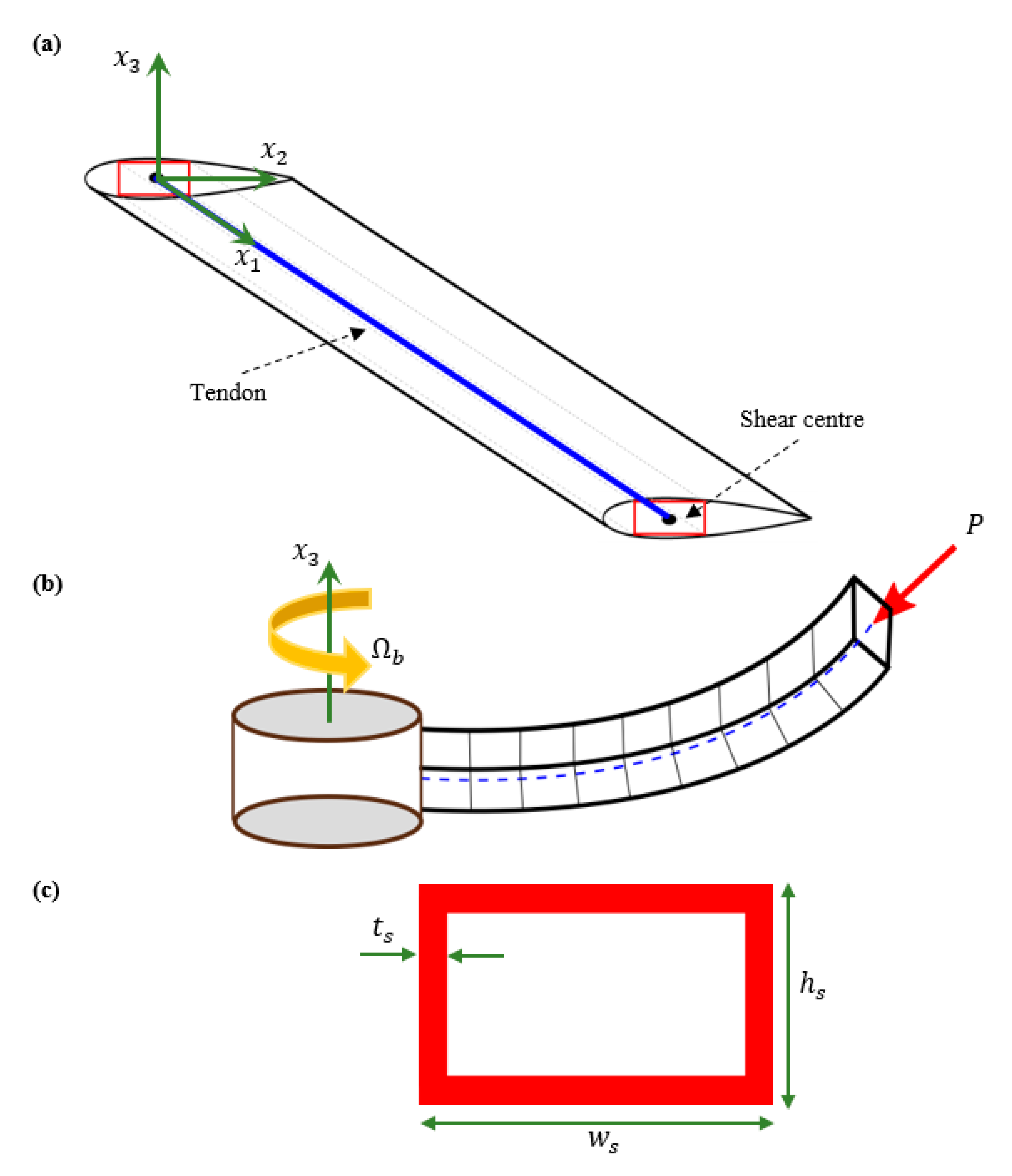
A composite blade rotating along an axis, shown in Figure 1, is considered. The blade length and rotating speed are denoted by L and respectively. It is assumed that the main load carrying part of the structure is the composite spar which is a rectangular box (Figure 1c). The spar box width, height, and thickness are denoted by , , and , respectively. It is assumed that a tendon is attached between the root and the tip of the blade and exactly lies on the elastic axis of the blade. This tendon is actuated using a proper mechanism at the root to provide the required compressive axial load. In this study, the tendon compressive force is simulated using a non-conservative axial force applied at the shear center of the blade tip (Figure 1b). It should be noted that the effect of tendon’s dynamics is not considered.
3. Formulation
Due to the high aspect ratio of the blade, it can be modelled using 1D beam equations. The nonlinear structural dynamics of the rotating composite blade are simulated using the geometrically exact fully intrinsic beam equations [20], as follows:
where and are the arc length () and temporal (t) derivatives respectively, and is the tilde operator (skew symmetric). Furthermore, the internal force, moment, linear velocity, and angular velocity are denoted by , , , and , respectively. is a vector storing all the external forces applied on the blade, which in this case is the non-conservative force. It must be noted that all the variables in Equation (1) are defined in the deformed reference frame. Furthermore, is a vector which is defined as follows:
Moreover, and are the generalized linear and angular momenta vectors which can be obtained using the linear and angular velocities as follows:
where and are the mass per unit length and the mass moment of inertial matrix, respectively, and is an identity matrix. In this study, the center of mass and reference axis are assumed to be coincident.
Furthermore, the internal force and moment vectors can be obtained using the strain measures (, ) using the following relationship:
where S is the stiffness matrix of the composite cross-section. It should be noted that, in this paper, the effect of extension–twist elastic coupling () on the dynamics of the blade is considered.
Finally, the resulting dynamic equations are discretized using a time–space scheme presented by Hodges [20]. To analyze the free vibration of the blade, first the nonlinear steady-state condition of the system is obtained by eliminating all the time derivatives terms from the discretized equations. Then, the equations are linearized about this nonlinear steady-state condition, and the eigenvalues of the linearized system are determined. Finally, the stability of the system is assessed by checking the real part of the eigenvalues. The blade enters into unstable region if the sign of the real part of any eigenvalue changes from negative to positive.
4. Numerical Results
In order to check the validity of the developed code, first the free vibration of a rotating blade with a composite rectangular cross-section is determined. Table 1 shows the comparison of the various frequencies of the blade with those determined by detailed FE analysis [24]. In this case, the outer width of the rectangular box is = 24.2 mm, the outer height is = 13.5 mm, and the thickness is = 0.762 mm. The rectangular box consists of 6 layers to make a symmetric layup ([15]6, [15/−15]6). It is clear that the obtained results are in very good agreement with the detailed FEM results reported in [24].
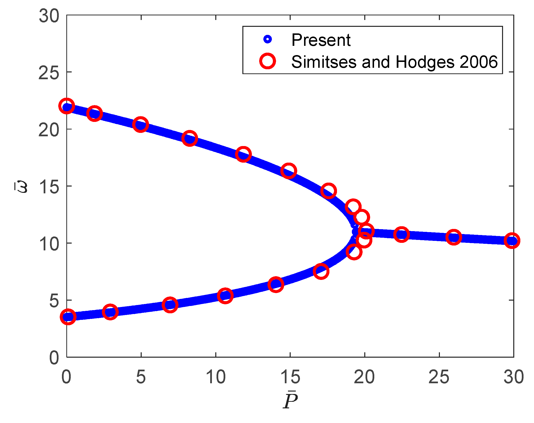
To validate the results for beams subjected to non-conservative forces, the frequency variation of an isotropic beam under a compressive axial non-conservative force is determined. The obtained results for a flapping condition are compared with those reported by Simitses and Hodges [25] and shown in Figure 2. It should be noted that all variables are presented in nondimensional form using the following equations
where is the axial compressive non-conservative force, and is the natural frequency.
The validation process (presented above) demonstrates that the developed formulation can predict accurate results for rotating composite blades subjected to non-conservative forces.
In what follows, the effect of a non-conservative axial compressive force on the rotating frequencies of composite blades is studied. As stressed earlier, the main load carrying member of the structure is assumed to be the composite spar-box which is made of AS4/3501 graphite/epoxy. The material and geometrical properties of the rectangular spar box cross-section are presented in Table 2. Furthermore, the blade characteristics are listed in Table 3.
In this study, the layup case, shown in Table 4, is considered. This layup is an antisymmetric box which creates an extension–twist coupling (). It should be noted that is the fiber angle for each layer.
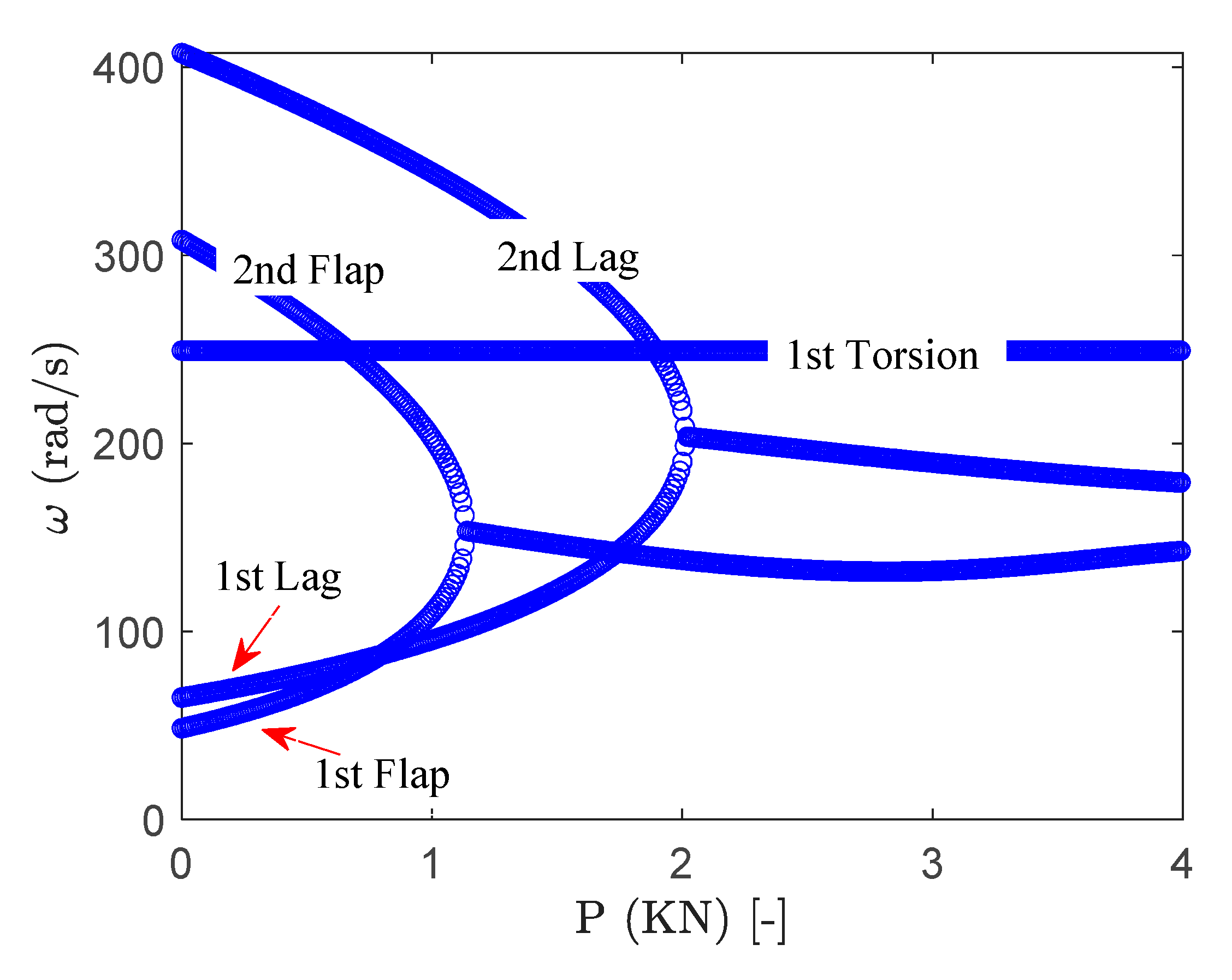
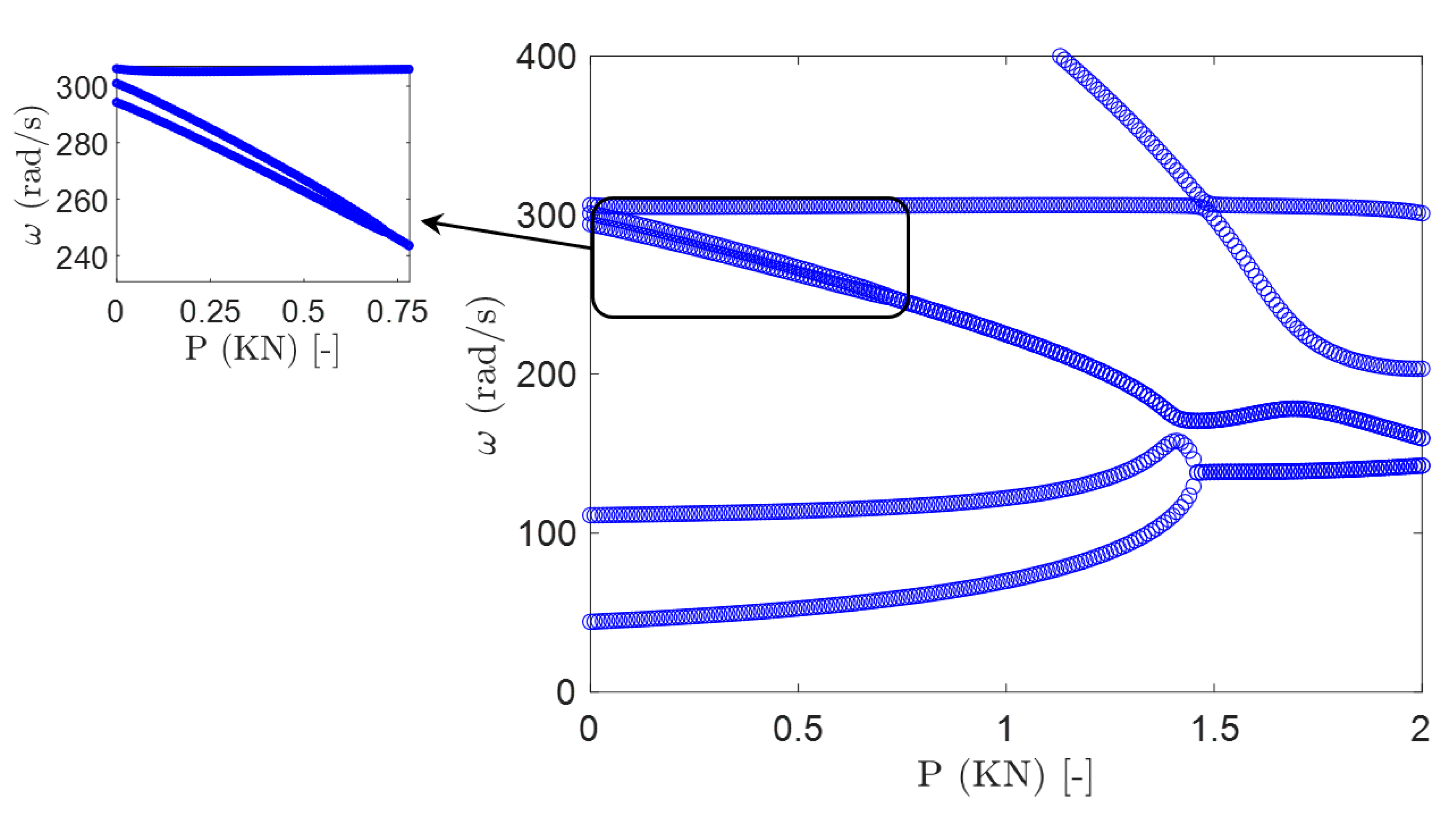
To determine the maximum compressive force that the blade can withstand without losing stability, the frequency variation of the stationary blade subjected to different values of compressive force is calculated and presented in Figure 3. The compressive non-conservative force affects all the frequencies except the torsional mode. By increasing the axial force, the first and second flap modes first coalesce until P = −1.14 kN at which the first instability occurs. The frequency of the first instability is . Furthermore, the first and second lag modes also coalesce to make the second instability point at P = −2.02 kN with the instability frequency being . Therefore, the amount of compressive force that can be applied to the isotropic blade without entering to the unstable domain should be less than |P| < 1.14 kN. It should be noted that from here on, the baseline critical compressive force and critical frequency are defined as = −1.14 kN and , respectively.
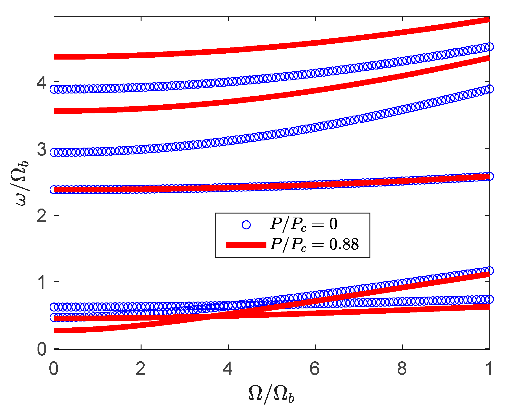
The effect of non-conservative axial force on the rotating frequencies of the isotropic blade () is determined and presented in Figure 4. The compressive non-conservative force affects all the rotating frequencies except the torsional mode. In addition, the compressive force changes the location at which the first and second modes (1st flap and 1st lag) cross each other. Furthermore, when the compressive force is applied to the blade tip, the lower frequencies are shifted down, while the higher frequencies are shifted up. It should be noted that higher frequency modes are affected more by the non-conservative force than the lower frequency modes. Therefore, it is clear that applying the proper amount of compressive force can tune or change the natural frequencies of the blade.
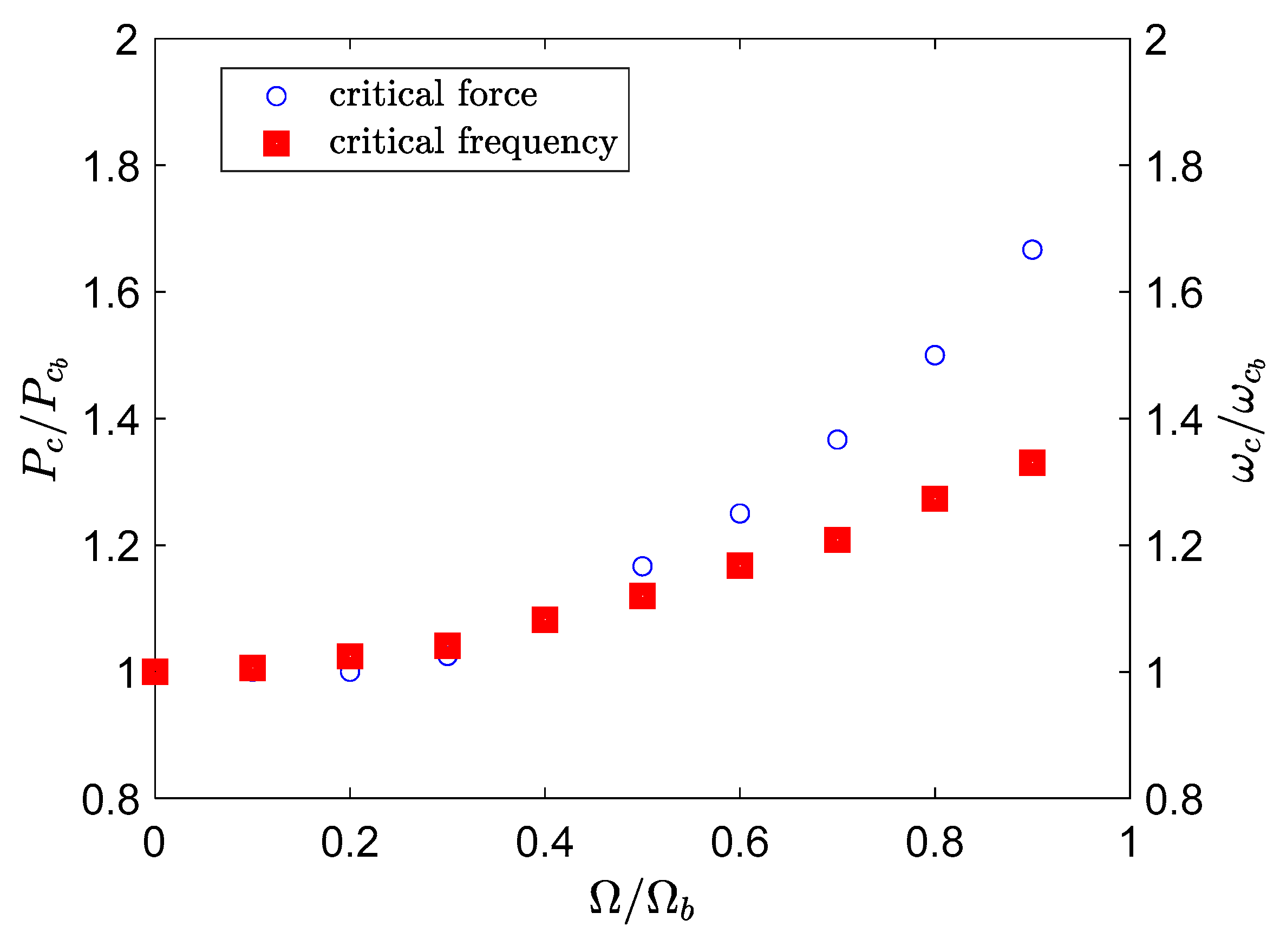
Figure 5 shows the effect of blade rotating speed on the critical compressive force and instability frequency at which the system enters into the instability region. It should be noted again that the index () refers to the baseline values at and . It is clear that for an isotropic blade, when the rotating speed increases, both the critical force and instability frequency increase. This is mainly due to the centrifugal force that acts opposite to the applied compressive force, and hence reduces its effect.
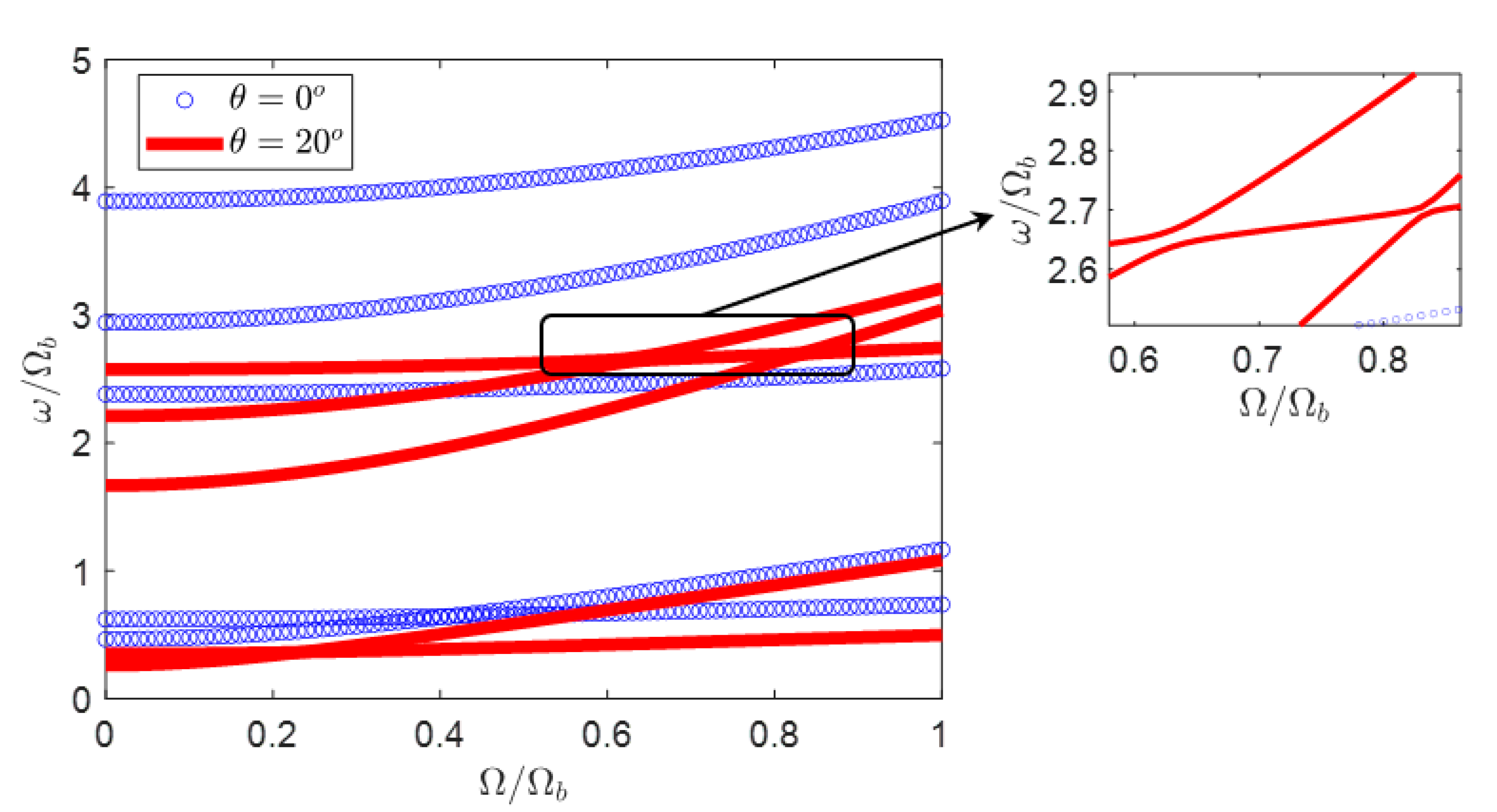
The effect of extension–twist coupling on the rotating frequencies of the composite blade is illustrated in Figure 6. It is clear that the extension–twist coupling affects the rotating frequencies of the blade. In this case, except the torsion mode, all other modes are shifted down when the ply angle changes to . It should be noted here that the third, fourth, and fifth modes veer away from each other first at , then at . Therefore, it is clear that the composite layup significantly affects the dynamics of the blade.
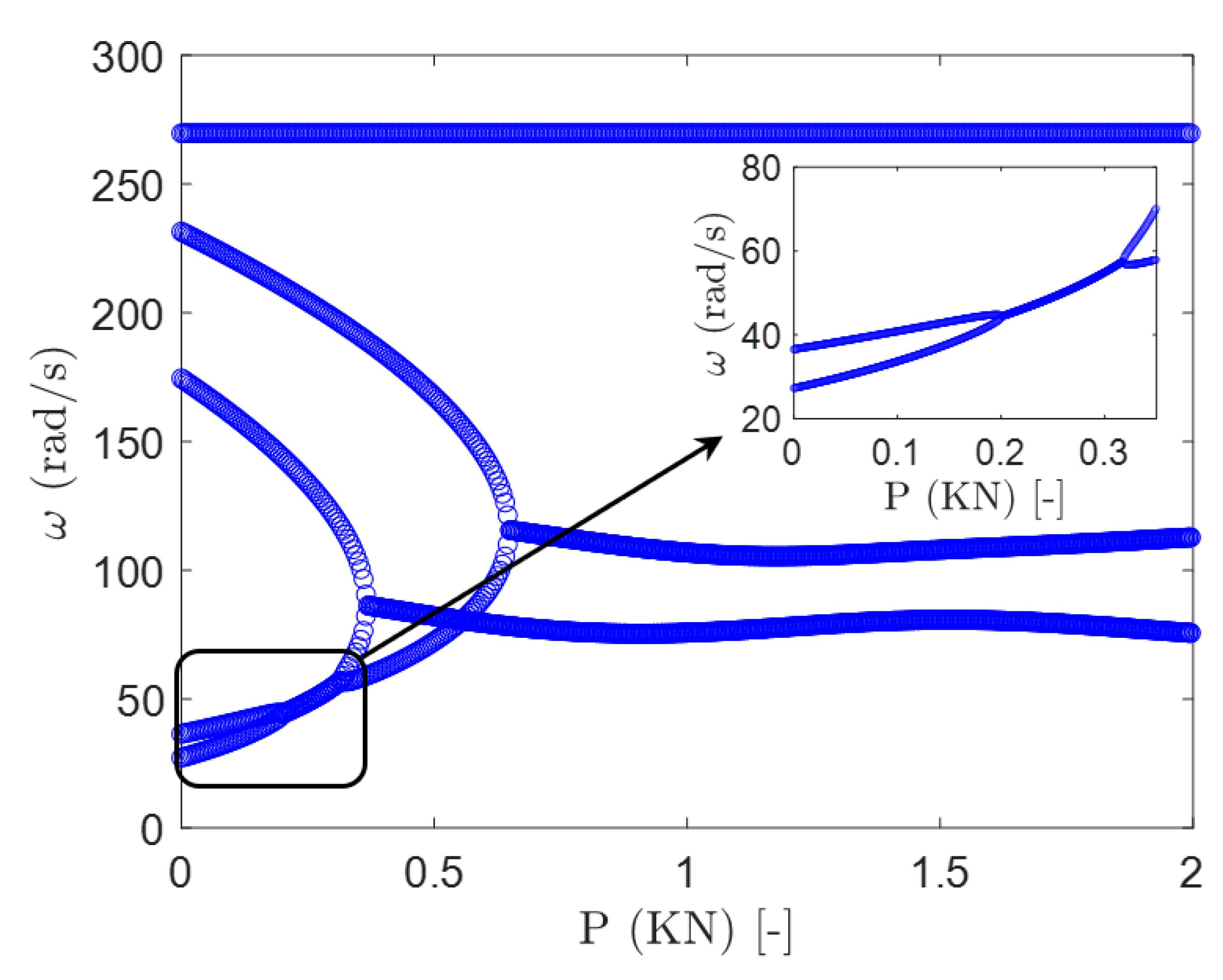
The effect of compressive force on the variation of stationary frequencies of the composite blade is determined and presented in Figure 7 for . In this case, an additional instability happens at low value of compressive force ( and ). The first instability is zoomed in to show that it is due to the coupling between the first and the second modes (1st flap and 1st lag) which was not the case for . Therefore, this highlights that the layup configuration significantly affects the stability of the blade when subjected to non-conservative compressive force, and hence significantly alters the effectives of this resonance avoidance concept.
The variation of the frequencies of the blade for two points before () and after () the first instability point (shown in Figure 7) is investigated next. Figure 8 shows the effect of rotating speed on the frequencies of the composite blade when the compressive force is . Although for the stationary blade this compressive force is in the stable region, however, at around rotating speed of , the rotating blade faces instability. Above , the rotating blade enters into the stable region again.
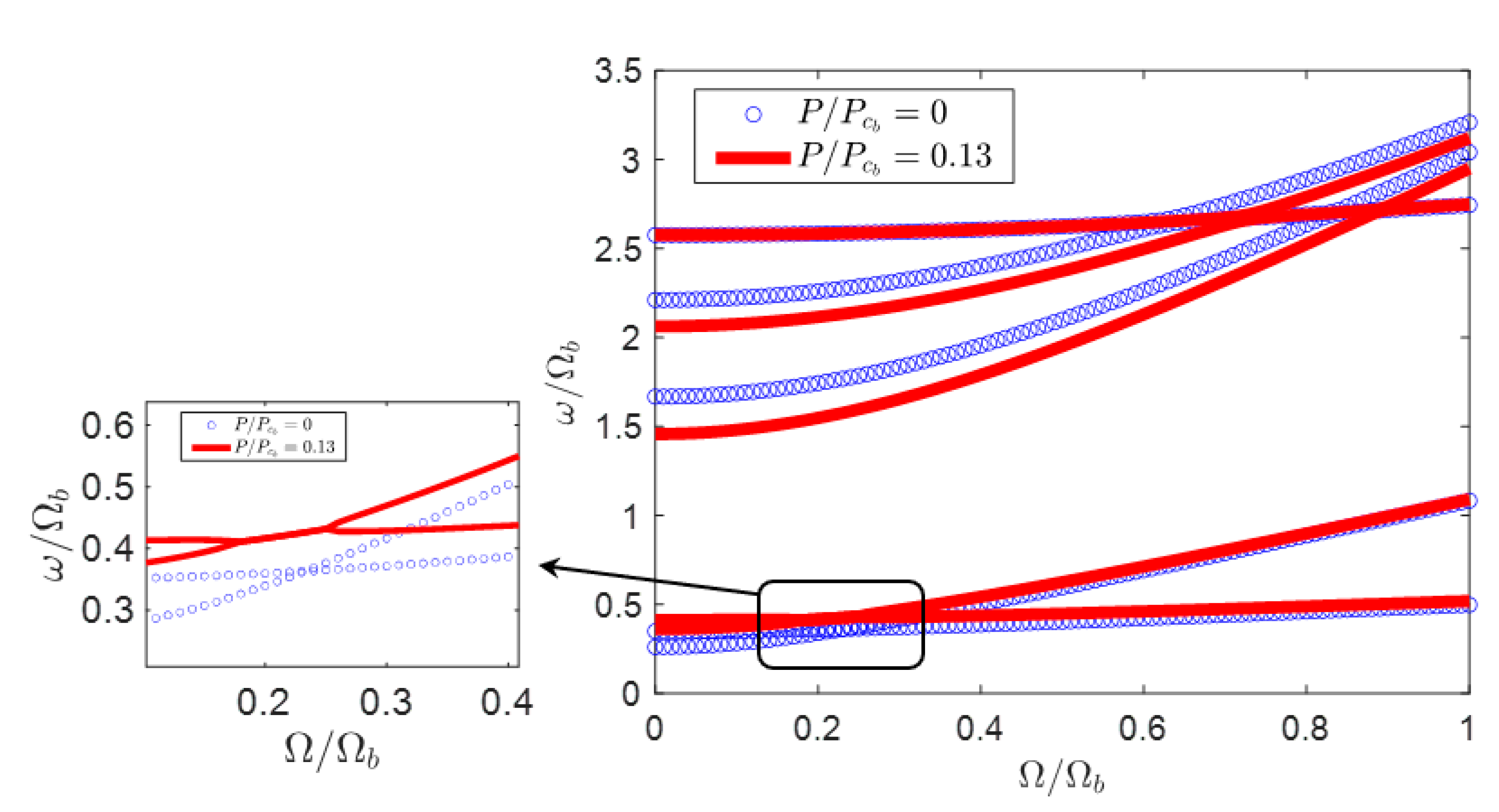
Furthermore, Figure 9 shows the effect of rotating speed on the frequencies of the composite blade for a point after the first instability region shown in Figure 7 (). In this case, the rotating blade is stable for all values of rotating speed. In this case, the first and second modes veer away from each other and this is the reason that the blade doesn’t suffer from instability. Therefore, it is clear that depending on the values of rotating speed, compressive force, and ply angle, the system could be stable or unstable when subjected to the compressive force. Similarly, the lower frequencies are shifted down, while the higher frequencies are shifted up. Therefore, the effect of ply angle on the stability of the blade when subjected to a non-conservative compressive force is considered next.
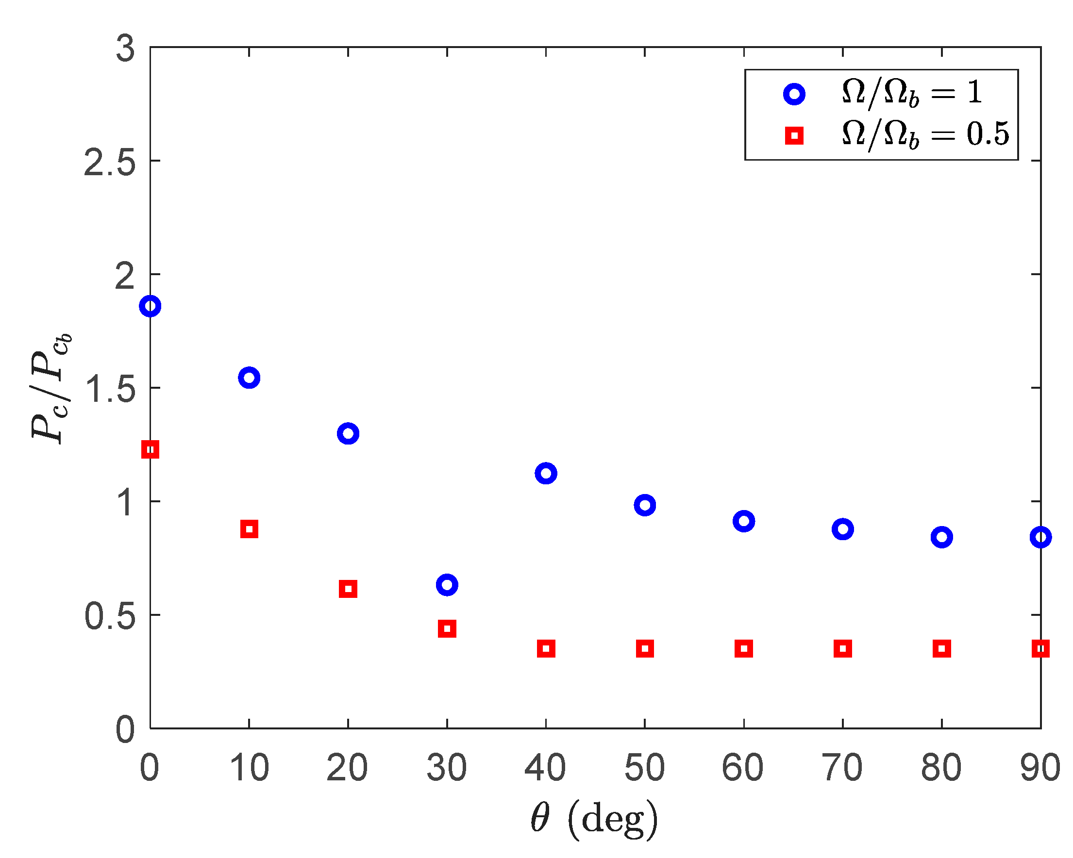
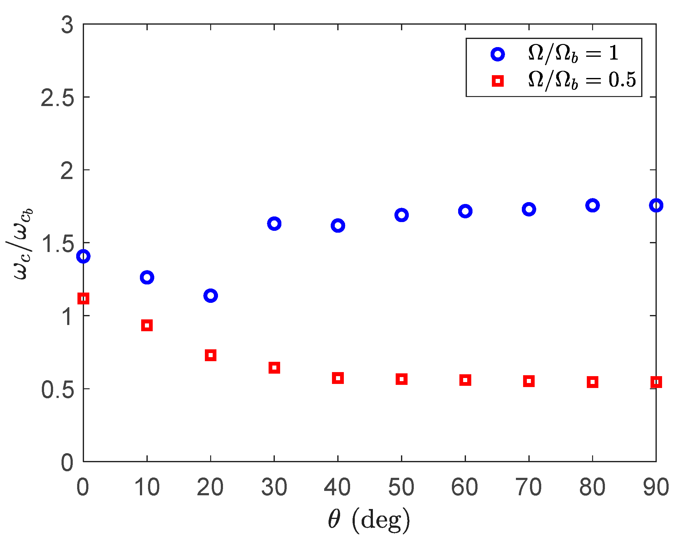
Figure 10 shows the variation of the critical compressive force and instability frequency of the rotating blade for various ply angles. By increasing the ply angle for both rotating speeds, the critical instability force decreases. However, a sudden reduction in the instability force is seen at a nondimensional speed of and at a ply angle of . Here, this ply angle works as a transition point at which the instability moves from the lower frequency modes to the higher frequency modes, and hence a jump is obvious in the instability frequency plot (Figure 11) at this ply angle. Therefore, it is clear that the ply angle has significant effect on choosing the right compressive force for tuning the natural frequencies of the blade. Figure 12 shows the effect of compressive force on the vibration of the blade at a ply angle and . It is clear that the instability moves to the higher modes and hence the jump in the instability frequency is apparent.
5. Conclusions
This paper assessed the performance of a resonance avoidance concept for composite blades. The concept used a tendon, attached to the tip of the blade, to apply a compressive force. This compressive force actively changed the dynamic behavior of the blade. The equivalent effect of the tendon was simulated using a non-conservative axial force applied to the blade tip. The composite blade had an antisymmetric layup configuration featuring the extension–twist coupling. The nonlinear dynamics of the composite blade were modelled using the exact beam formulation. The resulting differential equations were discretized using a time–space scheme, and the dynamics and the stability properties of the blade were determined using the eigenvalues of the linearized system. It was determined that by applying the compressive force to the composite blade, the frequencies as well as the location of frequency loci veering changed. The higher frequency modes were more sensitive to the compressive force. Furthermore, it was observed that the non-conservative compressive force could make the blade unstable depending on the rotational speed of the blade. In addition, the extension–twist elastic coupling introduced a new unstable region at low values of compressive force. This additional instability point strictly depended on the layup ply angle. In addition, it was shown that the ply angle of was the switching point at which the instability jumped from lower modes to higher modes. Finally, it was concluded that both blade rotating speed and layup angle affected the performance of the proposed resonance avoidance concept.
Author Contributions
Conceptualization, M.A.; methodology, M.A.; validation, M.A.; formal analysis, M.A.; investigation, M.A., M.B. and R.M.A.; writing—original draft preparation, M.A.; writing—review and editing, M.A., M.B. and R.M.A. All authors have read and agreed to the published version of the manuscript.
Funding
This research received no external funding.
Conflicts of Interest
The authors declare no conflict of interest.
References
- Dibble, R.; Ondra, V.; Titurus, B. Resonance avoidance for variable speed rotor blades using an applied compressive load. Aerosp. Sci. Technol. 2019, 88, 222–232. [Google Scholar] [CrossRef] [Green Version]
- Ondra, V.; Titurus, B. Free vibration analysis of a rotating pre-twisted beam subjected to tendon-induced axial loading. J. Sound Vib. 2019, 461, 114912. [Google Scholar] [CrossRef]
- Beck, M. Die Knicklast des einseitig eingespannten, tangential gedrückten Stabes [The buckling load of the cantilevered, tangentially compressed rod. Z. Für Angew. Math. Und Phys. Zamp 1952, 3, 225–228. [Google Scholar] [CrossRef]
- Hodges, D.H. Lateral-torsional flutter of a deep cantilever loaded by a lateral follower force at the tip. J. Sound Vib. 2001, 247, 175–183. [Google Scholar] [CrossRef] [Green Version]
- Kazemi-Lari, M.A.; Fazelzadeh, S.A. Flexural-torsional flutter analysis of a deep cantilever beam subjected to a partially distributed lateral force. Acta Mech. 2015, 226, 1379–1393. [Google Scholar] [CrossRef]
- Amoozgar, M.; Shahverdi, H. Dynamic Instability of Beams Under Tip Follower Forces Using Geometrically Exact, Fully Intrinsic Equations. Lat. Am. J. Solids Struct. 2016, 13, 3022–3038. [Google Scholar] [CrossRef] [Green Version]
- Fazelzadeh, S.A.; Tashakorian, M.; Ghavanloo, E.; Friswell, M.I.; Amoozgar, M. Nonconservative Stability Analysis of Columns with Various Loads and Boundary Conditions. AIAA J. 2019, 57, 4269–4277. [Google Scholar] [CrossRef]
- Abdullatif, M.; Mukherjee, R. Effect of intermediate support on critical stability of a cantilever with non-conservative loading: Some new results. J. Sound Vib. 2020, 485, 115564. [Google Scholar] [CrossRef]
- Friedmann, P.P. Rotary-Wing Aeroelasticity: Current Status and Future Trends. AIAA J. 2004, 42, 1953–1972. [Google Scholar] [CrossRef]
- Hodges, D.H. Review of composite rotor blade modeling. AIAA J. 1990, 28, 561–565. [Google Scholar] [CrossRef]
- Hong, C.H.; Chopra, I. Aeroelastic Stability Analysis of a Composite Rotor Blade. J. Am. Helicopter Soc. 1985, 30, 57–67. [Google Scholar] [CrossRef]
- McGee, O.G.; Chu, H.R. Three-Dimensional Vibration Analysis of Rotating Laminated Composite Blades. J. Eng. Gas Turbines Power 1994, 116, 663–671. [Google Scholar] [CrossRef]
- Song, O.; Librescu, L. Structural Modeling and Free Vibration Analysis of Rotating Composite Thin Walled Beams. J. Am. Helicopter Soc. 1997, 42, 358–369. [Google Scholar] [CrossRef]
- Oh, S.Y.; Librescu, L.; Song, O. Modelling and vibration of composite thin-walled rotating blades featuring extension-twist elastic coupling. Aeronaut. J. 2005, 109, 233–246. [Google Scholar] [CrossRef]
- Liu, T.R.; Ren, Y.S. Vibration of Wind Turbine Blade Modeled as Composite Thin-Walled Closed-Section Structure. Adv. Mater. Res. 2010, 129, 23–27. [Google Scholar] [CrossRef]
- Bekhoucha, F.; Rechak, S.; Duigou, L.; Cadou, J.M. Nonlinear forced vibrations of rotating anisotropic beams. Nonlinear Dyn. 2013, 74, 1281–1296. [Google Scholar] [CrossRef]
- Chen, J.; Li, Q.-S. Vibration characteristics of a rotating pre-twisted composite laminated blade. Compos. Struct. 2019, 208, 78–90. [Google Scholar] [CrossRef]
- Amoozgar, M.R.; Shaw, A.D.; Friswell, M.I. The effect of curved tips on the dynamics of composite rotor blades. Aerosp. Sci. Technol. 2020, 106, 106197. [Google Scholar] [CrossRef]
- Amoozgar, M.R.; Shahverdi, H. Aeroelastic Stability Analysis of Curved Composite Blades in Hover Using Fully Intrinsic Equations. Int. J. Aeronaut. Space Sci. 2019, 20, 653–663. [Google Scholar] [CrossRef]
- Hodges, D.H. Geometrically Exact, Intrinsic Theory for Dynamics of Curved and Twisted Anisotropic Beams. AIAA J. 2003, 41, 1131–1137. [Google Scholar] [CrossRef]
- Amoozgar, M.R.; Shahverdi, H. Analysis of nonlinear fully intrinsic equations of geometrically exact beams using generalized differential quadrature method. Acta Mech. 2016, 227, 1265–1277. [Google Scholar] [CrossRef]
- Sotoudeh, Z.; Hodges, D.H. Structural Dynamics Analysis of Rotating Blades Using Fully Intrinsic Equations, Part I: Formulation and Verification of Single-Load-Path Configurations. J. Am. Helicopter Soc. 2013, 58, 1–9. [Google Scholar] [CrossRef]
- Mardanpour, P.; Izadpanahi, E.; Rastkar, S.; Fazelzadeh, S.A.; Hodges, D.H. Geometrically Exact, Fully Intrinsic Analysis of Pre-Twisted Beams Under Distributed Follower Forces. AIAA J. 2018, 56, 836–848. [Google Scholar] [CrossRef]
- Smith, E.C.; Chopra, I. Aeroelastic Response, Loads, and Stability of a Composite Rotor in Forward Flight. AIAA J. 1993, 31, 1265–1273. [Google Scholar] [CrossRef]
- Simitses, G.J.; Hodges, D.H. Preface. In Fundamentals of Structural Stability; Butterworth-Heinemann: Burlington, NJ, USA, 2006. [Google Scholar]
Figure 1.
Schematic of the rotating composite blade subjected to the tendon induced axial force: (a) undeformed state, (b) tendon induced compressive force, (c) composite spar-box section.
Figure 1.
Schematic of the rotating composite blade subjected to the tendon induced axial force: (a) undeformed state, (b) tendon induced compressive force, (c) composite spar-box section.

Figure 2.
The variation of the flap modes of a stationary isotropic beam subjected to an axial non-conservative force.
Figure 2.
The variation of the flap modes of a stationary isotropic beam subjected to an axial non-conservative force.

Figure 3.
The variation of the first five frequencies of the stationary composite blade subjected to compressive force for .
Figure 3.
The variation of the first five frequencies of the stationary composite blade subjected to compressive force for .

Figure 4.
The effect of axial force on the rotating frequencies of the composite blade for .

Figure 5.
The effect of rotating speed on the critical compressive force and instability frequency for .
Figure 5.
The effect of rotating speed on the critical compressive force and instability frequency for .

Figure 6.
The effect of ply angle on the rotating frequencies of the composite beam with antisymmetric layup and for .
Figure 6.
The effect of ply angle on the rotating frequencies of the composite beam with antisymmetric layup and for .

Figure 7.
The effect of compressive force on the stationary frequencies of the composite blade with antisymmetric layup and for and .
Figure 7.
The effect of compressive force on the stationary frequencies of the composite blade with antisymmetric layup and for and .

Figure 8.
The effect of compressive force on the frequencies of the blade before the first instability point () and for .
Figure 8.
The effect of compressive force on the frequencies of the blade before the first instability point () and for .

Figure 9.
The effect of compressive force on the frequencies of the blade after the first instability point () and for .
Figure 9.
The effect of compressive force on the frequencies of the blade after the first instability point () and for .
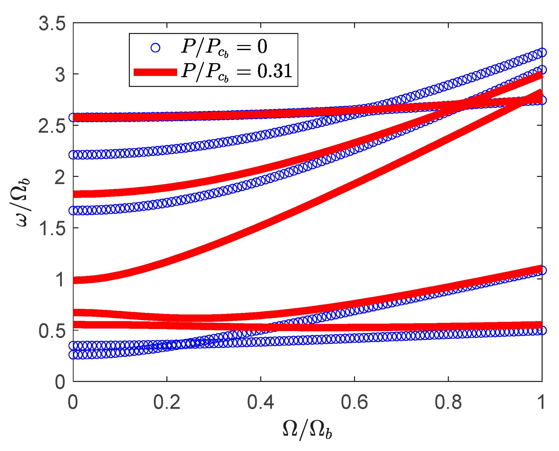
Figure 10.
The effect ply angle on the critical instability force.

Figure 11.
The effect ply angle on the critical instability frequency.

Figure 12.
The effect of compressive force on the rotating frequencies of the composite blade with antisymmetric layup and for and .
Figure 12.
The effect of compressive force on the rotating frequencies of the composite blade with antisymmetric layup and for and .


Table 1.
The rotating frequencies of the composite rectangular box blade with symmetric layup ().
| Mode | Present | Smith and Chopra [24] | Differences (%) |
|---|---|---|---|
| 1st Flap (Hz) | 35.4 | 36.0 | −1.7 |
| 2nd Flap (Hz) | 195.5 | 197.3 | −0.9 |
| 1st Lag (Hz) | 56.7 | 57.1 | −0.7 |
| 2nd Lag (Hz) | 351.1 | 349.3 | 0.5 |
| 1st Torsion (Hz) | 713.7 | 714.9 | −0.2 |
Table 2.
The geometrical and material properties of the composite rectangular spar-box.
| Property | Value |
|---|---|
| E11 (GPa) | 142.0 |
| E22 = E33 (GPa) | 9.8 |
| G12 = G13 (GPa) | 6.0 |
| G23 (GPa) | 3.77 |
| ν12 = ν13 | 0.3 |
| ν23 | 0.34 |
| ρ (kg/m3) | 1445 |
| 12.804 | |
| 8.944 | |
| 0.804 | |
| Number of layers | 6 |
Table 3.
The blade characteristics.
| Property | Value |
|---|---|
| L (m) | 0.9615 |
| (kg/m) | 0.343 |
| (kg.m) | 2.062 |
| (rpm) | 1000 |
Table 4.
The antisymmetric composite layup of the box spar.
| Layup | Top | Bottom | Left | Right |
|---|---|---|---|---|
| Antisymmetric | []6 | [−]6 | []6 | [−]6 |
Publisher’s Note: MDPI stays neutral with regard to jurisdictional claims in published maps and institutional affiliations. |
© 2020 by the authors. Licensee MDPI, Basel, Switzerland. This article is an open access article distributed under the terms and conditions of the Creative Commons Attribution (CC BY) license (http://creativecommons.org/licenses/by/4.0/).
Share and Cite
MDPI and ACS Style
Amoozgar, M.; Bodaghi, M.; Ajaj, R.M. The Effect of Non-Conservative Compressive Force on the Vibration of Rotating Composite Blades. Vibration 2020, 3, 478-490. https://0-doi-org.brum.beds.ac.uk/10.3390/vibration3040030
AMA Style
Amoozgar M, Bodaghi M, Ajaj RM. The Effect of Non-Conservative Compressive Force on the Vibration of Rotating Composite Blades. Vibration. 2020; 3(4):478-490. https://0-doi-org.brum.beds.ac.uk/10.3390/vibration3040030
Chicago/Turabian StyleAmoozgar, Mohammadreza, Mahdi Bodaghi, and Rafic M. Ajaj. 2020. "The Effect of Non-Conservative Compressive Force on the Vibration of Rotating Composite Blades" Vibration 3, no. 4: 478-490. https://0-doi-org.brum.beds.ac.uk/10.3390/vibration3040030