1. Introduction
1.1. Research Goals
Rotating equipment plays an important role for many applications in the process industry because its functionality is crucial for the productivity and safety of plants and, thus, business success. The components of each piece of equipment must be highly reliable in order to reduce downtime costs. Even more challenging is the avoidance of unplanned plant shutdowns resulting from equipment failure, especially failure of single key components. One such key component is the mechanical seal often used as shaft sealing in process machinery applications such as in agitator vessel systems [
1].
There are several useful measurement techniques, whereas the following are the most promising possibilities:
Currently, condition monitoring and the early detection of damage to rotating equipment are primarily based on classical vibration analysis according to DIN ISO 10816 [
2]. This standard prescribes a measuring range of 10–1000 Hz, within which the RMS (root mean square) value of the vibration velocity is determined. For this scalar value, specifications are given regarding the maximum acceptable values. In addition, there are also analysis methods, such as spectral and envelope analysis, in which vibrations of up to approximately 15 kHz are typically included. This enables the drawing of conclusions on untypical mechanical behavior by correlating these conspicuous frequencies with the dominant rotation frequency (e.g., rolling element bearing frequencies). This shows the limitations of classical vibration analysis, which relies on distinct kinematics and comparably high rotational speeds or undesirable long acquisition times.
In some applications, thermal imaging is used to detect damages and faulty behavior. For the presented case of mechanical seals in a heated environment, the technique cannot be employed reliably, as not only parts are impacted by friction heat up, but also their surroundings. For precise measurements in this context, another technique may be preferred.
Acoustic measurements can be used for vibration measurement. Microphones pick up sound vibrations that are emitted by the machinery. It is possible to measure high frequencies, but inevitable noise from the environment has to be filtered out. This leads to an approach that measures the relevant vibrations more closely to their source.
When microscopic phenomena are dominant and vibration emissions are significantly determined by material characteristics that are also independent of the shaft rotational speed [
3], high-frequency vibrations are the result. One promising approach for detecting and analyzing such phenomena is known as the acoustic emission technique (AET). However, the costs and the necessary resource intensity of this application are higher than other approaches [
4].
The goal of this paper is to present an approach of using the AET for the monitoring of mechanical seals in process industry.
1.2. Basics of Mechanical Seals
Mechanical seals are widely used in process engineering [
1]. They serve as a barrier to prevent the escape of fluid from inside a vessel to the surrounding environment by obstructing the passageway between the machine housing and the rotating shaft. In most cases within the process industry, this represents a safety-relevant feature [
5]. Moreover, premature mechanical seal failure can lead to high follow-up costs and irreparable damage to the machine or plant or even endanger people and the environment [
1]. Fault-free operation of the mechanical seal must be ensured as unplanned shutdowns usually result in higher maintenance costs than regular maintenance downtimes. Appropriate monitoring methods provide continuous information on the condition of the mechanical seal. Thus, unplanned maintenance activities can be prevented and an extension of the time intervals between regular services can be achieved [
5].
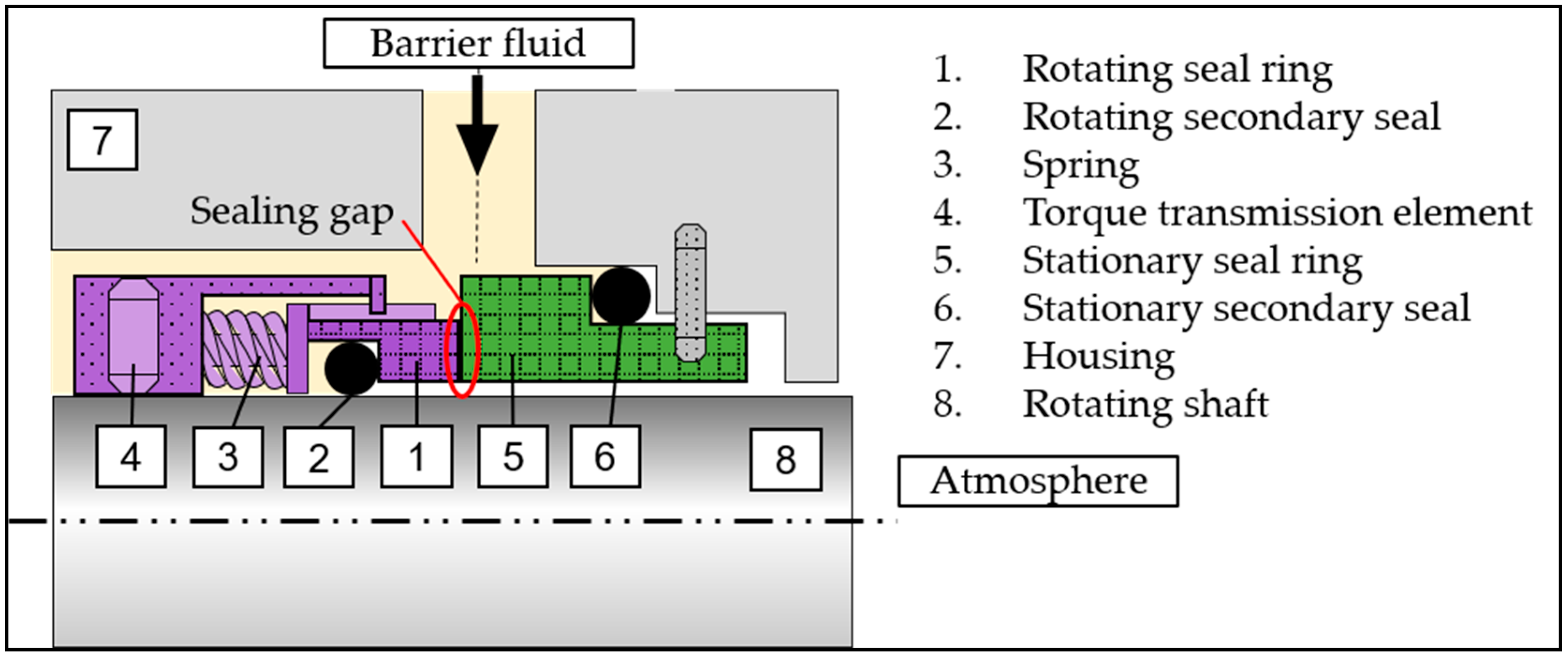
Mechanical seals generally consist of two major components: a rotating seal ring attached to the shaft and a stationary seal ring inserted into the seal housing. Both rings are aligned to each other so that their end faces meet. The resulting hollow cylinder space between the two rings is called the sealing gap. To fulfill the function of the mechanical seals, the following additional elements are required: secondary seals, springs and components for transmitting the torque of the shaft. The use of one or two pairs of seal rings in a mechanical seal depends on its application. These types of seals are called single or double-acting mechanical seals respectively. In
Figure 1, the two main components are highlighted by color and the additional elements are schematically depicted.
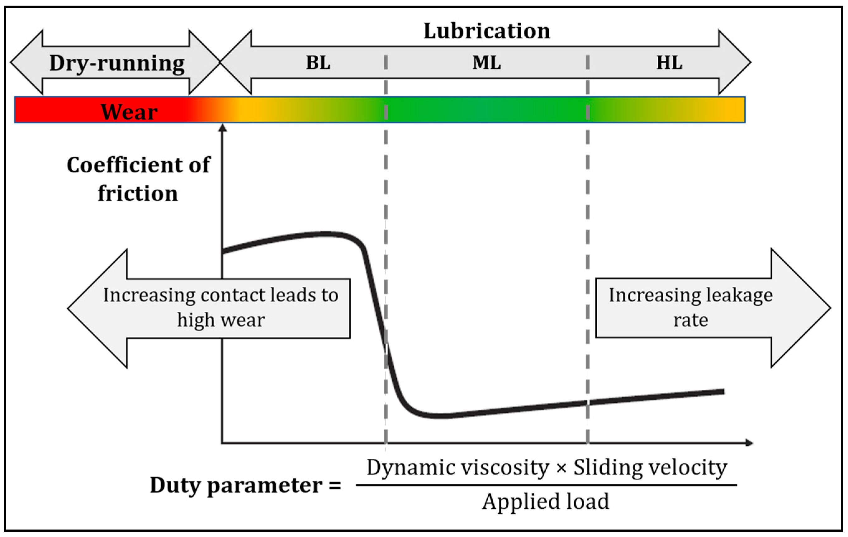
One common version is the liquid-buffered mechanical seal, which entails a barrier fluid system as another important component. This dissipates the heat generated by frictional processes within the sealing gap and lubricates the faces of the seal rings to hinder them from touching each other. Thus, the barrier fluid functions as a coolant and lubricant of the mechanical seal. The circulation of the barrier fluid through the mechanical seal is normally performed by a circulation pump or by the thermosyphon principle. The latter is defined as the natural circulation of a liquid in a closed circuit due to temperature-driven density differences. It is physically impossible to ensure operation without leakage, as the barrier fluid provides the barrier needed to keep the seal rings separated and to prevent the escape of the fluid to be sealed to the surroundings. Thus, the leakage rate must always be kept as low as possible. To ensure that the permissible leakage rate is as low as possible, the seal ring faces are subjected to a lapping process and the sealing gap is designed to be very small by choosing the pretensioning of both rings with respect to the rotational speed, seal ring materials and seal ring diameter. Mechanical seals also comprise a drain hole in the housing, where an inadmissible increase of the leakage rate can be determined by visually detecting the presence of barrier fluid there. The frictional behavior inside the sealing gap is depicted in
Figure 2 as a function of the relative velocity between the seal rings (sliding velocity), the applied load and the dynamic viscosity of the barrier-fluid. For liquid-buffered mechanical seals, three lubrication states can occur: boundary (BL), mixed (ML) or hydrodynamic (HL) lubrication. The progress between these states is represented by the Stribeck curve [
6]. The lubricating film thickness in ML corresponds approximately to the average roughness of the two friction partners and represents the best compromise in terms of wear and leakage. However, operation in ML depends significantly on the operation conditions. If high loads or low speeds are present, the seal ring surfaces are not completely separated and high wear is expected due to the increased interaction between the asperities of the surfaces at a microscopic level. On the other hand, if low loads and high speeds occur, the lubricating film thickness exceeds the surface roughness and the leakage rate increases significantly. The transition from BL to an unlubricated condition (also called dry running) is marked by a drastic increase in wear rate [
6].
If the operation conditions do not match the specific conditions for which the mechanical seal was intended, the seal may experience partial damage or total failure. For example, the mechanical seal experiences unstable conditions at start-up and shutdown as well as when problems in the barrier fluid system occur. For this reason, one of the most common causes of damage to mechanical seals is inappropriate lubrication. Towsyfyan [
7] gathered the results of a survey about the reasons for mechanical seal failures in centrifugal pumps and found that dry running (in almost 25% of all cases) and abrasive wear (in approximately 16% of all cases) were the main factors that lead to failure. This information coincides with the long-term data collected by practical experience within the BASF SE community in the area of process machinery and maintenance, specifically in the Rotating Equipment department.
Without a change of the system’s operating conditions, violent fluctuations of the leakage rate are indications of malfunctions in the performance of or even damage to the mechanical seal [
8]. The presence of an inadmissibly high leakage rate may indicate a complete failure of the mechanical seals and therefore it must be replaced. Most mechanical seal damage is due to inadmissible friction between the seal rings. Given that the quality of the lubrication in the sealing gap is associated with a higher generation of friction between the seal rings, unfavorable lubrication conditions can lead to seal damage [
7]. These friction mechanisms can be associated with acoustic emissions (AE) [
9].
The mechanical seal itself is a tribological system, in which the energy released is mainly converted into heat and (only to a lesser extent) into AE [
9]. The characteristic frequency of the excited vibrations in a tribological system is determined only by the natural frequency of the integral system and not by the vibration characteristic of each subcomponent. The intensity of the AE emitted due to the friction process is influenced by the composition of the materials, the roughness of the surface and the speed of the relative motion. Nonetheless, the frequency of the excited vibrations remains dependent on the rigidity of the tribological system [
4]. When observed on a microscopic level, the collisions between the surface irregularities of the seal ring faces, which are spread over the entire contact surface, excite the natural frequencies of the individual asperities. The frequency ranges excited here depend on the properties of the individual asperities, such as height, width, cross-sectional area and modulus of elasticity of the material [
9]. As hard material particles can cause abrasive wear on the surface of softer seal ring materials and thus lead to the formation of microcracks and spalling on the surface of both seal rings [
10], potential abrasive particles inside the sealing gap must be conveyed away by the barrier fluid flow and filtered in the barrier fluid system. This helps to avoid additional damage to the sealing components caused by particle erosion.
1.3. Preceding Research in Wear Detection Relating to Mechanical Seals
Zou and Green [
11] were able to successfully detect unwanted contact between two seal ring faces in real time using eddy current proximity probes. Anderson et al. [
12] suggested a monitoring system that could be applied retroactively to field operation to detect the contact of two seal ring faces and measure its severity. This method was based on the detection of actively generated ultrasonic transverse waves reflected from the faces of the seal rings.
Miettinen and Siekkinen [
13] were able to detect a change in the RMS value of the AE signals between normal running, leakage and dry running conditions of a double-acting mechanical seal applied on a centrifugal pump. Mba et al. [
14] successfully assessed the applicability of the AE measurement to detect the onset and duration of contact between the seal rings. Moreover, Towsyfyan [
7] studied the response of the AE signals to changes in the lubrication states due to changes in the operation conditions. They reported the possibility of identifying the states using a combination of RMS and kurtosis values of the AE signals. In addition, they suggested that the direct interaction of asperities generates high-frequency AE signals (between 50 and 300 kHz). Furthermore, the influence of the rotational speed of the shaft and the barrier fluid system pressures on the vibrational behavior of mechanical seals was investigated. They found that, at low rotational speeds, AE amplitude values are higher with increasing seal pressures due to greater friction between the seal ring faces. Hase et al. [
10] summarized the result of different literature into an overview of the frequency spectra of wear-emitted AE. Significant differences between the investigations appear to be dependent on the utilized type of sensor, measuring system and the experimental conditions. According to Hase et al. [
10], a dependence between the distribution of the AE frequencies and the type of wear can be found. Almeida et al. [
15] analyzed the damage process of a ceramic matrix composite during fatigue and found that the AE measurements provide information about the severity, type and onset of the damage. Ferrer et al. [
16] investigated the AE that originated due to slip events resulting from contact between the surface asperities. Chung et al. [
17] investigated a method based on AE measurements for monitoring the wear caused by hard particles that slide between two surfaces. The frequency spectra show excitation of the frequencies between about 100 and 400 kHz with a large peak at 200 kHz. According to Chung et al. [
17], noise emissions result from rolling and from the collision of the abrasive particles between the sliding surfaces. Ramadan et al. [
18] characterized the frequency spectra of the AE generated by crack growth and propagation and breakage in high-strength steel. The growth and propagation of cracks were characterized by a frequency range of 100 to 600 kHz with a large peak at 200 kHz.
Based on the above-mentioned studies, this work describes a novel approach for monitoring failure modes due to inadequate friction processes inside mechanical seals using the AET. For this purpose, typical failure condition modes (namely dry running, insertion of abrasive particles into the buffer fluid flow and a total failure in the buffer fluid system) of a double-acting mechanical seal mounted on a test agitator vessel system were induced. The emitted AE were simultaneously recorded and analyzed. It was possible to detect unfavorable friction processes due to the aforementioned failure modes at an early stage. Indicators for premature failure of the utilized mechanical seal were found.
2. Acoustic Emission Technique
The acoustic emission technique (AET) is a non-destructive testing method for the measurement and assessment of high-frequency vibrations in the range of 0.2 MHz to 2 MHz. Scruby et al. [
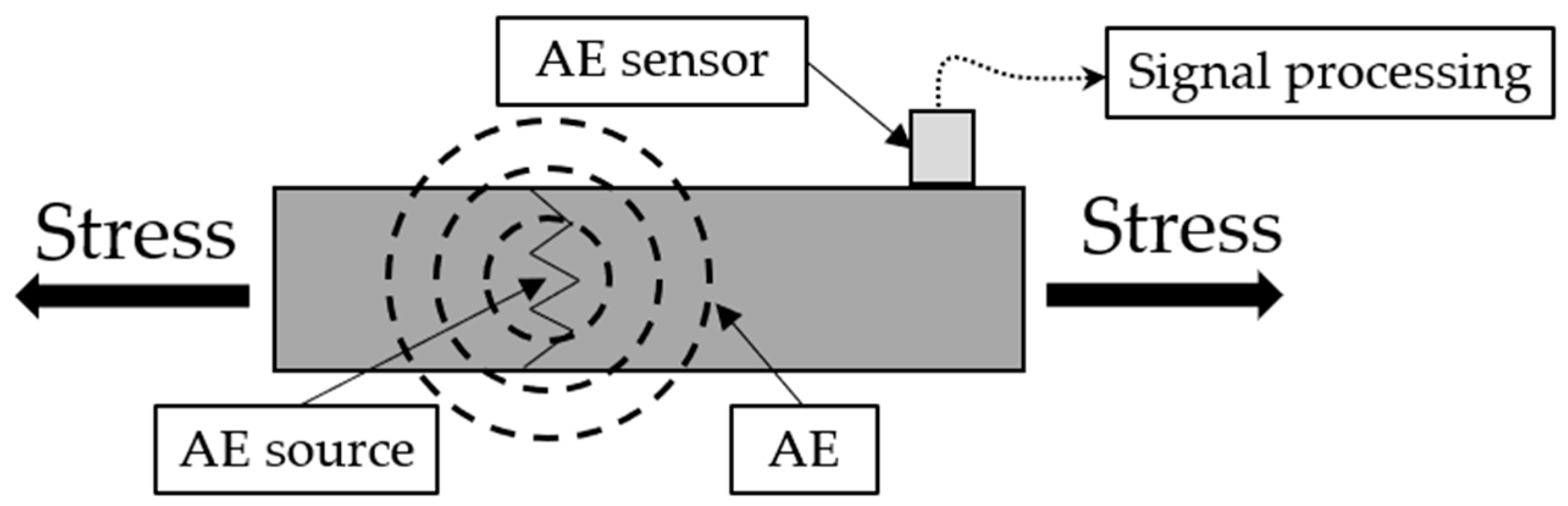
19] define acoustic emission (AE) as a “spontaneous release of a structure-borne transient wave in a solid as a consequence of a sudden local stress change”. This local change in the stress energy can occur as a result of damage, such as cracks or plastic deformation. Any physical event that causes an AE is addressed as an AE event, whereas an AE source is defined as the spatial element from which one or more AE events arise. The transient wave propagates through the solid and on the surface in all directions depending only on the component geometry and material characteristics. An AE exceeding a certain amount of energy can be detected by an AE sensor whose measuring method is based on the piezoelectric effect. A detected transient wave is usually referred to as a hit. A single AE event may result in multiple hits [
19]. The formation, propagation and detection of AE are illustrated in
Figure 3. In this work, the AE activity is defined as the occurrence of AE events exceeding the minimum detectable amount of energy specified by the utilized AE sensor. Thus, a high AE activity means that many hits have been detected in a short amount of time.
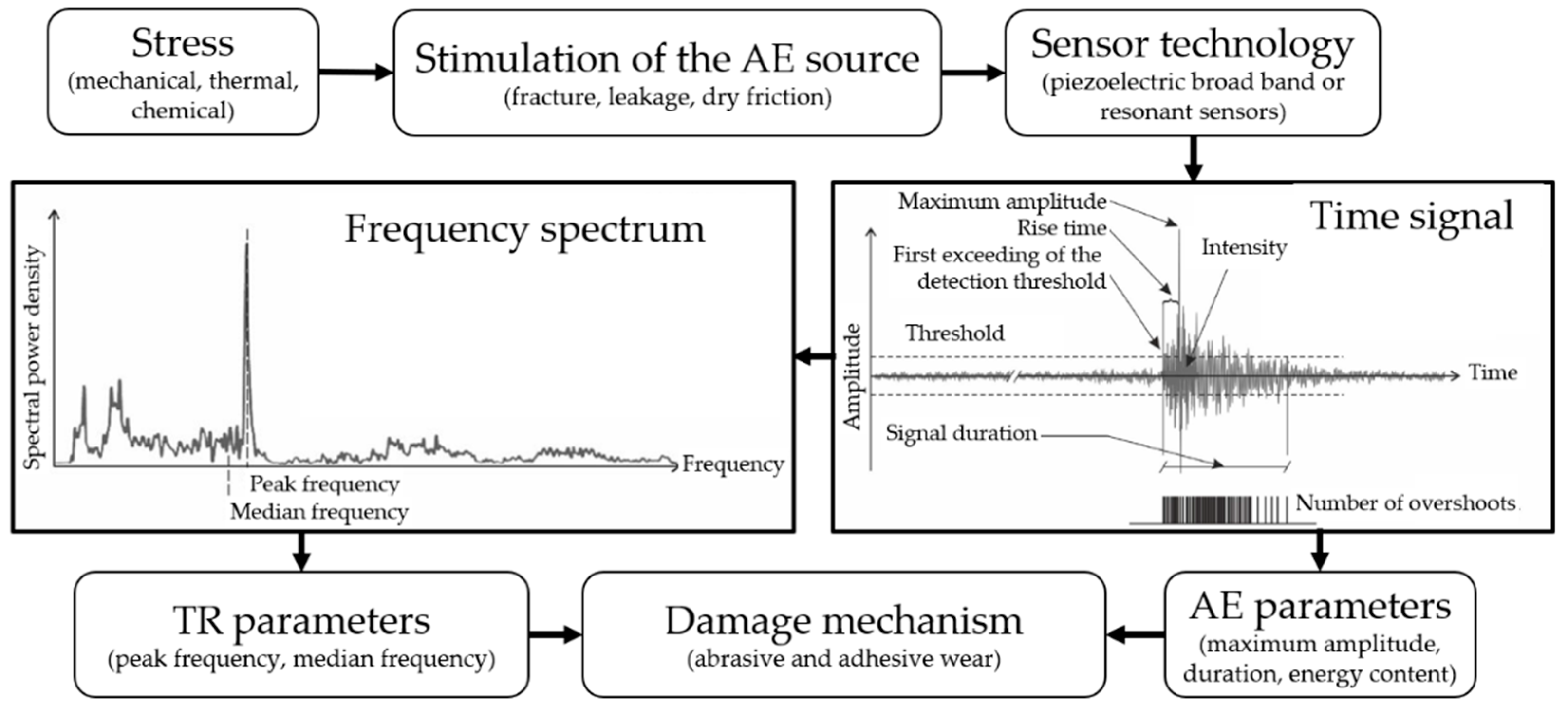
To prevent the recording of disturbing background noises, a threshold filter is typically used whereby only AE with higher amplitudes are recorded. The threshold can be user-adjustable, fixed or automatically adjustable. The recording of the signal starts when the amplitude of a hit exceeds the threshold level and ends when it falls below the threshold again. The waveform is then used to determine the so-called AE parameters (see
Figure 4), such as the maximum amplitude or the hit duration. Utilizing a fast Fourier transformation (FFT), the spectrum of the signal can be determined, which can then be used to create additional parameters including the peak or median frequency; these are known as transient parameters (TR parameters) [
20]. In non-destructive testing, different damage generation mechanisms can be distinguished using these parameter sets. The amplitudes of the AE signals are given in decibel AE (dB
AE) with a reference voltage of 1 µV [
21].
Figure 4 shows a summary of the signal processing of AE measurements.
3. Experimental Setup
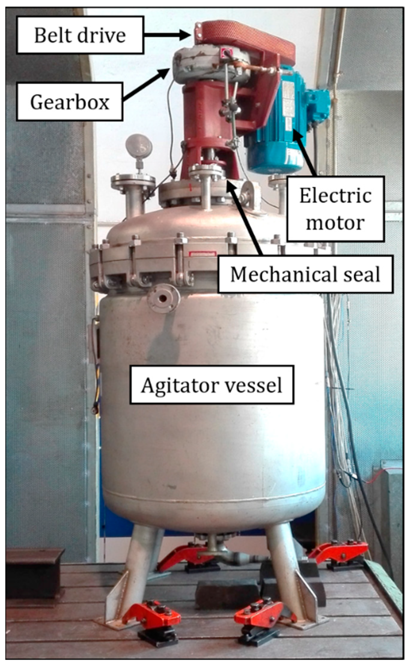
The test rig consists of an agitator vessel system with a double-acting liquid-buffered mechanical seal. The agitator vessel is equipped with a tubular baffle. To vary the shaft speed, the electric motor is controlled by a variable frequency drive with a sinusoidal filter and shielded cables to attenuate noise interference. The components of the agitator vessel system and their specifications are summarized in
Table 1.
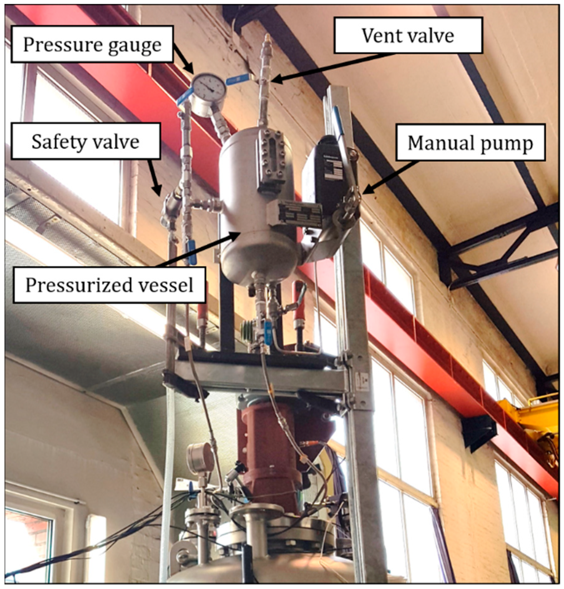
Furthermore, the mechanical seal of the agitator vessel system was equipped with a thermosyphon-type barrier fluid system. Additionally, a pressurized vessel with variable pressure between 0 and 10 bar was installed. White mineral oil and demineralized water were used as barrier fluids.
Figure 5 shows the agitator vessel system assembly and
Figure 6 the barrier fluid system.
Two double-acting mechanical seals in back-to-back arrangement with a hard/soft seal ring pairing (designation: Cartex-DN/60-00) from EagleBurgmann were tested consecutively in this work. The soft seal ring material consists of resin-impregnated carbon graphite while a non-pressure sintered silicon carbide was used for the hard seal ring material. The temperature was measured in a borehole located in the mechanical seal’s housing near the upper seal ring pair.
The emitted AE were measured, processed and visualized with the acoustic emission device AMSY-6 (Acoustic Measurement System 6th generation) from Vallen Systeme GmbH. The AMSY-6 is a well-accepted measuring system in the field of non-destructive testing and material science and is frequently used in scientific publications [
15,
16,
22].
In this work, the “continuous mode” of the AMSY-6 was used. First, a threshold is defined based on the results of previous experiments. If this threshold is exceeded, the recording of the time signal begins and ends after a previously selected measurement period. Consecutive measurements are recorded as long as the threshold is being exceeded. In this work, the measurement period was set to 1000 µs, as this corresponds approximately to the duration of the longer expected burst signals. From each one of these measurements, some parameters of the time signal and frequency spectra are derived and stored in the AMSY-6. In the present work, the maximum amplitude value and the frequency spectrum of the measured AE were considered.
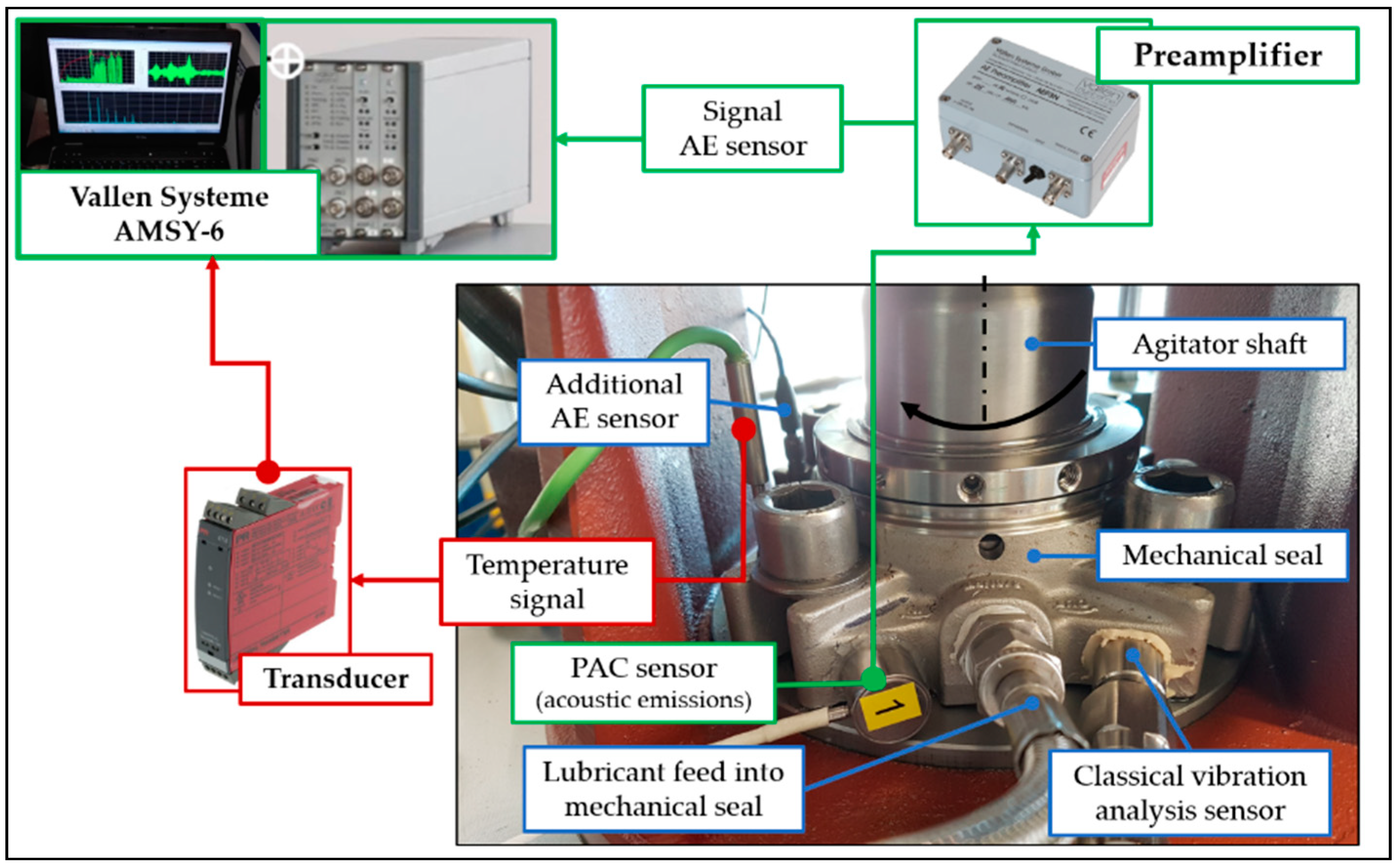
The WD sensor from the physical acoustics corporation (PAC) with an operating frequency range from 125 kHz to 1 MHz was employed in a radial position to obtain the AE signals. These were amplified by 34 dB
AE with the AEP3N preamplifier from Vallen Systeme GmbH. The sampling frequency was 2.5 MHz and the maximum number of samples per set was 262.144. The Vallen VisualAE software from Vallen Systeme GmbH was used to visualize the data. The Korasilon Paste M-S 2-200 from Kurt Obermeier GmbH (Bad Berleburg, Germany) was used as a coupling agent for the sensor. For test rig monitoring purposes, one additional AE sensor and one sensor from the classical vibration analyses, which can be seen in
Figure 7. AMSY-6 measuring system setup on the double-acting mechanical seal, were also installed. The experimental setup is shown in
Figure 7.
4. Experimental Procedure
In order to develop indicators for the early detection of increased leakage in mechanical seals, various fault condition modes were induced in the barrier fluid system to investigate their influence on the seals’ vibrational behavior. These are typical fault conditions that can occur during the operation of an agitator vessel system. The agitator speed was set to 615 rpm in all experiments. For the measurement of the AE signals in the AMSY-6, the threshold was adjusted manually for each experiment in accordance with previously collected experimental data. For the first two measurements, the selected threshold was 60 dBAE and for the last two measurements it was 45 dBAE. The experimental procedure was as follows:
Measurement 1: Operation under normal conditions of the barrier fluid system with white oil serving as barrier fluid. No fault condition modes were induced.
Measurement 2: Dry-running operation of the mechanical seal. In order to investigate the vibrational behavior of the mechanical seal without lubrication, the barrier fluid system was emptied. Thus, the seal operated without barrier fluid.
Measurement 3: Abrasive particles. As high abrasive friction is associated with the onset of cracks, microscopic corundum particles were added to the barrier fluid system in order to investigate their influence on the seals’ vibrations. The agglomeration of the abrasive particles inside the barrier fluid system prevents them arriving at the mechanical seal. To avoid this, demineralized water was used as the barrier fluid because these particles tend to agglomerate in high-viscosity liquids rather than in low-viscosity ones.
Measurement 4: Cooling failure. High temperatures in the sealing gap can lead to a partial or total evaporation of the barrier fluid, thus causing seal operation under BL conditions. As BL is associated with high wear, a cooling failure in the mechanical seal could lead to a high increase in the leakage rate. After reaching a steady-state temperature in the mechanical seal, the supply of barrier fluid in the seal was completely interrupted. The previously introduced corundum particles were not removed to ensure an accelerated wear process.
5. Results
5.1. Normal Operation
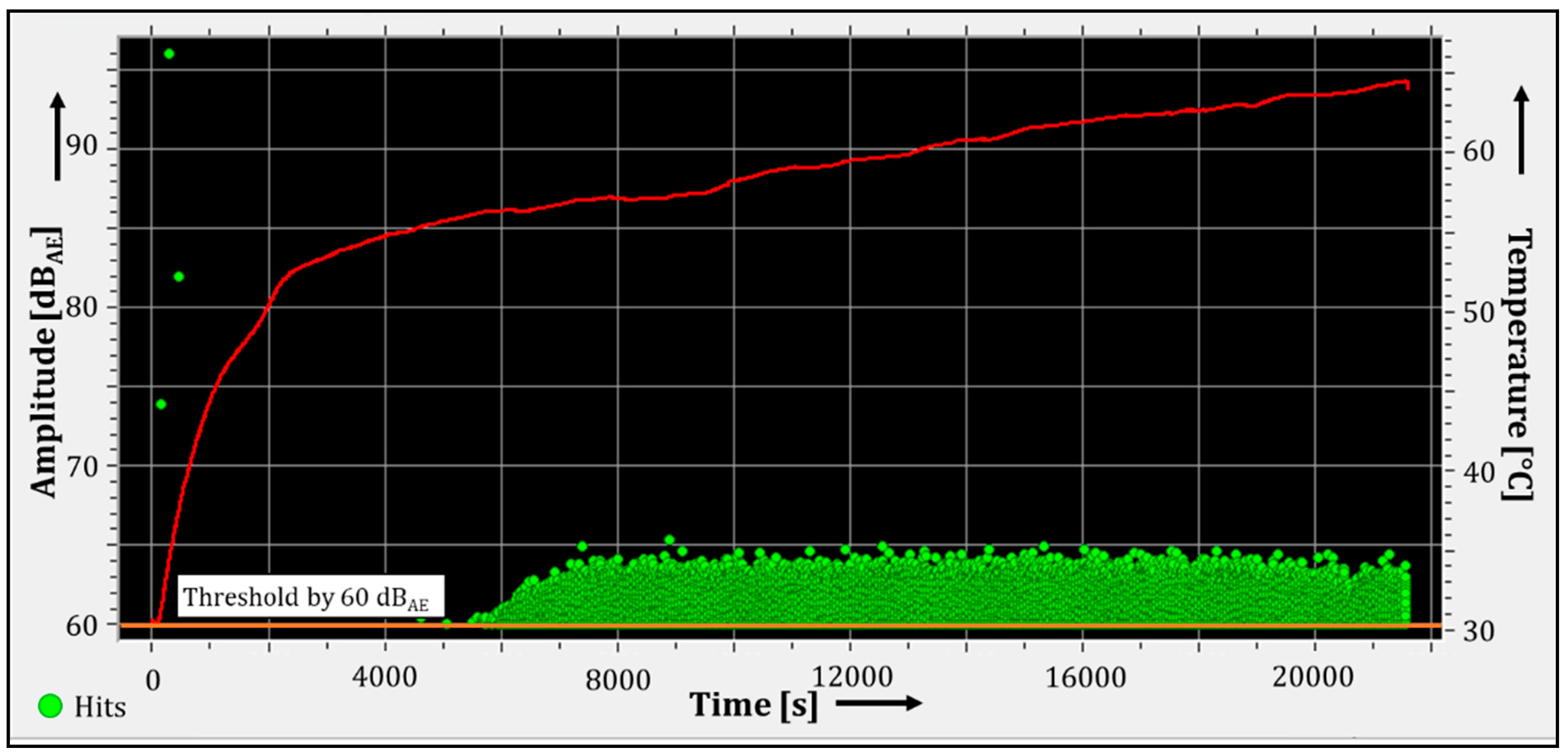
The results of the first experiment with normal operating conditions of the barrier fluid system are represented in
Figure 8. Whenever the amplitude of the signal exceeds the previously set threshold, a time signal with a duration of 1000 µs is measured and then its frequency spectrum is calculated. The highest amplitude during the 1000 µs timespan of each signal is represented in
Figure 8 with a green dot. This is called a hit. The
y-axis on the left-hand side is associated with the amplitudes of the hits. In this case, a band with a higher distribution density of hits can be distinguished after 6000 s with amplitude values under 65 dB
AE. With the Vallen VisualAE software, the associated information of each hit (e.g., its respective time signal and frequency spectrum) can be visualized. The red line describes the temperature progression over time of the mechanical seal’s housing and is represented in the right
y-axis.
5.2. Dry-Running Operation
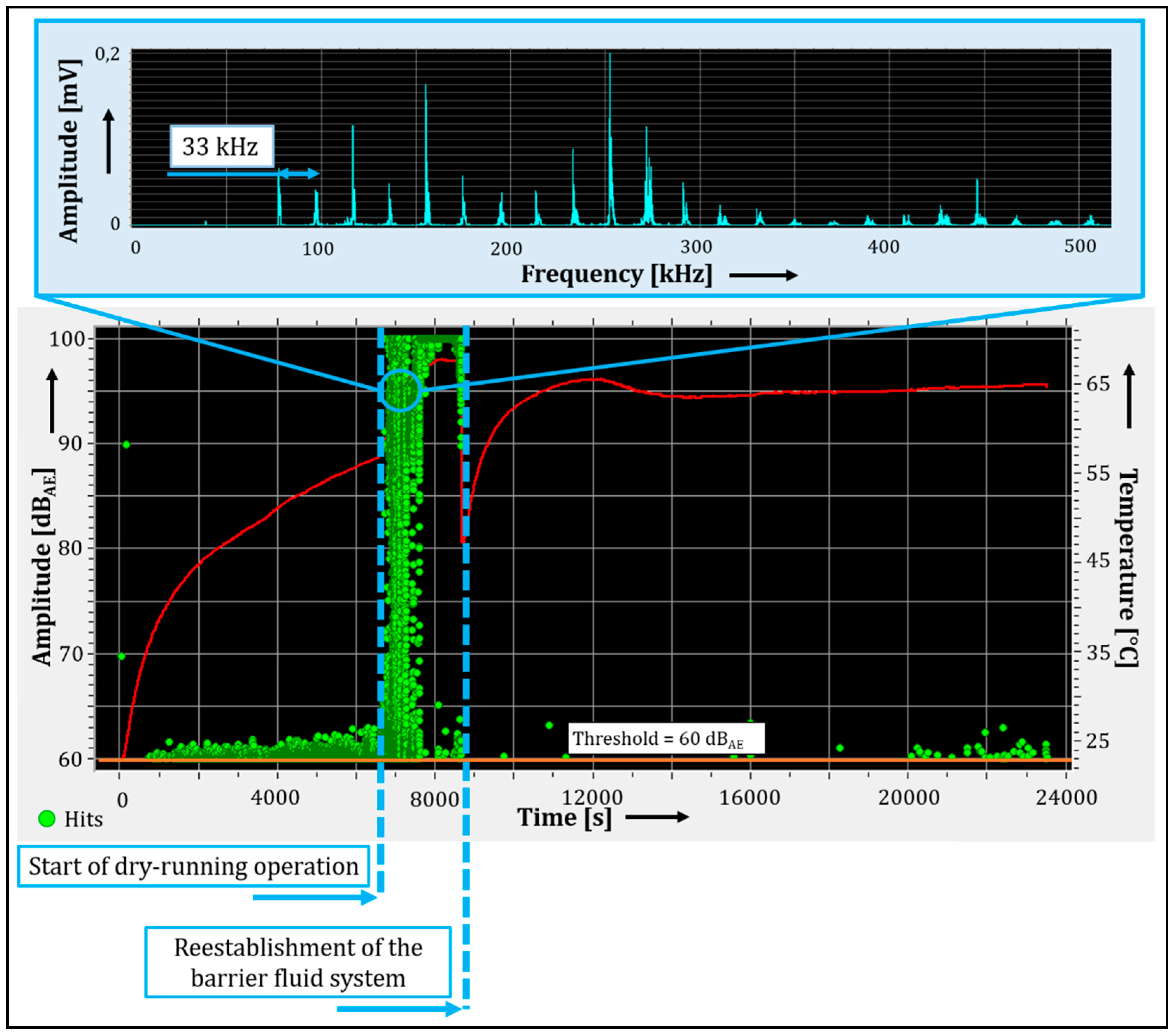
The barrier fluid system was emptied to initiate dry-running operation. The results are shown in
Figure 9. During the first 6000 s of the experiment, no noticeable change in AE was apparent although no barrier fluid was present in the pressurized vessel of the barrier fluid system. This is probably due to the remaining barrier fluid in the sealing gap, most likely between the asperities of the seal ring faces. Subsequently, an increase of the hits exceeding the threshold can be observed. This can be assigned as the real start of dry-running operation. The calculated frequency spectra of the hits recorded during dry running showed the presence of the harmonics of a 33 kHz frequency. This behavior was identical for each measurement. During dry-running operation, there was a strong increase in AE intensity, causing the system to exceed its measurement range. As a result, the maximum amplitudes could not be detected. However, a level increase of at least 35 dB
AE compared to normal operation was found, which corresponds to an increase of the linear amplitude by a factor of 56.
After approximately 30 min of dry-running operation, the measurement was paused and the mechanical seal was filled with barrier fluid to verify whether the leakage rate had increased. When the seal barrier fluid system was reestablished, the vibrational behavior of the seal showed no deviations in comparison to normal operation. After 11 days of repeating the same procedure, a higher leakage rate was detected and the seal was replaced.
5.3. Abrasive Particles
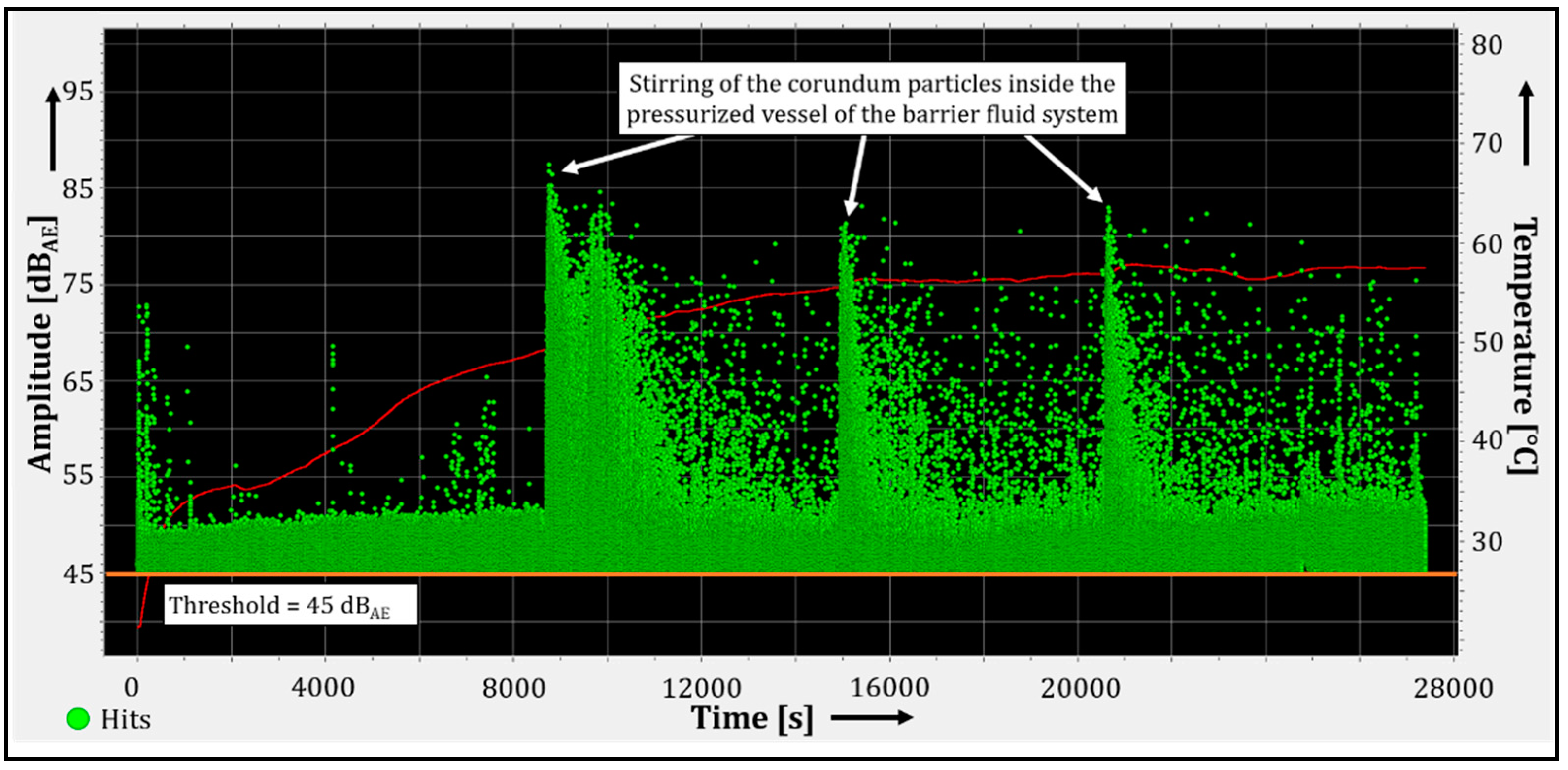
As addressed in the Introduction, abrasive particles can cause wear in the sealing gap, especially on the surface of the seal ring made of carbon graphite. This can lead to the formation of microcracks on the surface of the carbon graphite and spalling on the surface of both sliding materials. Here, the continuous flow of the barrier fluid through the mechanical seal plays an important role, since this is the only way to guarantee the supply of particles to the sealing gap and, consequently, induce abrasive wear. The friction heat generated in the sealing gap is transferred to the barrier fluid, which activates the thermosyphon principle in the barrier fluid system. Due to their sedimentation tendency, the corundum particles were occasionally manually stirred in the pressurized vessel of the barrier fluid system during the experiments in order to bring the sedimented particles back in motion. A lower threshold was set to allow a better understanding of the vibrational behavior of the mechanical seal under this fault condition mode.
The results are shown in
Figure 10. A more unstable vibrational behavior can be observed, as the measured hits exhibited amplitude values between 45 and 87.5 dB
AE, the latter being the maximum amplitude detected during the experiment. A band with a higher distribution density of hits can be distinguished between 45 and approximately 50 dB
AE; this can be defined as the background noise of the measurement. The hits with amplitudes greater than 50 dB
AE are relevant to a further discussion of the AE activity at a later part of this paper. For this reason, a digital filter was later used.
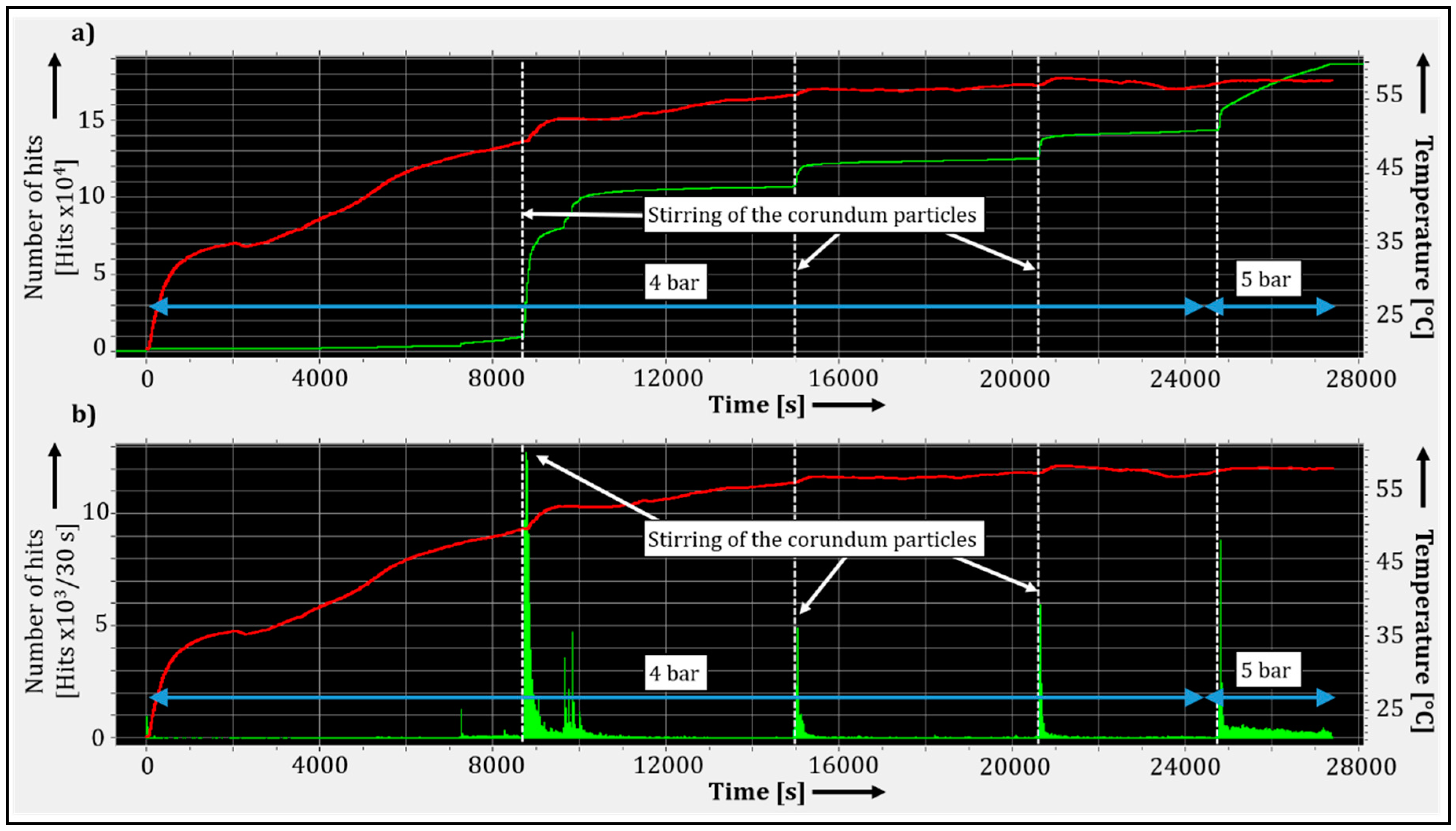
The upper diagram in
Figure 11 shows the accumulation of the previously detected hits, which is represented by the green line corresponding to the left
y-axis. The height of the green bars in the lower diagram represents the number of hits that occurred over the course of the previous 30 s. In both diagrams, the red line corresponds to the temperature measurement. Furthermore, all hits considered in
Figure 11 had amplitude values greater than 50 dB
AE.
By comparing
Figure 10 and the diagrams of
Figure 11, the change in AE activity over time becomes obvious. Peak-like AE activity increases were detected briefly after the abrasive particles were stirred in the pressurized vessel of the barrier fluid system. These instant accumulations of hits were followed by a noticeable rise of the temperature of the mechanical seal housing. Due to proximity, this correlates with a greater generation of heat inside the sealing gap. During the last 3000 s of the measurement, the number of hits with amplitude values greater than 50 dB
AE increased due to the increase by 1 bar of the pressure inside the barrier fluid system. This corroborates the findings of Towsyfyan [
7], who found that for low speeds (below 1.200 rpm) the increase in pressure inside the mechanical seal leads to an increase in the amplitudes of the detected AE.
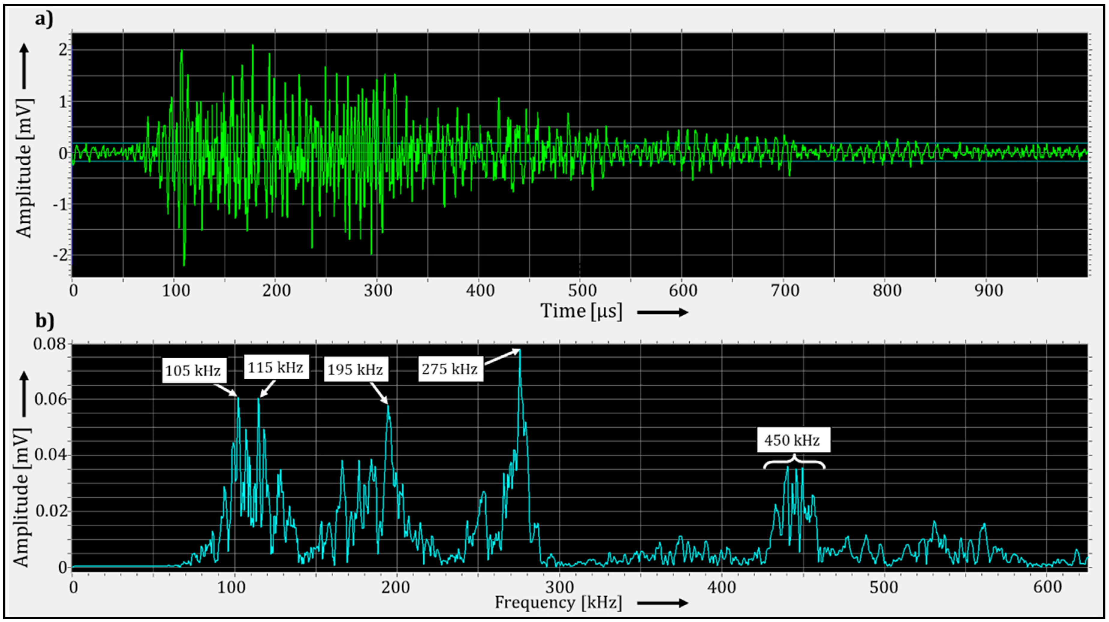
A hit was randomly selected from the hits with a greater amplitude than 50 dB
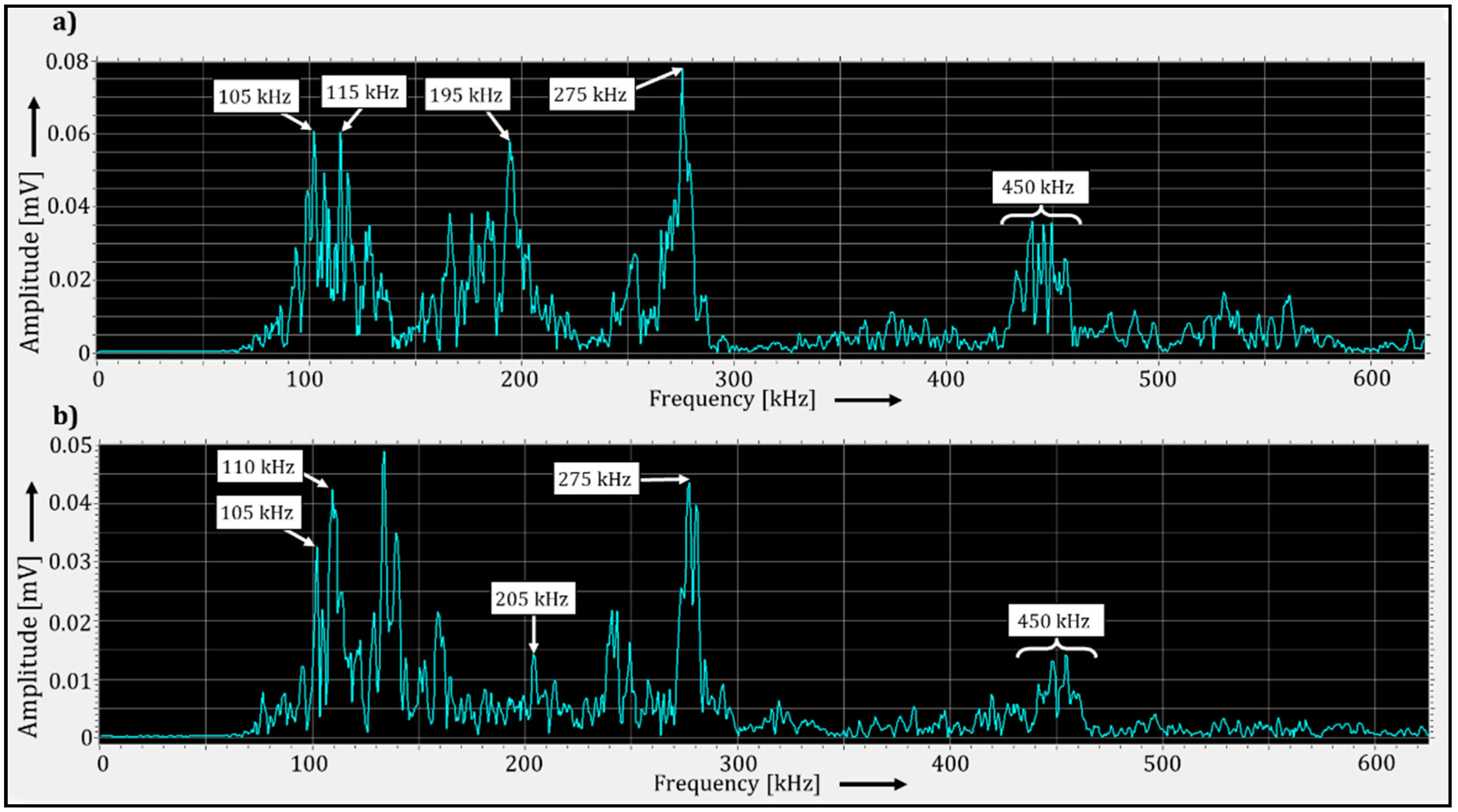
AE and that occurred during the abrupt increases of AE activity. Its time signal and frequency spectrum are shown in
Figure 12. The frequency spectrum exhibits a general excitation of the frequencies between 100 and 625 kHz. In particular, high amplitude peaks occurred at approximately 105, 115, 195, 275 and 450 kHz. This frequency pattern was found in other hits that occurred during the abrupt increases of AE activity.
5.4. Cooling Failure
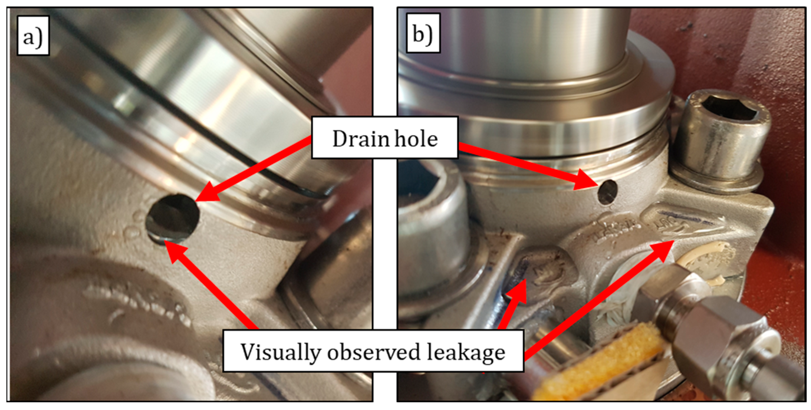
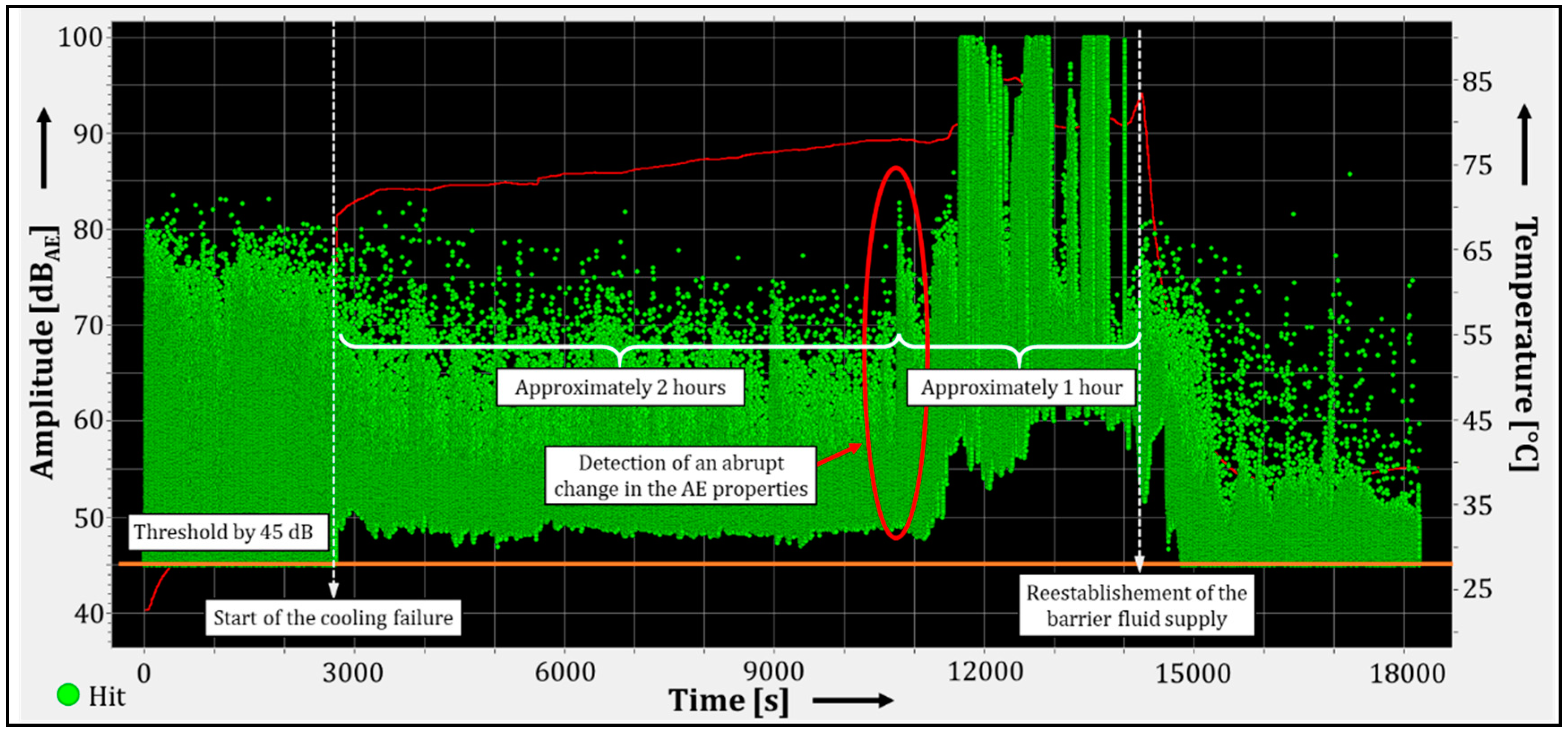
Almost 3000 s after the start of this experiment, a cooling failure was induced by removing the barrier fluid supply from the mechanical seal. After approximately 3 h without effective cooling of the seal, a leakage was detected by visual observation of the drain hole. The barrier fluid supply and thus, also the cooling, was restored immediately afterwards. Hereafter, a higher leakage rate was observed due to the recently reestablished barrier fluid flow into the mechanical seal (see
Figure 13). Despite the leakage, the pressure in the barrier fluid system remained constant during the whole experiment.
Figure 14 depicts the vibrational behavior of the experiment over time. In the first 3000 s, AE with greater amplitude values were measured. After the cooling was stopped, the range of the amplitude values of the measured hits was narrower than before the failure was induced. It can be observed that the minimum amplitude values of the recorded hits were greater than the threshold.
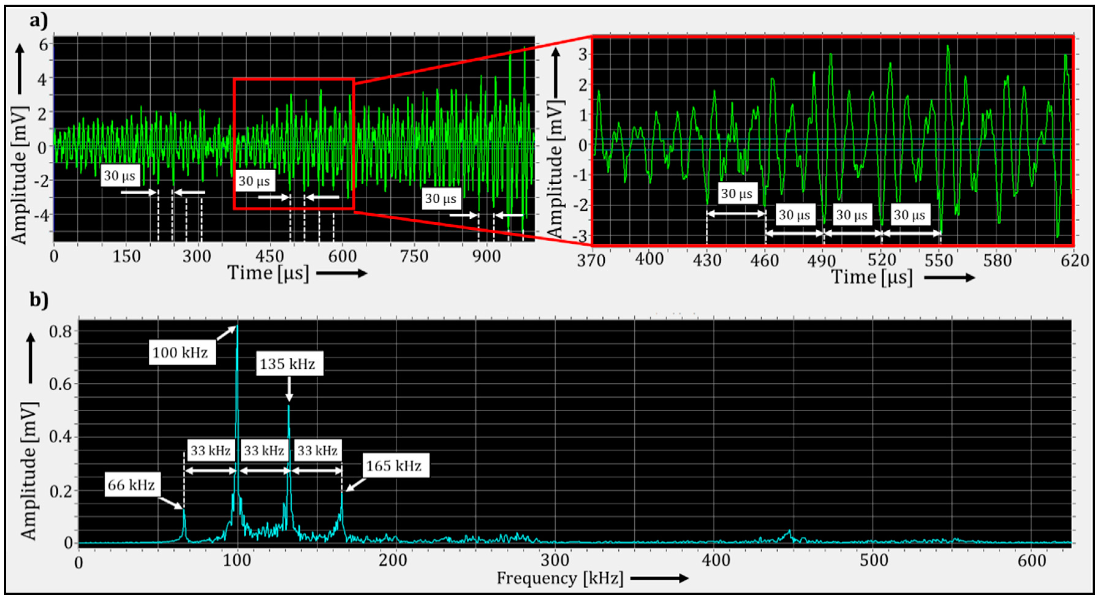
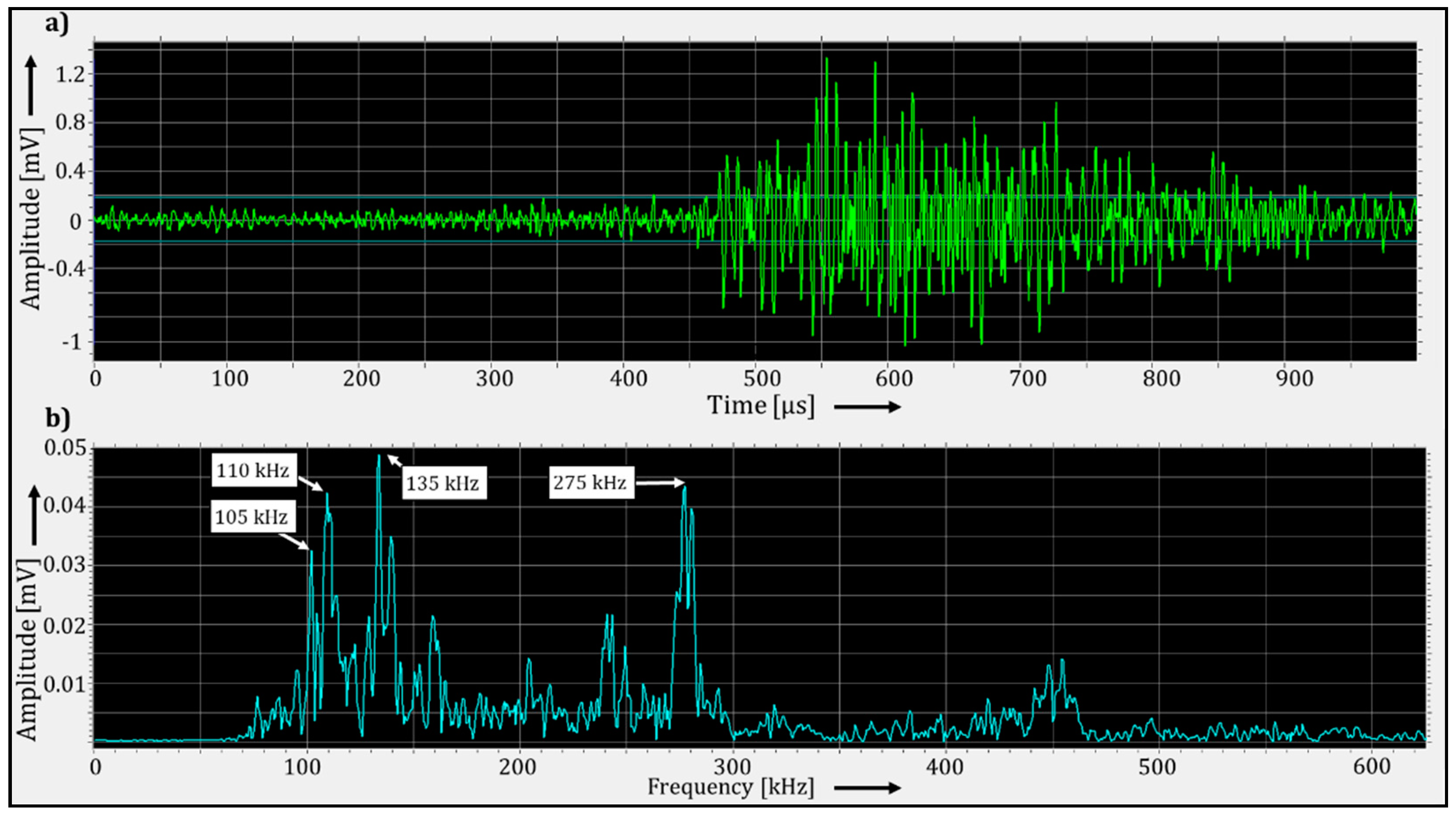
After approximately 2 h of operation without cooling, the time signals and frequency spectra of the hits changed significantly. Before this change was detected, the time signal and the frequency spectra of the hits were similar to the ones obtained during AE measurement under only the presence of abrasive particles. Although the operating frequency range of the employed sensor starts at 125 kHz, the frequency spectra of the newly detected hits show strong peaks around 66, 100, 135 and 165 kHz, which are integer multiples of 33.33 kHz (see
Figure 15). This 33.33 kHz frequency corresponds to a period duration of 30 µs, which can be observed in the time signals of these hits.
Some hits presented such high amplitude values that the measuring system exceeded its measurement range. Although the leakage was only visible one hour after the change in the AE properties was noticed, this change in AE properties could be an indication of damage in the mechanical seal rings.
After detecting the leakage, the barrier supply was restored and the frequencies around 66, 100, 135 and 165 kHz disappeared, as shown in
Figure 16. The signal pattern then reverted to approximately its previous state, as shown in
Figure 12.
6. Discussion
In the previous chapters, the AE signals of a liquid-buffered mechanical seal operated in fault condition modes of the barrier fluid system were presented. A change in the number of detected hits and the amplitudes of the hits between normal operation and the operation mode under fault conditions was considered as an indicator for damage development at an early stage. This is discussed for each fault operation mode in the following.
6.1. Dry-Running Operation
Hits with amplitude values greater than 65 dBAE were often detected during the startup of the agitator vessel system, regardless of whether operation was being carried out with or without the barrier fluid. This is a result of the missing lubrication film inside the sealing gap when the agitator is switched on after standstill. During the startup process, the lubrication film builds up with increasing relative velocity of both seal rings until, depending on the operation conditions, boundary (BL) or mixed lubrication (ML) forms and the initial wear decreases.
As depicted in
Figure 9, operation of the mechanical seal without barrier fluid does not lead to an immediate change in the acoustic behavior, most likely due to the remaining lubricant between the sliding surfaces. This could indicate the presence of BL inside the mechanical seal.
The beginning of dry running was always indicated by a sudden increase in the maximum amplitude of the detected hits, which correlates with the expected drastic change in wear rate during the transition between BL and dry running as described by Hamrock et al. [
6]. In addition, the frequency spectrum of the hits measured during dry-running operation repeatedly showed a characteristic frequency distribution which could clearly be distinguished from AE during operation with barrier fluid. This pattern is characterized by several harmonics of a fundamental frequency of 33 kHz, which could be measured up to the 500 kHz range. The first visible peak in the spectrum was at 66 kHz, despite an operating frequency range of the sensor starting at 125 kHz, most likely due to the high amplitude values of the AE. This pattern could represent the natural frequency of the tribosystem composed by the seal rings and its harmonics.
6.2. Abrasive Particles
The amplitude values of the measured hits that are relevant to an examination of the AE activity were approximately 10 dBAE lower (around 50 dBAE) than the threshold set during the dry running measurement. This is due to the dismantling of the agitator vessel system in order to change the mechanical seal that was damaged during dry-running operation, which affects the attachment between various agitator components and thereby the frequency response between the sensors and the mechanical seals.
The abrupt increases in AE activity shown in
Figure 10 and
Figure 11 could be explained by the presence of a large number of corundum particles that suddenly entered the sealing gap after the pressurized vessel of the barrier fluid system was stirred, which caused a high level of abrasive wear. These peak-like AE activity increases could indicate the transition from normal friction inside the sealing gap to high wear, in this case to high abrasive wear.
As discussed, the different microscopic interaction between the asperities of all the involved surfaces, as well as the microscopic changes due to wear, generate high-frequency signals. Therefore, it is assumed that the excited high-frequency signals could have been stimulated by the abrasive wear between the seal rings and the abrasive particles. The high amplitude values could have resulted from resonances between the excited frequencies and the natural frequency of some of the mechanical seal components.
According to Hase et al. [
10], the AE caused by abrasive wear are characterized by the excitation of a wide frequency range from 250 kHz to 1 MHz with strong peaks at around 250, 450 and 850 kHz. The measured peaks at 275 and 450 kHz are very close to the results of Hase et al. [
10]. The difference between the excited frequencies is probably due to the difference in the materials used and the geometry of the investigated tribosystem. Chung et al. [
17] found a general excitation of frequencies between approximately 100 and 400 kHz with a large peak at 200 kHz for three-body wear. According to Ramadan et al. [
18], the growth and propagation of cracks are characterized by the excitation of a frequency range between 100 and 600 kHz with a large peak at 200 kHz. Since different materials were used in these studies [
17,
18], it can be assumed that three-body wear, as well as the growth and propagation of cracks, was also present during the abrasive lubrication of the mechanical seal used in this work. The overlap of the excited frequency ranges is explained by the fact that the generation of acoustic emission signals during abrasive wear, either between two or three bodies, is related to crack growth and propagation [
10,
17,
18].
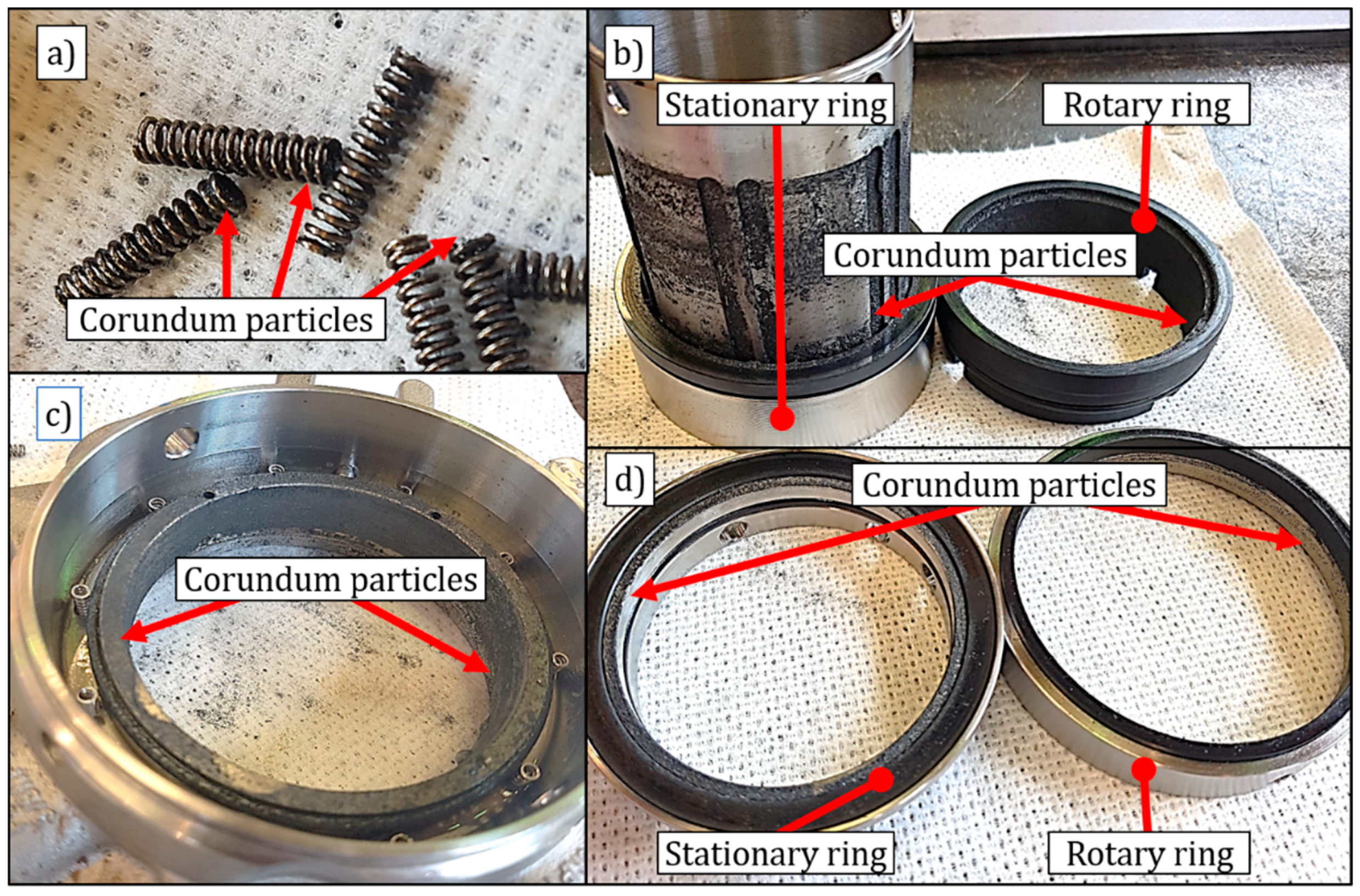
Since the diameter of the corundum particles is in the microscopic range, the particles can settle everywhere in the mechanical seal: in the springs, between the housing and the sliding pair, etc. In
Figure 17, the accumulation of corundum particles throughout the interior of the mechanical seal can be observed. As it is assumed that the measured high frequencies are excited only when the corundum particles generate abrasive wear in the sealing gap, its non-continuous excitation may be due to the fact that the particles experience a centrifugal force when they enter the sealing gap, which directs them to the other parts of the mechanical seal.
6.3. Cooling Failure
At the beginning of the experiment, high amplitude values of the AE were measured. This is an indication of the fatigue suffered by the seal rings due to the continuous abrasive wear induced in the previous experiment. Furthermore, the time signals, as well as the frequency spectra of these AE, showed similar patterns to the ones obtained in the previous experiments with abrasive particles. This acoustic behavior continued during the hole measurement, even after the barrier fluid supply was stopped and restored.
As the barrier fluid supply was interrupted, the heat could not be properly dissipated and the thermosyphon principle was no longer effective. This probably caused the evaporation of part of the remaining barrier fluid inside the sealing gap, which could have caused BL between the seal rings and therefore more frictional heat. This process continued until the barrier fluid supply was restored. The temperature then dropped considerably as seen in
Figure 14. As a drop of lubricant was present on the drain hole of the seal housing (see
Figure 13), it can be assumed that the barrier fluid did not evaporate completely, meaning that lubricant was still present in the mechanical seal and thus prevented dry-running operation. This confirms the presence of BL in the sealing gap.
The damage in the mechanical seal and the time of its onset were determined by a change in the maximum amplitude values of the hits and their respective frequency spectra. As described in the previous chapter, the spectrum of these hits shows a characteristic harmonic pattern with a fundamental frequency of 33 kHz and its harmonics (see
Figure 15). Thanks to the greater amplitude values of these hits, they could be distinguished from those generated due to abrasive wear. This also indicates that the friction mechanism due to prolonged operation under BL conditions caused by the interruption of the barrier fluid supply is the dominant mechanism in this experiment. After the barrier supply was restored, the spectra of the measured hits resembled those measured under the presence of abrasive wear, as illustrated in
Figure 18. The figure shows a comparison between the frequency spectrum depicted in
Figure 12 and the frequency spectrum of a hit measured after the barrier fluid supply was restored.
The frequency pattern depicted in
Figure 15 was very similar to the one observed during the dry running experiments (see
Figure 9), with the exception that in this experiment the frequency spectra only presented harmonics up to 200 kHz. As this frequency pattern disappeared in both experiments after the barrier fluid supply was restored, the presence of a fundamental frequency of about 33 kHz with its respective harmonics could be an indicator for inadequate friction mechanisms inside the sealing gap of a double-acting mechanical seal with a hard/soft seal ring pairing due to deficient lubrication. This could lead to an inadmissible increase in the leakage rate.
Further investigations can be carried out to determine the natural frequencies of the components of a mechanical seal, as well as the natural frequency of the tribosystem. This could provide a better identification of the frequencies excited during operation with fault condition modes. Moreover, the influence of different geometries and material combinations of mechanical seals on the vibrational behavior due to different fault condition modes could be investigated.
Despite increased leakage, the overpressure in the locking system remained constant. The increase of the leakage rate is usually monitored through the overpressure in the barrier fluid system or the liquid level in the pressurized vessel. For this reason, it can be concluded that the measuring systems used in these experiments have detected a defect in the mechanical seal that would not be detected using conventional monitoring methods.
7. Conclusions
This work presents an experimental investigation of typical failure condition modes of a face-end mechanical seal mounted on a test agitator vessel system. The AET was utilized to measure the vibrational response of the friction processes between the seal rings during the fault condition modes, with the aim of detecting the inadequate friction mechanisms that could develop into an inadmissible increase of the leakage rate. The fault condition modes “dry running”, “presence of abrasive particles in the barrier fluid” and “cooling failure in the barrier fluid system” were induced separately and the emitted AE recorded. These fault condition modes represent typical unfavorable conditions for the mechanical seal of an agitator vessel system, which can occur suddenly during normal operation.
It was found that the high-frequency AE analysis is suitable for detecting inadequate friction, as the measuring system was able to detect the induced fault condition modes before leakage was visible at the drain hole.
Dry-running operation and cooling failure caused leaks on the mechanical seal: The former because of the absence of lubrication and the latter due to the insufficient lubrication state (BL), which led in both cases to inadequate friction mechanisms within the sealing gap, causing irreversible damage in the mechanical seal over time, as evidenced by an inadmissible increase in the leakage rate. Although the amplitudes of the measured AE during the onset of the leakage could not be quantified because they exceeded the AMSY-6 measurement range, the significant change in the time signal and frequency spectra indicated the presence of inadequate friction. These signals showed a pattern in the high-frequency range that consisted of the harmonics of a fundamental frequency of about 33 kHz. This pattern is not detectable with the classical vibration diagnostic methods. Additionally, abrasive wear in the sealing gap could be detected independently from the other fault conditions.
8. Outlook
The pressure in the lubrication system remained constant despite the presence of a leakage. Since the mechanical seal is usually monitored through pressure changes in the lubrication system, the leakage would not have been detected by traditional monitoring methods. The basic requirement for a potential broader industrial application is a more economical measuring system compared to the one used in this experiment. It can be assumed that the price of a specialized system for pure industrial use can be significantly lower than the widely applicable system used, with a predominantly scientific field of application.
The amount of data that need to be handled at high sampling frequencies can be greatly reduced by choosing a suitable threshold, since measurements are only taken when the amplitude exceeds this limit. In addition, it is also possible to derive only the AE data from the measured time signals of the hits, but not to store the time signal itself.
The amount of data combined with the characteristics of each detected wear mechanism that can lead to seal failure can be used as a base for future works involving deep learning techniques. The different geometries, material pairings and barriered/buffered fluids or dry gas running mechanical seals will very likely have an influence on the signal characteristics. Therefore, an appropriate machine learning algorithm and its suitable parameters need to be identified and tested. These algorithms generally require sufficient amounts of data, often labeled, whereas algorithms in the “unsupervised learning” category should eliminate that requirement.
Author Contributions
Conceptualization, F.W., M.S., F.S., J.S. and M.M.-A.; methodology, M.M.-A., F.S. and F.W.; validation, M.M.-A., F.S., J.S. and R.K.; formal analysis, M.M.-A., F.W., J.S. and F.S.; investigation, M.M.-A. and F.S.; resources, F.W., M.S., J.S., R.K., F.S.; data curation, M.M.-A. and F.S.; writing—original draft preparation, M.M.-A.; writing—review and editing, M.M.-A., F.S., F.W., J.S. and R.K.; visualization, M.M.-A. and F.S.; supervision, F.W., M.S., R.K. and J.S.; project administration, F.W. and J.S. All authors have read and agreed to the published version of the manuscript.
Funding
This research received no external funding.
Institutional Review Board Statement
Not applicable.
Informed Consent Statement
Not applicable.
Data Availability Statement
The raw data has not been approved by the approval office of BASF SE. The raw data of individual test parts and measurements are available on request from the corresponding author.
Acknowledgments
The authors would like to acknowledge Rui de Oliveira from BASF SE for his great support regarding the applied measurement equipment and for the fruitful discussions. Many thanks go to the entire workshop crew of BASF’s Special Machinery Maintenance department in Ludwigshafen under the leadership of Thorsten Reisser for their technical assistance during the setting up of the agitator vessel test rig and mounting of the mechanical seals.
Conflicts of Interest
The authors declare no conflict of interest.
Abbreviations
The following abbreviations are used in this work:
| AET | Acoustic emission technique |
| AE | Acoustic emissions |
| BL | Boundary lubrication |
| ML | Mixed lubrication |
| HL | Hydrodynamic lubrication |
| dBAE | Decibels of acoustic emissions |
| AMSY-6 | Acoustic Measurement System 6th generation |
| PAC | Physical Acoustics Corporation |
| RMS | Root mean square |
References
- Waidner, P. Gleitringdichtungen. In Handbuch Dichtungspraxis, 4th ed.; Vulkan Verlag: Munich, Germany, 2017. [Google Scholar]
- DIN ISO. Mechanical Vibration—Evaluation of Machine Vibration by Measurements on Non-Rotating Parts; DIN Deutsches Institut für Normierung e.V.: Berlin, Germany, 2018. [Google Scholar]
- Wachsmuth, J. Analyse der Schallemissionssignale aus Ermüdungsrisswachstum und Korrosionsprozesse. Ph.D. Thesis, Technische Universität Berlin, Berlin, Germany, 7 August 2015. [Google Scholar]
- Popov, V. Kontaktmechanik und Reibung; Springer: Berlin, Germany, 2010. [Google Scholar]
- EKATO The Book. Handbuch der Rührtechnik; Ekato Holding GmbH: Freiburg, Germany, 2012. [Google Scholar]
- Hamrock, B.J.; Schmid, S.R.; Jacobson, B.O. Fundamentals of Fluid Film Lubrication; CRC Press: Boca Raton, FL, USA, 2004. [Google Scholar]
- Towsyfyan, H. Investigation of the Nonlinear Tribological Behaviour of Mechanical Seals for Online Condition. Ph.D. Thesis, University of Huddersfield, Huddersfield, UK, 2017. [Google Scholar]
- Ojile, J.O.; Teixeira, J.A.; Carmody, C. Mechanical seal failure analysis. Tribol. Trans. 2010, 53, 630–635. [Google Scholar] [CrossRef]
- Kelemen, S. Potentiale der Schallemissionsanalyse zur Charakterisierung von Trockenlaufenden Friktionssystemen. Ph.D. Thesis, Karlsruher Institut für Technologie, Karlsruhe, Germany, 2012. [Google Scholar]
- Hase, A.; Mishina, H.; Wada, M. Correlation between features of acoustic emission signals and mechanical wear mechanisms. Wear 2012, 292–293, 144–150. [Google Scholar] [CrossRef]
- Zou, M.; Green, I. Real-time condition monitoring of mechanical face seal. Tribol. Ser. 1998, 34, 423–430. [Google Scholar]
- Anderson, W.B.; Jarzynski, J.; Salant, R.F. A condition monitor for liquid lubricated mechanical seals. Tribol. Trans. 2001, 44, 479–483. [Google Scholar] [CrossRef]
- Miettinen, J.; Siekkinen, V. Acoustic emission in monitoring sliding contact behaviour. Wear 1995, 181–183, 897–900. [Google Scholar] [CrossRef]
- Mba, D.; Roberts, T.; Taheri, E.; Roddis, A. Application of acoustic emission technology for detecting the onset and duration of contact in liquid lubricated mechanical seals. Insight Non-Destr. Test. Cond. Monit. 2006, 48, 486–487. [Google Scholar] [CrossRef]
- Almeida, R.S.; Li, Y.; Besser, B.; Xiao, P.; Zhou, W.; Brückner, A.; Langhof, N.; Tushtev, K.; Krenkel, W.; Rezwan, K. Damage analysis of 2.5D C/C-SiC composites subjected to fatigue loadings. J. Eur. Ceram. Soc. 2019, 39, 2244–2250. [Google Scholar] [CrossRef]
- Ferrer, C.; Salas, F.; Pascual, M.; Orozco, J. Discrete acoustic emission waves during stick–slip friction between steel samples. Tribol. Int. 2010, 43, 1–6. [Google Scholar] [CrossRef]
- Chung, K.-H.; Oh, J.-K.; Moon, J.-T.; Kim, D.-E. Particle monitoring method using acoustic emission signal for analysis of slider/disk/particle interaction. Tribol. Int. 2004, 37, 849–857. [Google Scholar] [CrossRef]
- Ramadan, S.; Gaillet, L.; Tessier, C.; Idrissi, H. Detection of stress corrosion cracking of high-strength steel used in prestressed concrete structures by acoustic emission technique. Appl. Surf. Sci. 2008, 254, 2255–2261. [Google Scholar] [CrossRef]
- Scruby, C.; Baldwin, G.; Stacey, K. Characterisation of fatigue crack extension by quantitive acoustic emission. Int. J. Fract. 1985, 28, 201–222. [Google Scholar]
- DGZfP-Fachausschuss. Kompendium Schallemissionsprüfung Acoustic Emission Testing (AT): Grundlagen, Verfahren und praktische Anwendung; Deutsche Gesellschaft für Zerstörungsfreie Prüfung e.V.: Berlin, Germany, 2018. [Google Scholar]
- Vallen Systeme GmbH. AMSY-6 System Description; Vallen Systeme GmbH: Icking, Germany, 2015. [Google Scholar]
- Pascoe, J.; Zarouchas, D.; Alderliesten, R.; Benedictus, R. Using acoustic emission to understand fatigue crack growth within a single load cycle. Eng. Fract. Mech. 2018, 194, 281–300. [Google Scholar] [CrossRef] [Green Version]
Figure 1.
Schematic illustration of the main components of an exemplary mechanical seal. The rotating sealing unit is marked purple and the stationary sealing unit is marked green.
Figure 1.
Schematic illustration of the main components of an exemplary mechanical seal. The rotating sealing unit is marked purple and the stationary sealing unit is marked green.
Figure 2.
Stribeck curve, according to [
6].
Figure 2.
Stribeck curve, according to [
6].
Figure 3.
Principles of AE formation, propagation and detection.
Figure 3.
Principles of AE formation, propagation and detection.
Figure 4.
Schematic representation of the signal processing according to [
20].
Figure 4.
Schematic representation of the signal processing according to [
20].
Figure 5.
Test rig showing the agitator vessel system and the components of the drive unit.
Figure 5.
Test rig showing the agitator vessel system and the components of the drive unit.
Figure 6.
Thermosyphon-type barrier fluid system with pressurized vessel.
Figure 6.
Thermosyphon-type barrier fluid system with pressurized vessel.
Figure 7.
AMSY-6 measuring system setup on the double-acting mechanical seal.
Figure 7.
AMSY-6 measuring system setup on the double-acting mechanical seal.
Figure 8.
Amplitude values of the hits over time during agitator vessel system operation under normal conditions of the barrier fluid system.
Figure 8.
Amplitude values of the hits over time during agitator vessel system operation under normal conditions of the barrier fluid system.
Figure 9.
Amplitude values of the hits over time and the frequency spectrum of a selected hit during dry-running operation of the agitator vessel system.
Figure 9.
Amplitude values of the hits over time and the frequency spectrum of a selected hit during dry-running operation of the agitator vessel system.
Figure 10.
Amplitude values of the hits over time during agitator vessel system operation with abrasive particles in the barrier fluid system.
Figure 10.
Amplitude values of the hits over time during agitator vessel system operation with abrasive particles in the barrier fluid system.
Figure 11.
AE signals with an amplitude value greater than 50 dBAE during agitator vessel system operation with abrasive particles in the barrier fluid system; (a) cumulative number of hits; (b) number of hits that occurred over the course of the previous 30 s.
Figure 11.
AE signals with an amplitude value greater than 50 dBAE during agitator vessel system operation with abrasive particles in the barrier fluid system; (a) cumulative number of hits; (b) number of hits that occurred over the course of the previous 30 s.
Figure 12.
AE properties of a hit during the abrupt increases of AE activity; (a) time signal; (b) frequency spectrum.
Figure 12.
AE properties of a hit during the abrupt increases of AE activity; (a) time signal; (b) frequency spectrum.
Figure 13.
Close-up of the mechanical seal with leakage in the drain hole of the seal housing; (a) during the induced cooling failure; (b) after the reestablishment of the barrier fluid supply.
Figure 13.
Close-up of the mechanical seal with leakage in the drain hole of the seal housing; (a) during the induced cooling failure; (b) after the reestablishment of the barrier fluid supply.
Figure 14.
Amplitude values of the hits over time during agitator vessel system operation with two failures in the barrier fluid system: presence of abrasive particles and cooling failure through the interruption of the barrier fluid supply.
Figure 14.
Amplitude values of the hits over time during agitator vessel system operation with two failures in the barrier fluid system: presence of abrasive particles and cooling failure through the interruption of the barrier fluid supply.
Figure 15.
AE properties of a hit during agitator vessel system operation with an induced failure in the barrier fluid system; (a) time signal; (b) frequency spectrum.
Figure 15.
AE properties of a hit during agitator vessel system operation with an induced failure in the barrier fluid system; (a) time signal; (b) frequency spectrum.
Figure 16.
AE properties of a hit after the barrier fluid supply was restored; (a) time signal; (b) frequency spectrum.
Figure 16.
AE properties of a hit after the barrier fluid supply was restored; (a) time signal; (b) frequency spectrum.
Figure 17.
Accumulation of corundum particles inside the mechanical seal; (a) springs; (b) product side seal ring pair; (c) seal housing; (d) atmospheric side seal ring pair.
Figure 17.
Accumulation of corundum particles inside the mechanical seal; (a) springs; (b) product side seal ring pair; (c) seal housing; (d) atmospheric side seal ring pair.
Figure 18.
Comparison between two frequency spectra of different measurements; (
a) frequency spectrum of the hit depicted in
Figure 12; (
b) frequency spectrum of a detected hit after the barrier fluid supply was restored when simulating a cooling failure.
Figure 18.
Comparison between two frequency spectra of different measurements; (
a) frequency spectrum of the hit depicted in
Figure 12; (
b) frequency spectrum of a detected hit after the barrier fluid supply was restored when simulating a cooling failure.
Table 1.
Components of the agitator vessel system and their attributes.
Table 1.
Components of the agitator vessel system and their attributes.
| Feature | Description |
|---|
| Vessel storage capacity | 500 L |
| Vessel height | 1450 mm |
| Vessel inner diameter | 786 mm |
| Shaft diameter | 50 mm |
| Agitator bearings | 2× SKF 6309-2Z |
| Agitator type | 3-blade propeller |
| Gear manufacturer | Lenze (Hameln, Germany), type 12.410.10.1.0 |
| Gear ratio | 3.15 |
| Motor manufacturer | ATB (Nordenham, Germany), type: CD112M-4 Y2 |
| Motor output power | 4 kW |
| Motor nominal speed | 1460 rpm |
| Belt drive pulley ratio | 0.76 |
| Publisher’s Note: MDPI stays neutral with regard to jurisdictional claims in published maps and institutional affiliations. |
© 2021 by the authors. Licensee MDPI, Basel, Switzerland. This article is an open access article distributed under the terms and conditions of the Creative Commons Attribution (CC BY) license (http://creativecommons.org/licenses/by/4.0/).


 ,
, 


