Article

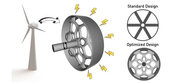
Reducing the Structural Mass of Large Direct Drive Wind Turbine Generators through Triply Periodic Minimal Surfaces Enabled by Hybrid Additive Manufacturing

by
Austin C. Hayes
and
Gregory L. Whiting
*,†
Paul M. Rady Department of Mechanical Engineering, University of Colorado Boulder, Boulder, CO 80303, USA
*
Author to whom correspondence should be addressed.
Current address: 1111 Engineering Drive Engineering Mechanical Wing, Boulder, CO 80309, USA.
Submission received: 19 January 2021 / Revised: 11 February 2021 / Accepted: 18 February 2021 / Published: 1 March 2021
(This article belongs to the Special Issue Recent Advances in Wind Energy)

Abstract

:
As the power output of direct drive generators increases, they become prohibitively large with much of this material structural support. In this work, implicit modeling was coupled to finite element analysis through a genetic algorithm variant to automate lattice optimization for the rotor of a 5 MW permanent magnet direct drive generator for mass reduction. Three triply periodic minimal surfaces (TPMS) were chosen: Diamond, Schwartz Primitive, and Gyroid. Parameter and functionally graded lattice optimization were employed to reduce mass within deflection criteria. Inactive mass for the 5 MW Diamond, Schwartz Primitive, and Gyroid optimized designs was 10,043, 10,858, and 10,990 kg, respectively. The Schwartz Primitive rotor resulted in a 34% reduction in inactive mass compared to a 5 MW baseline design. Radial and axial deflections were below the critical limit of 0.65 and 32.17 mm, respectively. The lowest torsional deflection was seen in the Schwartz Primitive TPMS lattice at 3.89 mm. Based on these designs, hybrid additive manufacturing with investment casting was used to validate manufacturability in metal. A fused deposition modeling (FDM) TPMS topology was printed for validation of the FEA results. Comparison between digital image correlation of the FDM printed design and FEA design resulted in a 6.7% deformation difference for equivalent loading conditions.

Graphical Abstract

1. Introduction

As of 2019, wind energy provided 7.2% of the US electricity supply and is projected to grow to 12.5% by 2050 [1]. Further research into wind turbine generator design will enable higher powered machines with cost savings to drive down the levelized cost of electricity and further increase wind penetration into the electricity grid.
In a direct drive generator, the gearbox is removed with direct coupling of the blade shaft to the generator. This is of particular interest as it can lead to improved reliability and lower levelized cost of energy by removing expensive gearbox replacements and transmission losses [2]. However, high torque is needed in order to maintain high power output at lower rotational speeds (8–15 rpm). With fixed current density, this requires a large outer diameter [3]. For a 5 MW direct drive generator, the structural mass can be up to 80% of its entire weight [4]. This large mass poses a particular concern for offshore installation where direct drive generators hold potential for greater reliability. As a result, much research has focused on reducing structural material mass. Zavvos et al. used commercial shape optimization (ANSYS) resulting in 20% mass reduction of a 5 MW permanent magnet direct drive (PMDD) generator [5]. Research into reducing structural mass through shape optimization has lacked a link to manufacturing these large complex designs on a large scale. Mueller et al. [6] developed a C-core electromagnetic topology with both longitudinal and transverse flux paths whose placement negates magnetic loading leading to 55% lower mass for a prototype 100 kW machine.
Lattice structures have garnered attention due to their ability to produce high strength to weight ratios. Nature holds many examples of lattices. Metals exhibit crystal structures including body centered cubic and face centered cubic lattices [7]. Bees create a honeycomb lattice in order to maximize packing ratio with minimal material [8]. Endoplasmic Reticulum and mitochondrial membranes depict gyroid and diamond lattice structures during cellular stress, though biological significance of this behavior is unknown [9]. Triply periodic minimal surfaces (TPMS) such as a Gyroid, Diamond, and Schwartz Primitive are mathematical surfaces which are invariant under a rank three lattice of translation. In simpler terms, they contain three axis of symmetry, locally minimize their surface area, and are an area of study for structural lightweighting. TPMS lattice functions of arbitrary cells and volume fractions are obtained by finding the isosurfaces of the TPMS equations [10,11]:
U G y r o i d = c o s ( k x x ) s i n ( k y y ) + c o s ( k y y ) s i n ( k z z ) + c o s ( k z z ) s i n ( k x x ) t
U D i a m o n d = s i n ( k x x ) s i n ( k y y ) s i n ( k z z ) + s i n ( k x x ) c o s ( k y y ) c o s ( k z z ) + c o s ( k x x ) s i n ( k y y ) c o s ( k z z ) + c o s ( k x x ) c o s ( k y y ) s i n ( k z z ) t
U S c h w a r t z P = c o s ( k x x ) + c o s ( k y y ) + c o s ( k z z ) t
The isosurface becomes the boundary between solid and void regions and k i determines the periodicity given by Equation (4). The value of k i determines the periodicity and is broken down into n i , the number of cell repetitions in each direction, and L i , the absolute size of the structure in each direction.
k i = 2 π n i L i ( w h e r e i = x , y , z )
With advances in additive manufacturing, TPMS structures are able to be manufactured leading to increased research on their potential engineering utility. These structures are challenging to manufacture through conventional means due to internal cavities and overlapping features. However, TPMS structures have high specific strength and energy absorption making them advantageous for structural support [12]. They are easily fabricated using additive techniques such as fused deposition modeling, polyjet material deposition, or selective laser sintering. Maconachie et al. [12] utilized fused deposition modeling with Gyroid TPMS structures in order to develop design rules governing its structural properties. Vanez et al. [13] used electron beam melting of Ti-6Al-4V for human cancellous bone implants finding greatest strength to weight ratios for strut angles under 35 ° . Maskery et al. [10] found that the Schwartz Primitive TPMS had an elastic modulus 2.06 times that of the Gyroid TPMS. This is supported by previous work by Afshar et al. who found the ratio to be 1.94 [14]. Furthermore, it was seen that the Schwartz Primitive structures depict stretching dominated deformation while the Gyroid and Diamond structures showed bending dominated deformation. Despite a higher elastic modulus, the Schwartz Primitive TPMS had highly localized plastic deformation, structural buckling, and low failure strain. This suggests the Schwartz Primitive may perform best in high strength applications where one loading direction dominates. These studies indicate an optimal TPMS support structure strongly depends on multiple parameters including periodicity, strut angle, strut thickness, and cell size.
Additive manufacturing (AM) has enabled the design of extremely complex geometries with fewer design rules [15,16]. Internal structures [17], increased surface area [18], conformal cooling passages [19], and lattice structures [20,21,22,23,24,25] can be manufactured just as easily as simple, planar parts. Now, optimization methods and structural analysis can be coupled to create designs catered for functionality. For example, Haertel et al. [26] used topology optimization to create an air cooled heat exchanger that had a 71% greater conductance per unit volume. These designs had tendril-like structures impossible to manufacture without additive manufacturing. However, additive manufacturing of extremely large structures is limited due to machine size. This is especially true for metal additive manufacturing techniques such as laser metal deposition (LMD) [27], direct metal laser sintering (DMLS) [28], and electron beam melting (EBM) [28].
To fully take advantage of additive manufacturing, components must be optimized for functionality. Two main optimization approaches are parameter optimization and topology optimization. The first [29,30], takes a given number of inputs and uses any deterministic or stochastic optimization scheme in order to iterate parameters towards an optimal solution. This includes genetic algorithms, particle swarm approaches, and Monte-Carlo analysis. The former [31,32,33,34], uses a numerical process to add or remove material penalizing for discontinuous or disadvantageous structures while simultaneously calculating the strain field in order to minimize or maximize an objective function. The typical structural compliance problem has two conflicting conditions, for example, maximizing stiffness while minimizing mass where an optimal condition exists with the maximum stiffness at minimum mass. Theoretically, a topology optimized approach should achieve a global minima or maxima; however, many times, convergence leads to local minima. In this case, a different approach is needed. Daynes et al. [35] combined both methods by using topology optimization to remove unnecessary material and then applied a strain optimized lattice structure from finite element analysis (FEA) results to reduce compliance of a bracket by 13% and improve manufacturability. This study employs a genetic algorithm variant for parameter optimization coupled with implicit modeling to control the topology of complex lattice structures for PMDD generator inactive mass.
Large electric machines are a good application space of structural optimization using minimal surfaces due to their large size and reliance on structural support for functionality (such as maintaining a 5 mm air gap radius on a 5 m machine). Specifically, we look to the rotor of wind turbine direct generators for mass reduction using implicit structural optimization. Advances in lightweighting and modeling complex lattices holds promise for further mass reduction of these generators.
Past structural mass reduction attempts have focused on electromagnetic topology design changes [6], optimization with 1D models [4,36] or low resolution topology optimization [5]. This study attempts to further reduce structural mass of PMDD generators by improving rotor design through evolutionary structural optimization with implicitly generated triply periodic minimal surfaces. We combine advances in implicit modeling and understanding of triply periodic minimal surfaces with finite element analysis using a closed loop evolutionary algorithm in order to create a tool for lightweighting PMDD rotors with TPMS structures. To the authors’ knowledge, this research is the first implementation of optimizing TPMS structures for large electric machine design.
This research will explain implicit modeling as used for PMDD generators as well as the loading condition methods and lattice optimization and simulation techniques. Experimental validation with digital image correlation on a scaled part will be explained. Results and discussion of the genetic algorithm lattice simulation and functional grading are then depicted showcasing the mass savings associated with TPMS lattices for wind turbine generators.

2. Materials and Methods

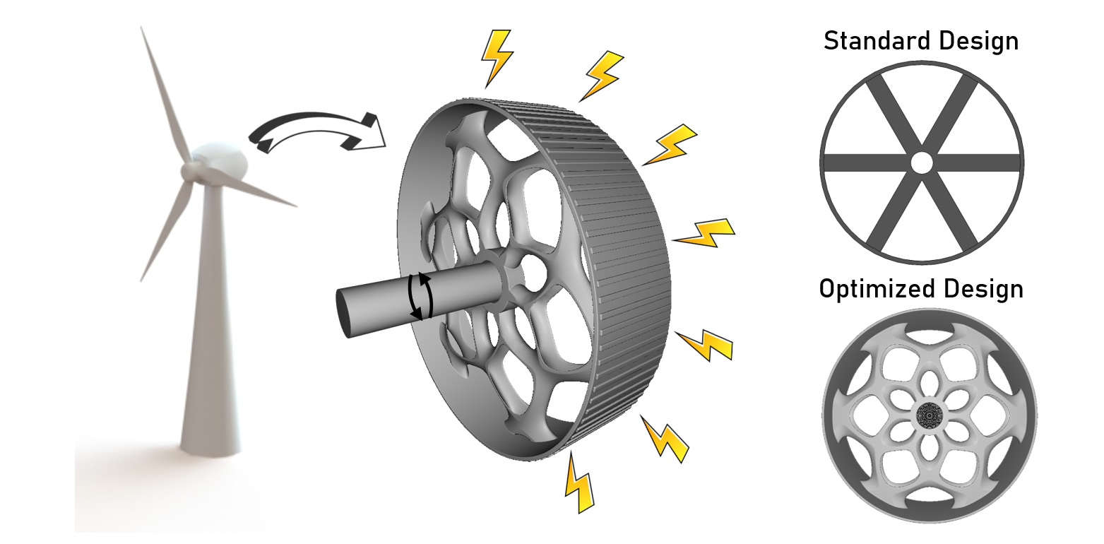
2.1. Implicit Modeling

Implicit modeling eliminates the need for faces, vertices, and edges by representing the boundary between solid and void regions through a signed distance function. It is orders of magnitude faster than traditional CAD methods as operations are performed on the function representation and then sampled at varying resolutions for visualization. Consider the implicit equation of a torus in Equation (5).
( x 2 + y 2 R ) 2 + z 2 = r 2
where x, y, z, are Cartesian coordinates, R is the major radius, and r is the minor radius. In order to transform this equation into an boundary defined implicit representation of a torus, we normalize by the minor radius and evaluate to zero (Equation (6)).
F ( x , y , z ) = ( x 2 + y 2 R ) 2 + z 2 r 2 1
In this form, evaluation of the implicit function for x, y, z resulting in values greater than zero define void regions, less than zero indicate regions inside the part, and equals zero indicates the boundary between part and void (Figure 1). Software package Ntopology Element [37] was used for lattice implicit modeling of all lattices. Three minimal surfaces were explored in this study: Gyroid, Schwartz Primitive, and Diamond.

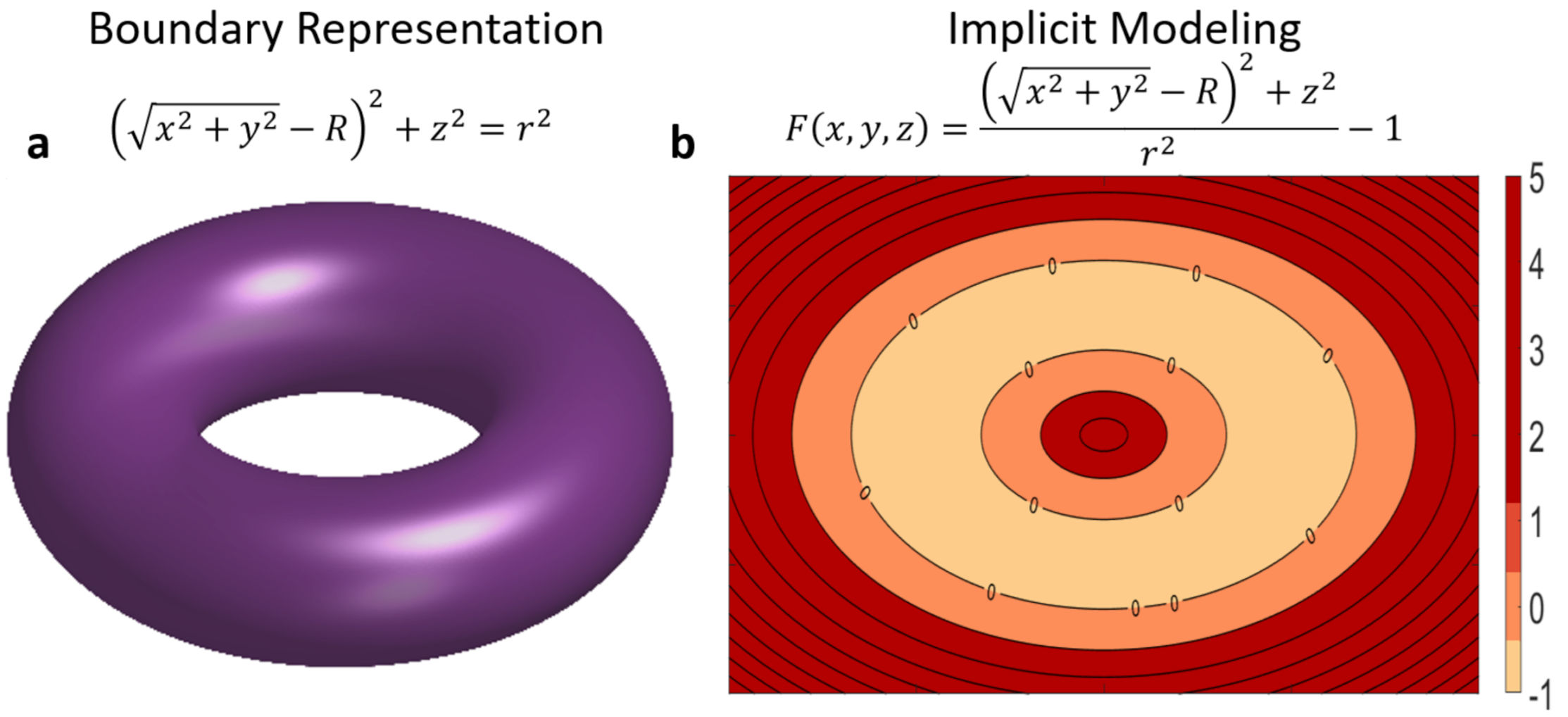
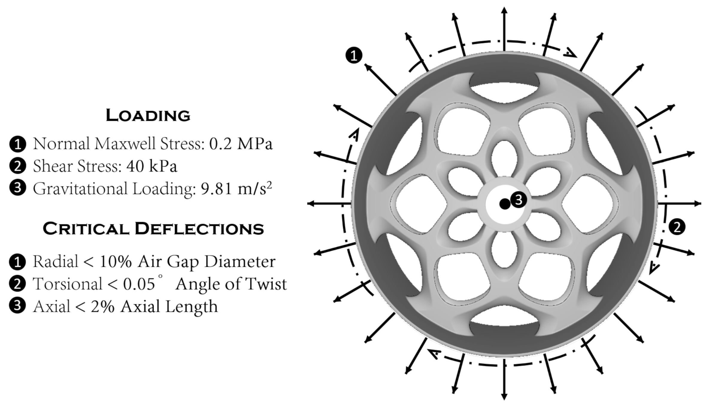
2.2. Rotor Loading Criteria

Three main forces act on the rotor during operation seen in Figure 2. Due to its low speed (8–15 rpm), a high torque exists which is the useful work to produce electricity. Due to electromagnetic interactions, a normal component of the Maxwell stress acts radially outward. Finally, gravity acts on the entire structural and cannot be neglected due to the large mass of a PMDD generator. Load values used in this study agree with those used in the literature for a 5MW radial flux (RF) PMDD machine [4,36]. The normal component of the Maxwell stress was assumed to be 0.2 MPa, the shear stress arising from the torque 40 kPa, and a gravitational acceleration of 9.81 m/s2. The 5 MW deflection criteria were determined such that the radial deflection was less than 10% of the air gap diameter (to avoid closing the airgap), the torsional deflection less than 0.05 ° angle of twist (to prevent shear failure), and the axial deflection less than 2% the axial length (to prevent transportation damage). For our 5 MW machine this results in a maximum radial, torsional, and axial deformations of 0.65, 2.84, and 32.17 mm, respectively. For FEA analysis, the rotor was assumed to be homogeneous and isotropic and made out of structural steel with an elastic modulus of 200 GPa, Poisson ratio of 0.28, and density of 7850 kg m−3. The rotor was assumed to be well cooled and thermal effects assumed to be mitigated.

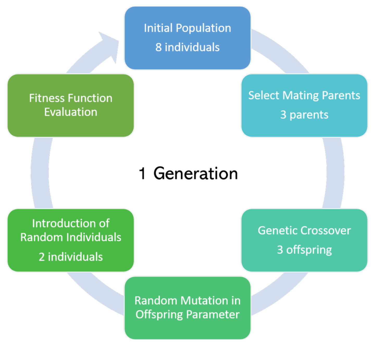
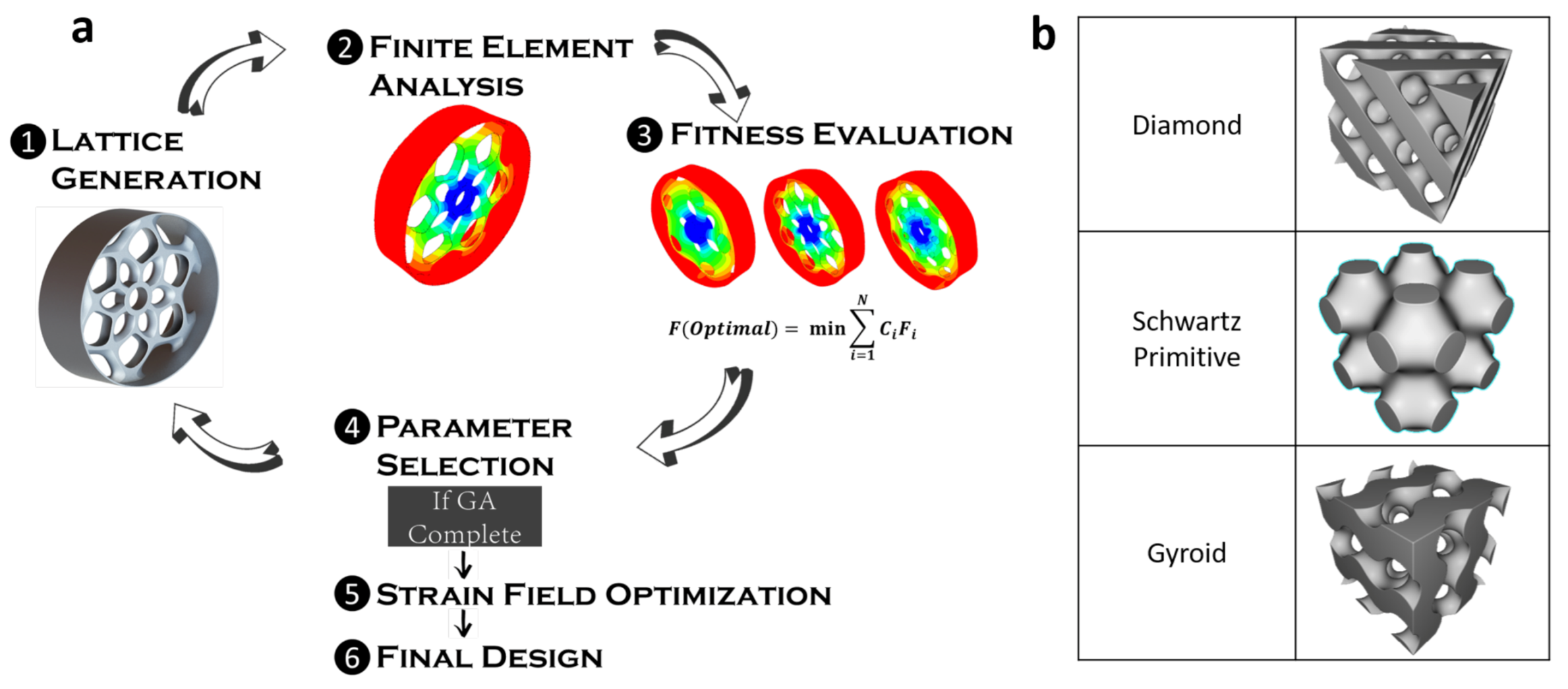
2.3. Lattice Optimization and Simulation

Implicit lattice creation and functionally graded lattices were performed using the software package nTopology Element [37]. This was selected due to its ability to quickly create large lattice structures, high parametrization of the lattice for complete control, ability to input custom lattices, and API interface with python. A cylindrical TPMS lattice was used. Shear loads, large problems, precise material control, and nonlinearity are a challenge within nTopology. Therefore, once the lattice was generated, it was exported to Abaqus [38] for structural analysis. TPMS optimization is challenging due to high computational costs for large structures spanning multiple length scales. In this case, to capture the lattice structures, length scales of three orders of magnitude were needed (≈ 10 2 to 10 1 m). A genetic algorithm (GA) variant and custom linkage was employed in python to connect nTopology and Abaqus in order to conduct parameter optimization to adjust the lattice parameters towards a more optimal solution (Figure S2). A GA was used due to the large sample space and expectation of many local minima as mass is minimized while stiffness maximized. A genetic algorithm generates individuals in a population with genes representative of parameters. Variability is introduced through parameter crossover in mating individuals and through random mutation. The GA variant used is shown in Figure 3. In this case, variability was increased to reduce the likelihood of local minima by introducing new random individuals in each generation. The presence of many local minima would hinder traditional gradient based approaches. The GA approach was compared to random sampling and found to converge faster and with an overall lower fitness score (Figure S3). The optimization scheme is shown in Figure 4. A mesh analysis was performed and a 35 mm mesh element size selected for maximum feature resolution at lowest computational resource usage (Figure S1). An additional mesh analysis was performed at the conclusion of each optimization step with results indicating less than 5% change in deflection with increasing mesh size past 35 mm. The GA is performed for three minimal surfaces: Gyroid, Schwartz Primitive, and Diamond. After parameter optimization, the strain field in the weakest direction (torsional for this study) was used as an input field to selectively thicken or thin the lattice structure. This functionally graded lattice was used to further optimize the TPMS structure. Functionally graded lattice optimization was performed for each minimal surface to determine the final designs.

2.4. Hybrid Additive Manufacturing

Many minimal surface geometries are impossible to manufacture through conventional approaches (CNC, Lathe, Mill) due to internal curvature and cavities. Metal additive manufacturing enables these complex surfaces but is limited in size. GE’s Spectra L, the largest electron beam melting machine, maintains a diameter of 350 mm and height of 430 mm [39]. GE’s X Line 2000R is similarly the largest direct metal laser sintering (DMLS) machine with a build chamber of 800 × 400 × 500 mm [40]. Both fall short for manufacturing large PMDD generators as found in commercial wind turbines which can have diameters of 6 m for a 5 MW machine. This study explores manufacturing methods combining additive technologies with traditional techniques such as casting, a process known as hybrid additive manufacturing. Hybrid additive manufacturing can be used to economically manufacture these large complex lattices. For proof of concept, investment casting of a wax-impregnated fused-deposition modeling part was carried out by the Art Castings of Colorado [41]. Successful investment casting of the complex minimal surface geometries suggests extension to other hybrid additive manufacturing technologies such as powder-binder jetting for large scale sand casting. Typically, the rotor is made of structural steel. Due to material availability, proof of concept hybrid AM-casting was done with bronze.

2.5. Experimental Validation

In order to validate the FEA model, digital image correlation (DIC) was used for a prototype part fabricated with an FDM printer (Raise 3D, Irvine, CA) with PLA. PLA was chosen for ease of manufacturing. Small deformations result in a linear elastic behavior. This suggests that only material properties and shape will influence deformation results under a given loading scenario. For this reason, the PLA printed model simply loaded with a torque arm was used to validate simulation accuracy. A simulation matching the FDM printed loading scenario was ran on a scaled (200 mm diameter) optimized Schwartz Primitive design with PLA material properties. These results were validated with DIC of the same printed PLA model. A torsion arm and shaft were printed concurrently to allow loading and support of the part. The final printed part can be seen in Figure S6. A Canon Rebel 12.2 MP camera with a resolution of 83 μ m per pixel was used with open source software DICe [42]. A speckle pattern was applied with white and black spray paint. A known mass was loaded on the torsion arm and full field 2D strain data captured through DIC. PLA material properties for the specific filament were validated through tensile testing of the exact prototype part printing conditions as seen in Figure S4 and shown to agree with manufacturer data.

3. Results and Discussion

3.1. Simulation

A structural optimization tool using parameter optimization with an evolutionary algorithm was developed for wind turbine PMDD generator rotor optimization. First, parameter optimization with the GA resulted in proper lattice parameters subject to fitness criteria. Next, these optimized lattices were further optimized by selective thickening or thinning of the lattice thickness according to the strain field. At the end of each minimal surface and GA run, a mesh study was ran on the final design to determine convergence as the simulations were originally ran with a courser mesh to reduce computational load (Figure S1). Compared to random sampling, the GA reached a more optimal solution with a significantly lower fitness score with fewer generations (Figure S3).

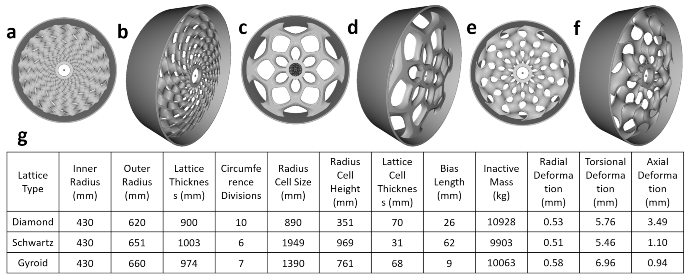
3.1.1. GA Optimized Minimal Surfaces

For each minimal surface, seven different parameters were varied shown in Figure 5. The outer ring radius (the amount of radial material around the shaft), the lattice depth (how much of the space in the thickness of the rotor the lattice was allowed to fill), the number of circumference repetitions (the periodicity of the lattice), the radius cell size (the radius of a unit cell in cylindrical coordinates), the radius cell height (the height of the unit cell in cylindrical coordinates), the lattice cell thickness (the thickness of the lattice support material), and the bias length (the radial offset of the unit cell). The rotor ring outer radius and thickness of the rotor back iron was fixed for a 5 MW machine at 3254 and 66 mm, respectively and the axial length 1609 mm allowing comparison with past literature [36].
For the GA, first, a random population with seven chromosomes representing the seven parameters was initialized. Next, a given number of individuals were selected to mate with a central chromosome crossover point. Mutations were introduced in these offspring randomly impacting one parameter. To increase randomness, two randomly generated individuals were added to the population pool. Finite element analysis was used to calculate deflections and mass in order to determine each individual’s fitness score (Equation (7)). A given number of individuals with the lowest fitness score were then selected as parents to begin the process again and the cycle repeated 200 generations to ensure convergence.
F ( O p t i m a l ) = m i n ( C 1 F R a d i a l + C 2 F T o r s i o n a l + C 3 F L a t t i c e + C 4 F I n n e r r i n g )
F R a d i a l = δ r a d i a l δ r a d i a l c r i t δ r a d i a l c r i t
F T o r s i o n a l = δ t o r s i o n a l δ t o r s i o n a l c r i t δ t o r s i o n a l c r i t
F L a t t i c e = M l a t t i c e M o u t e r r i n g
F I n n e r r i n g = M i n n e r r i n g M o u t e r r i n g
The individual deflection fitness functions (Equation (8)–(11)) were normalized to their critical limits and the lattice and inner ring mass fitness functions relative to the constant outer ring mass. δ r a d i a l represented the radial deformation of the TPMS new design with δ r a d i a l c r i t representing the critical radial limit seen in Figure 2. The same nomenclature was used for the torsional deflection. M l a t t i c e represents the lattice mass with the lattice mass fitness score subset found by normalizing the lattice mass to the rotor active mass (outer ring mass). The inner ring fitness score subset was found by dividing the mass of the inner ring ( M i n n e r r i n g ) by the mass of the rotor outer ring ( M o u t e r r i n g ). The constants were used as weighting parameters to assign relative importance of each fitness criteria. For TPMS parameter optimization, mass was selected as the highest fitness score contributor by selecting radial and torsional weighting constants as 1, the lattice mass weighting factor as 10, and the inner ring weighting factor as 20 ( C 1 = 1 , C 2 = 1 , C 3 = 10 , C 4 = 20 ). These factors ensured a unit change in mass reflected a stronger fitness score variation preventing an optimal solution by simply minimizing deflection with high mass. These constants were chosen experimentally.
Results of the parameter optimization for each minimal surface as well as the corresponding design is given in Figure 6. The Diamond, Schwartz Primitive, and Gyroid TPMS lattices had a total inactive mass (mass only for structural support—the inner ring and lattice) of 10,928, 9903, and 10,063 kg, respectively. The reference mass of the 5 MW spoked arm rotor was 16450 kg with a radial, torsional, and axial deflection of 0.56, 2.36, and 0.20 mm, respectively [36]. Radial deflections were 0.53 mm for the Diamond TPMS, 0.51 mm for the Schwartz Primitive TPMS, and 0.58 mm for the Gyroid TPMS. Torsional deflections for Diamond, Schwartz Primitive, and Gyroid TPMS lattices were 5.76, 5.46 mm, and 6.96 mm, respectively. Axial deflections were well below the critical limit of 32.17 mm and were 3.49 mm for Diamond, 1.10 mm for Schwartz Primitive, and 0.94 mm for Gyroid TPMS lattices. The parameter optimization of all three minimal surfaces resulted in up to 40% inactive mass savings from the spoked arm design; however, the torsional deflection for all three was above the deflection criteria of less than 0.05 ° angle of twist (2.84 mm).

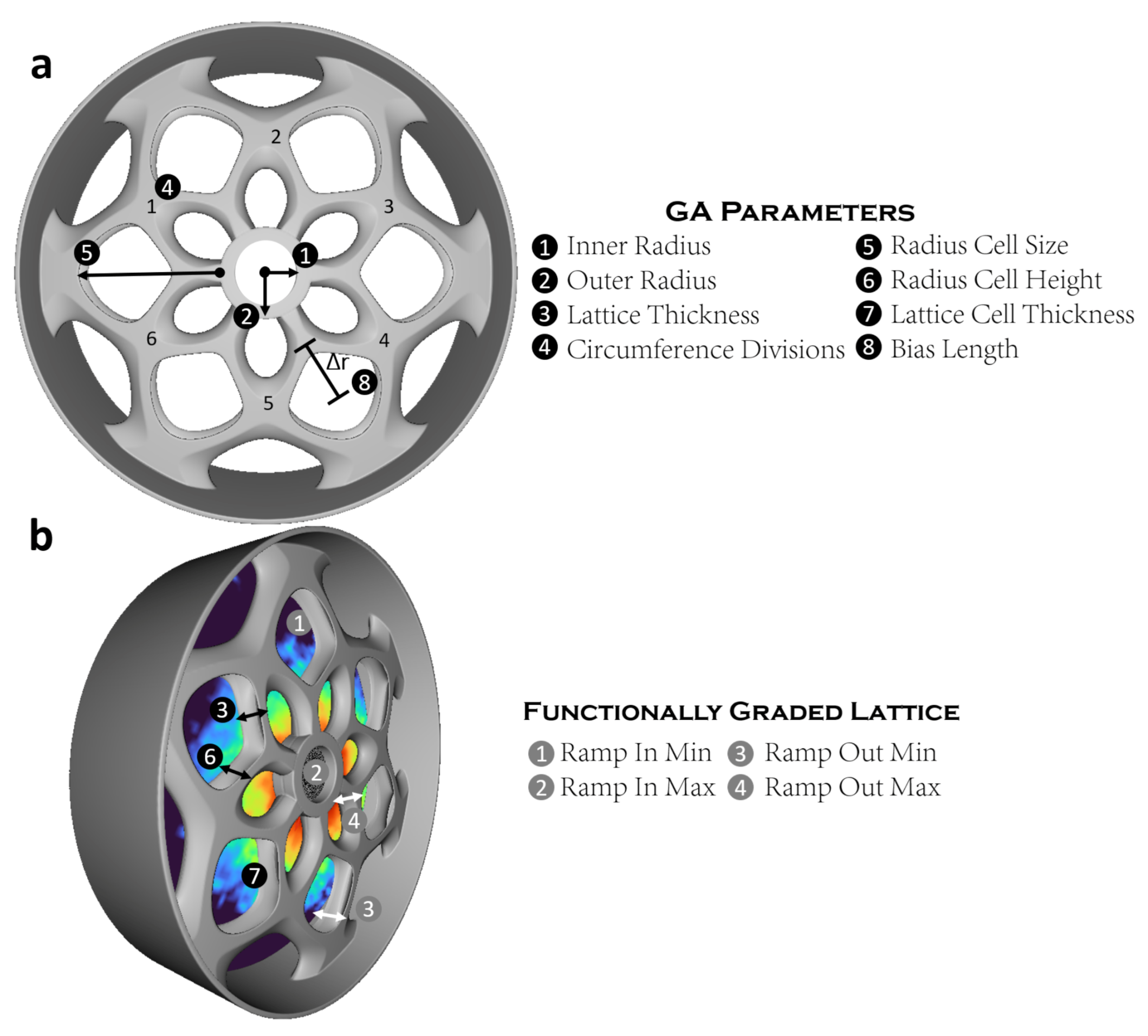
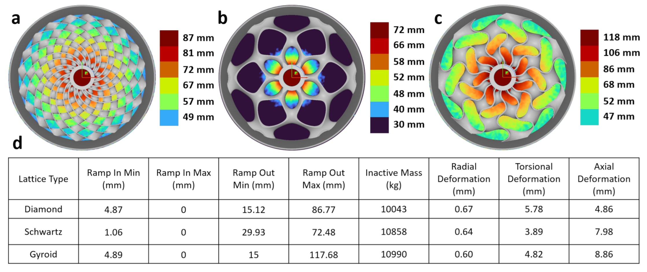
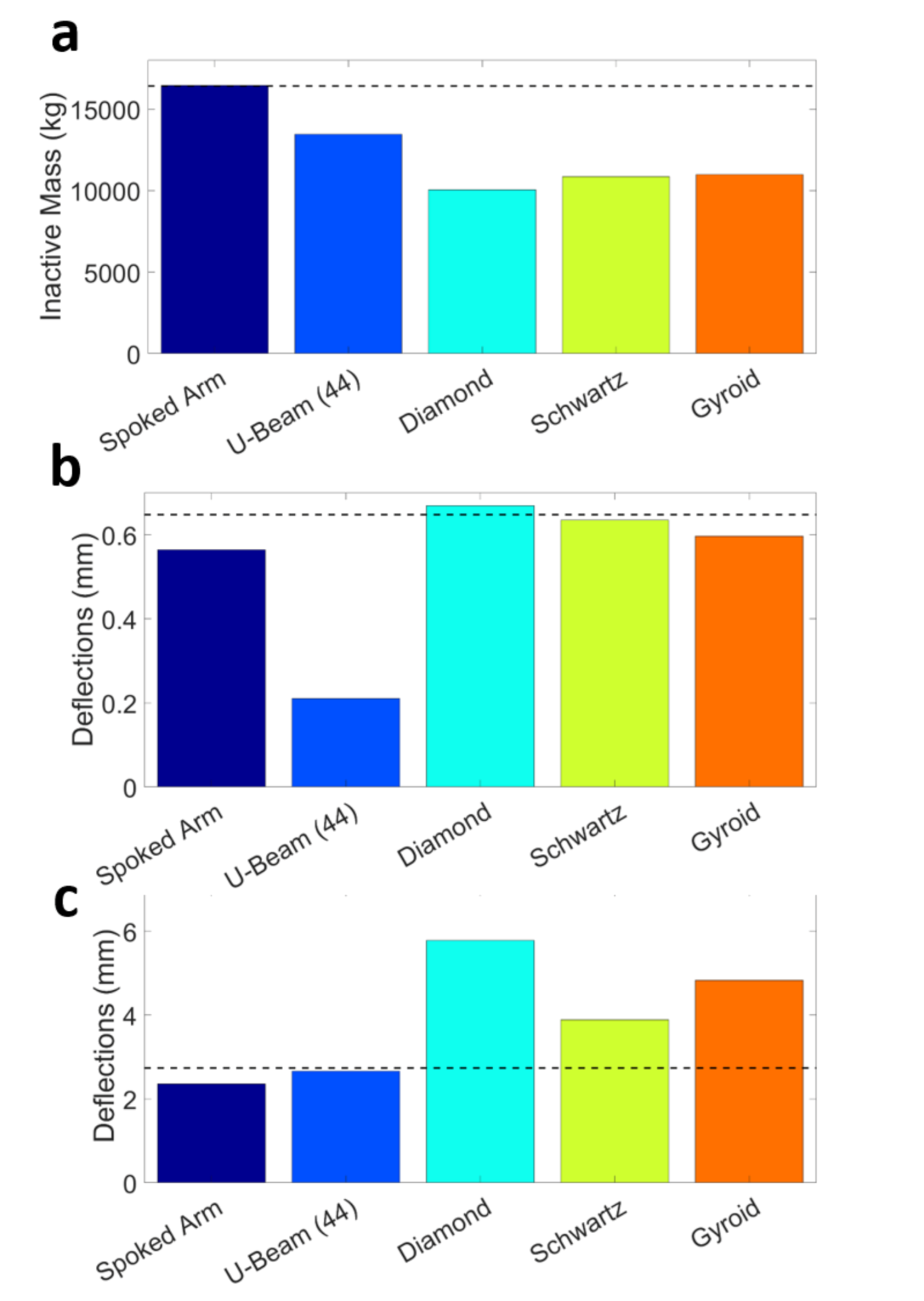
3.1.2. Functionally Graded Lattice Optimization

In order to reduce the torsional deflection without sacrificing mass savings, functionally graded lattice optimization was performed on the best previous parameter optimized design. Note that it was necessary to run this secondary analysis as a separate optimization cycle and not concurrent with the first in order to first obtain design specific nodal strain profiles and create functionally graded lattices. Nodal strain data were extracted from finite element results and the torsional strain isolated and converted to millimeters of deflection. Next, the nodal torsional strain data were converted to a torsional strain field. The torsional strain field was then used to selectively thicken or thin the lattice at all nodal points. By using the torsional strain field, optimization of the field ramp values caters specifically to minimizing torsional deflection while maintaining mass savings. Optimization was performed using the same GA discussed previously. The best lattice parameters for each TPMS were fixed and only the ramp in minimum (FEA torsional deflection to begin field ramp), ramp in maximum (FEA torsional deflection to end field ramp), ramp out minimum (minimum lattice cell thickness to begin ramp), and ramp out maximum (maximum lattice cell thickness to end ramp) were optimized (Figure 5). As an example, a ramp in minimum, ramp in maximum, ramp out minimum, and ramp out maximum values of 1.06, 0.00, 29.93, and 72.48 mm, respectively for the Schwartz Primitive TPMS indicates the lattice cell thickness will vary at radii with FEA torsional deflections between 0 and 1.06 mm with decreasing lattice thickness radially outward from 72.48 mm to 29.93 mm. This means in order to minimize torsional deflection, the thickest portion of the lattice is near the center and then gradually thins with increasing radius to a minimum value.
After functionally graded lattice optimization, radial deformations for the Diamond, Schwartz Primitive, and Gyroid TPMS lattices were 0.67, 0.64 and 0.60 mm, respectively. Torsional deformations were 5.78, 3.89, and 4.82 mm, respectively. Axial deformations were 4.86, 7.98, and 8.86 mm, respectively. Inactive mass was 10,043 kg for the Diamond lattice, 10,858 kg for the Schwartz Primitive lattice, and 10,990 kg for the Gyroid lattice. Tabulated results with each TPMS strain field ramp parameters and the corresponding optimized lattice with lattice thickness overlaid can be found in Figure 7.
The Schwartz lattice depicted lowest torsional deflection out of the three TPMS lattices. This agrees with literature finding the Schwartz Primitive TPMS had an elastic modulus up to 2× that of the Gyroid TPMS lattice [10,14]. However, it was found that the Schwartz Primitive TPMS structures had highly localized plastic deformation, buckling, and low failure strain. Limitations of this approach included no thermal deformation or fatigue analysis. The Schwartz Primitive lattice results shown here are only valid in the elastic deformation range for small deflections; therefore, high thermal loading or quick loss of properties in fatigue could enable a failure mode. Although with small deformations the lattice is expected to remain in its elastic regime, thermal and fatigue analysis would enable a more complete picture of its structural behavior.
The ultimate goal of this study was to reduce mass of a 5 MW PMDD wind turbine generator rotor while maintaining allowable deflections through use of an optimized TPMS lattice. Results are found in Figure 8. After functionally graded lattice optimization, the final strain optimized Schwartz Primitive TPMS rotor had 34% lower mass than the baseline spoked arm design [36] and 19% lower mass than previous work [43]. Radial and axial deflections were below critical limits. The allowable angle of twist for this study was 0.05 ° which is the highest found in the literature. The Schwartz functionally graded lattice optimized design is slightly above the highest allowable angle of twist [36] (1.05 mm higher); however, the complexity of calculating the critical angle of twist for non-circular TPMS structures suggests future work is needed to determine the true critical torsional limit for these TPMS rotor variants. As critical loading conditions are dependent on the polar moment of inertia for torsional deflections, the geometry of a design will influence its critical loading conditions. Therefore, future work coupling the individual design with its loading conditions is necessary for accurate calculations of critical limits and factors of safety.

3.2. Manufacturing

The developed implicit modeling TPMS lattice optimization tool for large structures is only useful if the resultant design can be manufactured. PMDD generators can vary widely in size depending on the output power. The power of a PMDD machine is roughly proportional to the square of the generator radius [3]. Based off the reference value of 5 MW at a radius of 3254 mm [36], a scaling law for this Schwartz Primitive rotor design can be made.
P = C 1 R 2
In this scenario, C 1 = 0.472 which translates to a 0.03 MW, 1 MW, 3 MW, and 5 MW generator with a rotor radius of 250, 1455, 2521, and 3254 mm, respectively. Looking to commercially available additive manufacturing (Table 1), direct metal laser sintering and electron beam melting are capable of manufacturing highly accurate PMDD rotors with a maximum diameter of 500 mm. However, they are expensive techniques and size limited. Under the scaling approximation, the largest DMLS machine would only be able to manufacture a 30 kW electric machine. Hybrid manufacturing combines additive and traditional manufacturing techniques to produce more complex parts at lower cost. In this study, we looked to investment casting and powder-binder jetting. investment casting of a wax mold to realize high resolution, complex shapes, and lower costs and is advantageous for 0–3 m rotors. Powder-binder jetting [44] a sand mold is capable of printing the largest sized parts; however, due to an inability to heat the mold, large scales are necessary to ensure metal flow through the complex channels. For both sand and wax molds, larger sizes can be accomplished by printing the mold in pieces and combining together. Large metal foundries, such as Sheffield Forgemasters, are capable of pouring 570 mT of metal. This is more than enough for even the largest rotor diameters.
In this study, proof of hybrid manufacturing was carried out with investment casting of a wax fused deposition modeling (FDM) printed model. First, a Raise 3D printer with Polycast filament was used to create a 285 mm scaled version of the genetic algorithm parameter optimized Schwartz rotor. Next, the model was processed through standard investment casting procedures. This included creating a silica shell, burnout of the wax model, and firing before pouring for smooth metal flow. The FDM part and final bronze part can be seen in Figure 9. Casting was done in bronze due to its wide availability and lower prototyping cost than stainless steel. Successful casting of an FDM model suggests much finer resolution can be achieved with a wax material jetting printer. This also validates the ability of metal flow in casting of complex TPMS geometries. This is particularly important as smaller parts are expected to be more difficult to manufacture with this hybrid method due to metal flowability. Successful manufacturing of a 285 mm part suggests the feasibility of scaling this technique. It is expected that powder-binder jetting and wax printing would enable better results due to their finer resolutions than FDM. A Cartesian Gyroid and Schwartz rotor with internal features were also successfully cast (Figure S5). For large scaled up rotors, a combination of casting structural support and directed energy deposition active material could be used to combine the large throughput of casting with more precise additive techniques for inactive and active generator materials [45].
These designs offer improved structural performance; yet complete casting of the rotor active material would increase eddy current losses. Manufacturing methods to alleviate this include traditional welding of the more complex support structure achieved through casting and additive manufacturing onto the rotor active material. Furthermore, full additive manufacturing of the rotor incorporating an oxide layer or thin insulating layer between subsequent layers could be used to fully manufacture TPMS support structure rotors with low eddy current losses.

3.3. Experimental Validation

Due to their large sizes and mass, it is difficult and expensive to experimentally validate the TPMS structural designs in structural steel in a lab setting. However, due to the complexity of the TPMS geometries, experimental deflection validation is necessary for confidence of the FEA results. In order to accomplish this, the Schwartz Primitive parameter optimized design was printed with PLA filament on an FDM printer scaled to 200 mm outer diameter (Figure S6). We assumed in the elastic regime the only difference between metal and PLA rotors will be the material properties and thus the TPMS geometry can be validated with PLA instead of structural steel. A torque arm and shaft were concurrently printed and 100% infill used in order to create as isotropic a part as possible. A 2.3504 kg mass was hung off the torque arm to provide a force (23.06 N) and the shaft was clamped in a vice to prevent motion. Digital image correlation was used to capture the 2D full field deflection map and compared to Abaqus FEA results with the same loading conditions. The maximum deformation magnitude was used as comparison between FEA and DIC results. The FEA results predicted a maximum deformation magnitude of 2.704 mm while DIC found 2.898 ± 0.083 mm (Figure 10). This is a 6.7% difference which can be explained by irregularities in the printed part and anisotropy of the 3D printed part. These results validate the FEA model and provide justification to FEA modeling of the TPMS lattice structures. DIC and FEA results focused on the lattice structure response to loading can be found in Figure S7 and further agree with one another.

4. Conclusions

This work resulted in creation of an implicit modeling optimization tool coupled with FEA through an evolutionary algorithm for structural optimization of large TPMS lattices for a PMDD generator. Implicit modeling holds promise for quickly designing lattice structures which span many orders of magnitude. An evolutionary approach was used for TPMS lattice parameter optimization and Diamond, Schwartz Primitive, and Gyroid TPMS structures. The main results of this work include:
  • A 34% max mass reduction with a Schwartz Primitive TPMS design in a 5 MW PMDD generator rotor structural mass coupling implicit modeling, functionally graded lattice optimization, and FEA through a genetic algorithm
  • Implementation of functionally graded lattice optimization for further parameter optimization allows customization of the lattice thickness towards the deflection field. This enabled a design catered towards the weakness of each lattice and further improved mass savings while maintaining deflection criteria.
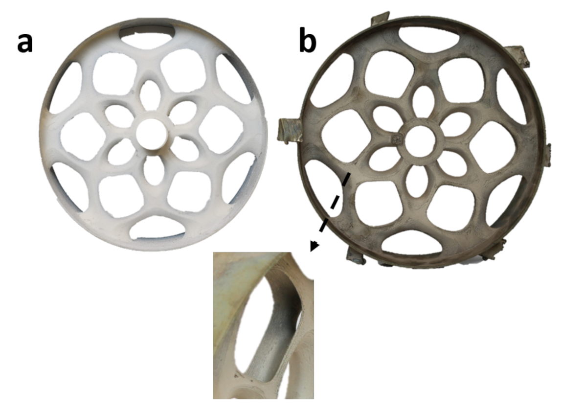
  • Successful manufacturing with hybrid additive manufacturing on a scaled rotor TPMS structure suggesting feasibility of scaling to full size using this technique.
  • The Schwartz Primitive design depicted increased strength in the torsional deflection than Gyroid or Diamond designs
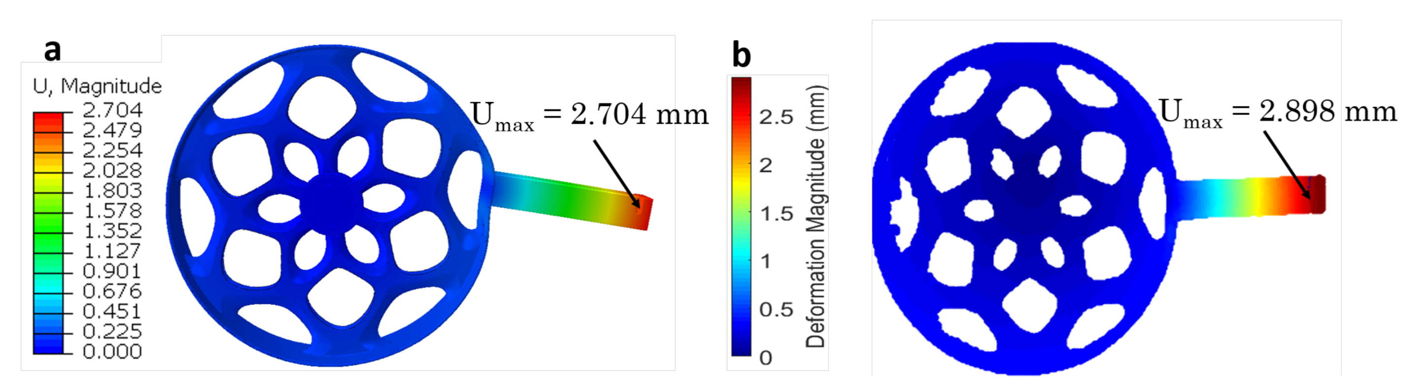
  • Experimental validation of the TPMS structure FEA model through DIC of a 3D printed Schwartz Primitive rotor model in PLA.
Implicit modeling coupled to FEA holds promise for lightweighting of large scale parts and is the focus of much research in other industries such as aerospace, automotive, and civil engineering. Limitations to this study include a lack of multi physics modeling connecting structural to thermal to electromagnetics as well as the difficulty of large scale prototyping. Nevertheless, this study represents a step toward PMDD generator mass reduction through optimized TPMS generative design of large lattice parts and hybrid additive manufacturing.

Supplementary Materials

The following are available online at https://0-www-mdpi-com.brum.beds.ac.uk/2571-8797/3/1/13/s1.

Author Contributions

Conceptualization, methodology, experimentation, and validation was performed by A.C.H. Supervision and project administraion provided by G.L.W. All authors have read and agreed to the published version of the manuscript.

Funding

This material is based upon work supported by the National Science Foundation Graduate Research Fellowship Program under Grant No. (DGE 1650115), as well as startup funds provided by the University of Colorado Boulder.

Acknowledgments

The authors thank members of the CU BEEM lab who helped in identifying problems and providing their support. The authors also thank Robert MacCurdy who provided knowledge in optimization approaches. The authors also thank Latha Sethuraman, Lee Jay Fingersh, and Katherine Dykes for their expertise and help on electric machines during a 2017 SULI internship. This material is based upon work supported by the National Science Foundation Graduate Research Fellowship Program under Grant No. (DGE 1650115), as well as startup funds provided by the University of Colorado Boulder. Any opinions, findings, and conclusions or recommendations expressed in this material are those of the authors and do not necessarily reflect the views of the National Science Foundation.

Conflicts of Interest

The authors declare no conflict of interest. The funders had no role in the design of the study; in the collection, analyses, or interpretation of data; in the writing of the manuscript, or in the decision to publish the results.

Abbreviations

The following abbreviations are used in this manuscript:
TPMSTriply Periodic Minimal Surface
FEAFinite Element Analysis
PMDDPermanent Magnet Direct Drive
AMAdditive Manufacturing
FDMFused Deposition Modeling
DMLSDirect Metal Laser Sintering
GAGenetic Algorithm
DICDigital Image Correlation
PLAPolylactic Acid

References

  1. US EIA. U.S. Energy Information Administration Annual Energy Outlook 2020; U.S. Department of Energy: Washington, DC, USA, 2020. [Google Scholar]
  2. Keller, J.; Sheng, S.; Cotrell, J.; Greco, A. Wind Turbine Drivetrain Reliability Collaborative Workshop: A Recap; National Renewable Energy Laboratory, U.S. Department of Energy: Washington, DC, USA, 2016. [Google Scholar]
  3. Mueller, M.A.; Polinder, H.; McDonald, A.S. Structural mass in direct-drive permanent magnet electrical generators. IET Renew. Power Gener. 2008, 2, 3–15. [Google Scholar]
  4. McDonald, A. Structural Analysis of Low Speed, High Torque Electrical Generators for Direct Drive Renewable Energy Converters. Ph.D. Thesis, University of Edinburgh, Edinburgh Research Archive, Edinburgh, UK, 2008. [Google Scholar]
  5. Zavvos, A.; McDonald, A.; Mueller, M. Optimisation tools for large permanent magnet generators for direct drive wind turbines. IET Renew. Power Gener. 2013, 7, 163–171. [Google Scholar] [CrossRef]
  6. Mueller, M.A.; McDonald, A.S. A lightweight low-speed permanent magnet electrical generator for direct-drive wind turbines. Wind Energy 2009, 12, 768–780. [Google Scholar] [CrossRef]
  7. Drechsler, M.; Nicholas, J. Distribution of the lattice energy in cubic crystals and its variation with compression or expansion. Solid State Commun. 1967, 5, i. [Google Scholar] [CrossRef]
  8. Hales, T.C. The Honeycomb Conjecture. Discret. Comput. Geom. 2001, 25, 1–22. [Google Scholar] [CrossRef] [Green Version]
  9. Almsherqi, Z.A.; Kohlwein, S.D.; Deng, Y. Cubic membranes: A legend beyond the Flatland* of cell membrane organization. J. Cell Biol. 2006, 173, 839–844. [Google Scholar] [CrossRef] [Green Version]
  10. Maskery, I.; Sturm, L.; Aremu, A.; Panesar, A.; Williams, C.; Tuck, C.; Wildman, R.; Ashcroft, I.; Hague, R. Insights into the mechanical properties of several triply periodic minimal surface lattice structures made by polymer additive manufacturing. Polymer 2018, 152, 62–71. [Google Scholar] [CrossRef]
  11. Giannitelli, S.; Accoto, D.; Trombetta, M.; Rainer, A. Current trends in the design of scaffolds for computer-aided tissue engineering. Acta Biomater. 2014, 10, 580–594. [Google Scholar] [CrossRef]
  12. Maconachie, T.; Tino, R.; Lozanovski, B.; Watson, M.; Jones, A.; Pandelidi, C.; Alghamdi, A.; Almalki, A.; Downing, D.; Brandt, M.; et al. The compressive behaviour of ABS gyroid lattice structures manufactured by fused deposition modelling. Int. J. Adv. Manuf. Technol. 2020, 107, 4449–4467. [Google Scholar] [CrossRef]
  13. Yánez, A.; Herrera, A.; Martel, O.; Monopoli, D.; Afonso, H. Compressive behaviour of gyroid lattice structures for human cancellous bone implant applications. Mater. Sci. Eng. C 2016, 68, 445–448. [Google Scholar] [CrossRef]
  14. Afshar, M.; Anaraki, A.P.; Montazerian, H.; Kadkhodapour, J. Additive manufacturing and mechanical characterization of graded porosity scaffolds designed based on triply periodic minimal surface architectures. J. Mech. Behav. Biomed. Mater. 2016, 62, 481–494. [Google Scholar] [CrossRef] [PubMed]
  15. Adam, G.A.; Zimmer, D. Design for Additive Manufacturing—Element transitions and aggregated structures. CIRP J. Manuf. Sci. Technol. 2014, 7, 20–28. [Google Scholar] [CrossRef]
  16. Ponche, R.; Kerbrat, O.; Mognol, P.; Hascoet, J.Y. A novel methodology of design for Additive Manufacturing applied to Additive Laser Manufacturing process. Robot. Comput. Integr. Manuf. 2014, 30, 389–398. [Google Scholar] [CrossRef] [Green Version]
  17. Yang, Z.; Yu, Y.; Wei, Y.; Huang, C. Crushing behavior of a thin-walled circular tube with internal gradient grooves fabricated by SLM 3D printing. Thin-Walled Struct. 2017, 111, 1–8. [Google Scholar] [CrossRef] [Green Version]
  18. Catchpole-Smith, S.; Sélo, R.; Davis, A.; Ashcroft, I.; Tuck, C.; Clare, A. Thermal conductivity of TPMS lattice structures manufactured via laser powder bed fusion. Addit. Manuf. 2019, 30, 100846. [Google Scholar] [CrossRef]
  19. Snyder, J.C.; Thole, K.A. Tailoring Surface Roughness Using Additive Manufacturing to Improve Internal Cooling. J. Turbomach. 2020, 142. [Google Scholar] [CrossRef]
  20. Yan, C.; Hao, L.; Hussein, A.; Bubb, S.L.; Young, P.; Raymont, D. Evaluation of light-weight AlSi10Mg periodic cellular lattice structures fabricated via direct metal laser sintering. J. Mater. Process. Technol. 2014, 214, 856–864. [Google Scholar] [CrossRef]
  21. Chen, X.; Ji, Q.; Wei, J.; Tan, H.; Yu, J.; Zhang, P.; Laude, V.; Kadic, M. Light-weight shell-lattice metamaterials for mechanical shock absorption. Int. J. Mech. Sci. 2020, 169, 105288. [Google Scholar] [CrossRef]
  22. Gümrük, R.; Mines, R. Compressive behaviour of stainless steel micro-lattice structures. Int. J. Mech. Sci. 2013, 68, 125–139. [Google Scholar] [CrossRef]
  23. Vyatskikh, A.; Delalande, S.; Kudo, A.; Zhang, X.; Portela, C.M.; Greer, J.R. Additive manufacturing of 3D nano-architected metals. Nat. Commun. 2018, 9, 1–8. [Google Scholar] [CrossRef] [Green Version]
  24. Dong, G.; Tang, Y.; Li, D.; Zhao, Y.F. Design and optimization of solid lattice hybrid structures fabricated by additive manufacturing. Addit. Manuf. 2020, 33, 101116. [Google Scholar] [CrossRef]
  25. Panesar, A.; Abdi, M.; Hickman, D.; Ashcroft, I. Strategies for functionally graded lattice structures derived using topology optimisation for Additive Manufacturing. Addit. Manuf. 2018, 19, 81–94. [Google Scholar] [CrossRef]
  26. Haertel, J.H.; Nellis, G.F. A fully developed flow thermofluid model for topology optimization of 3D-printed air-cooled heat exchangers. Appl. Therm. Eng. 2017, 119, 10–24. [Google Scholar] [CrossRef] [Green Version]
  27. Awd, M.; Tenkamp, J.; Hirtler, M.; Siddique, S.; Bambach, M.; Walther, F. Comparison of Microstructure and Mechanical Properties of Scalmalloy® Produced by Selective Laser Melting and Laser Metal Deposition. Materials 2018, 11, 17. [Google Scholar] [CrossRef] [Green Version]
  28. Gokuldoss, P.K.; Kolla, S.; Eckert, J. Additive Manufacturing Processes: Selective Laser Melting, Electron Beam Melting and Binder Jetting—Selection Guidelines. Materials 2017, 10, 672. [Google Scholar] [CrossRef] [PubMed] [Green Version]
  29. Milad, S.Y.; Latifi Rostami, S.; Kolahdooz, A. Optimization of geometrical parameters in a specific composite lattice structure using neural networks and ABC algorithm. J. Mech. Sci. Technol. 2016, 30, 1763–1771. [Google Scholar]
  30. Chen, J.; Yang, R.; Ma, R.; Li, J. Design optimization of wind turbine tower with lattice-tubular hybrid structure using particle swarm algorithm. Struct. Des. Tall Spec. Build. 2016, 25, 743–758. [Google Scholar] [CrossRef]
  31. Bendsøe, M.P.; Kikuchi, N. Generating optimal topologies in structural design using a homogenization method. Comput. Methods Appl. Mech. Eng. 1988, 71, 197–224. [Google Scholar] [CrossRef]
  32. Bendsøe, M.P. Optimal shape design as a material distribution problem. Struct. Optim. 1989, 1, 193–202. [Google Scholar] [CrossRef]
  33. Sigmund, O. A 99 line topology optimization code written in Matlab. Struct. Multidiscip. Optim. 2014, 21, 120–127. [Google Scholar] [CrossRef]
  34. Plocher, J.; Panesar, A. Review on design and structural optimisation in additive manufacturing: Towards next-generation lightweight structures. Mater. Des. 2019, 183, 108164. [Google Scholar] [CrossRef]
  35. Daynes, S.; Feih, S.; Lu, W.F.; Wei, J. Design concepts for generating optimised lattice structures aligned with strain trajectories. Comput. Methods Appl. Mech. Eng. 2019, 354, 689–705. [Google Scholar] [CrossRef]
  36. Sethuraman, L.; Dykes, K. GeneratorSE: A Sizing Tool for Variable-Speed Wind Turbine Generators; Technical report NREL/TP -5000-66462; National Renewable Energy Laboratory: Golden, CO, USA, 2017. Available online: https://www.nrel.gov/docs/fy17osti/66462.pdf (accessed on 1 October 2020).
  37. nTopology. nTopology Introduces nTop Platform 2.0. Available online: https://ntopology.com (accessed on 12 September 2020).
  38. Smith, M. ABAQUS/Standard User’s Manual; Version 6.9; Dassault Systèmes Simulia Corp: Johnston, RI, USA, 2009. [Google Scholar]
  39. GE Additive. Arcam EBS Spectra L. 2020. Available online: https://www.ge.com/additive/additive-manufacturing/machines/arcam-ebm-spectra-l (accessed on 12 September 2020).
  40. GE Additive. GE Additive creates world’s largest laser-powder 3D printer. Met. Powder Rep. 2017, 72, 367. [Google Scholar] [CrossRef]
  41. Art Castings of Colorado. Rotor Casts ACC. 2020. Available online: https://www.artcastings.com (accessed on 12 September 2020).
  42. DZ Turner. Digital Image Correlation Engine (DICe) Reference Manual, Sandia Report; SAND2015-10606 O; U.S. Department of Energy: Washington, DC, USA, 2015.
  43. Hayes, A.C.; Sethuraman, L.; Fingersh, L.J.; Dykes, K. Additive Manufacturing: A New Paradigm for the Next Generation of High-Power-Density Direct-Drive Electric Generators. In Proceedings of the ASME Power Conference, Lake Buena Vista, FL, USA, 24 June 2018; Volume 2. [Google Scholar] [CrossRef] [Green Version]
  44. Sivarupan, T.; Upadhyay, M.; Ali, Y.; El Mansori, M.; Dargusch, M.S. Reduced consumption of materials and hazardous chemicals for energy efficient production of metal parts through 3D printing of sand molds. J. Clean. Prod. 2019, 224, 411–420. [Google Scholar] [CrossRef]
  45. Lamichhane, T.; Sethuraman, L.; Dalagan, A.; Wang, H.; Keller, J.; Paranthaman, M. Additive manufacturing of soft magnets for electrical machines—A review. Mater. Today Phys. 2020, 15, 100255. [Google Scholar] [CrossRef]
Figure 1. (a) B-rep representation of a torus (b) Implicit modeling of a torus as a signed distance field where F < 0 indicates part, F = 0 indicates boundary, F > 0 indicates void.
Cleantechnol 03 00013 g001
Figure 2. Structural loads of a 5 MW Radial Flux PMDD machine with critical limits.
Cleantechnol 03 00013 g002
Figure 3. Flow chart depicting genetic algorithm procedure.
Cleantechnol 03 00013 g003
Figure 4. (a) Optimization scheme combining FEA and lattice generation with genetic algorithm (b) Visualization of three lattice types used in implicit optimization.
Cleantechnol 03 00013 g004
Figure 5. (a) Lattice parameters used in minimal surface optimization (b) Parameters used in functionally graded lattice optimization.
Cleantechnol 03 00013 g005
Figure 6. Results of TPMS parameter optimization (a) Top view of Diamond rotor (b) Side view of Diamond rotor (c) Top view of Schwartz Primitive rotor (d) Side view of Schwartz Primitive rotor (e) Top view of Gyroid rotor (f) Side view of Gyroid rotor (g) Tabulated Results of TPMS parameter optimization.
Cleantechnol 03 00013 g006
Figure 7. Results of TPMS functionally graded lattice optimization with color map depicting gradient lattice thickness (a) Diamond rotor TPMS design with strain field thickness (b) Schwartz Primitive rotor TPMS design with strain field thickness (c) Gyroid rotor TPMS design with strain field thickness (d) Tabulated results from functionally graded lattice rotor optimization.
Cleantechnol 03 00013 g007
Figure 8. Functionally graded lattice optimization results with dotted line at critical values (a) Inactive Mass of all designs (b) Radial deformation of all designs (c) Torsional deformation of all designs.
Cleantechnol 03 00013 g008
Figure 9. (a) Polycast FDM printed Schwartz Primitive rotor (b) Bronze cast Schwartz Primitive rotor.
Cleantechnol 03 00013 g009
Figure 10. (a) Abaqus simulated DIC loading conditions deflection magnitude (b) DIC deflection magnitude with weighted torque arm.
Cleantechnol 03 00013 g010
Table 1. Large scale AM techniques and associated printing time and mass for scaled Schwartz Primitive rotors.
AM MethodPossible Part
Dimensions (m)
Cost ($)Part Resolution (m)Estimated Print Time (hrs)Schwartz P Scaled Rotor Weight (mT)
0.03 MW1 MW3 MW5 MW0.03 MW1 MW3 MW5 MW
DMLS [39]0–0.5$$$100160.012.4812.9327.72
Investment Casting Wax Printed Part [41]0–3$$5006 weeks6 weeks
Powder Binder Jetting Sand Casting [44]3–10$100080.9105
Publisher’s Note: MDPI stays neutral with regard to jurisdictional claims in published maps and institutional affiliations.

