Case Report

A Multidisciplinary Conservation Project for the Cavallerizza Courtyard, Palazzo Ducale di Mantova

1
Dept. ABC (Architecture, Built Environment and construction engineering), Politecnico di Milano, Via Ponzio 31, 20133 Milano, Italy
2
Segretariato Regionale del Ministero per i beni e le attività culturali per la Lombardia, Palazzo Litta-Corso Magenta 24, 20123 Milano, Italy
3
Complesso Museale di Palazzo Ducale di Mantova, Piazza Sordello 40, 46100 Mantova, Italy
4
Dept. DICATAM (Department of Civil, Environmental, Architectural Engineering and Mathematics), Università degli Studi di Brescia, Via Branze 43, 25100 Brescia, Italy
*
Authors to whom correspondence should be addressed.
Submission received: 1 April 2019 / Revised: 29 April 2019 / Accepted: 13 May 2019 / Published: 16 May 2019

Abstract

:
The “Palazzo Ducale” museum complex in Mantua has been the object of intermittent interventions, which have not represented, over the last 30 years, a consistent strategy in terms of conservation. In the light of new financial and technological possibilities, a renewed management synergy has been activated: better operative decisions and the application of innovative tools are the core of this attitude. The article illustrates the path of knowledge activated in the museum’s “Cortile della Cavallerizza”: from archival research, geometrical survey and diagnostic analysis, up to the executive design of its conservative project.

1. Introduction

The Palazzo Ducale complex of Mantua has been classified by d.m. 23/12/2014 (a ministerial decree regarding museums) amongst the autonomous national museums, which has been an important opportunity for taking care of the architectural complex. This has favoured a renewed process of management of its functions and of interventions in its built heritage. The interventions executed on the monument over the last 30 years have not followed a consistent conservation strategy. Direct observations of the complex and appraisals by the superintendents have shown how these operations were determined by the urgent needs of a particular time, and therefore were limited to occasional and partial actions. The availability of financial resources has activated a management synergy for new projects, supporting restoration activities research with the application of innovative technologies. This article aims to illustrate the knowledge acquisition process in the courtyard of the Cavallerizza, inside the museum complex, up to the executive design of the conservation project.

2. The Evolution of the Building

Palazzo Ducale (Figure 1) presents a varied historical and architectural stratification, strongly linked to the city life. The Gonzagas settled in Mantua from 1328 [1].
The Gonzaga [2] family promoted Renaissance culture through the contribution of important architects and painters who expressed their art within the Palazzo. With Ludovico II (1444–1478), Mantua became one of the most relevant centres of the Renaissance, giving hospitality to great artists such as Leon Battista Alberti, Luca Fancelli and Andrea Mantegna. During those years the Castle of San Giorgio and the surrounding areas became the core of the palace. Refurbishment work took place in some rooms, to accommodate the Duke’s apartment, where Mantegna painted his famous “Camera picta”.
During the short regency of Federico I (1478–1484), the “Domus Nova” was started by Fancelli.
His successor, Francesco II (1484–1519), dedicated himself to some works in the Castle such as the layout of his apartment and that of his wife Isabella d”Este. The growth in fame of Mantua was advanced by Isabella who, as an educated and refined patron, enriched the palace with valuable decorations and collections.
Federico II (1519–1540), son of Francesco II and Isabella d’Este, was given the title of Duke by Emperor Charles V in 1530, and began works in the Castello and Corte Nuova, having started in 1524 a collaboration with Giulio Romano, pupil of Raffaello Sanzio.
Giulio Romano built the “Palazzina della Paleologa” for Margherita Paleologa, wife of Federico II, and started the refurbishment of one of the castle’s ravelins [3].
His successor, Guglielmo Gonzaga (1550–1587), was responsible for the regularization of the spaces and the connection between the apartments of the Palace [4]. He started the renovation of the Palace and in particular the “Mostra” (currently called the “Cavallerizza” garden) [5]. The managers of these works were the architects Giovan Battista Bertani and Bernardino Facciotto [6].
From 1536 the works began on the Rustica (Figure 2), the southeastern front of the Cortile della Cavallerizza.
Despite the apparent homogeneity of the courtyard, each elevation shows independence of construction in terms of thought, organization, materials and processing techniques. Only when all sides are made is an attempt made to unify the design, achieving the current result.
From the archival documents emerges a strong sharing of ideas between the Duke and Giulio Romano. The Duke always wanted to be informed about the construction activities despite the trust he placed in the architect. The concerns expressed about structural problems, difficulties in water management, etc., are significant.
The collaboration between the architect and the client solves problems. In particular, Giulio Romano’s ‘trick’ is brilliant and created the opportunity to use the water to create fountains and water games in the court [7].
The “Galleria dei Marmi” (Figure 3) is the second front conceived by Giulio Romano.
The work of adapting the spaces is interesting. The spans are not regular but their succession does not emerge from the dimensional differences necessary to give a proper solution corner. If in the Rustica the solomonic columns emerge from a solid rusticated wall, here they flank the arches of the original Loggia. Compared to the seven arches of the Rustica, here there are eight. It is interesting to note the difference in height between the floor elevations of the Gallery of the Marbles and the “Galleria della Mostra” (Gallery of the Exhibition): if it corresponds to the level of the windowsill for the former, it equals the floor level for the latter [7]. In the “Galleria della Mostra”, after the death of Giulio Romano, the architect Bertani tried to introduce different solutions from those conceived by Giulio Romano [8]. However, not the archival data but the information obtained in the restoration of the early 20th century have clarified the construction (Figure 4) [9].
The “Corridore” is the front that closes the court. Our observations provide interesting information on its construction (Figure 5). The direct examination (on the occasion of the first restoration) of the masonry confirms the hypothesis that the new loggia was being added to the existing city walls. The pillars of the external side of the portico have been obtained “by subtraction”, that is, by demolishing the thickness of the wall. In the demolition, arches were obtained. On the contrary, the inner side of the porch is completely new. From the outside of the courtyard the anchoring ties are evident, positioned to weld the two parts into a single resistant element.
The documentation of the restoration work was particularly useful for setting up the conservation project. Within the logic of Programmed Conservation, as our work is intended to be, knowledge of modern restoration work plays a fundamental role. Also, the information preserved through a photographic documentation allowed us to georeference the interventions carried out and to know in detail the materials used in the restoration.
From 1866 the conservation status of the Cavallerizza was monitored with greater precision. Achille Patricolo was the curator of the building.
Despite the attention and the desire to reorganize the management of the building promoted by Patricolo, in 1908 the Cortile della Mostra was used as a tennis court, with negative consequences on the decorative apparatus because of such improper use. Attempts to give continuity to the maintenance were hindered by circumstances rather than by the will of those responsible.
Alfredo Barbacci (responsible from 1936 to 1939) offered an interesting statement on the conservation status of the Cortile della Cavallerizza. The architect described its precarious conservation conditions due to the use of the internal garden as a vegetable garden. In particular, Barbacci underlined how the plasticity of the rustication was decidedly compromised and the colours almost invisible.
A first construction site led by Barbacci began in 1936 and concerned the Rustica elevation. It is interesting that he observed how the plastic ornaments were still present but detached from the wall support (Barbacci, 1939).
The operational choice proposed by Barbacci was to consolidate them with injections of “liquid mortar”. The missing plaster and ashlars were reintegrated in imitation of the originals (by giving them an antiqued effect). Only for the Solomonic columns did Barbacci propose a non-imitative approach, as demonstrated by the fact that the decorations simulating vine shoots were not re-proposed but the surface was kept smooth.
The last “unitary” construction (that is, managed with the same criteria of intervention) took place between 1937 and 1938 and concerns the Corridore towards the lake; the infills of the ground floor arches were demolished and the railings placed. Even on this side the ashlars were “integrated”, such as the plaster on the first and second order.
Barbacci also described the original colours of the ashlar: slightly muted yellow, red and grey. Only in the 1980s were new interventions on the external surfaces implemented, with projects that were consistent with the peculiarities of the place. That projects drafted by the Superintendency of Brescia. Unfortunately, from the surveys stored in the archive, it is not always possible to identify precisely the areas of intervention, because the drawings accompanying the appraisals are generic and do not clarify whether the described procedure has been uniformly performed. A second period of work on the surfaces began in 1994, on the initiative of Ruggero Boschi, Superintendent for environmental and architectural assets for Mantova Brescia and Cremona. This last project was a turning point in the management of the built environment, agreeing with present-day positions on the matter. Among the documents, there is a certificate of the chemical‒physical investigations aimed at identifying the materials present. The techniques and degradation factors are also indicated.
The appraisal envisaged (as an intervention rule) wet cleaning with a nebuliser (AB-57) or localized aeroabrasives. For consolidating, Primal AC-33 (Perugia, Italy) diluted in demineralized water was used. The reconstruction of the ashlars was done with a mixture of lime, aggregates and pigments with slightly subdued colours compared to those detected. The entire surface was then treated with a water-repellent final protective layer.

3. Preliminary Analysis

The conservation project is the result of a collaboration between the Complesso Museale di Palazzo Ducale di Mantova, the He.Su.Tech group of Mantovalab of the Politecnico di Mantova, and the Centro per la Conservazione e il Restauro dei Beni Culturali “La Venaria Reale”.
Each institution provided its own skills.

3.1. The Survey

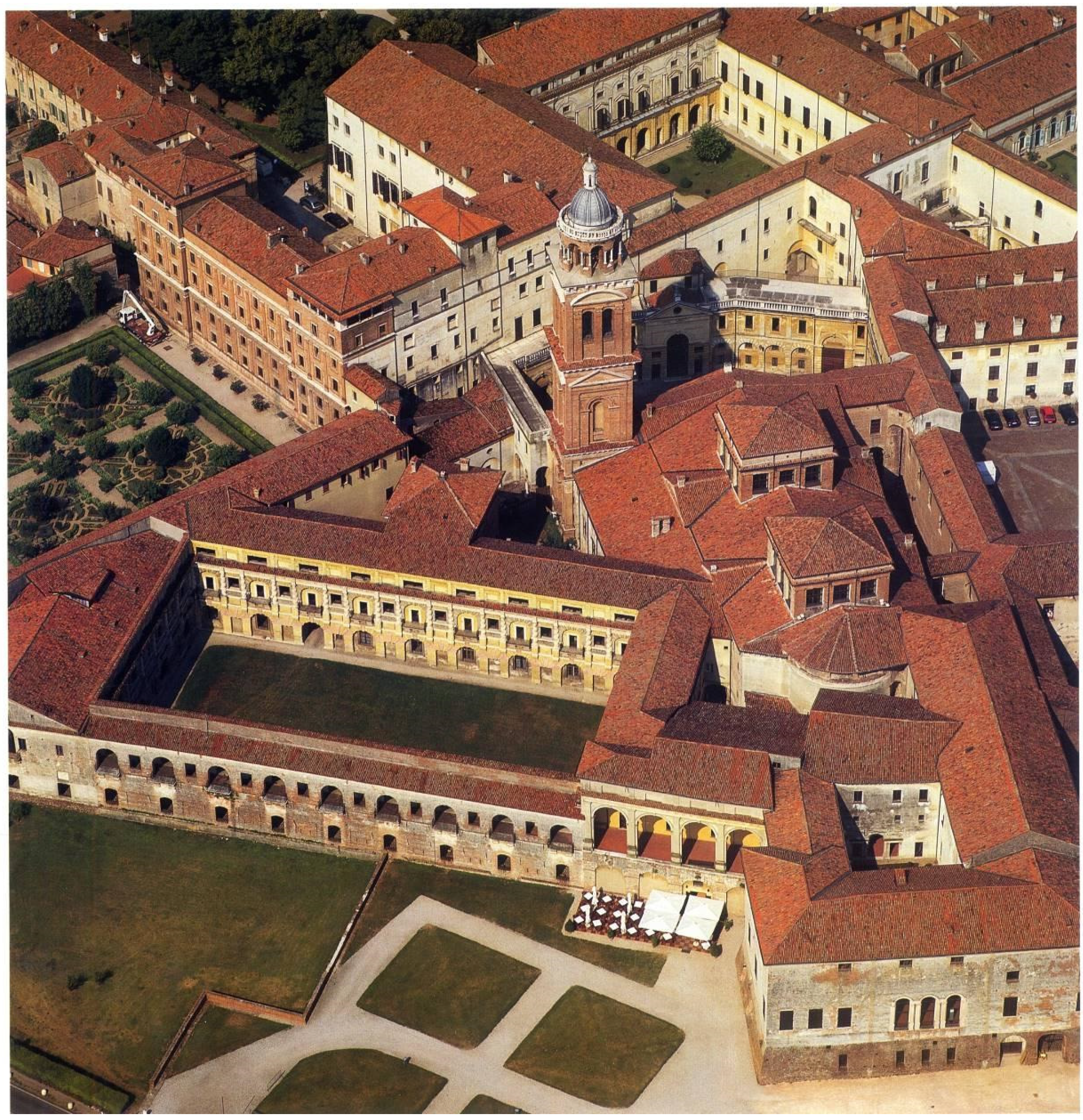
To guarantee a more extensive knowledge of the Cortile della Cavallerizza and its connected parts, a survey was carried out through the integration of the most recent methodologies and instruments in the field of geomatics.
The survey phase has followed the general principle that characterizes the geomatic discipline, a top-down approach that requires one to start from the general and then move to details. The framework of the survey is, as in best practice, made up of a topographic network that not only materializes the reference system (unique for the entire complex to be surveyed) but facilitates the integration of different methods. The network is the skeleton of the whole survey to which all the other surveyed elements are directly connected and referred. The materialization of the topography was the first task to complete following the top-down methodology described: it was framed in the national reference system IGM95 thanks to the acquisition of two national Ground control point (one in Piazza Sordello and the second on the lake shore). This structuring allows at any time the integration of new information acquired at different times and stages and ensures comparison with the national cartographic products.
Detailed topographic acquisitions for the survey of the architectural complex followed, where observations were made starting from the principal points of the network, to support the photogrammetric and laser scanning surveys. Generally, the points surveyed with a Leica Geosystems AG—Part of Hexagon, Huntsville, [AL], USA TC30 total station were the black and white chess target (for the registration of the laser data) and the code markers (for the photogrammetric phase). The results obtained after the least square adjustment (the coordinates of the points) have an average standard deviation of less than ±1 mm and are therefore suitable for the 1:50 scale survey of the entire complex of the Cavallerizza.
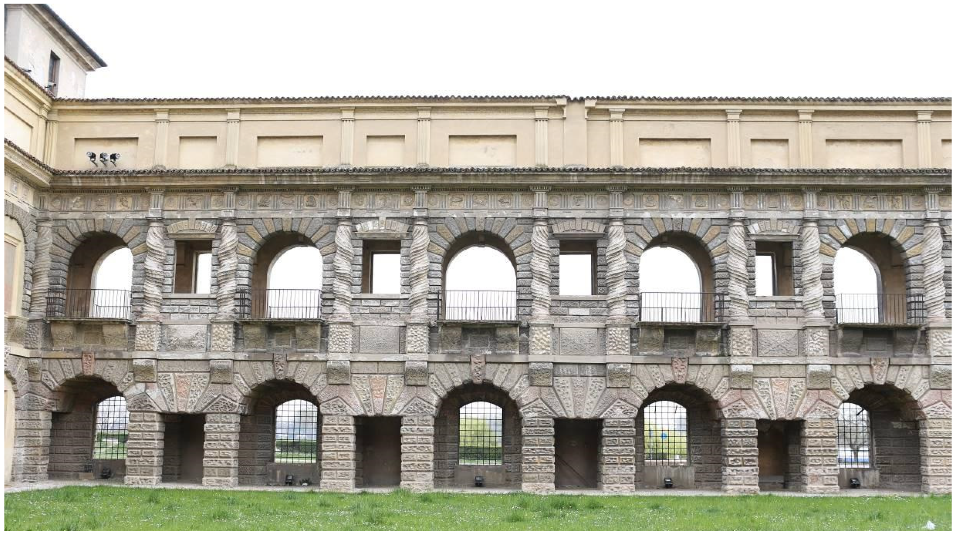
In the survey of the courtyard (including the wall surfaces and the gallery) it was decided to integrate laser scanner with photogrammetry (Figure 6) in order to have a complete dataset that met both the needs of a geometric description of the building (for the architectural survey) and its qualitative description, from which to extract information related to the materials used and the state of preservation.
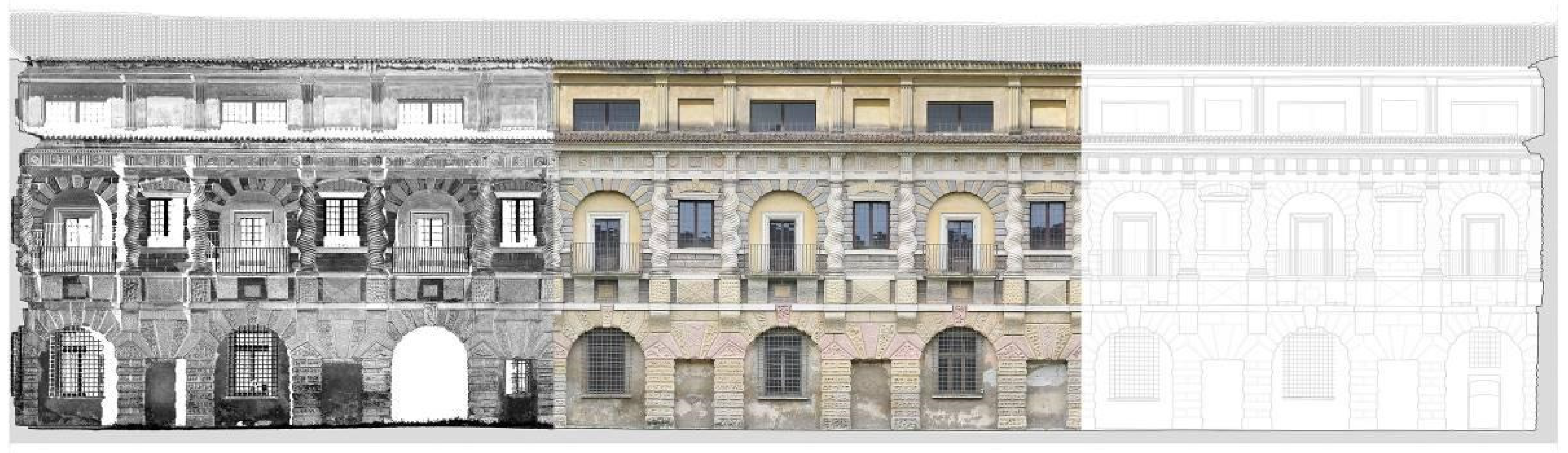
The laser scanner survey was carried out by the phase shift Leica HDS 7000, and made it possible to describe the interior of the courtyard, as well as the Corridore passing through it and the exterior facing the lake (Figure 7). A total of 26 scans were taken, on several levels and from different positions, setting the resolution to an average value of 3 m at a 10 m distance to ensure a density of points suitable for the scale of representation 1:50 (in fact, given the overlap of data, the database of point clouds also became suitable for the extraction of drawings at the 1:20 scale). The scans were georeferenced in Leica Cyclone software using the coordinates of the targets measured with topography. At the end of the acquisition phase, a single database was created, and, through Autodesk Recap, San Rafael, [CA], USA, the data were imported into the Autocad environment and digitized.
Simultaneous to the laser scanner survey, a photogrammetric campaign was carried out, based on “structure from motion” and “dense stereo matching” algorithms. To obtain the best results, a high-resolution camera Canon, Tokyo, Japan Mark III was used with different lenses (24 mm, 35 mm and 85 mm). The different lenses allowed us to maintain for each element of the site (facades, ceilings and vaults) an average GSD of less than 1 mm in order to process the photogrammetric products with a final real pixel size of 5 mm.
The acquisitions were made following the logic of the photogrammetric strip, but with a longitudinal and transversal overlap of about 70–80% to allow greater recognition of significant points to be used in the orientation phase. In addition to the frames normal to the facade, used in the strip, frames with an inclined axis were acquired, with the aim of stiffening the acquired geometry; this was also dictated by the elongated and homogeneous geometric shape of the building itself, which could have led to drift effects. Also, in the case of photogrammetry, targets (encoded by the software Agisoft Photoscan St. Petersburg, Russia—now Metashape) were acquired by topographic means that allowed us to georeference the photogrammetric model in the same system. The photographic acquisition was carried out on several levels to try to overcome the undercuts caused by the rustication and decorative elements; the photos acquired are of the Exhibition Gallery, the Galleria dei Mesi, and by the Corridore (the lakeshore Loggia) that separates the courtyard from the lake.
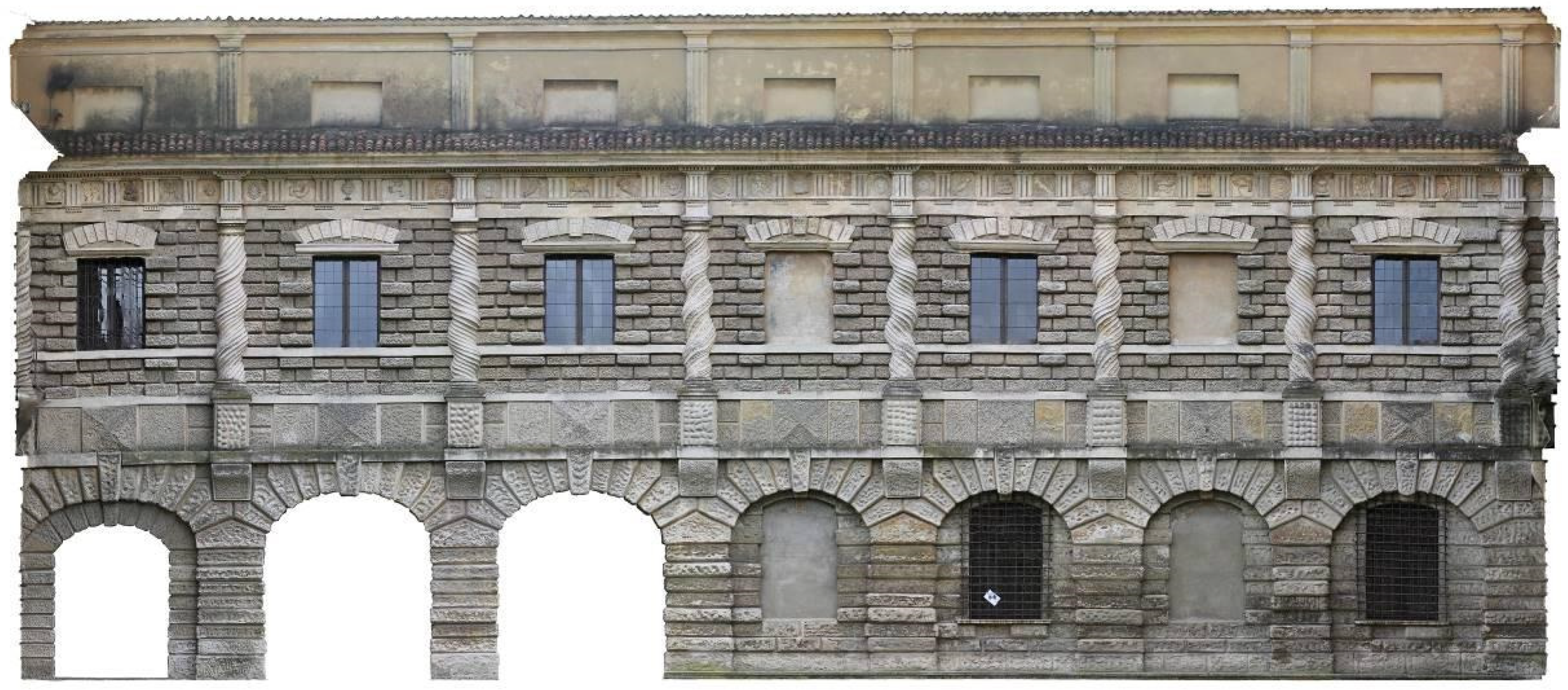
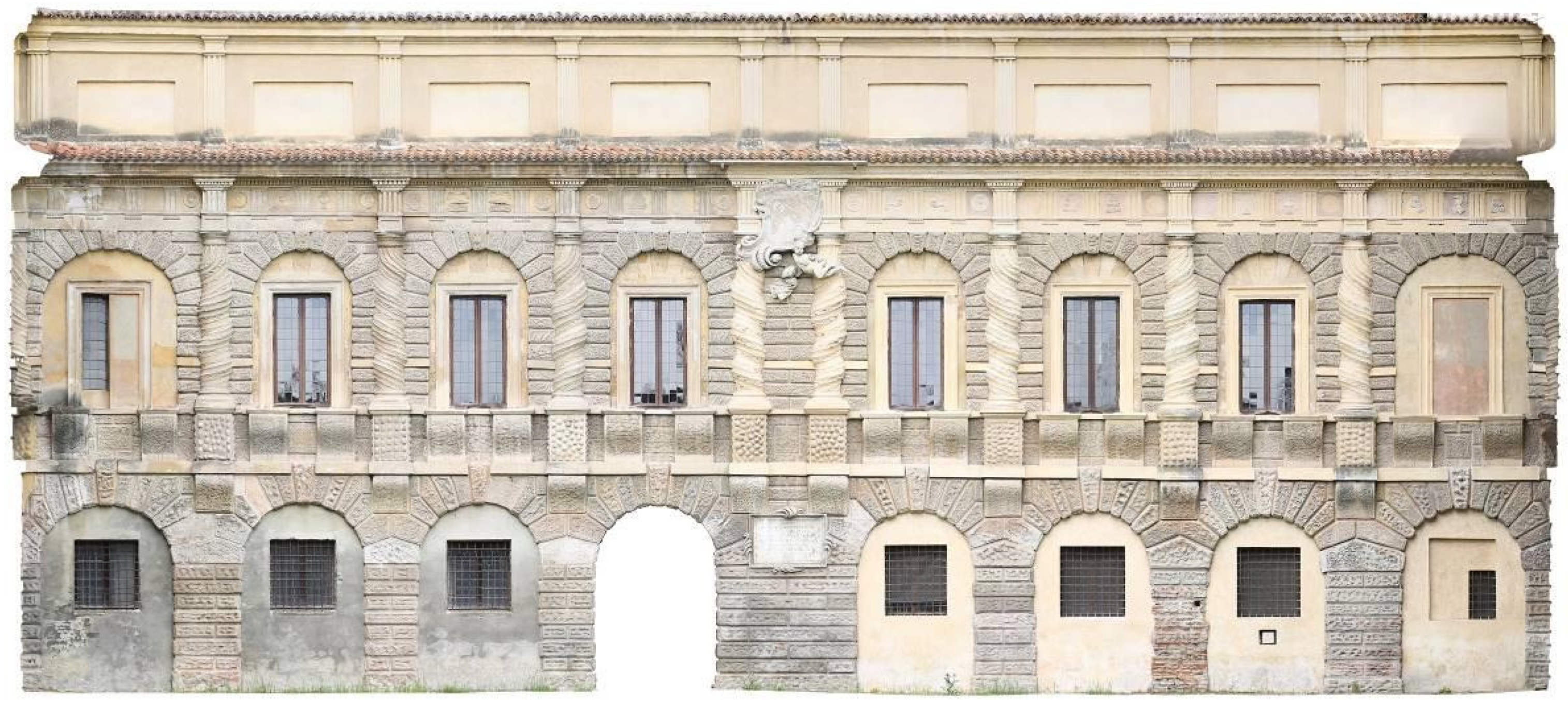
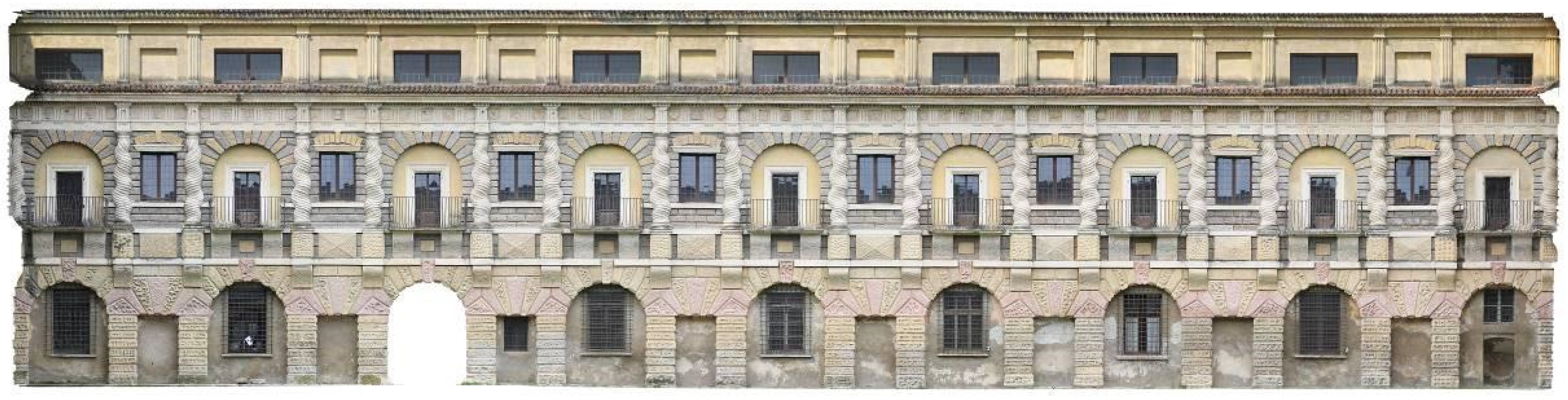
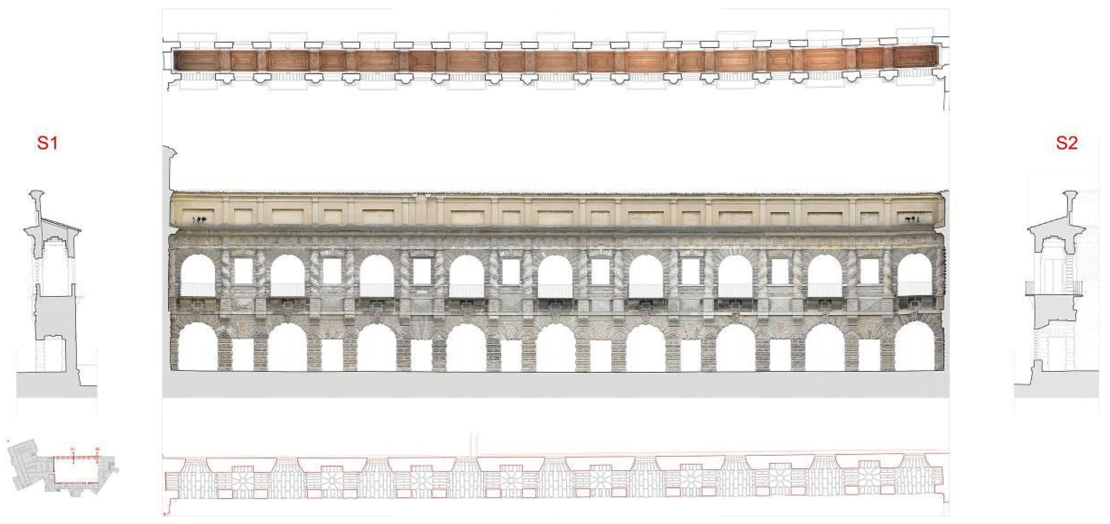
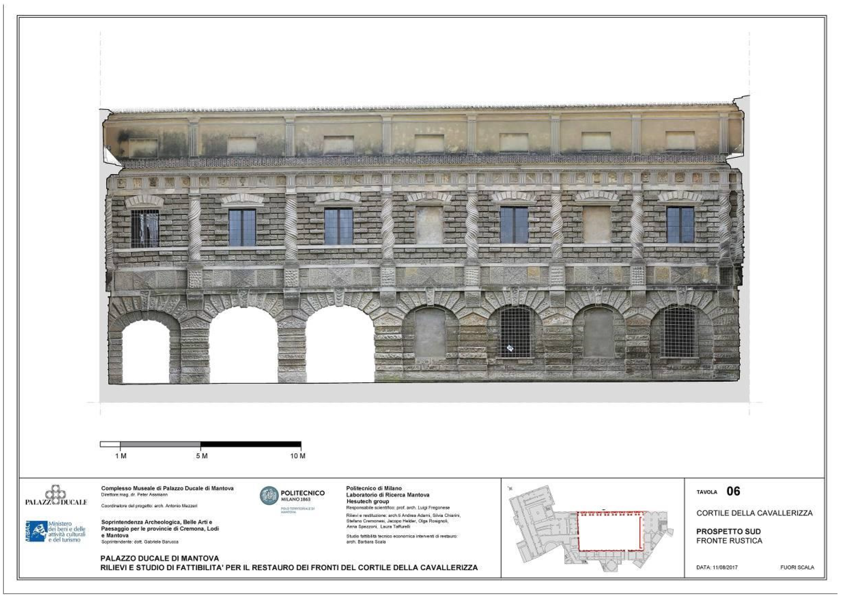
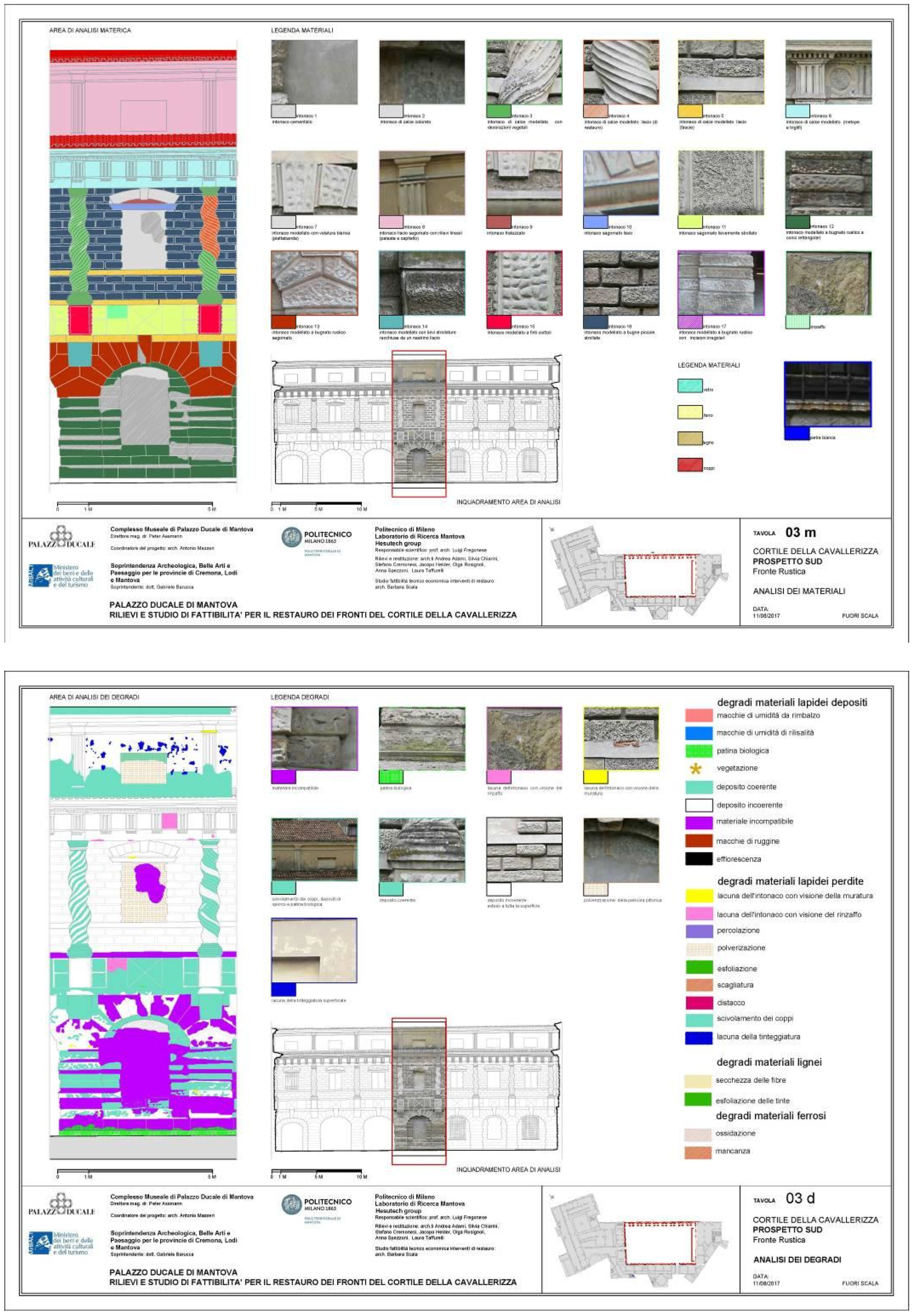
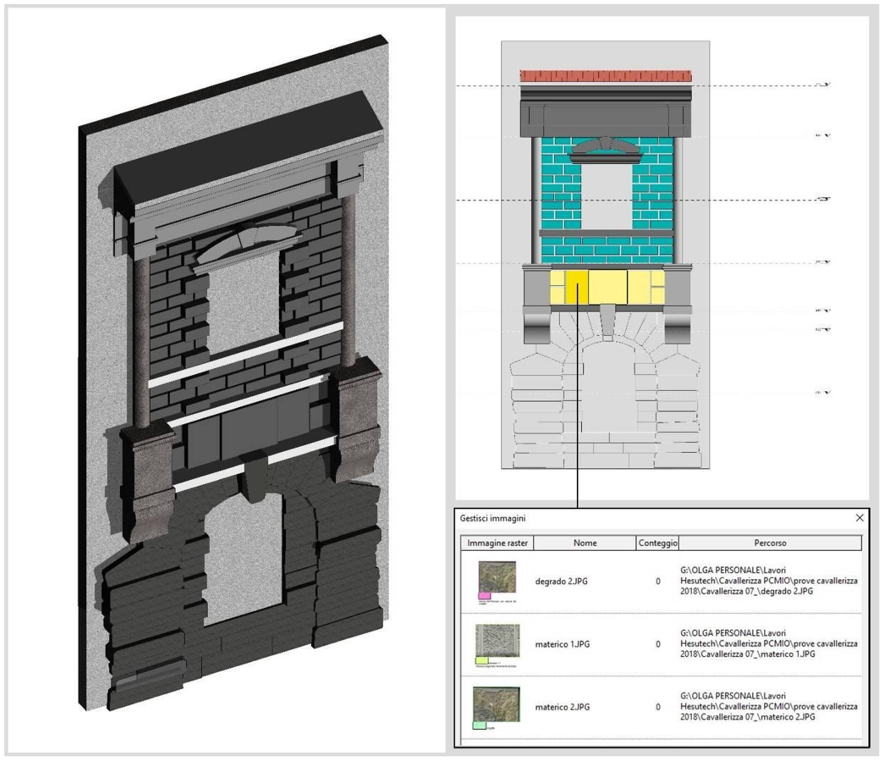
At the end of the acquisition phase, all the data (as mentioned above, included in a single georeferenced database) were imported in the Autocad environment and the design was carried out at a scale of 1:50 (Figure 8). At the same time, the orthophotos of the facades (internal and external) and of the false ceilings of the Lakeshore Loggia (Figure 7) were also processed, not only to obtain a product to be used in the geometric description of the factory, but also to support the analysis of the materials and degradation.
The processing thus obtained allowed the comparison of technological and decorative elements, leading to an interpretation of the complex based not only on archival documents, but also on the continuous material feedback of what is highlighted in the papers.
The survey carried out revealed the numerous details of both the individual fronts and, in particular, the individual technological elements. We considered it very significant to highlight these singularities because a conservation project aims precisely to preserve diversity, highlighting the solutions that are expressions of construction practice. The analysis being carried out at an autopsy level, which highlighted the wealth of construction and restoration solutions, was why chemical‒physical studies were carried out.
In order to optimize indirect investigations, direct reconnaissance has optimized the time involved, helped to confirm hypotheses and opened up new avenues of investigation.
The first aspect investigated concerns the rustication, the finishing solution that offers unity to the courtyard of the Cavallerizza and at the same time is the technique with many finishing solutions.
Four different types of finishing are visible along the pillars that support the arches:
  • rustication made with solid bricks in which the irregular shape of the surface is given by the thickness of the mortar properly engraved and worked;
  • rustication made from solid bricks in which the irregular shape of the surface is given by roof-tile fragments covered with lime mortar;
  • rustication made from solid bricks in which the irregular shape of the surface is given by fragments and flakes of brick covered with lime mortar.
  • ashlars made of solid bricks in which the shape of the surface is given by the sinuous shape of the bricks (s-shaped).
During the restorations, other types of rustication, similar to the first model, yet realized with cement mortar and with non-repeated random shapes, were performed.
On the ground floor, at the springer of the arch, there are three other types of rustication:
  • ashlars with a very irregular finish (placed on the top of the pillars as a springer of the arches);
  • ashlars with irregularities about one centimetre deep (placed to form the arc).
  • ashlars with small irregularly distributed holes (the small holes were probably made with iron or wood punches) to enrich the heterogeneity of the finish (placed between the arches and the frame along different sides).
It should be noted that both the surface treatment of the mortar and the juxtaposition of the ashlars present differences between the parts attributed to Giulio Romano and those referable to Bertani. Some gaps in the south elevation allow us to investigate the executive technique used by the workers under the guidance of Giulio Romano. On this front, the combination of bricks and the use of larger fragments in the upper part of the ashlar is visible.
Another element of differentiation between the work of the two masters is in the plaster processing.
These differences are determined by the type of effect sought:
  • a bocciarda, to obtain rounded depths of variegated dimensions
  • a serpentina, to draw tracks between the holes created with the bocciarda.
In the spans attributed to Giulio Romano’s workshop, the ashlars show a more decorative style. We can find ashlars worked alternately with a fine bocciarda technique and ashlars worked with a coarser style (Figure 9).
In the spans of the northern elevation attributed to the Giovan Battista Bertani construction phase, different workmanship is highlighted, characterized by a more pronounced chiaroscuro effect and the concomitant use of serpentina and bocciarda.
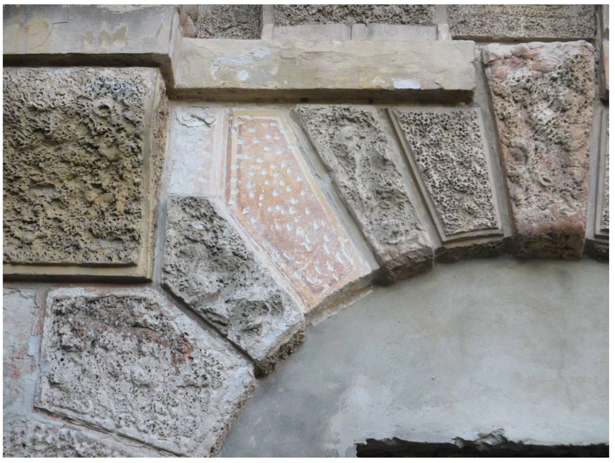
An interesting detail is a false ashlar painted on the plaster in the north elevation, on which a subsequent mortar ashlar was then applied. The plaster finish was tapped on the decorated surface to ensure the adhesion of such superficial ashlar (Figure 10).
The string-course frame is formed by quadrangular panels, slightly protruding. To give movement to the panels, small holes were carved, similar to those on the lower ashlars. For the completion of this frame the bases of the twisted columns are characterized by a fake pebble finish. Each base is an element in itself; the number and distribution of the pebbles is apparently random.
On the main floor, adjacent to the Solomonic columns, the ashlars offer formal solutions, similar to those illustrated up until now.
The greatest diversification is found in their greater or lesser projection and by the presence of the perimetral ribbon.
In particular, the northern façade presents ashlars with a rectangular and regular shape, while the south façade shows, in the vicinity of the openings, thicker ashlars, projecting towards the courtyard. While the former were treated during the last restoration with yellow and grey finishing colours, the latter are exclusively in grey.
Other ashlars used to decorate the tympanums above the windows of the first floor have a different plaster processing on both the façade realized by Giulio Romano and that of Bertani. Elements in worked mortar have also been used to fill the spaces between the bases of the columns with quadrangular panels and a diamond-point element. Moreover, the ones on the sides of the windows are arranged in staggered rows so that some of the blocks come out from the background wall.
The data on the ashlars’ mortars reveal a correspondence between the composition and granulometry of the aggregates, suggesting a continuity between the phase of Giulio Romano and that of Giovan Battista Bertani.
The mortars are constituted by an aerial lime enriched with a carbonate and, in smaller quantities, silicate aggregate. This mortar forms the ashlar plaster on which a coating has been applied in an imitation of coloured stones.
In the case of ashlar, colour has the function of emphasizing the frame made by an alternation of yellow-red or grey-yellow ashlars, which are reminiscent of the coloured stones used in the Mantuan constructions.
Clear traces of green polychromy are observed in the ashlars of the Rustica. On top of this coating, traces of a further (more recent) yellow layer were found.
In the remaining façades, the ashlars have a polychromy that alternates red and yellow. In the western elevation, in particular, the stratigraphy comprises three levels:
  • the first consists of a dark red colour, partially preserved;
  • the second, a red tint applied generically to the whole surface, is based on white with ochre and/or red earth;
  • the third is light pink and applied in a localized way.
The yellow ashlars consist of two layers, a dark yellow in the background and a lighter one in the front. It is possible that the two bottom layers are the result of the same intervention, during which two different shades would have been used.
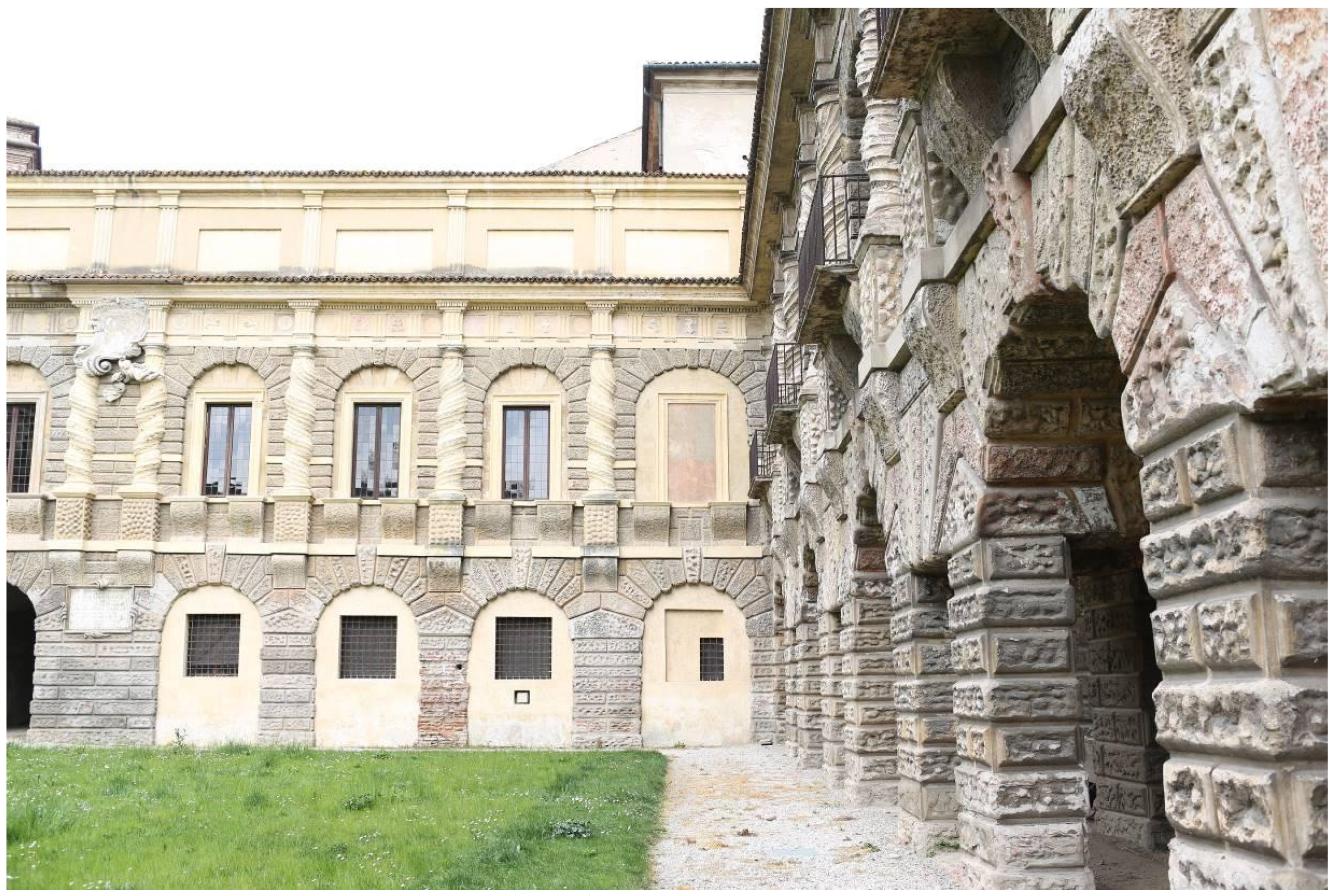
The layout of the elevations in the noble floor is marked by the iconic Solomonic columns (Figure 11).
The role of the columns is to define the subdivision of the spans, which, contrary to what appears at first glance, is irregular, not only between different fronts but also within the same front.
The base level of the columns is clearly not the same on all four sides. Along the northern front, they are set at the level of the windowsill; on the other sides, the columns lay out the entire noble floor, starting from the level of the indoor pavement. The decorative trick guaranteed by the twisting distracts the observer from the geometric irregularity of the span pace.
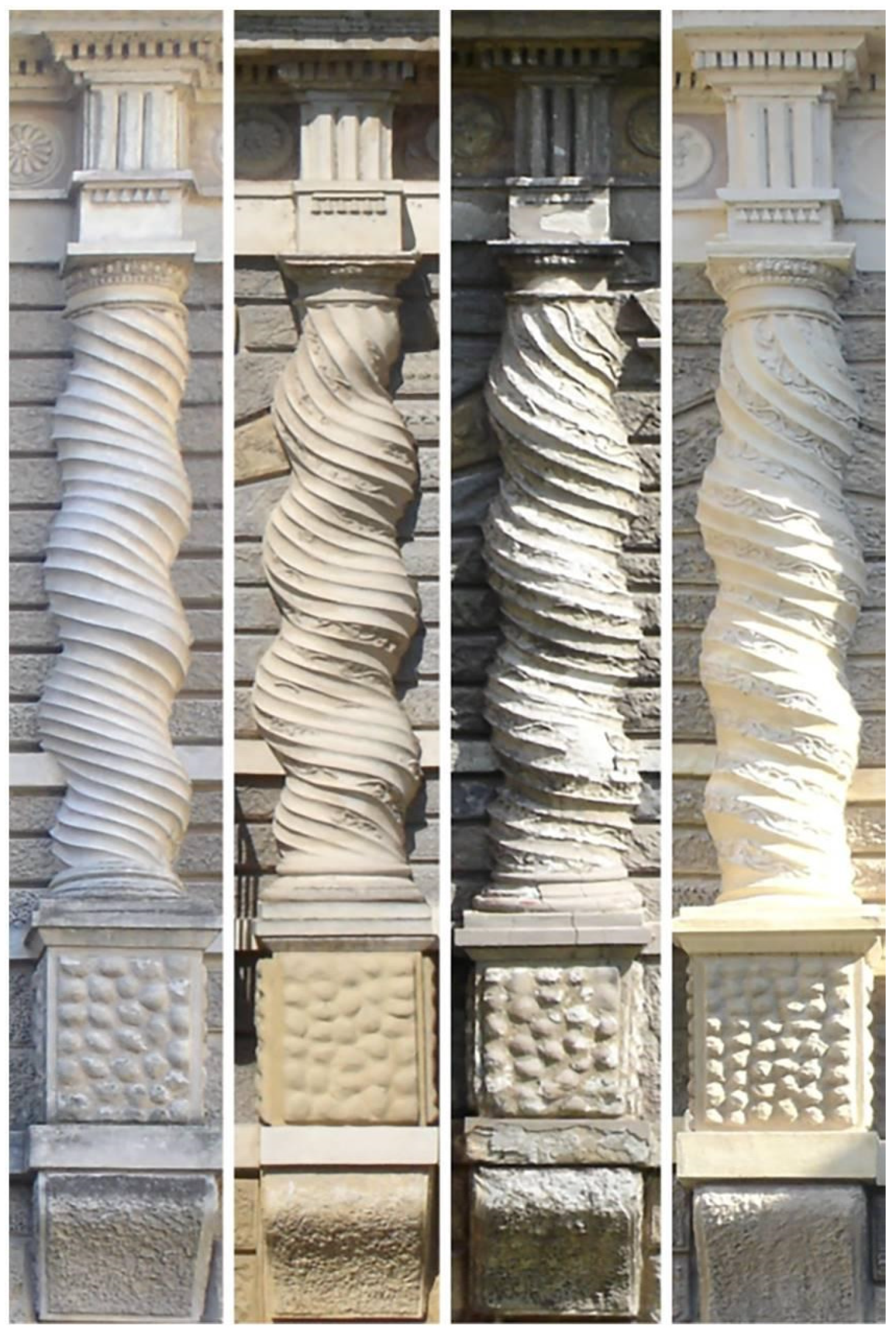
There are numerous elements of differentiation between the columns:
  • the columns of the side of the Rustica appear thinner and have a more sinuous movement of the rings, while the shaft of the columns of the longer sides are thicker;
  • only the columns of the south elevation are entwined with vine shoots, while in the rest of the elevations vines, bunches of grapes and other types of leaves are mixed up;
  • some of the vine shoots run along the flutings, following a straight line (in some columns of the south elevation), while others follow a sinuous line (especially in the north and west elevations);
  • the columns in the west and north elevations present two branches that constantly intertwine, drawing oval shapes;
  • the vine leaves of the south elevation are more simplified; in other elevations, where various types of leaves appear (combined with bunches of grapes), the element acquires greater detail and volume;
  • in the east and west elevations, towards the north side, the intertwining of flowers and leaves consists of a main branch on which a finer floral branch is wrapped.
It should be emphasized that the possible non-presence of stucco decoration does not mean that it had not been there previously. The columns have been the subject of restorations in which it was preferred not to proceed with the integration of the gaps in the floral decoration, by choosing to close them with smooth plaster.
The architectural element is realized in bricks, shaped and covered with several layers of mortar and a final stucco coating on which the floral decoration is applied, adjusted and remodelled in situ.
The internal brick body of the columns is made of bricks subsequently covered with layers of a mixture of lime and aggregates to build the body of the column. A subsequent layer completed the curvature profile. From the executed stratigraphies, it emerges that the final layer is a fine stucco with colour residues now preserved in small traces.
In the east elevation, a further layer of colour applied on this last one is present: a sort of rosy plastering consisting of three other layers: a white-pinkish outer layer, a white layer and a grey inner layer.
A trace of red pigmentation has been observed in a column of this front. In the east elevation, a red-earth and/or red ochre laying has been identified. The discovery could confirm the existence of an ochre polychromy on the surface of the columns of the elevation realized by Bertani.
The string-course frames are made by laying a double course of bricks placed in the shiner orientation and covered with a smooth, almost polished lime-based plaster. The glossy finish also characterizes the lintel above the windows made of bricks.
The shelves of the columns are made of layers of bricks arranged to create the curved S-shape ending with an upper horizontal plane. From the investigations conducted during restoration works, the presence of iron structural elements to support the overhang did not emerge. Probably, the masonry is made exclusively of protruding bricks covered with fractured plaster to create a rough surface.
The upper entablature repeats the classical scheme of metopes and triglyphs and constitutes a further useful element to give a sense of unity to the courtyard. However, comparing the sequence of triglyphs, pyramids, dentils and bas-reliefs (made both with moulds and freehand), we notice a rich variety of design and workmanship.
The elevated position contributed to a better preservation of the finish so that traces of colour were seen on all sides.
The execution technique of the entablature is observable from some gaps in the mortar. The brickwork is covered by a fine polychrome stucco with which both the decorative elements (triglyphs) and the scenes inside the metopes are modelled. The dentils were made with the same technique: a rowlock brick is covered with two layers of mortar and one layer of stucco.
Other elements, such as the ovoli decoration frame, were instead made by means of a mould, as can be seen from the mark left between the elements.
In the bas-reliefs inside the metopes, the moulding technique is combined with freehand execution, based on a charcoal reference drawing. In many scenes there are visible iron nail heads, used to ensure the anchoring of the projected portion of the masonry. Other metallic elements were inserted into the metopes to anchor objects or fabric on festive days.
In the metopes of the south and east façade, the workers realizing the decorations used a shared reference drawing, which served as a guide for the application of the stucco.
For the realization of the bas-reliefs, two types of mixture were used, a lime-based mortar with a coarser grain size and a fine-grained, white stucco.
The first type of mixture was used only in bas-reliefs (made by applying layers of material with the help of a special tool).
Instead, the stucco was used in bas-reliefs, executed both freehand and with the moulding technique, then later applied to the background of the metope.
The whole entablature presents a combination of yellow, red and purple that correspond to various interventions, carried out over small portions or large areas.
To better understand the colorimetric aspect of the frame, the investigations carried out by the ICR were useful. The results of the XRF analyses, carried out uniformly on the Cavallerizza fronts, revealed the presence of chromium traces (probably chromium yellow) and of zinc and titanium (probably white). This confirm the hypothesis that there was a yellow layer over the whole entablature.
Under these levels, in the background of the metopes, different stratigraphies are present depending on which of the spans they are on.
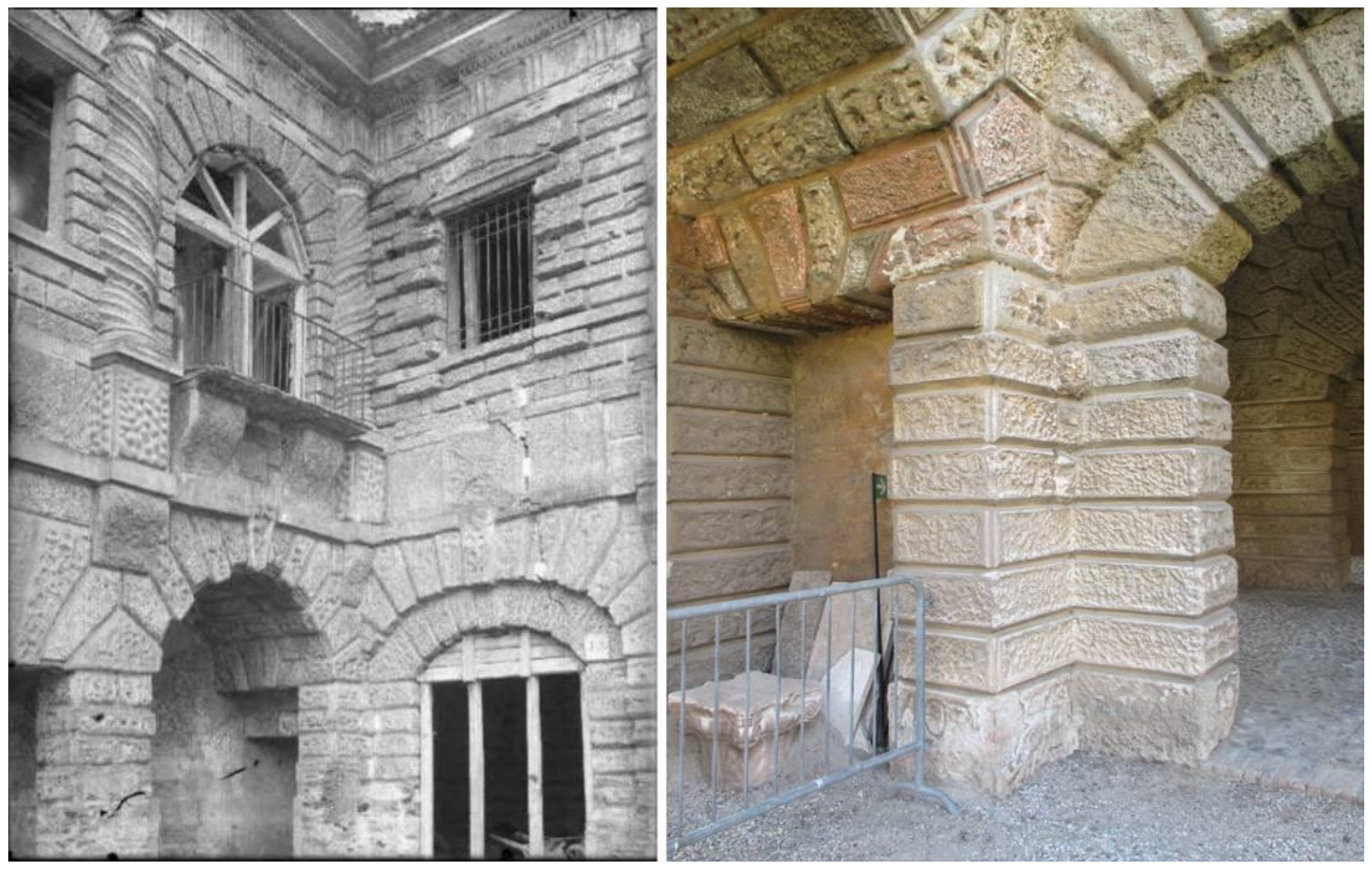
Observation and study of corner solutions help us to understand the architectural structure (Figure 12). The portion facing the lake was placed over the body of the Rustica, previously built by Giulio Romano. The junction between the inner wall of the Corridore and the Rustica shows a single half-column. The pilaster that completed the facade of the Rustica was hidden by this front (it can just be seen from the main floor of the loggia).
In the lower register, the pillar of the first arch on the lake side, inevitably, is embedded into the opening of the Rustica arcade. This inconsistency was corrected by inserting a further inner arch into this first span on the left. The expedient determines the creation of an angular pillar that, if it does not completely conceal the anomaly, at least attenuates its evidence.
In the opposite corner, at the junction between the Rustica and the Galleria della Mostra, the pre-existing old masonry does not hinder the presence of a rustic pillar supporting the last walled-up arch of the arcade. Above, a half-column is aligned with the underlying pillar. The Gallery intersects the Rustica laterally with respect to the spiral half-column.
On the upper floor, the semi-column resting on the Galleria side approaches (because of its projection) the corresponding Rustica column, creating coupled corner columns.
In the other corners of the Courtyard the appearance is much more regular. In fact, the enlargement of the original Loggia in the Galleria dei Marmi was designed to avoid the lack of symmetry so obvious on the opposite side.

3.2. State of Conservation

The state of conservation of the surfaces was defined through a direct reading of the building and a diagnostic project. The investigations were carried out by means of X-ray fluorescence analysis (XRF), Fourier Transform Infrared Spectrophotometry (FTIR), X-ray Diffraction (XRD) and Aqua-boy analysis. From the verification carried out, the state of conservation of the work is not sufficient.
The surfaces present serious degradation that manifests itself in various forms: cracking, de-cohesion, erosion, exfoliation, loss of material, stains and coherent and incoherent deposits. The mortars used to supplement previous interventions are no longer cohesive. The metallic elements necessary for anchoring fragmented surfaces are now compromised.
The degradation phenomena are widespread in the south and east elevations, more specifically on the lower parts of the rusticated ashlar, on the columns towards the corners and on the frame above the frieze. The mortars of the ashlar masonry and of the inner layers of the columns present a more serious state of degradation. This is due to the composition and mineralogical genesis of the mortars and to the restoration interventions that have made use of cement mortars.
In general, large deposits of pigeon guano, honeycombs and spider webs located in the undercuts of the entablature are evident. Copious and tenacious atmospheric particulate deposits are abundant in the east elevation and in the corners of the remaining elevations. On every carved surface, the atmospheric particulate has formed a grey deposit that prevents their correct interpretation. The distribution and build-up of particulate matter in the courtyard varies in relation to the orientation of the elevation, but also by the type of exposure.
The massive presence of calcium sulphate on the surfaces of the courtyard indicates that the degradation processes are to be linked mainly to the sulfation of the material. The loss of the mechanical properties of the mortars results.
The presence of humidity and rain, acting both as solvents and as a vehicle for pollutants, worsens the problem. The analyses carried out on the mortars of the ashlar showed high humidity in the first superficial layers. These are materials that tend to favour the internal accumulation of water, which then tends to evaporate, triggering a series of highly stressful processes. This has led to a variation in the chemical‒physical characteristics of the mortars now subject to disintegration phenomena.

4. The Project

Before dealing with the theme of the conservation project, it is necessary to consider the overall objective of the programme proposed by the person responsible for the conservation of the Palazzo Ducale. The information collected had to be filed and organized in order to be immediately available in case of need. This type of request has led to the preparation of a HBIM model (which will be discussed in the next section) characterized by various levels of detail. In other words, based on the type of information, three types of models (general, architectural and detailed) have been processed.
For general data concerning modern or historical cartographies, the general bibliography refers to a simplified model with geometric definitions. The data derived from the archival documents, in particular the restorations, have been linked to a model that incorporates the detail of the technological elements.
The project presented here was first reported in an Autocad representation (it should be remembered that the work in HBIM is still in the experimental phase and, to comply with the regulations in force, a project with traditional representations was also carried out), then revised in HBIM mode. This double representation allowed us to grasp the actual potential of the HBIM model, especially in the organizational aspects, for future management of preventive and programmed conservation.
In light of the different characteristics of the elevations (as highlighted above), we have tried to organize the project work, giving value to the differences found (Figure 13).
Based on the results of the investigations illustrated, interventions described both in tables and in specific sheets with all the operational phases were identified.
The overall objective of the operations is to guarantee the conservation of the original materials, when identified, and of the additions, even those of a relatively recent age.
The second objective clashes with the canonical conservative approach, which sees cement integrations as things that must be demolished and replaced. The study of the restoration interventions, starting from the early 1900s, clarified how the use of cement has been a common practice in different forms, such as mixed mortar or cement mortar. These changes in materials have mainly affected the lower portions, while the upper ones still preserve the ancient materials. Since numerous cement integrations are present (and are of good moulding technique, not approximate repairs), it has been decided to preserve them. Naturally, these choices make it necessary to relate them to the lime mortar elements and, above all, to limit their degradation by water.
Another criterion for evaluating the interventions is the typology of actions carried out in the recent past, of which we have evidence from project appraisals. Within these, it emerged that numerous resins and surface consolidatives have been used since the 1980s, implementing water damage.
Given the importance of the physical matter treated, the project used the materials as the guiding line for the interventions. Therefore, they are differentiated according to the type of material subjected to certain degradations. The identification of materials and degradation has, for now, been carried out directly. There may be additions to the definitions and to the type of problems during the construction site, when the choices will not only be conservative but also for the finishing.
The project for the surfaces has supported the choice of operating according to the different fronts, which guarantees a respectful attitude towards the different construction phases of the courtyard. This choice has made it necessary to introduce the use of numerous different types of plaster (rusticated or smooth) to which, in many cases, the intervention takes on a similar character while keeping a different material appearance.
The guiding criteria also foresee a dry cleaning phase: we want to avoid introducing water, even with nebulization, because the environmental humidity is already too dangerous to exacerbate it with prolonged watering, which would cause the salts to reactivate. The only actions to be carried out with water will involve sponges being soaked and then immediately squeezed out (so as not to cause drips) or the execution of compresses, at controlled levels of humidity. Dry cleaning will be carried out according to tradition and with ordinary equipment.
The cleaning operations aim at reducing the presence of salts and, in particular, of sulphates on the surfaces. Cement mortars, which appear de-cohesive and/or detached from the wall supports, will be removed, such as the synthetic polychromy applied during previous restorations.
We plan to integrate the gaps and to fill in the damage to the wall structure and to the external coating with mortar of good mechanical strength, permeability and breathability. The mortar, in addition to performing a protective action, must be formulated to have adequate texture and colour (to match the surrounding surfaces in an organic way). The integration must be carried out to be compatible with the original from a physical and chemical point of view. The mortar will be characterized by high porosity, which allows for the reduction of water accumulation by acting, at the same time, as a expendable material in case of continuous degradation. The colour must be chosen by functional and aesthetic criteria, similar to that of the material to be preserved. In case of the fragility of the binder that constitutes the rusticated plaster, it must be consolidated using inorganic materials, which can also be used for the possible adhesion of the polychrome layers to be preserved.

5. The H-BIM Model Setup

As described in previous sections, the operations conducted to study the fronts of the Cavallerizza courtyard were numerous and varied; they included archival research, geometrical qualitative survey, appraisals, on-site analysis and observations, which together led to choosing the best practices for the conservation project. Those actions are all part of a team effort that has never, in the history of the courtyard, been so comprehensive: loss or poor management of this content would be a major setback for all the professionals involved in its care.
A (relatively) new way to avoid this is Building Information Modelling practices: these drafting tools allow us to combine information and geometry in the same parametric modelling environment, which becomes a single container for all of the building’s data.
The Cavallerizza case is a valuable heritage building, hence the capital “h” before BIM. This branch of the subject is dedicated to drafting models that adhere as much as possible to the existing assets, a difficult task: parametric modelling uses standard, rigid tools not suited to the complexity and diversity of historic buildings.
The information then added to the virtual geometry of the building (an especially historically rich one) creates a proper database within the software, which can contain all information related to the past and, perhaps, the future care (in terms of programmes and actions) of the building.
In this case, an experiment with this technology has been carried out on a sample of the southern façade. One of the spans of the Rustica front was set up in a possible BIM layout. This is a simplified version of the geometry, given the fact that overall functioning had more importance than geometrical precision. However, it was drafted according to the laser scanner point cloud (product of the survey campaign) and therefore metrically correct, although simplified. The application used for modelling was Autodesk Revit, and the cloud was imported thanks to Autodesk Recap.
The main challenge, for the front of the Cavallerizza, is the varied superficial decorations that give the site its unique image. As described in the materials section (Figure 13 on the top), each element is different and has different conservation needs, so for each of them it is necessary to link different information.
This feature immediately highlights some problems specifically related to HBIM and Cultural Heritage [10]. On the one hand is the need to not lose the metric accuracy that can be achieved in the survey phase: modern BIM authoring software still does not allow one to manage all the irregularities of the built heritage and therefore forces important choices related to the accuracy of the final model (Adami).
The BIM modelling environments also dialogue with a finite number of technological elements; these often do not include historical elements and many types of decoration. In this case, tricks must be found to adapt the software tools (designed for new constructions)—the families in the case of Autodesk Revit—to the existing heritage.
The major problem is the ashlars. Typologies and shapes vary throughout the fronts and the levels and materials vary relative to the different interventions.
The average span contains more than 60 ashlars; managing them separately would create a huge number of free-standing elements in the same environment. Therefore, the decision was made to first create a curtain wall item for the whole rusticated portion of the main floor of the building. The quality of this element in the software is to have a container of panelling systems constituting a curtain wall. If in place of a panel, the mortar ashlar becomes the recurring element, so can describe this decoration effectively (the depth and shape of the ashlars can still be assigned singly).
This works smoothly on the portion of the main floor; less so on the ground floor, where the ashlars are much more irregular. In this case, the decision was made to accept this difficulty in modelling, with precision, all the elements of the architecture: this allows us, instead, to obtain an efficient representation of the other intended uses of the HBIM. Indeed, the strength of this system, and the core of the experiment, is linking different sources to one item, which was carried on despite difficulties.
The example shown in Figure 14 illustrates the three-dimensional object, the scheme for the different elements positioned on the surface of the main floor (approximately the material classification analysis) and the string-course frame. One of the quadrangular panels shows the power of this tool: information on the material and the damage (from two different sources) appear together in the description of the element.
The possibility of linking analyses and observations of various types (texts, photographs and drawings) to the elements of the BIM model, as shown in the example, is an important advance in the management of a restoration site: for the survey and analysis phase initially, but also later in the design and management of the architecture. Although it is not yet possible to fully exploit the potential of the BIM systems in the context of interventions in the existing heritage, this first step allows us to build new relationships: between the analysis and the object and between different types of analysis. This also leads to a greater integration of the team of researchers and professionals who intervene, each in its own field of expertise, in the restoration process, but who are often unable to make a comparison with each other.
Finally, the structure of the HBIM system is also suitable for monitoring the restoration site, allowing the precise recording of all the operations carried out and the attribution of the interventions to the various operators: it therefore becomes a sort of digital “site register”, which, however, is not a separate document, but is directly integrated with all the other data present in the system.

6. Conclusions

The article summarizes the project path activated for the conservation intervention at the courtyard of the Cavallerizza in Palazzo Ducale in Mantua.
As it emerges from the writing, the close collaboration between the Palazzo Ducale and the research institutions (Politecnico di Mantova and Centro Conservazione e Restauro Venaria Reale) has led to good results in every preparatory phase of the project.
Each body has addressed the problems expressed about the historical artefact, proposing and comparing possible conservative solutions as represented in the final plan, which is now in the contract phase. Contrary to what can be assumed, the Courtyard of Cavallerizza has undergone sporadic interventions in recent years and the memory of these operations has been lost.
Only a few archival documents testify to the operations carried out, and mostly without graphic localization. The lack of physical confirmation of the operations carried out in the past has made it necessary to carry out an investigation into the constituent materials of the decorative apparatus and the restorative materials. These investigations were also specifically aimed at identifying the technological and material differences made by Giulio Romano compared to the other architects who had worked on the construction.
The large amount of data has stimulated the development of a HBIM model, both to collect information from documentary research from the new surveys and to set up a programme for the management of projects.

Author Contributions

B.S. had responsibility for the historic research; A.A., L.F., O.R. for the survey; B.S. for the analysis of materials and state of conservation; B.S., A.M., D.L. for the project; A.A., B.S., O.R. for the BIM application.

Funding

This research was developed in the field connected to BIM (paragraph 5) within the project “Building Information Modelling for the planned conservation of Cultural Heritage: even a Geomatic question” (identification code RBSI144B5K) funded by the Ministero dell”Istruzione, dell”Università e della Ricerca in the national research framework SIR (Scientific Independence of young Researchers), 2014.

Acknowledgments

This project was made possible thanks to the collaboration of the Centro Conservazione e Restauro “La Venaria Reale” and especially the director of the Scientific laboratories Lorenzo Appolonia. A special thanks to PhD arch. Nazarena Bruno for the development of the database connected to the BIM application, which started as part of her PhD thesis.

Conflicts of Interest

The authors declare no conflict of interest.

References

  1. Berzaghi, R. Il Palazzo Ducale di Mantova; Electa: Milano, Italy, 1992; p. 7. [Google Scholar]
  2. L’Occaso, S. Il Palazzo Ducale di Mantova; Electa: Milano, Italy, 2002; pp. 14–15. [Google Scholar]
  3. Cassini, M.; Valli, L. Rilievi, indagini e ipotesi per l’analisi delle vicende costruttive dei cantieri di Giulio Romano nel Palazzo Ducale di Mantova. Master’s Thesis, Politecnico di Milano, Milano, Italy, 2010. [Google Scholar]
  4. Carpeggiani, P. L’ architettura dal Bertani al Viani. In Il Palazzo Ducale di Mantova; Algeri, G., Ed.; Electa: Milano, Italy, 2003; p. 192. [Google Scholar]
  5. Carpeggiani, P. Bernardino Facciotto: Progetti Cinquecenteschi per Mantova e il Palazzo Ducale; Guerini e Associati: Milano, Italy, 2005. [Google Scholar]
  6. Berzaghi, R. Il Palazzo Ducale di Mantova; Electa: Milano, Italy, 1992; p. 20. [Google Scholar]
  7. Algeri, A. Il Palazzo Ducale di Mantova; Electa: Milano, Italy, 2003; p. 116. [Google Scholar]
  8. Cottafavi, C. Ricerche e Documenti Sulla Costruzione del Palazzo Ducale di Mantova dal Secolo XIII al Secolo XIX; Reale Accademia Virgiliana: Mantova, Italy, 1939; pp. 171–182. [Google Scholar]
  9. Bertolotti, A. Le Arti Minori Alla Corte di Mantova Nei Secoli XV, XVI e XVII Ricerche Storiche Negli Archivi Mantovani Per A. Bertolotti; Archivio Storico Lombardo: Milano, Italy, 1888; p. 992. [Google Scholar]
  10. Adami, A.; Scala, B.; Spezzoni, A. Modelling and accuracy in a BIM environment for planned conservation: The Apartment of Troia of Giulio Romano. Int. Arch. Photogramm. Remote Sens. Spat. Inf. Sci. 2017, XLII-2/W3, 17–23. [Google Scholar] [CrossRef]
Figure 1. Aerial view of the Cavallizza Courtyard.
Heritage 02 00091 g001
Figure 2. Orthophoto of Rustica (elaboration of He.Su.Tech.).
Heritage 02 00091 g002
Figure 3. Orthophoto of the Galleria dei Marmi (elaboration of He.Su.Tech.).
Heritage 02 00091 g003
Figure 4. Orthophoto of La Galleria della Mostra (elaboration of He.Su.Tech.).
Heritage 02 00091 g004
Figure 5. View of the lakeshore Loggia.
Heritage 02 00091 g005
Figure 6. Digital photocomposition to describe the different stages of the geometric survey, from the point cloud (in greyscale on the left), to the orthophoto (centre) to the vector drawing (on the right).
Heritage 02 00091 g006
Figure 7. The lakeshore loggia described by different survey outcomes: two transversal sections (S1 and S2), the orthophoto of the façade (centre) and the opposite map of the ground floor (centre bottom) and first floor ceiling (centre top).
Heritage 02 00091 g007
Figure 8. The final outcome of the Rustica at the scale of 1:50: the elaboration is the overlapping of the Orthophoto and the vector draft.
Heritage 02 00091 g008
Figure 9. Detail photo with evidence of the bocciarda technique.
Heritage 02 00091 g009
Figure 10. Detail with different ashlars.
Heritage 02 00091 g010
Figure 11. A comparison of the different columns of the courtyard.
Heritage 02 00091 g011
Figure 12. Corner solution of the upper part (image on left: 1989) and of the lower part (today).
Heritage 02 00091 g012
Figure 13. Thematic analysis of the project (on the top, a material survey; on the bottom, a degradation survey.
Heritage 02 00091 g013
Figure 14. Example of a general section of the Cavallerizza façade with the scheme for the different elements positioned on the surface of the main floor (approximately the material classification analysis) and of the string-course frame.
Heritage 02 00091 g014

