Article

Electrochemical Evaluation of the Effect of Different NaCl Concentrations on Low Alloy- and Stainless Steels under Corrosion and Erosion-Corrosion Conditions

by
Frazer Brownlie
1,2,*,
Trevor Hodgkiess
3,
Alastair Pearson
4 and
Alexander Galloway
1
1
Department of Mechanical & Aerospace Engineering, University of Strathclyde, Glasgow G1 1XJ, UK
2
Weir Advanced Research Centre, Glasgow G1 1RD, UK
3
School of Engineering, University of Glasgow, Glasgow G12 8QQ, UK
4
Ascott Metallurgical Ltd., Glasgow KA3 1RL, UK
*
Author to whom correspondence should be addressed.
Corros. Mater. Degrad. 2022, 3(1), 101-126; https://0-doi-org.brum.beds.ac.uk/10.3390/cmd3010006
Submission received: 17 December 2021 / Revised: 4 February 2022 / Accepted: 17 February 2022 / Published: 19 February 2022

Abstract

:
The main objective of this study was to assess the influence of salt concentration on the corrosion behaviour, including the role of hydrodynamic conditions, of two broad classes of ferrous engineering materials. These are comprised of alloys, typified by a low-alloy steel (UNS G43400) that corrodes actively in aqueous conditions and a range of passive-film-forming stainless steels (UNS S31600, UNS S15500 and UNS S32760). Corrosion monitoring employed electrochemical (potentiodynamic polarisation) techniques. Three concentrations of aerated sodium chloride were utilised: 0.05 wt% NaCl, 3.5 wt% NaCl and 10 wt% NaCl. In quiescent, liquid impingement and solid/liquid impingement conditions, the corrosion rate of the low-alloy steel was observed to peak at 3.5 wt% NaCl, followed by a reduction in 10 wt% NaCl solution. These findings expand the range of previously reported trends, focused on static conditions. Such corrosion rate/salinity trends were observed to be dictated by the progress of the anodic reaction rather than influence on the cathodic reaction. Detailed studies were undertaken using segmented specimens to facilitate comparisons of the influence of hydrodynamic variations on corrosion behavior; these revealed that such variations influence the corrosion rates of low-alloy steel to a much lesser extent than the effect of changes in salinity. For the stainless steels, in quiescent and flowing conditions, when surface passive films are stable, there was a constant increase in corrosion rate with salinity. In solid-liquid conditions, however, the periodic film-destruction/repassivation events resulted in a similar corrosion rate/salinity trend to that displayed by the low-alloy steel, but with a much larger effect of hydrodynamic conditions. Additonally, the study revealed an underlying influence of stainless steel composition that mirrored, to an extent, the corrosion behaviour in pitting/re-passivation situations

1. Introduction

Natural and process waters, which are used in many industries, can be of variable nature in terms of chemical constitution and physical characteristics. Clearly, the durability of engineering equipment, such as pipes, valves and pump components, is related to the water properties. One relevant feature of water is the total amount of dissolved salts (TDS)–often referred to as the salinity. This can vary between extremely low levels in many freshwaters, through concentrations of around 3% for ocean seawater. More saline conditions (5–10 wt% or more) are found in some local seas (Persian Gulf) and water after some industrial operations is even more saline (e.g., up to 30 wt% in the oil/gas [1] and mining sectors). The increasing scarcity of fresh water and the understandable concern of society for the global environment places ever more pressure on industrial users of water to employ and re-use water of higher salinity [2,3,4]. Global demand for freshwater is constantly increasing, which means that industrial applications, such as fluid transport equipment, will be required to operate in more saline environments. As an example, the Chilean Copper Commission [5] in 2018 predicted a 230 wt% increase in the use of seawater in the next decade–it is expected that all new and extended Chilean mines will need to use seawater or treated seawater.
It is clearly of interest to be able to assess the effect of the salinity of water on the durability of metallic materials–especially ferrous alloys that represent the major classes of fluid-handling constructional materials. In terms of general durability, there are two broad classes of steels:
  • plain carbon and low-alloy steels that possess inherently poor corrosion resistance in most aqueous conditions
  • stainless steels, which generally exhibit much superior durability.
In terms of corrosion behaviour, a number of studies on carbon steel and low-alloy steel in air-saturated saline solutions have been carried out over the years. Thus, Revie and Uhlig [6] and Cheng and Huang [7] report that the corrosion rate of iron and low-alloy steel, in aerated water at ambient temperature, reaches a maximum at about 3 wt% NaCl. Zeng et al. Further, [8] state (but without displaying the results) that the maximum corrosion rate of carbon steel lies at 1 wt% NaCl. These previous papers do, however, only provide very basic explanations of their observed trends. Although this paper is focused on aerated, non-acidic waters, investigations [8,9,10] of the role of salinity on the corrosion of iron and carbon steel in water saturated with carbon dioxide also have some relevance–despite the obviously different cathodic reactions that occur in such an environment. These studies also report a rather similar trend of increasing corrosion rate with salinity, followed by a subsequent decline in rates, but with an apparent maximum corrosion rate at 1 wt% NaCl or less.
The corrosion behavior of stainless steels in quiescent water is of course characterised by the high degree of protection afforded by the presence of a surface film of Cr-rich oxide. [11]. The stability of this protective film in saline waters, such as seawater, is substantially affected by the composition of the stainless steel–particularly the chromium, molybdenum and nitrogen contents [12,13]. Studies of the corrosion resistance of stainless steels have tended to concentrate on these alloy composition effects rather than detailed aspects of the water composition. As would be expected, however, waters with higher contents of chloride ions have been observed to increase the vulnerability to localised breakdown of the passive film [14,15].
As regards the additional influence of water turbulence, there appear to have been no systematic studies of the influence of water salinity on corrosion behaviour in high-velocity, single phase saline fluids. One early investigation by Uhlig and Morrill [16], conducted in slightly turbulent conditions and at a relatively high temperature of 90 °C, indicated that the maximum corrosion rates of mild steel and 18% Cr-8% Ni stainless steel were at 2 wt% NaCl and 4 wt% NaCl respectively.
In many circumstances, corrosive attack occurs in conjunction with surface damage involving various types of mechanically-induced wear. Examples are fretting, sliding and abrasion, and when such wear damage occurs in a corrosive environment, the resulting phenomenon is usually termed “tribo-corrosion.” When the wear component comprises surface damage caused by impacting particles suspended in a corrosive fluid, the deterioration process is usually referred to as “erosion corrosion” and can therefore be considered as a sub-set of tribo-corrosion. Some natural and industrial waters contain appreciable burdens of suspended solids, such as wet mineral processing operations [17], in which circumstances constructional materials are thereby vulnerable to erosion corrosion The mechanisms of such damage are usually found to consist of purely mechanical, purely corrosion, and often complex interactions between these two processes. The latter features, termed synergy or additive effects, have been the subject of investigations [18,19,20] throughout the years.
There have been numerous studies of erosion-corrosion in a single solution-usually 3.5 wt% NaCl to mimic seawater [21,22,23,24]. Research, which directly examines the effect of salinity on the erosion-corrosion of materials in a controlled manner, has tended to make use of only two salinities, namely 3.5 wt% NaCl and freshwater [25,26]. At salt concentrations exceeding 3.5 wt% NaCl, investigations on erosion-corrosion have been extremely limited. In many instances, the pure mechanical component comprises the most dominant contributor to overall material loss by erosion corrosion and, in such circumstances, sensitivity to water salinity might not be expected. Recent work [27] has demonstrated, however, that the role of corrosion-related damage during erosion corrosion is significant. Thus, low-alloy steel was observed to suffer substantially enhanced attack in a 3.5 wt% NaCl solution compared to damage in an aqueous solution of 0.05 wt% NaCl, but with no clear evidence of further increase in material loss when raising the salinity to 10 wt% NaCl. Moreover, the expected margin of superiority in the durability of stainless steels over low-alloy steel was significantly compromised during erosion corrosion at a salt concentration of 10 wt% NaCl. Further analysis [28] revealed complex influences of corrosive damage in the overall erosion corrosion deterioration process associated with varying water salinities.
It is apparent that there are large gaps in assessing the trends and the understanding of the effect of salinity on commonly used steels under corrosion and erosion-corrosion conditions. To address these uncertainties, this paper is devoted to the findings, and interpretation, of a detailed study focused on the corrosion behaviour of a number of steels in a range of salinities. The experimental work involved a low-alloy steel and three different grades of stainless steel exposed to a range of conditions. These comprised quiescent water, liquid impingement (solids free) and impingement of saline solutions that contain suspended sand particles. The emphasis was on monitoring the electrochemical response of the various materials. Different types of specimen geometry were employed in order to gain a closer appreciation of the role of hydrodynamic conditions on corrosion behavior.

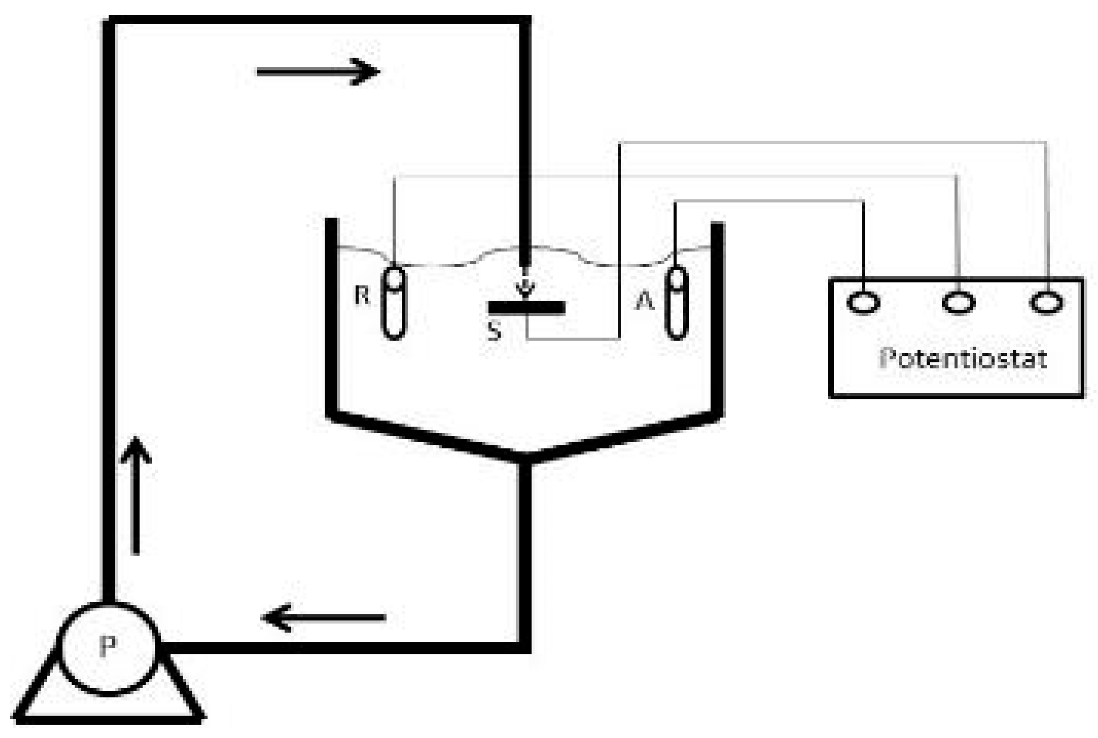
2. Materials and Methods

The four alloys considered in this study comprised a high-strength low-alloy steel (UNS G43400), a precipitation-hardened martensitic stainless steel (UNS S15500), an austenitic stainless steel (UNS S31600) and a superduplex stainless steel (UNS S32760). The nominal chemical compositions of each steel are presented in Table 1, and the measured hardnesses of each steel are displayed in Table 2.
Three test conditions were involved in the programme:
  • In quiescent saline solution
  • In “liquid impingement” (“LEC”) conditions, namely solution impinging on the specimen, but without carrying any suspended sand particles
  • In “solid-liquid” impingement (“SLEC”) conditions, involving an impinging solution containing a burden of suspended sand particles.
The solid-liquid impingement experiments were carried out in free erosion-corrosion (FEC) conditions with a recirculating, submerged-impingement, slurry-jet test rig (Figure 1) that has been described in detail in earlier publications [29,30]. The duration of the tests was 1 h. The fluid impinged at an angle of 90° upon the specimen surface through a nozzle of 4 mm diameter at 18 m/s with a temperature of 40 ± 1 °C. The nozzle was offset from the specimen surface by 5 mm. Three slurries were employed to observe the effect of salinity and they consisted spherical silica sand particles of size around of 500 μm (Figure 2) suspended in 0.05 wt% NaCl, 3.5 wt% NaCl or 10 wt% NaCl aerated, aqueous solution. The sand concentration was measured (by collecting samples at the nozzle exit) to be 0.5 g/L. The specimens (38 mm diameter and 17 mm thick) were ground to 1200 grit paper prior to testing. The test protocol employed for the liquid impingement experiments was identical to the above-described approach, but utilised an impinging stream that contained no added sand particles.
In-situ potentiodynamic polarisation scans–as used in previous studies [22,23] -were carried out to assess the electrochemical corrosion rates of the materials in all three test conditions. This approach involves the gathering of data that facilitates appropriate determination of deterioration mechanisms in the different hydrodynamic conditions The corrosion monitoring exercises, undertaken in static solution, were also evaluated in the jet impingement rig, but in quiescent conditions.
The polarisation tests were conducted 15 min after the sample was submerged to allow for the free electrode potential, Ecorr, to stabilise. A Gill AC potentiostat was utilised for the potentiodynamic scans. Platinum was used for the auxiliary electrode and Ag/AgCl/saturated KCl was employed as the reference electrode. The tests were conducted by shifting the initial electrode potential either 20 mV more positive (cathodic) or 20 mV more negative (anodic) than the free electrode potential, hence ensuring that the transition point (the free corrosion potential, Ecorr) would be captured. Scans then continued to 300 mV more negative (cathodic) or 300 mV more positive (anodic) at a sweep rate of 10 mV/min. The chosen ranges were sufficient to evaluate corrosion current density measurements, Icorr in mA/cm2, by way of Tafel extrapolation [31]. Icorr is an indirect (electrochemical) measure of corrosion rate that is related to the corrosion rate in engineering units (e.g., mass loss rate) via Faraday’s Laws.
To conduct the polarisation tests, an electrically conductive wire was connected to the rear of the specimens, which were then cold mounted in epoxy resin. This ensured that only the directly-exposed surface was corroding. Almost all research investigations of erosion corrosion utilise a single specimen with a surface area much larger than the region directly impacted by the fluid stream. Such a configuration does have the merit of simulating many industrial situations where a small area is subjected to a high-velocity stream, but is surrounded by a larger zone that experiences lower velocity and lower angle of impact. The additional use of segmented samples (Figure 3) facilitates important additional comparative information of the disparate rates and mechanisms of attack in the two regions [29]. The segmented samples were created by cutting a 0.5 cm diameter cylinder from the centre of the specimen onto which the jet would impinge (DIZ). The sides of this cylinder were insulated with a polymer to prevent electrical connection between the DIZ and the outer region (OA) and both regions were connected to an electrically conductive wire as with the full polarisation samples. The layout and dimensions of these segmented samples are shown in Figure 3.
A feature of submerged jet experiments, conducted on single specimens in which the area of the directly-impinged zone is less than the overall area, is that the findings essentially represent an “average” of corrosion rates experienced in distinctly different hydrodynamic regions and therefore mask any behavioural differences between these two distinct regions. The potential benefit of the procedures described above–involving electrochemical monitoring of segmented specimens–is to provide a means of differentiating any trends associated with the two zones [29].
Examples of polarisation plots, resulting from duplicate tests, are shown in Figure 4. These indicate the variability between duplicate tests. In order to simplify the presentation of the results, however, such duplicates plots are not presented in subsequent figures, but are tabulated as “measured values” of corrosion currents (Icorr) in the results tables (see for example, Table 3).

3. Results

3.1. Electrochemical Monitoring–Stainless Steels
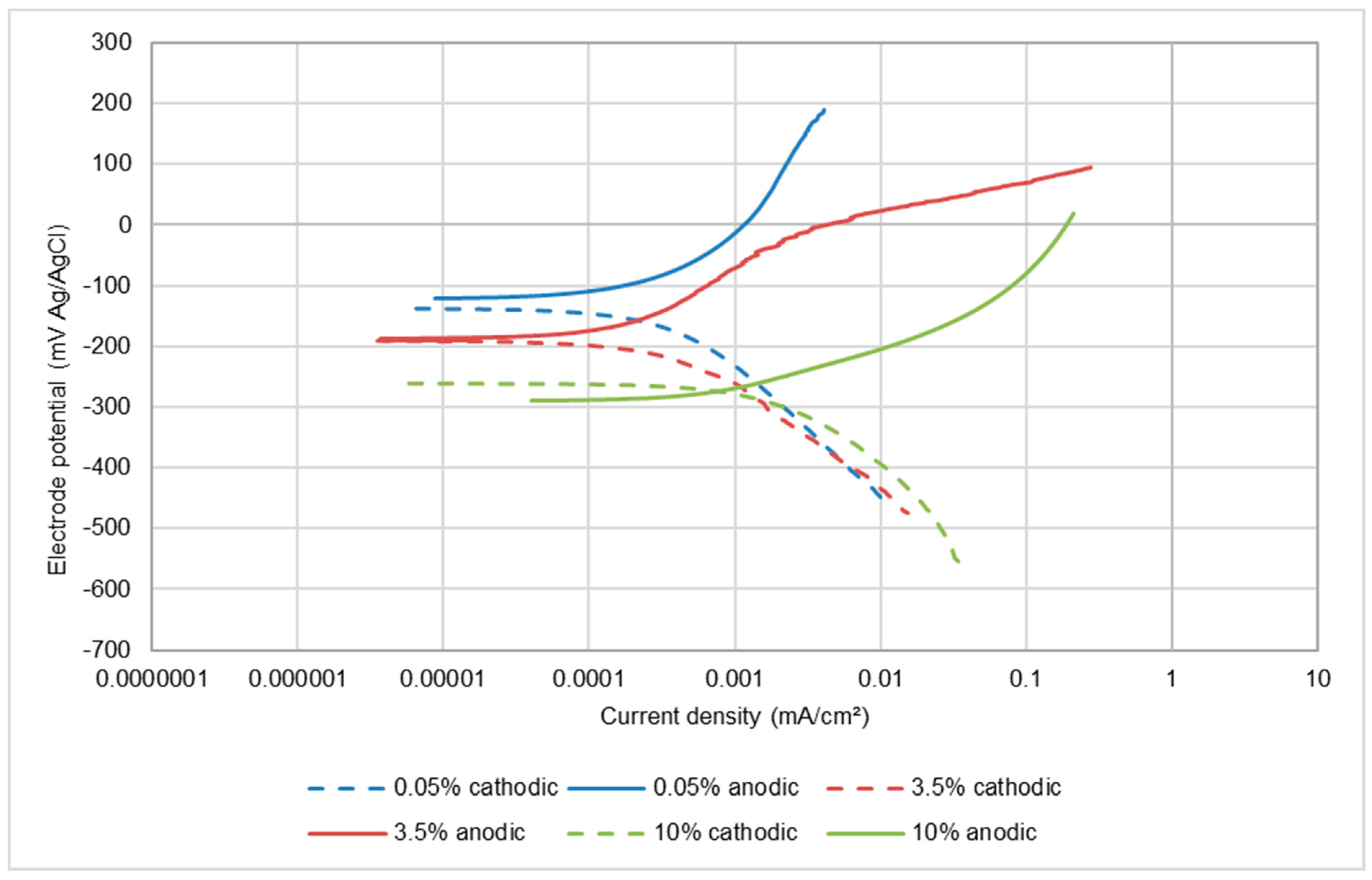
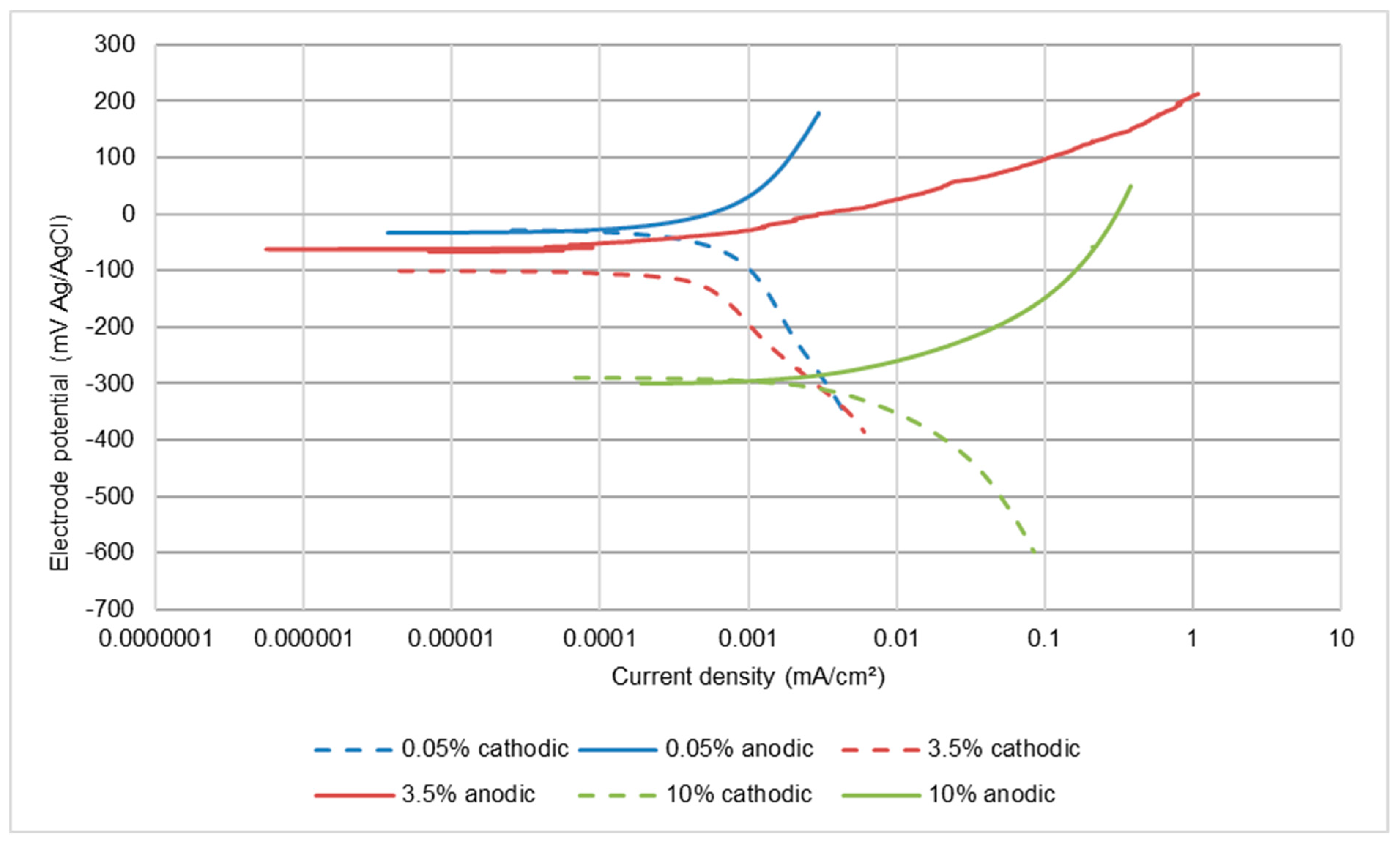
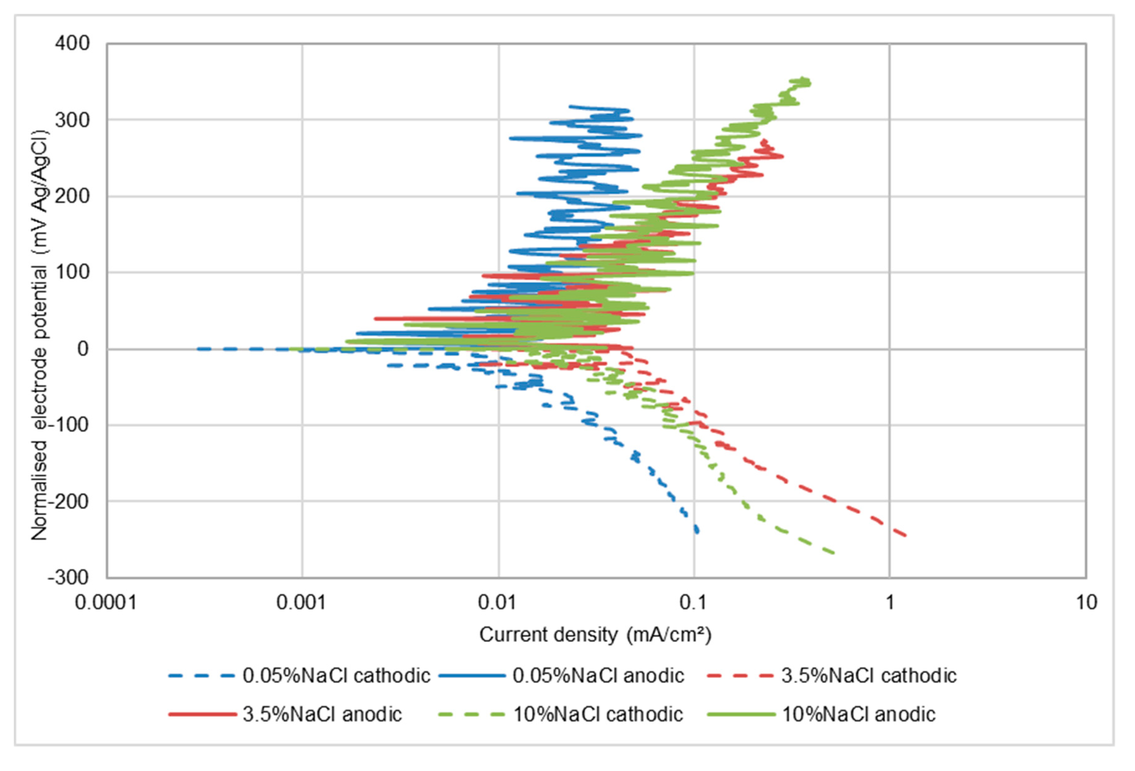
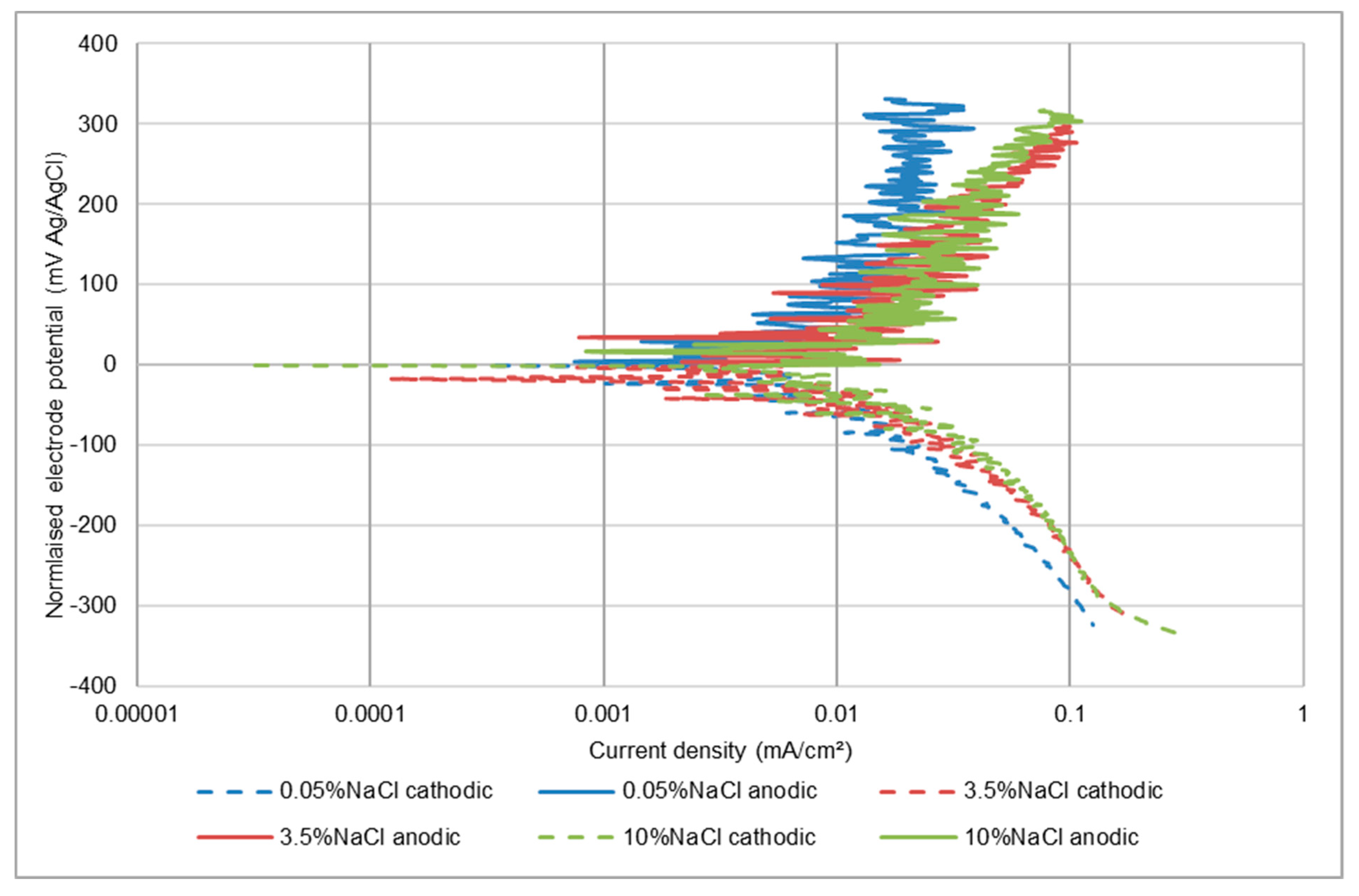
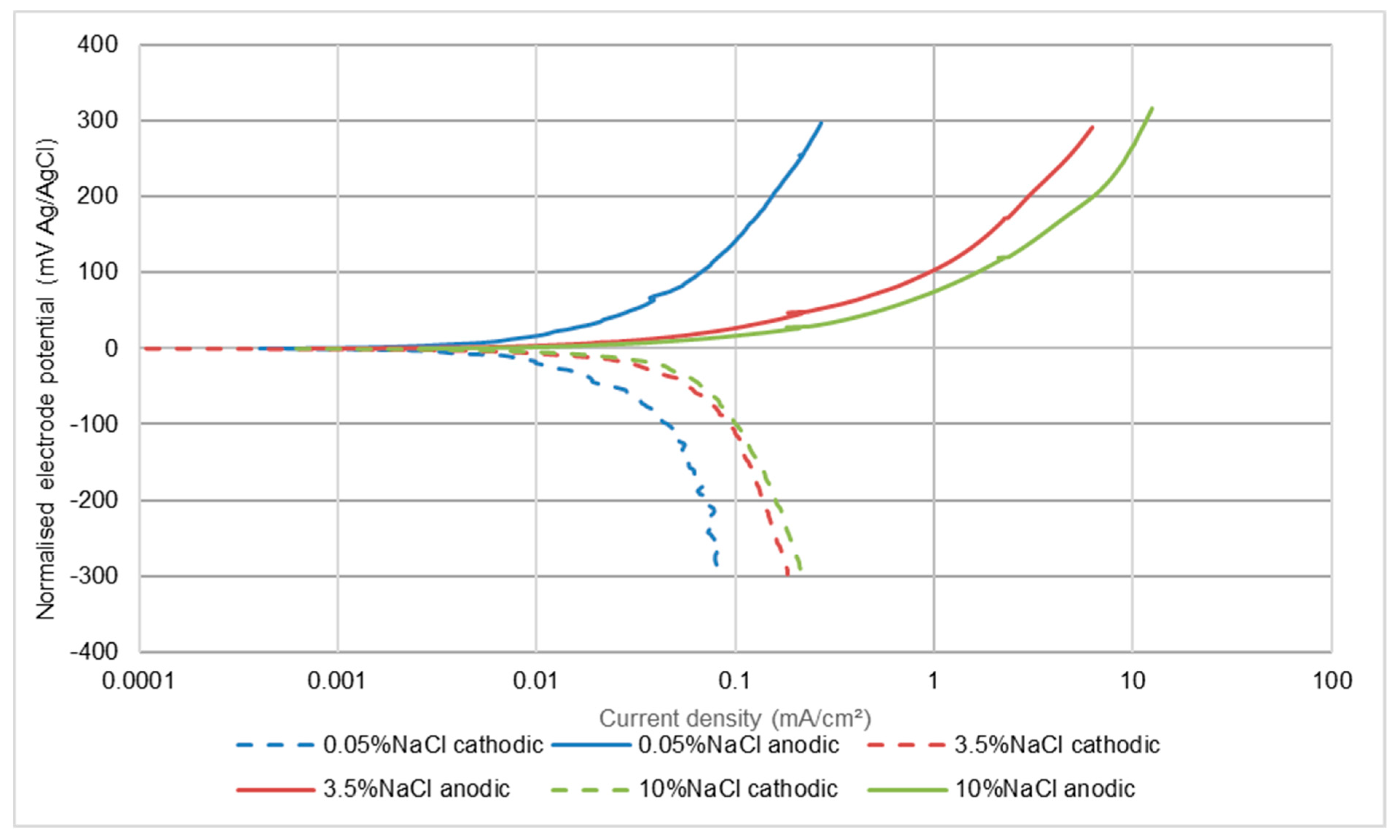
3.1.1. UNS S31600

The potentiodynamic polarisation scans, shown in Figure 5 and Figure 6 for UNS S31600 in static and LEC conditions, indicate that the corrosion process is anodically controlled with no evidence that an increase in salt content is causing any reduction in the rate of the cathodic reaction. Table 3 demonstrates that the corrosion rates increase with rising salinity and are higher in the LEC situation.
Figure 5. Polarisation plots for UNS S31600 in static conditions.
Cmd 03 00006 g005
Figure 6. Polarisation plots for UNS S31600 in liquid impingement (LEC).
Cmd 03 00006 g006
Table 3. Influence of salinity on corrosion rates of UNS S31600 steel in the different hydrodynamic conditions.
wt% NaClStatic (Quiescent)Liquid Impingement (LEC)
Ecorr (mV)Icorr (mA/cm2) MeasuredIcorr (mA/cm2)
Average
Ecorr (mV)Icorr (mA/cm2) MeasuredIcorr (mA/cm2) Average
0.05−1200.0002, 0.00030.00025−320.0005, 0.00070.0006
3.5−1870.0002, 0.00040.0003−660.0005, 0.00090.0007
10−2890.0017, 0.00180.0018−3750.004, 0.0060.005
wt% NaCl Solid-liquid impingement (SLEC)
Ecorr (mV)Icorr (mA/cm2)
measured
Icorr (mA/cm2)
average
Erosion-enhanced corrosion *
(mA/cm2)
Erosion-enhanced corrosion, % of Icorr SLEC
0.05−3690.005, 0.0150.0100.009797
3.5−3750.022, 0.0320.0270.026798
10−4310.008, 0.040.0240.02292
* The “erosion-enhanced corrosion” parameter represents one of the synergy components that contribute to the overall material loss in erosion corrosion. It has been calculated by subtracting the corrosion rate measured in static conditions from the corrosion rate obtained in SLEC conditions.
Exposure to an impinging solution containing solid particles (SLEC) brought about a substantial change in corrosion behaviour with the most evident feature (Figure 7) being the fluctuating current exhibited by the anodic polarisation plots. This and succeeding polarisation plots are presented in a “normalised form” by displaying the free corrosion potential as zero in order to facilitate comparisons in polarisation behaviour. The actual free-corrosion potential (Ecorr) values, however, are presented in Table 3 and succeeding results tables. The observed oscillating currents have been reported widely [24,29,30] and are attributed to alternating passive-film de-passivation/re-passivation behaviour promoted by the impingement of sand particles. This clearly contributes to an enhancement of the overall corrosion rate of the alloy-as shown in Table 3 which also demonstrates (for the two lowest salinities) considerable negative shifts in free corrosion potential in solid/liquid impingement compared to the other two test conditions. The influence of salinity has also apparently changed somewhat from that found in quiescent and LEC conditions in that there is a fairly substantial increase in corrosion rate from the lowest salt concentration to 3.5 wt% NaCl solution, but a detectable reduction in rate between 3.5 wt% NaCl and 10 wt% NaCl.
The “erosion-enhanced corrosion” parameter (Table 3) represents one of the synergy components that contribute to the overall material loss in erosion-corrosion. A formal definition of the term, “synergy” is given in ASTM G119, [32] which states, in relation to the erosion-enhanced corrosion component, that this parameter, ∆CE, is calculated by subtracting the corrosion rate in the absence of wear from the corrosion rate in erosion-corrosion conditions. Hence, ∆CE can be defined as synergy and can be calculated as follows:
Δ CE = I corr   ( SLEC )   I corr   ( s )
where Icorr (SLEC) is the corrosion current density in SLEC conditions and Icorr (S) is the corrosion current density measured during static immersion. In this study, the values of ∆CE obtained demonstrated very clearly that the corrosion rates in static conditions were very considerably increased under SLEC conditions. Table 3 yields corrosion rates being enhanced by factors of between 92–97% and, for all the other alloys, the ∆CE proportion (Table 4, Table 5 and Table 6) was often above 80% and always in excess of 50%.
As shown in Table 3, ∆CE represents a very substantial factor in the magnitude of corrosion in severe hydrodynamic conditions–as is also the case for the other two grades of stainless steel (Table 4 and Table 5).

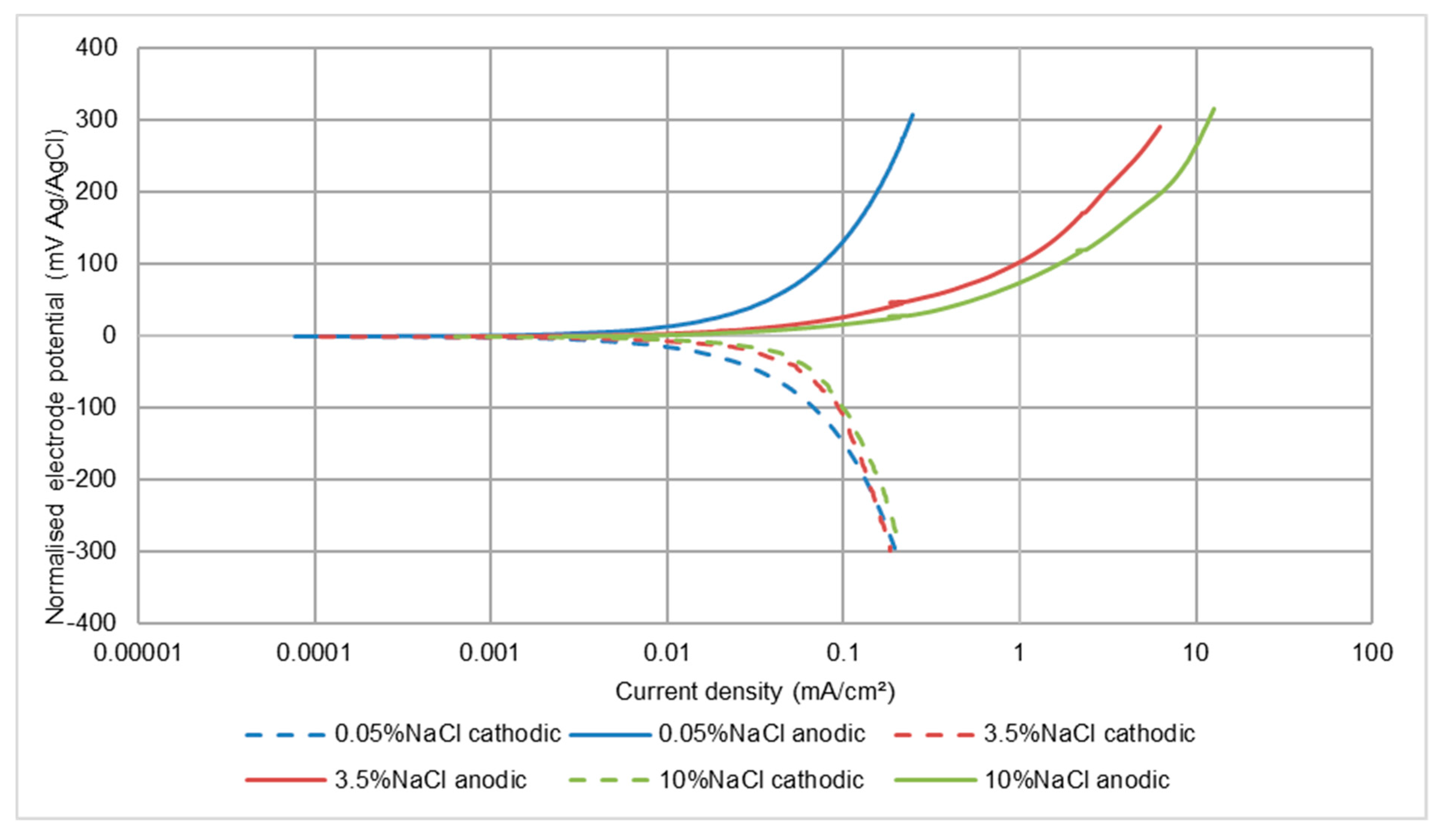
3.1.2. UNS S15500 Stainless Steel

The trends of corrosion rates with wt% NaCl for this alloy are summarised in Table 4. In line with the behaviour of the UNS S31600 steel, in static and LEC conditions the corrosion rate was found to increase with wt% NaCl. In SLEC conditions, there was again good correspondence between this alloy and the UNS S31600 stainless steel in displaying an increase in corrosion rate as the NaCl concentration was raised from 0.05 wt% to 3.5 wt% NaCl, but with a modest decrease in corrosion rate upon raising the salinity to 10 wt% NaCl.

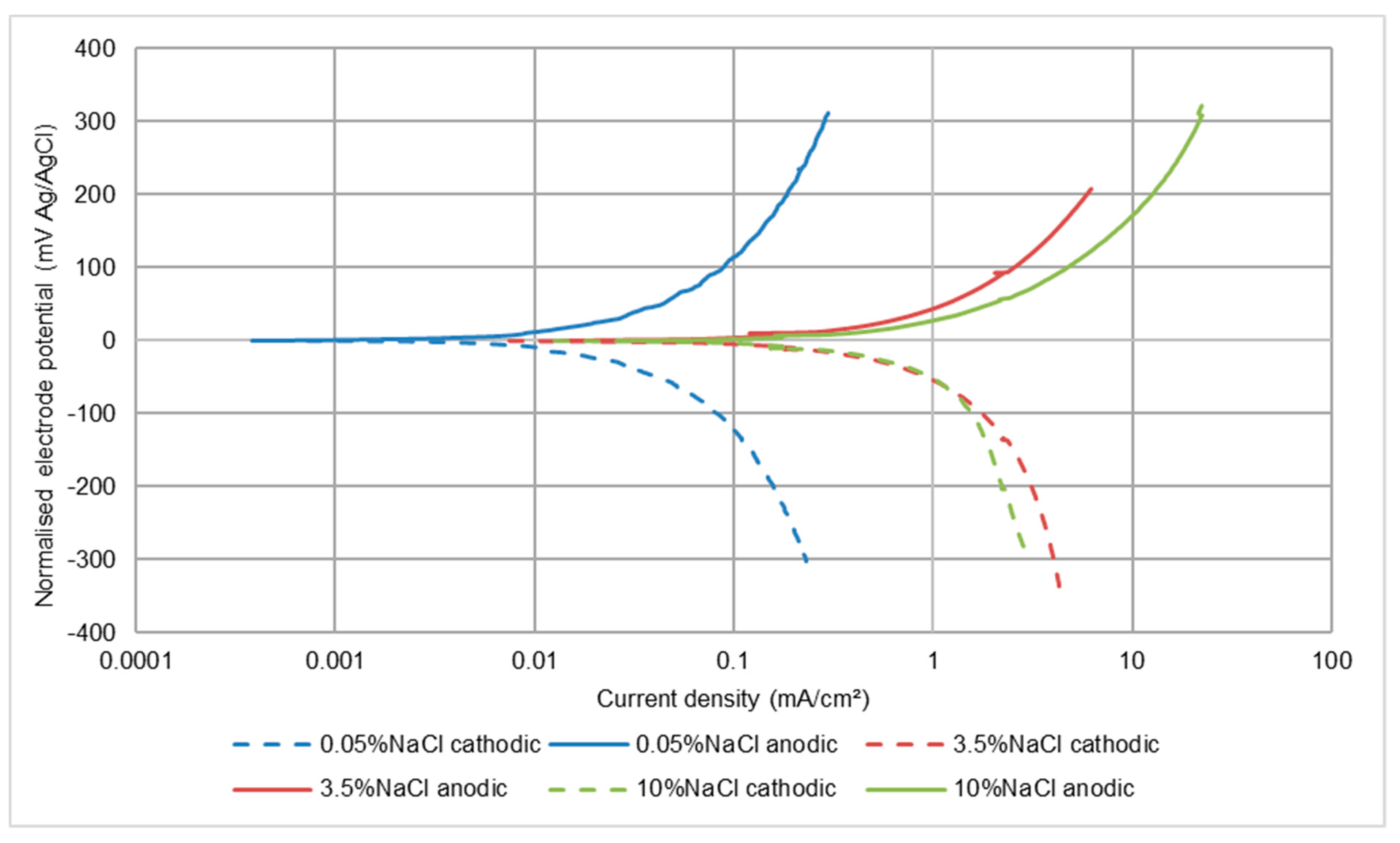
3.1.3. UNS S32760 Stainless Steel

In common with the other two stainless steels, in static conditions, this steel displayed (Table 5) a continuous increase in corrosion rate with salinity. In liquid impingement (LEC) conditions, however, a difference was that the UNS S32760 alloy exhibited a marginal decline in corrosion rate in the highest salinity solution. In SLEC conditions, an increase in corrosion rate was observed up to 3.5 wt% NaCl but no further increase upon rise in salinity to 10 wt% Nacl. As comparisons between Table 3, Table 4 and Table 5 and Figure 7 and Figure 8 reveals, the corrosion rate of the UNS S32760 grade in SLEC conditions was much lower than that of the other two stainless steels.

3.2. Electrochemical Monitoring–Low Alloy Steel (UNS G43400)

In all circumstances, the recorded corrosion rates for this low alloy steel were, not unexpectedly, much higher than for the stainless steels. The other main difference was that, in all three test conditions, the effect of salinity was to cause a large increase in corrosion rate between 0.05 wt% NaCl and 3.5 wt% NaCl, but no further increase when raising the NaCl concentration to 10 wt% NaCl. This feature is illustrated in Figure 9, Figure 10 and Figure 11 and also is summarised in Table 6. It appears that both half reactions are accelerated by an increase in NaCl concentration from 0.05 wt% NaCl to 3.5 wt% NaCl, but that the effect is greater on the anodic reaction. This aspect is also supported by the relative changes that were observed in the Ecorr versus wt% NaCl values.
In quiescent conditions, the corrosion rates were substantially less than in liquid impingement and the free corrosion potentials were more negative than in flowing conditions. Thus the main cause of this feature was depolarisation of the cathodic reaction, probably by increasing the rate of mass transfer of oxygen to the metal surface via a thinner diffusion boundary layer [33]. The effect of increasing the NaCl concentration was less dramatic, in that the acceleration in corrosion rate between the most dilute solution and the 3.5 wt% NaCl solution was significant, but not substantial and the measured rates in the 10 wt% NaCl liquid were the same as in 3.5 wt% NaCl. A useful aspect of examining the polarisation plots in static conditions (Figure 9) is that analysis of any trend, with respect to salt concentration changes, is unlikely to be complicated by changes brought about by the increased supply of fluid to the metal surface in flowing conditions. Such considerations indicate that there is no evidence of the cathodic reaction being suppressed in more-saline situations.
As might be expected, the corrosion rates were elevated in the solid-liquid slurry (SLEC), but the relative effect of raising the salt concentration followed the same trends in terms of increases in the rates of both electrode reactions, trends in corrosion current and Ecorr changes. Notice also, in relation to Figure 11, that the anodic polarisation graph did not exhibit current fluctuations. This is because this steel undergoes active corrosion; hence, there was no passive film to destroy. As for the stainless steels, the erosion-enhanced corrosion factor is substantial.
Figure 12 provides a good illustration of the relative performances of the suite of alloys with the relatively high corrosion rate exhibited by the low alloy steel compared to the stainless steels. The relative corrosion rates of the stainless steels reduce as their chromium and molybdenum concentrations (Table 1) increase. It is noticeable that, at the high rates of the cathodic reaction on the low alloy steel, there is evidence of concentration polarisation occurring to limit the reaction rate on account of restricted oxygen supply.

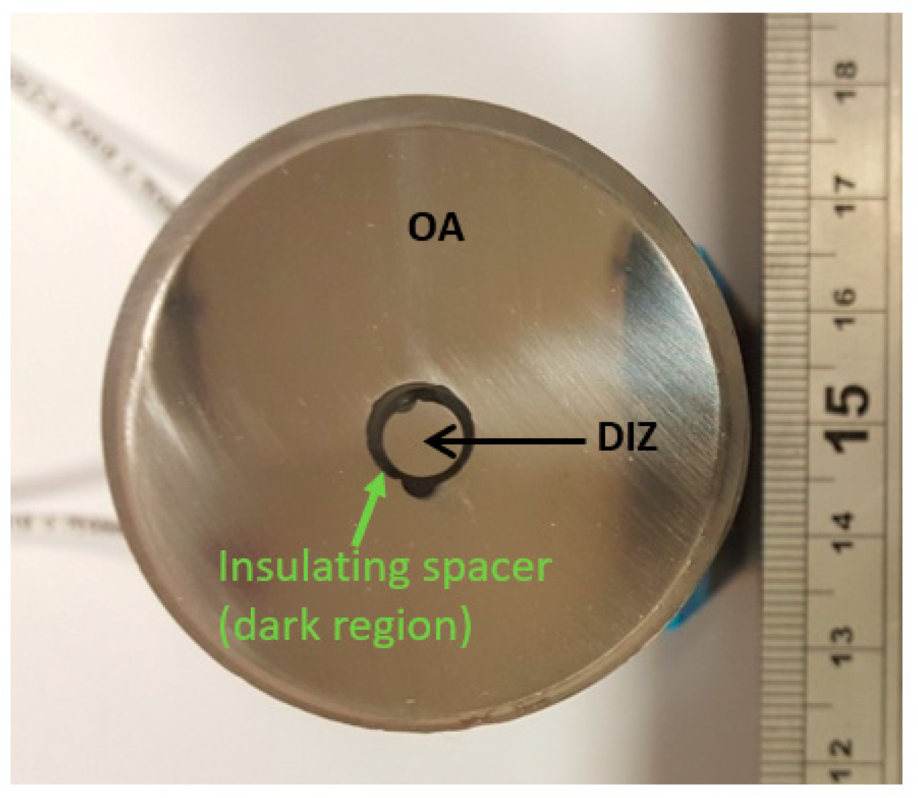
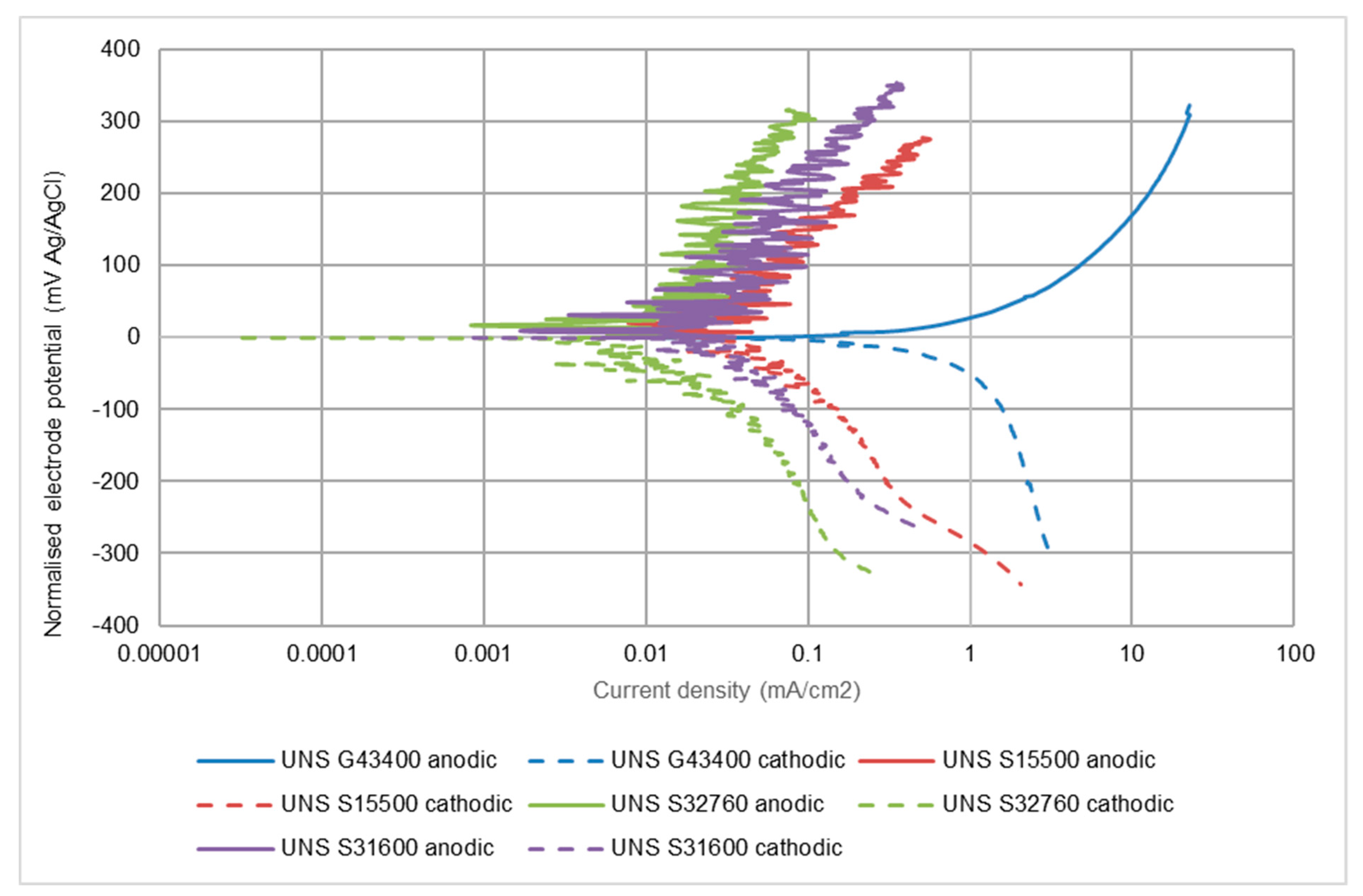
3.3. Electrochemical Monitoring–Segmented Samples

This part of the study focused on undertaking anodic polarisation scans on segmented specimens in the most-severe SLEC conditions in order to compare the behaviour under the two hydrodynamic extremes. These are the DIZ and the outer zone (OA) of a sample, subject to an impinging stream that is directed onto just part of the surface of a component. This approach facilitates the interrogation of corrosion behaviour in the two extremes of high impinging velocity at approximately 90° and at almost grazing incidence and lower velocity outwith the directly impinged region [22,29,30,34].

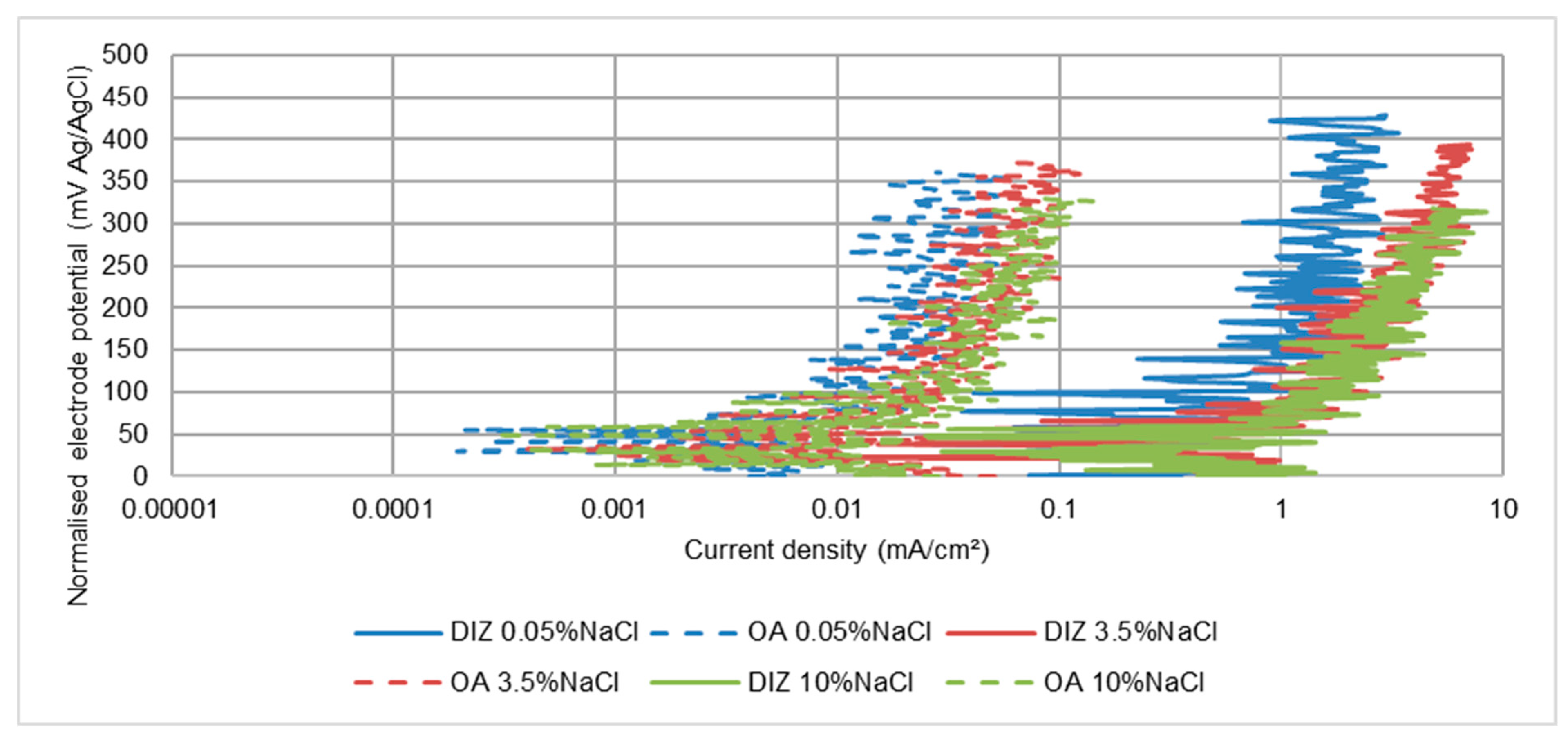
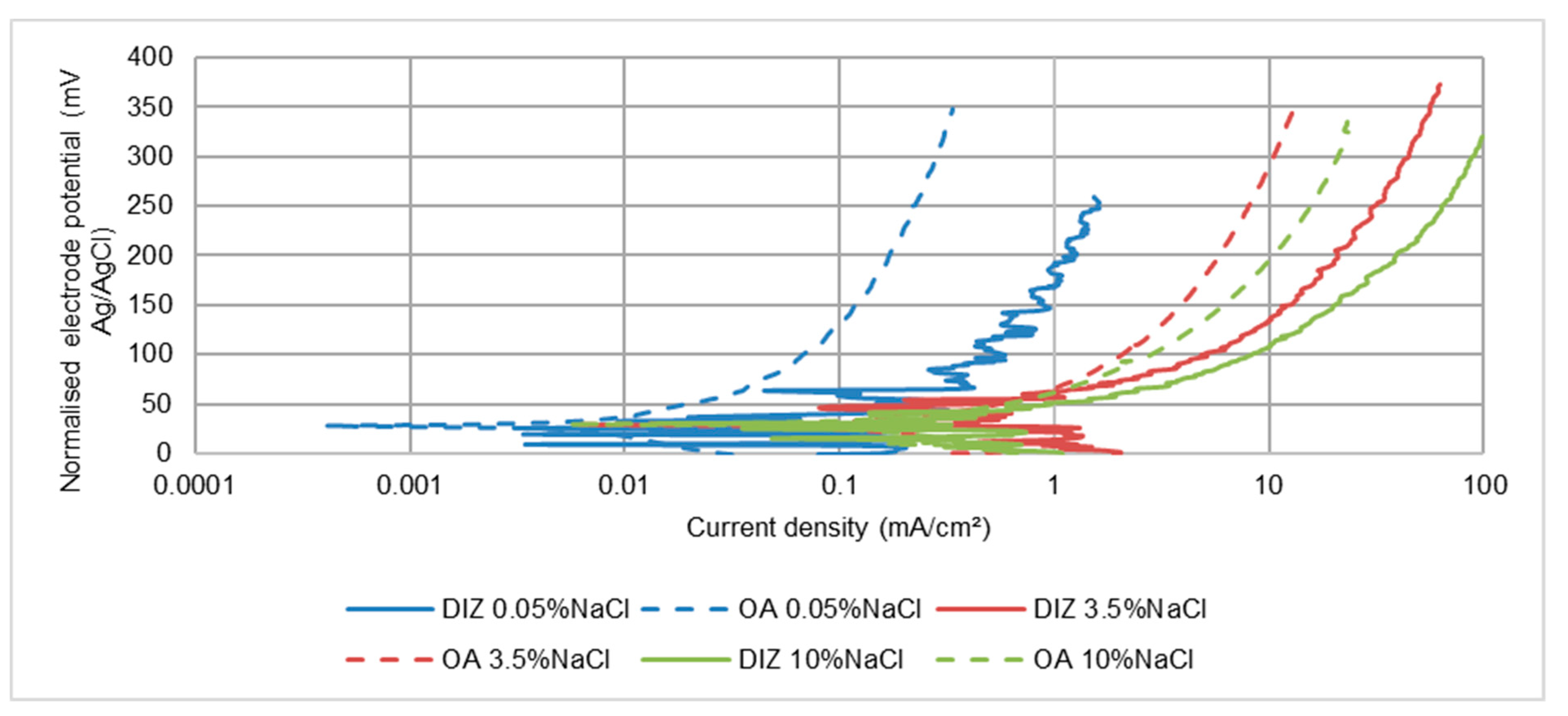
3.3.1. Stainless Steels

The findings are summarised in Table 7, Table 8 and Table 9 and an illustrative set of polarisation plots for UNS S31600 is shown in Figure 13. They reveal substantially higher corrosion rates in the directly-impinged zone (DIZ) compared to the outer zone (OA)–as quantified in Table 10. Figure 13 also displays the alternating passive-film de-passivation/re-passivation behaviour promoted by the impingement of sand particles that has been discussed previously in relation to Figure 7.
Even in the relatively-milder conditions encountered in the OA, fluctuations in the recorded currents (see for UNS S31600, Figure 13) are observed–demonstrating vulnerability of the passive film to periodic de-passivation/re-passivation events. Additionally, in comparison with the data in Table 3, Table 4 and Table 5, the corrosion rates in the DIZ were well in excess (more than 10 times) than for the single specimen. In contrast, the rates in the OA were slightly less than for a single specimen.
The corrosion rates for all three stainless steels reveal that, for both hydrodynamic regions, the effect of salinity is to cause large increases in corrosion rate in 3.5 wt% NaCl solution compared with the lower-salinity water, but a further increase in NaCl concentration from 3.5 wt% NaCl to 10 wt% NaCl resulted in a lower corrosion current density. The erosion-enhanced corrosion factor is substantial in both the DIZ and OA zones.
In comparison with the two other grades of stainless steel, the corrosion rates displayed by the UNS S32760 steel were significantly lower. In addition, the erosion-enhanced corrosion factor was significantly lower in the outer zone for the two highest-salinity slurries.

3.3.2. Low Alloy Steel–UNS G43400

The polarisation plots and calculated corrosion rates for the segmented specimens are displayed in Figure 14 and Table 11 respectively. Another clear distinction between the behaviour of this material and the stainless steels is that the rate of corrosion in the DIZ is only about 2–4 times that in the outer zone. The generally similar influences of salinity to those shown in Table 6 (for a single specimen) are apparent; i.e., a large increase in corrosion rate between 0.05 wt% NaCl and 3.5 wt% NaCl, but a subsequent slight decrease in both DIZ and OA when raising the NaCl concentration to 10 wt% NaCl. The corrosion rate in the DIZ at the lowest salinity was substantially lower than in the OA at the higher salinities which is a clear indication that salt concentration has a more pronounced influence than the severity of the hydrodynamic conditions. In line with the general behaviour of the stainless steels, the erosion-enhanced corrosion factor was predominant–even in the outer zone for the two high-salinity slurries.

4. Discussion

4.1. The Influence of Salinity on Corrosion Rates of Low Alloy Steel–UNS G43400

In relation to the behaviour in static and LEC situations, although detailed descriptions of trends are not appropriate from three salinity points, the overall outcome of this aspect of the investigation is in general accord with other research work. Thus, a measurable increase in corrosion rate was observed when subjecting the steel to a moderately-saline environment (3.5 wt% NaCl). In more brine-like (10 wt% NaCl) saline solutions, however, further increases in corrosion rate were not observed. This finding is in line with a number of other investigations [6,7] on carbon steel and low-alloy steel in air-saturated saline solutions which have reported that the corrosion rate attains a maximum value at about 1–4 wt% NaCl.
The above-mentioned studies [6,7] were undertaken in immersed, non-flowing water at room temperature and the present findings have thus extended the knowledge of similar water-composition trends to much more severe hydrodynamic conditions–especially to those comprising turbulent water containing suspended solids–and at a somewhat higher temperature of 40 °C, which is in line with the findings in the earliest work at 90 °C [16].
There is also a broad correspondence with investigations undertaken in (low-oxygen) CO2–containing saline waters in relation to which several investigators have reported a similar corrosion-rate/salinity relationship–although the stated [8,9,35] corrosion rate maxima vary from very low NaCl concentrations (0.01 wt% NaCl) to about 5 wt% NaCl. This correspondence prevails despite the different cathodic reactions involved in aerated and CO2–containing fluids.
It is obviously of interest to consider possible corrosion mechanisms that might yield these water composition relationships. The usually stated mechanisms [6,7] invoke the influence of salinity in causing opposite trends by increasing the electrical conductivity of the water, but decreasing the oxygen solubility, but these may represent oversimplifications. The notion that higher salinity causes increases in corrosion rate of carbon- and low-alloy steels on account of the elevated conductivity of the water is deceptively simple. It may have relevance where there is a physical separation between anodic and cathodic sites on a component surface–such as, for example, instances of galvanic corrosion. However, in the case of uniform (general surface) corrosion of a single metal, the anodic and cathodic sites are extremely closely-spaced (probably involving atomic distances) with only negligible electrode potential differences between them. Sani et al. [9] have also argued that a simple correlation with the elevated electrical conductivity, and hence increased corrosivity, of saline solutions, appears unsatisfactory.
An alternative interpretation, of the effect of chloride in increasing the corrosion rate in 3.5 wt% NaCl solution, is via a consideration of the constitution of the corrosion products forming on the steel surface. The corrosion products on some low-alloy steels have been reported [36,37] to contain FeOOH which can occur either in the amorphous state or exist in several crystal modifications of which the type which is recognised [36] as providing the most protective corrosion product is α-FeOOH. In chloride-containing environments, however, other forms of FeOOH, β [37] or γ [36] have been reported-both of which provide poor corrosion protection. Such an imperfect corrosion product layer might also result in pitting attack as an additional factor in the observed increased corrosion rates in solutions of 3.5 wt% NaCl.
In terms of the potential influence of dissolved oxygen, reduced oxygen solubility might be expected to decelerate the oxygen-reduction cathodic reaction:
  O 2 + 2 H 2 O + 4 e   4 ( OH )
which predominates in aerated water. In the present study, however, there has been no evidence of a systematic reduction in cathodic reaction rate with increasing NaCl concentration. Moreover, flowing and impinging water is likely to be supersaturated with atmospheric gases and, therefore, not subject to a rate reduction of the cathodic reaction at higher NaCl contents. Additionally, the electrochemical monitoring results, shown herein, point to the action of salinity in affecting the progress of the anodic reaction (Figure 10, Figure 11 and Figure 12). Thus, a more plausible explanation of the reduced low alloy steel corrosion rate in the highest salinity water involves a restriction in the rate of the anodic reaction which is normally written as:
Fe     Fe 2 + + 2 e
But whose detailed mechanism is a multi-stage process involving intermediate steps in which (OH) ions adsorb on bare steel surface. One such process [37] is:
Fe + ( OH )   FeOH +   e
In chloride-containing solutions, alternative adsorption reactions are possible such as [38]:
                  Fe + m ( OH ) + nCl     ( Fe ( OH ) m ( Cl ) n ) 2 m n + 2 e
Or [39]:
Fe + Cl   FeCl +   e
The proposition is that there is a competition between surface adsorption of (OH) and Cl ions [8,9]–with the latter predominating at relatively-high salinity levels and thus leading to a progressively reducing active corrosion rate. Nevertheless, it is evident that further study is required to explain the clearly demonstrated effects of salt content.
From an industrial perspective, irrespective of the uncertainties concerning the detailed mechanisms involved, an unambiguous aspect of this work is that the deleterious feature of salt concentration, causing increases in corrosion rate, does not extend up to the higher salinities associated with the range of industrial activities mentioned in the Introduction section.

4.2. The Influence of Salinity on Corrosion Rates of Stainless Steels

In static and LEC conditions, the corrosion rates were considerably lower than for the low alloy steel. This, of course, is due to the establishment of a passive film on the surface of the stainless steels. The passive corrosion rates did decrease with alloying content from UNS S15500 to UNS S31600 and to UNS S32760. These rates also exhibited increases with salinity–even between the 3.5 wt% NaCl and 10 wt% NaCl contents and especially so for the two lower-grade stainless alloys. It is clear, therefore, that the chloride ion was, to an extent, degrading the protective nature of the passive films. It is relevant to point out that this feature represented an effect of chloride on the uniform (passive) corrosion rate rather than the localised pitting attack that is well-known to be caused by high Cl concentrations [40].
The incidence of pitting under solid-liquid impingement has been studied by various investigators [33,41]. Interesting correlations have emerged from such studies, but they have only been evident, however, in lower-severity conditions (i.e., relatively-low velocity and/or low suspended-solid burdens). The conditions encountered in many industrial situations, simulated by the experimental protocol selected for study by the present authors, reported herein and in previous publications [21,22], are sufficiently aggressive as to involve turbulent conditions to “wash out” any transient pits. Moreover, such turbulence will render the corrosive-wear damage rates well in excess of conditions where pitting is a relevant feature.
The nature and properties of passive films on high-grade materials such as stainless steels have been the subject of abundant investigation over the decades and it is not the objective herein to delve closely into such aspects. Instead the emphasis is on the main aspects of previous work that are relevant to the findings reported herein. Thus, it is accepted [42,43] that the passive films on stainless steels are generally two-layered with the inner stratum being Cr-rich and the outer layer containing iron. It is also now known what effects chloride ions have on the passive film. Evidence for the manner in which Cl ions can become incorporated into the body of these extremely-thin surface films has been building up. Thus, it has been demonstrated [8,43] that Cl ions can penetrate the Cr-rich films–although the exact mechanism appears to be still essentially unresolved. It is, clear, however, that higher chloride concentrations in the surrounding aqueous environment will lead to more penetration of the passive film and hence result in a progressive increase in passive corrosion rates–as has been observed in the current work.
In the absence of suspended solids, the stainless steels possess excellent resistance to rapidly-flowing water. In one study [44] several different grades of stainless steel were observed to resist a (solids-free) liquid impingement jet at a velocity as high as 100 m/s without serious attack. However, as shown in Figure 13, the presence of sand particles makes these alloys vulnerable to destruction of the passive film–even in relatively mild hydrodynamic conditions prevailing in the outer region of the segmented specimens. It has been demonstrated [33,45] that, in saline (3.5 wt% NaCl) solutions, if the aqueous fluid carries a sufficient burden of suspended solids and/or is flowing at a velocity in excess of critical magnitudes, it causes the kind of intermittent passive-film breakdown and reformation illustrated in Figure 7 and Figure 8. This factor is clearly linked to the kinetic energy of the impacting particles and the abundance of such impacts. The occurrence of re-passivation is related to the known extremely-short times for a de-passivated site in stainless steel to reform the protective film [46].
An interesting observation in the present study has been that alternating de-passivation/re-passivation behaviour of all the stainless steels under SLEC conditions occurs even in the lowest-salinity medium. This feature demonstrates that the vulnerability to passive-film breakdown, in severe hydrodynamic conditions, is independent of the stainless steel grade and occurs in extremely-low chloride-containing water in which the steel is effectively immune from corrosive attack in less-hydrodynamically-severe conditions. A very noticeable feature of the behaviour of the stainless steel alloys was a substantially greater ratio of corrosion rates in the DIZ:OA; the ratio being between 37–90. In contrast, the analogous ratio for the low alloy steel was only 2–4. This differentiation demonstrates that the overall rates of corrosion of stainless steels are very susceptible to the flow conditions when suspended solids are present. The relatively low rates of attack in the outer zones are nevertheless still clearly exhibiting repetitive de-passivation/re-passivation events. Moreover, as shown in Figure 15 for the UNS S31600 steel, the corrosion rates in the OA are also substantially higher than the corrosion rates in quiescent and LEC conditions in the least-saline water where passive behaviour prevails (see Figure 5 and Figure 6). In the more saline water (Figure 16), however, the corrosion rates in the outer region are no higher than those exhibited in static and LEC conditions. Similar trends were observed with the other two stainless steels and demonstrate a complex interplay between the influences of hydrodynamic conditions and salinity.
In terms of the influence of NaCl concentration on the corrosion behaviour of the stainless steels under SLEC conditions, there was a consistent trend of increased corrosion rates as the salt concentration was raised from 0.05 wt% NaCl to 3.5 wt% NaCl. Similar increases in corrosion rate between freshwater and 3.5 wt% NaCl, during erosion-corrosion of UNS S31603 alloy, have been reported [25]. Additionally, in sliding wear experiments, a maximum corrosion rate of Inconel 625 (UNS N66250) at 3 wt% NaCl has been observed [47]. However, the effect of the further increase in NaCl content to 10% NaCl, was (Table 3 and Table 4) to reduce the corrosion rate of single specimens of the UNS S31600 and UNS S15500 alloys whilst the corrosion rate of the UNS S32760 steel was unchanged (Table 5). Moreover, as shown in Figure 17, no increases in corrosion rates of the segmented specimens were evident (Table 7, Table 8 and Table 9). In the DIZ, all three stainless steels exhibited similar trends wit NaCl concentration.
It does appear that the trends, shown by the plots in Figure 17 in these severe SLEC circumstances, mimics, to a certain extent, the trends exhibited by the low alloy steel as the salt content increases. This correspondence is likely to be associated with the accelerated corrosion rates of stainless steel concomitant upon the change in behaviour from passive to intermittently active-this being more akin to the conduct of the low alloy steel.
Following this line of argument, close inspection of aspects of the polarisation characteristics of the (oxygen reduction) cathodic reaction reveals a factor that could be contributing to the variable corrosion rates of the stainless steels in SLEC conditions. Although it is persuasive to interpret the corrosion behaviour of the stainless steels in SLEC conditions by focusing on the anodic polarisation characteristics, the role of the cathodic reaction in driving corrosion rates at un-filmed sites cannot be ignored. In this respect, there are some interesting findings in this work that point to the influence of the cathodic reaction. The influence, of the surface upon which the oxygen reduction reaction occurs, has been examined by obtaining values of the exchange current densities for the cathodic reaction. Although the mechanisms, and hence the kinetics, of the oxygen reduction reaction are not clearly established on stainless steels and related alloy systems, it appears [48,49] that the processes of O2 reduction are markedly influenced by the surface conditions upon which this cathodic reaction occurs. This aspect has therefore been examined, in the current work, by obtaining values of the exchange current densities for the oxygen reduction reaction. The exchange current density for any electrode reaction, usually denoted by io, is known to represent one of the factors that influence the rate of an electrode reaction due to the effect of the chemical and physical state of the surface upon which the reaction is occurring [50,51]. Alloying elements and oxides that possess high overpotentials (via a reduction in exchange current density) for the cathodic reaction will result in a lowering of the corrosion rate at active sites. Exchange current densities, ioc, for the oxygen reduction reaction (Equation (2) above), were obtained by back extrapolation of the cathodic polarisation plots to a value of the equilibrium electrode potential, Eo, for the oxygen reduction reaction. The latter was calculated using the Nernst equation which yielded a value of approximately +0.5 V with reference to the Ag/AgCl scale. A representative graph is shown in Figure 18.
For quiescent conditions, as shown in Table 12, such back extrapolations yielded values of ioc in the range (2 to 5) × 10−7 mA/cm2 for all three stainless steels irrespective of the salt concentrations. Such similar values arise presumably on account of the cathodic reaction occurring on a passive film surface for all these circumstances and, incidentally, are approximately two orders of magnitude less than ioc values (1 × 10⁻⁵ mA/cm2) measured for the cathodic reaction on the, actively-corroding low alloy steel.
In relation to SLEC conditions, however, the ioc values, produced from analogous extrapolations for these stainless steels in the various saline waters, were higher and more variable–especially between the different grades of stainless steel. This behaviour is interpreted as arising from the fact that, in SLEC conditions, the cathodic reaction is occurring on a constantly-changing, complex, bare-metal/passive-filmed surface associated with the oscillating de-passivation/re-passivation events. Moreover, the “bare metal” part of the sequences involves alloys of different crystal structure and composition. These findings correlate with evidence [48] that the rate of the oxygen reduction reaction on stainless steels was found to be greatest on a cathodically, pre-reduced–as opposed to a passivated–surface.
It is of interest to consider the relative behaviour of the superduplex stainless steel in comparison with the other two, lower-grade, stainless steels. The higher-alloyed types of stainless steel contain larger concentrations of Cr, Mo and N and were developed in the quest to provide superior resistance to passive-film breakdown (improved pitting and crevice corrosion behaviour) in saline waters such as seawater [52,53,54]. The influence of such alloying additions on breakdown of the passive film on superduplex stainless steels at elevated electrode potentials has been recently demonstrated [55]. The current study has shown, however, that such tactics are not substantially successful in preventing breakdown of the passive film in severe impingement conditions, at the open circuit potential, represented by the SLEC environment. Indeed, there are some relevant features relating to the passive film-destruction/re-formation events occurring in solid/liquid impingement conditions and similar processes taking place during pit initiation/re-passivation situations in quiescent water [56]. This is despite the substantially different time frames associated with the two types of corrosion behavior. One aspect of such correlations is the observation that the superduplex steel does partially suppress the extent of such attack by reducing current flows (and hence the metal loss by corrosion) during the de-passivation/re-passivation sequences. In other words, the incorporation of higher contents of the appropriate alloying elements does inhibit, to an extent, the metal loss during de-passivation and stimulates the re-passivation event. This finding represents an interesting correlation with the notions [56] that:
  • The oxide of molybdenum is more stable than the chloride
  • Molybdenum (and tungsten) is known to be a “dissolution moderator” i.e., resists dissolution at an actively-corroding site where the passive film has been disrupted.
Similar beneficial effects have been reported [45,57] in relation to the influence of higher-alloying contents on impingement erosion-corrosion performance of superaustenitic stainless steel. Indeed, it has been suggested [45,57] that there is a correlation between static corrosion behaviour and erosion-corrosion performance; this could only be of an approximate qualitative nature, but the submission is that it could be of some relevance in choice of materials for erosion-corrosion service.

5. Conclusions

This study has revealed that the influence of NaCl concentration on corrosion rates is quite different between low alloy steel and stainless steel in that the relationships are more dependent upon the type of corrosion–active or passive–than on the type of steel.

5.1. Low-Alloy Steel

  • The effects of increasing salinity, reported previously [5,6,7], have been shown in this study to extend to the much-more hydrodynamically-severe situation of an extremely turbulent stream of saline water that contains a burden of suspended particles. Thus, an increase in corrosion rate was observed at moderate salt concentrations followed by a reduction in corrosion rate at higher salt concentrations.
  • The influence of salinity has been shown to affect the progress of the anodic reaction with no evidence being found to support earlier theories that increases in salt content result in a progressively reducing rate of the cathodic reaction. Possible fundamental mechanisms for the anodic reaction trends have been discussed, but no convincing explanations have been identified. Further study is required to explain the clearly demonstrated effects of salt content.
  • The findings using segmented specimens have shown that the influence of salinity on corrosion rates has been observed to be greater than that caused by hydrodynamic changes.

5.2. Stainless Steels

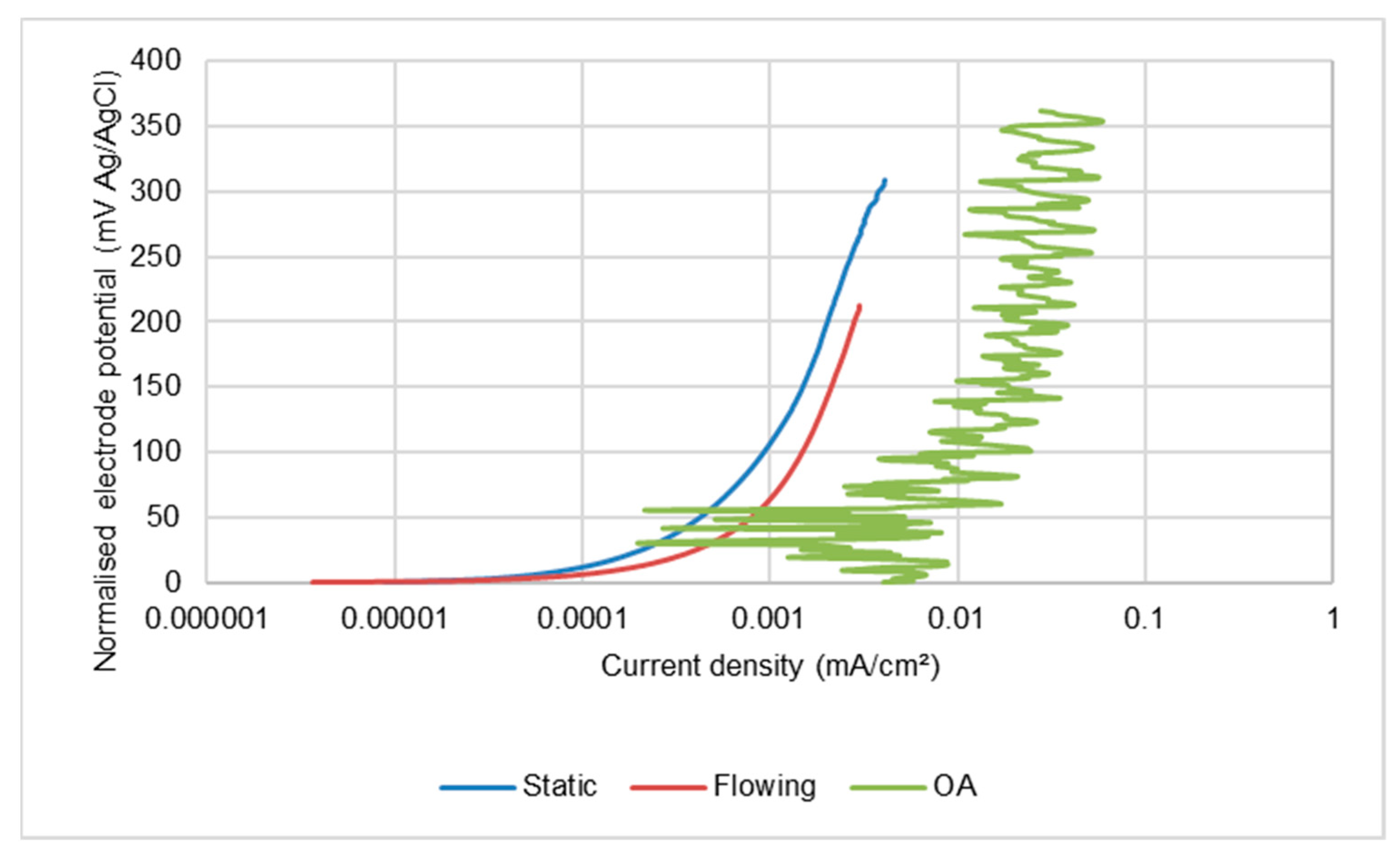
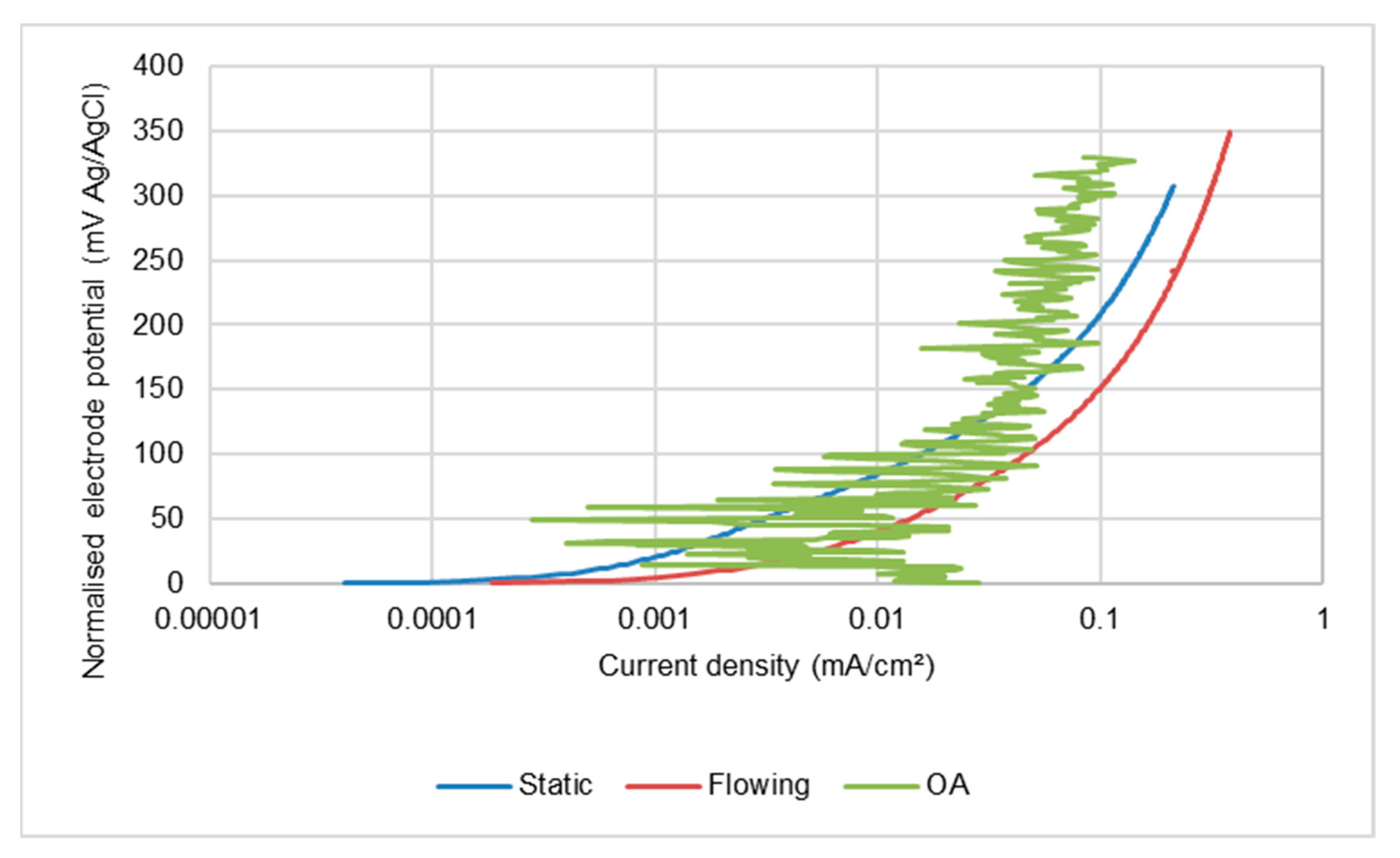
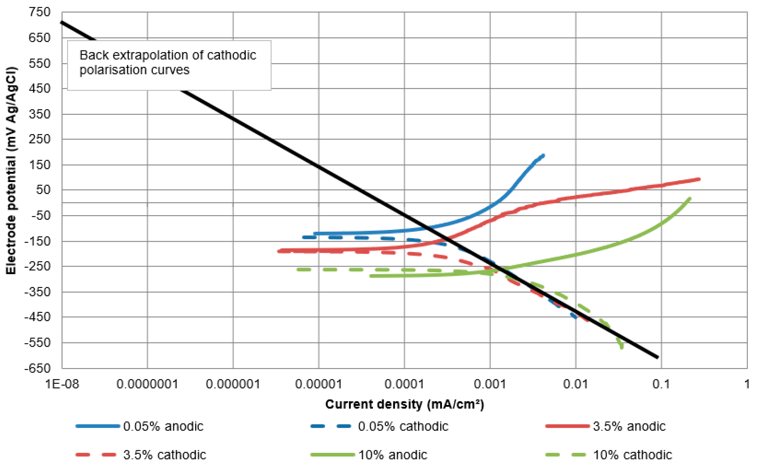
  • For quiescent and liquid impingement (no solids) conditions, i.e., when passive films are present on the surface of the alloy, a continuously increasing rate of corrosion with salinity has been observed. This trend has been rationalised in terms of the well-established feature of increasing adsorption/penetration of the passive oxide films by chloride ions.
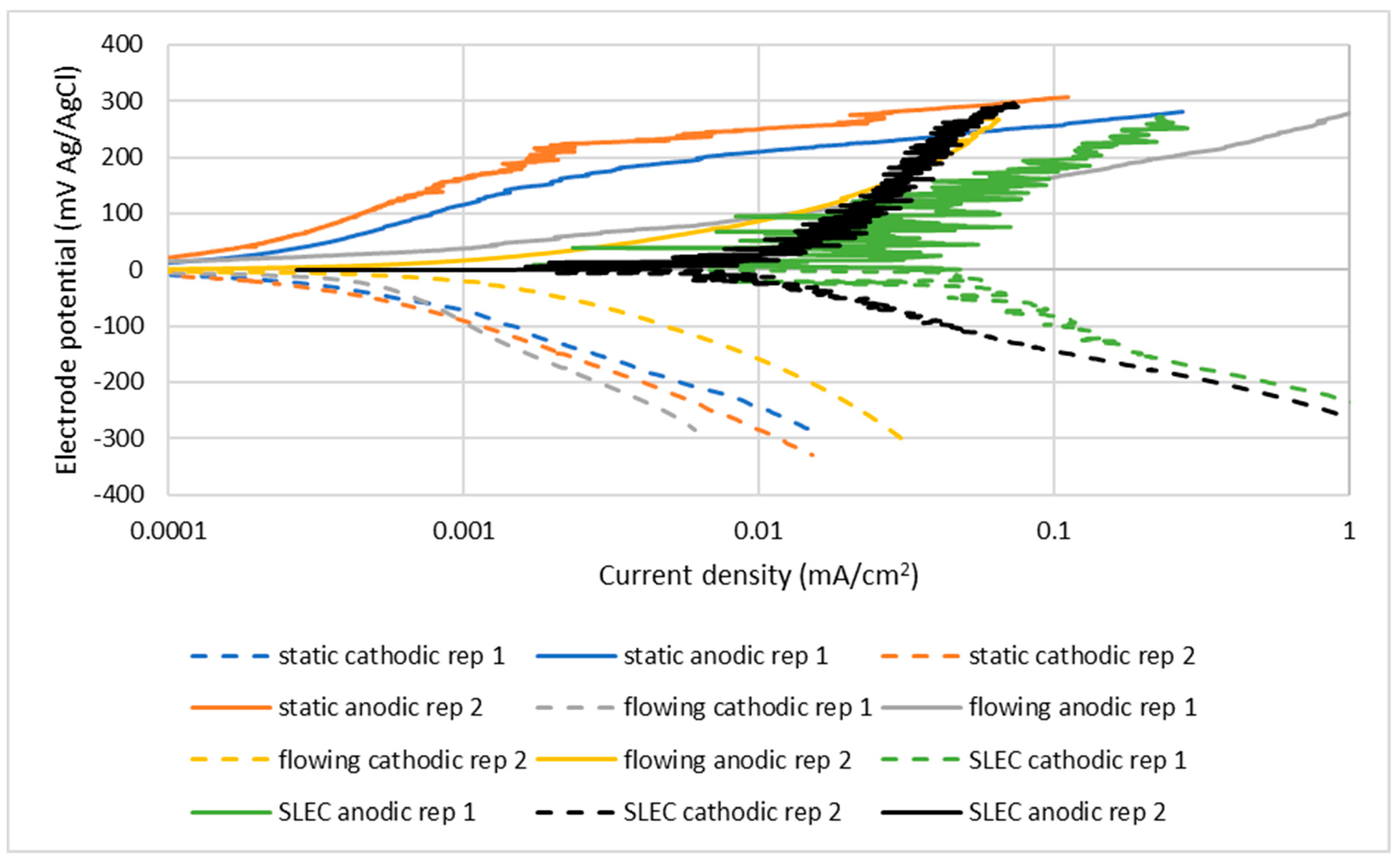
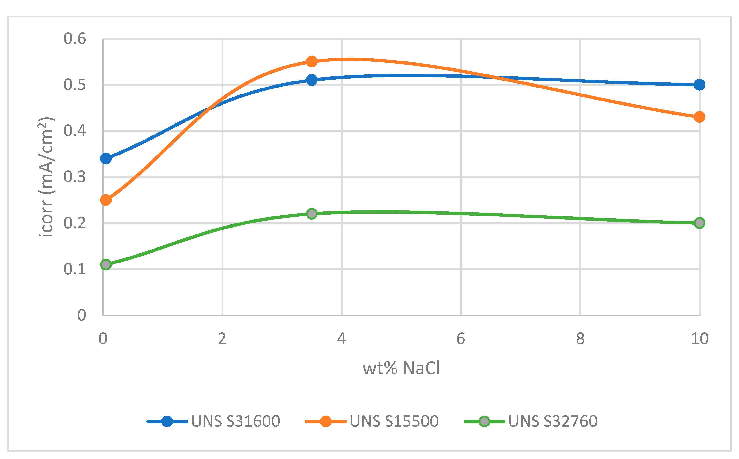
  • In severe solid/liquid impingement, the relationship between corrosion rate and salinity is more complex. A consistent increase in corrosion rate has only been found as the salt concentration changes from 0.05 wt% NaCl to 3.5 wt% NaCl. The corrosion rates in 10 wt% NaCl are either the same or slightly lower than in 3.5 wt% NaCl solution. Thus, the behaviour in SLEC conditions displays some similarities to that of the low alloy steel with the fluctuating de-passivation/re-passivation sequences involving pseudo-active corrosion more akin to that exhibited by a low alloy steel.
  • The stainless steels experience rapidly fluctuating, depassivation/repassivation sequences in both the directly impinged and surrounding regions. The actual corrosion rates are, however, 37–90 times greater in the DIZ segment than those in the outer zone.
  • The corrosion behaviour of the different grades of stainless steel, under solid-liquid impingement, is not related to the metallurgical structure, but is a function of the alloy chemistry–with the highest alloyed grade of stainless steel, UNS S32760, exhibiting the least vulnerability at all salinity levels investigated. This effect is associated with an attenuation of the current transients, during the alternating film destruction/re-passivation, by restricting metal dissolution and promoting re-passivation.
  • To this extent, there is a degree of correlation between corrosive attack on the UNS S32760 steel during aggressive solid/liquid impingement and that involving localised corrosion in less-hydrodynamically-severe conditions.
  • In contrast to the situation with the low alloy steel, exposure of stainless steels to a severe solid-liquid impinging stream has a larger influence than that brought about by changes in NaCl concentration in the water.

5.3. Synergism

  • For all materials in this study, the erosion-enhanced corrosion (synergy) factor has been found to be substantial; always in excess of 50% of the total corrosion rate and, in most cases, larger than 80%.

Author Contributions

Conceptualization, F.B. and T.H.; methodology, F.B. and T.H.; validation, F.B. and T.H.; investigation, F.B.; writing—original draft preparation, T.H.; writing—review and editing, F.B., T.H., A.P. and A.G.; supervision, T.H., A.P. and A.G. All authors have read and agreed to the published version of the manuscript.

Funding

This research was funded by Weir Group PLC, grant number WARC2011-SAA1, 2011.

Institutional Review Board Statement

Not applicable.

Informed Consent Statement

Not applicable.

Data Availability Statement

Data sharing not applicable.

Acknowledgments

The authors would like to acknowledge the support for this study, which was provided by the Weir Group PLC (WARC2011- SAA1, 2011) via its establishment of the Weir Advanced Research Centre (WARC) at the University of Strathclyde.

Conflicts of Interest

The authors declare no conflict of interest.

References

  1. Abdou, M.; Carbegie, A.; Matthews, S.G.; McCarthy, K.; O’Keefe, B.; Raghuraman, B.; Wei, W.; Xian, C. Finding value in formation water. Oilfield Rev. 2011, 23, 24–35. [Google Scholar]
  2. Rassenfoss, S. From flowback to fracturing water recycling grows in the Marcellus shale. J. Pet. Technol. 2011, 63, 48–51. [Google Scholar] [CrossRef]
  3. Haibin, L.; Zhenling, L. Recycling utilization patterns of coal mining water in China. Resour. Conserv. Recycl. 2010, 54, 1331–1340. [Google Scholar] [CrossRef]
  4. Estrada, J.M.; Bhamidimarri, R. A review of the issues and treatment options for wastewater from shale gas extraction by hydraulic fracturing. Fuel 2016, 54, 292–303. [Google Scholar] [CrossRef]
  5. Montes, C.; Cantallopts, J.Ç. Proyección de Consumo de Agua En La Minería Del Cobre 2018–2029; Comision Chilena del Cobre: Santiago, Chile, 2018. [Google Scholar]
  6. Revie, R.W.; Uhlig, H.H. Corrosion and Corrosion Control: An Introduction to Corrosion Science and Engineering, 4th ed.; John Wiley & sons, Inc.: Hoboken, NJ, USA, 2008; pp. 151–152. [Google Scholar]
  7. Cheng, P.; Huang, X. Effect of Salinity on Corrosion Behavior of DH36 Steel in Seawater Immersion Zone, APETC 2017; DEStech Publications, Inc.: Lancaster, PA, USA, 2017; pp. 1219–1223. [Google Scholar]
  8. Zeng, Z.; Lillard, R.S.; Cong, H. Effect of salt concentration on the corrosion behavior of carbon steel in CO2 environment. Corrosion 2016, 72, 805–823. [Google Scholar] [CrossRef]
  9. Sani, F.M.; Brown, B.; Belarbi, Z.; Nesic, S. An Experimental Investigation on the Effect of Salt Concentration on Uniform CO2 Corrosion, CORROSION 2019; Paper No. 13026; NACE International: Houston, TX, USA, 2019. [Google Scholar]
  10. Fang, H.; Brown, B.; Nesic, S. High Salt Concentration Effects on CO2 Corrosion and H2S Corrosion, CORROSION 2010; Paper No. 10276; NACE International: Houston, TX, USA, 2010. [Google Scholar]
  11. Davison, R.M.; Laurin, T.R.; Redmund, J.D.; Watanabe, H.; Semchyshen, M. A review of worldwide developments in stainless steels. Mater. Des. 1986, 7, 111–118. [Google Scholar] [CrossRef]
  12. Lee, J.-B. Effects of alloying elements, Cr, Mo and N on repassivtion characteristics of stainless steels using the abrading electrode technique. Mater. Chem. Phys. 2006, 99, 224–234. [Google Scholar] [CrossRef]
  13. Olsson, J. Stainless steels for desalination plants. Desalination 2005, 183, 217–225. [Google Scholar] [CrossRef]
  14. Magdy, A.M.; Ibrahim, S.S.; Abd El Rehim, M.M. Corrosion behavior of some austenitic stainless steels in chloride environments. Mater. Chem. Phys. 2009, 115, 80–85. [Google Scholar]
  15. Malik, A.U.; Mayan Kutty, P.C.; Siddiqui, N.A.; Andijani, I.N.; Ahmed, S. The influence of pH and chloride concentration on the corrosion behaviour of AISI 316L steel in aqueous solutions, solutions. Corros. Sci. 1992, 33, 1809–1827. [Google Scholar] [CrossRef]
  16. Uhlig, H.H.; Morrill, M.C. Corrosion of 18-8 stainless steel in sodium chloride solutions. Ind. Eng. Chem. 1941, 33, 875–880. [Google Scholar] [CrossRef]
  17. Walker, C.I. Slurry pump side-liner wear: Comparison of some laboratory and field results. Wear 2001, 250, 81–87. [Google Scholar] [CrossRef]
  18. Tang, X.; Xu, L.Y.; Cheng, Y.F. Electochemical corrosion behavior of X-65 steel in the simulated oil-sand slurry. II: Synergism of erosion and corrosion. Corros. Sci. 2008, 50, 1469–1474. [Google Scholar] [CrossRef]
  19. Aguirre, J.; Walczak, M.; Rohwerder, M. The mechanism of erosion corrosion of API X65 steel under turbulent slurry flow: Effect of nominal flow velocity and oxygen content. Wear 2019, 438–439, 203053. [Google Scholar] [CrossRef]
  20. Lu, B.T.; Luo, J.L. Correlation between surface-hardness degradation and erosion resistance of carbon steel—Effects of slurry chemistry. Tribol. Int. 2015, 83, 146–155. [Google Scholar] [CrossRef]
  21. Giourntas, L.; Hodgkiess, T.; Galloway, A.M. Comparative study of erosion-corrosion performance on a range of stainless steels. Wear 2015, 332–333, 1051–1058. [Google Scholar] [CrossRef] [Green Version]
  22. Brownlie, F.; Hodgkiess, T.; Pearson, A.; Galloway, A.M. Effect of nitriding on the corrosive wear performance of a single and double layer Stellite 6 weld cladding. Wear 2017, 376–377, 1279–1285. [Google Scholar] [CrossRef] [Green Version]
  23. Neville, A.; Hodgkiess, T. Characterisation of high-grade alloy behavior in severe erosion-corrosion conditions. Wear 1999, 233–235, 596–607. [Google Scholar] [CrossRef]
  24. Meng, A.; Hu, X.; Neville, A. A systematic erosion-corrosion study of two stainless steels in marine conditions via experimental design. Wear 2007, 263, 355–362. [Google Scholar] [CrossRef]
  25. Neville, A.; Hodgkiess, T. Study of effect of liquid corrosivity in liquid-solid impingement on cast iron and austenitic stainless steel. Br. Corros. J. 1997, 32, 197–205. [Google Scholar] [CrossRef]
  26. Neville, A.; Hodgkiess, T.; Xu, H. An electrochemical and microstructural assessment of erosion-corrosion of cast iron. Wear 1999, 233–235, 523–534. [Google Scholar] [CrossRef]
  27. Smith, F.; Brownlie, F.; Hodgkiess, T.; Pearson, A.; Galloway, A.M. Effect of salinity on the corrosive wear behaviour of engineering steels in aqueous solutions. Wear 2020, 462–463, 203515. [Google Scholar] [CrossRef]
  28. Brownlie, F.; Hodgkiess, T.; Pearson, A.; Galloway, A.M. Erosion-Corrosion Mechanisms of Engineering Steels in Different NaCl Concentrations. J. Bio- Tribo-Corros. 2021, 7, 80. [Google Scholar] [CrossRef]
  29. Giourntas, L.; Hodgkiess, T.; Galloway, A.M. Enhanced approach of assessing the corrosive wear of engineering materials under impingement. Wear 2015, 338–339, 155–163. [Google Scholar] [CrossRef] [Green Version]
  30. Brownlie, F.; Anene, C.; Hodgkiess, T.; Pearson, A.; Galloway, A.M. Comparison of hot wire TIG Stellite 6 weld cladding and lost wax Stellite 6 under corrosive wear conditions. Wear 2018, 404–405, 71–81. [Google Scholar] [CrossRef] [Green Version]
  31. West, J.M. Basic Corrosion and Oxidation, 2nd ed.; Ellis Horwood: Chichester, UK, 1986; pp. 79–83. [Google Scholar]
  32. ASTM G119-09; Standard Guide for Determining Synergism between Wear and Corrosion. ASTM: West Conshohocken, PA, USA, 2016.
  33. Zheng, Z.B.; Zheng, Y.G. Erosion enhanced corrosion of stainless steel and carbon steel measured electrochemically under liquid and slurry impingement. Corros. Sci. 2016, 102, 259–268. [Google Scholar] [CrossRef]
  34. Gnanavelu, A.; Kapur, N.; Neville, A.; Flores, J.F. An integrated methodology for predicting material wear rates due to erosion. Wear 2009, 267, 1935–1944. [Google Scholar] [CrossRef]
  35. Kanimozhi, K.R.; Shyamala, R.; Papavinasam, S.; Li, J. Effect of Sodium Concentration on the Corrosion of Carbon Steels and Stainless Steels in CO2 Environment at Atmospheric Pressure under Turbulent Flow Conditions, CORROSION 2014; Paper No. 4074; NACE International: Houston, TX, USA, 2014. [Google Scholar]
  36. Liu, P.; Hu, L.; Zhao, X.; Zhang, Q.; Yu, Z.; Hu, J.; Chen, Y.; Wu, F.; Cao, F. Investigation of microstructure and corrosion behavior of weathering steel in aqueous solutions containing different anions for simulating service environments. Corros. Sci. 2020, 170, 108686. [Google Scholar] [CrossRef]
  37. Ishikawa, T.; Katoh, R.; Yasukawa, A.; Kandori, K.; Nakayama, T.; Yuse, F. Influences of metalions on the formation of β-FeOOH particles. Corros. Sci. 2001, 43, 1727–1738. [Google Scholar] [CrossRef]
  38. Asakura, S.; Nobe, K. Electrodissolution kinetics of iron in chloride solutions Part II: Alkaline solutions. J. Electrochem. Soc. 1971, 118, 19–22. [Google Scholar] [CrossRef]
  39. Burstein, G.T.; Davies, D.H. The effects of anions on the behavior of scratched iron elevtrodes in aqueous solutions. Corros. Sci. 1980, 20, 1143–1155. [Google Scholar] [CrossRef]
  40. Deng, S.; Wang, S.; Wang, L.; Liu, J.; Wang, Y. Influence of chloride on passive film chemistry of 304 stainless steel in sulphuric acid solution by glow discharge optical emission spectrometry analysis. J. Electrochem. Sci. 2017, 12, 1106–1117. [Google Scholar] [CrossRef]
  41. Sasaki, K.; Burstein, G.T. The generation of surface roughness during slurry erosion-corrosion and its effect on the pitting potential. Corros. Sci. 1996, 38, 2111–2120. [Google Scholar] [CrossRef]
  42. Olsson, C.-O.A.; Landolt, D. Passive films on stainless steels—Chemistry, structure and growth. Electrochim. Acta 2003, 48, 1093–1104. [Google Scholar] [CrossRef]
  43. Zhang, B.; Wang, J.; Wu, B.; Guo, X.W.; Wang, Y.J.; Chen, D.; Zhang, Y.C.; Du, K.; Oguzie, E.E.; Ma, X.L. Unmasking chloride attack on the passive film of metals. Nat. Commun. 2018, 9, 2559. [Google Scholar] [CrossRef] [PubMed]
  44. Neville, A.; Hodgkiess, T. An assessment of the corrosion behavior of high-grade alloys in seawater at elevated temperatures and under a high velocity impinging flow. Corros. Sci. 1996, 38, 927–956. [Google Scholar] [CrossRef]
  45. Hu, X.; Neville, A. The electrochemical response of stainless steels in liquid-solid impingement. Wear 2005, 258, 641–648. [Google Scholar] [CrossRef]
  46. Rajahram, S.S.; Harvey, T.J.; Wood, R.J.K. Electrochemical investigation of erosion-corrosion using a slurry pot erosion tester. Tribol. Int. 2011, 44, 232–240. [Google Scholar] [CrossRef]
  47. Chen, J.; Wang, J.; Chen, B.; Yan, F. Tribocorrosion behaviours of Inconle 625 alloy sliding against 316 steel in seawater. Tribol. Trans. 2011, 54, 514–522. [Google Scholar] [CrossRef]
  48. Le Bozec, N.; Compere, C.; L’Her, M.; Laouenan, A.; Costa, D.; Marcus, P. Influence of stainless srteel surface treatment on the oxygen refuction reaction in seawater. Corros. Sci. 2001, 43, 765–786. [Google Scholar] [CrossRef]
  49. Davydov, A.; Rybalka, K.V.; Beketaeva, L.A.; Engelhardt, G.R.; Jayaweera, P.; Macdonald, D.D. The kinetics of hydrogen evolution and oxygen reduction on Alloy 22. Corros. Sci. 2005, 47, 195–215. [Google Scholar] [CrossRef]
  50. O’M Bockris, J.; Reddy, A.K.N. Modern Electrochemistry: Volume 2; Plenum Press: New York, NY, USA, 1977; pp. 876–879. [Google Scholar]
  51. Vetter, K.J. Electrochemical Kinetics: Theoretical and Experimental Aspects; Academic Press: New York, NY, USA, 1967; pp. 9–10. [Google Scholar]
  52. Francis, R.; Hebdon, S. The Selection of Stainless Steels for Seawater Pumps, CORROSION 2015; Paper No. 5446; NACE International: Houston, TX, USA, 2015. [Google Scholar]
  53. Chen, L.; Tan, H.; Wang, Z.; Li, J.; Jiang, Y. Influence of cooling rate on microstructure evolution and pitting corrosion resistance in the simulated heat-affected zone of 2304 duplex stainless steels. Corros. Sci. 2012, 58, 168–174. [Google Scholar] [CrossRef]
  54. Merello, R.; Botana, F.J.; Botella, J.; Matres, M.V.; Marcos, M. Influence of chemical composition on the pitting corrosion resistance of non-standard low-Ni high-Mn-N duplex stainless steels. Corros. Sci. 2003, 45, 909–921. [Google Scholar] [CrossRef]
  55. Langberg, M.; Ornek, C.; Evertsson, J.; Harlow, G.S.; Linpe, W.; Rullik, L.; Carla, F.; Felici, R.; Bettini, E.; Kivisakk, U.; et al. Redefining passivity breakdown of super duplex stainless steel by electrochemical operando synchrotron near surface X-ray analyses. Mater. Degrad. 2019, 3, 22. [Google Scholar] [CrossRef]
  56. Taylor, C.D.; Lu, P.; Saal, J.; Frankel, G.S.; Scully, J.R. Integrated computational materials engineering of corrosion resistant alloys. Mater. Degrad. 2018, 2, 6. [Google Scholar] [CrossRef]
  57. Majeed, M.N. Understanding the Erosion-Corrosion Behavior of Generic Types of Stainless Steels in a CO2-Saturated Oilfield Environment. Ph.D. Thesis, University of Leeds, Leeds, UK, 2018. [Google Scholar]
Figure 1. Schematic representation of recirculating, submerged-impingement, slurry-jet test rig.
Cmd 03 00006 g001
Figure 2. Size distribution of sand particles.
Cmd 03 00006 g002
Figure 3. Segmented sample encapsulated in epoxy resin.
Cmd 03 00006 g003
Figure 4. Example of duplicate polarisation plots for UNS S31600 in 3.5% NaCl.
Cmd 03 00006 g004
Figure 7. Polarisation plots for UNS S31600 in impinging solution containing sand particles (SLEC).
Cmd 03 00006 g007
Figure 8. Polarisation plots UNS S32760 in impinging solution containing sand particles (SLEC).
Cmd 03 00006 g008
Figure 9. Polarisation plots for UNS G43400 steel in quiescent conditions.
Cmd 03 00006 g009
Figure 10. Polarisation plots for UNS G43400 steel under LEC conditions (no solids).
Cmd 03 00006 g010
Figure 11. Polarisation plots for UNS G43400 steel in SLEC conditions.
Cmd 03 00006 g011
Figure 12. Comparison of the corrosion behaviour of the alloys in SLEC, 10% NaCl conditions.
Cmd 03 00006 g012
Figure 13. Anodic polarisation plots for segmented UNS S31600 stainless steel specimens in SLEC conditions.
Cmd 03 00006 g013
Figure 14. Polarisation plots for segmented UNS G43400 steel specimens in SLEC conditions.
Cmd 03 00006 g014
Figure 15. Comparison of anodic polarisation behaviour in 0.05% NaCl of UNS S31600 alloy in outer zone of SLEC specimen with those in static and LEC conditions.
Cmd 03 00006 g015
Figure 16. Comparison of anodic polarisation behaviour in 10% NaCl of UNS S31600 alloy in outer zone of SLEC specimen with those in static and LEC conditions.
Cmd 03 00006 g016
Figure 17. Trends in corrosion rate of directly-impinged zone.
Cmd 03 00006 g017
Figure 18. Illustration of back extrapolation of cathodic polarisation plots to Eo for the oxygen reduction reaction for UNS S31600 in static conditions.
Cmd 03 00006 g018
Table 1. Nominal chemical compositions (wt%) of the tested materials.
MaterialCCrNiMnSiMoSNPCuWNbFe
UNS G434000.37–0.430.7–0.91.65–20.6–0.80.15–0.30.2–0.30.04-0.035---Bal.
UNS S155000.07 max.14–15.53.5–5.51 max.1 max.-0.03 max.-0.042.5–4.5-0.15–0.45Bal.
UNS S316000.08 max.16–1810–142 max.0.75 max.2–30.03 max.0.1 max.0.045 max.---Bal.
UNS S327600.03 max.24–266–81 max.1 max.3–40.01 max.0.2–0.30.03 max.0.5–10.5–1-Bal.
Table 2. Measured hardness of the tested materials.
MaterialHardness (HV–5 kgf)
UNS G43400300
UNS S15500360
UNS S31600170
UNS S32760265
Table 4. Corrosion rates of UNS S15500 in the different hydrodynamic conditions.
wt% NaClStaticLiquid Impingement (LEC)
Ecorr (mV)Icorr (mA/cm2)
Measurements
Icorr (mA/cm2)
Average
Ecorr (mV)Icorr (mA/cm2)
Measurements
Icorr
(mA/cm2)
Average
0.05−1390.001, 0.00040.0007−1120.002, 0.00060.0013
3.5−2690.002, 0.0020.002−2870.005, 0.0050.005
10−2670.004, 0.0060.005−3140.009, 0.0100.010
SLEC
wt% NaClEcorr (mV)Icorr (mA/cm2)
measurements
Icorr (mA/cm2)
average
Erosion-enhanced corrosion
Icorr (mA/cm2)
Erosion-enhanced corrosion, % of Icorr
SLEC
0.05−4040.010, 0.010.0100.009393
3.5−3590.022, 0.0230.0230.02191
10−3990.016, 0.0280.0220.01777
Table 5. Corrosion rates of UNS S32760 in the different hydrodynamic conditions.
wt% NaClStaticLiquid Impingement (LEC)
Ecorr (mV)Icorr (mA/cm2)Icorr (mA/cm2)Ecorr (mV)Icorr (mA/cm2)Icorr (mA/cm2)
MeasuredAverageMeasuredAveraage
0.05−1380.0003, 0.0003, 0.0003−620.0005, 0.00070.0006
3.5−2470.0016, 0.00200.0018−2900.002, 0.0080.0050
10−2370.0022, 0.00500.0036−2650.0035, 0.00550.0045
SLEC
wt% NaClEcorr (mV)Icorr (mA/cm2)Icorr (mA/cm2)Erosion-enhanced corrosion Erosion-enhanced corrosion, % of
measuredAverageIcorr (mA/cm2)Icorr SLEC
0.05−4120.002, 0.007 0.0050.004794
3.5−4000.003, 0.015 0.0090.007280
10−4190.003, 0.015 0.0090.006464
Table 6. Corrosion rates of UNS G43400 low-alloy steel in the different hydrodynamic conditions.
wt% NaClStaticLEC
Ecorr (mV)Icorr (mA/cm2)
Measured
Icorr (mA/cm2) AverageEcorr (mV)Icorr (mA/cm2) MeasuredIcorr (mA/cm2)
Average
0.05−5740.025, 0.0250.025−4030.025, 0.0400.033
3.5−6620.04, 0.050.045−5610.50, 0.170.34
10−6370.05, 0.040.045−5470.17, 0.500.34
SLEC
wt% NaClEcorr
(mV)
Icorr (mA/cm2) measuredIcorr (mA/cm2) averageErosion-enhanced corrosion
Icorr (mA/cm2)
Erosion-enhanced corrosion
% of Icorr SLEC
0.05−3930.030, 0.0750.0530.02853
3.5−5300.70, 1.301.000.95596
10−5420.80, 1.201.000.95596
Table 7. Electrochemical measurements for UNS S31600 segmented sample in all test salinities.
DIZ (0.2 cm2)OA (11 cm2)
Ecorr
(mV)
Icorr
(mA/cm2) Measured
Icorr
(mA/cm2) Average
∆CE (mA/cm2)Ecorr
(mV)
Icorr
(mA/cm2)
Measured
Icorr
(mA/cm2)
Average
∆CE
(mA/cm2)
0.05 wt% NaCl−3800.08, 0.600.340.349−4070.002, 0.0150.0090.0087
3.5 wt% NaCl−4370.09, 1.000.510.510−4370.002, 0.0250.0140.0137
10 wt% NaCl−4190.20, 0.800.500.498−4330.002, 0.0150.0090.0072
Table 8. Electrochemical measurements for UNS S15500 alloy segmented sample in all test salinities.
DIZ (0.2 cm2)OA (11 cm2)
Ecorr
(mV)
Icorr
(mA/cm2) Measured
Icorr
(mA/cm2) Average
∆CE
(mA/cm2)
Ecorr
(mV)
Icorr
(mA/cm2) Measured
Icorr
(mA/cm2) Average
∆CE
(mA/cm2)
0.05 wt% NaCl−4140.10, 0.400.250.249−4070.002, 0.0070.00450.0039
3.5 wt% NaCl−4380.30, 0.800.550.548−4370.010, 0.0200.0150.013
10 wt% NaCl−4370.06, 0.800.430.795−4330.010, 0.0200.0150.010
Table 9. Electrochemical measurements for UNS S32760 segmented sample in all test salinities.
DIZ (0.2 cm2)OA (11 cm2)
Ecorr
(mV)
Icorr
(mA/cm2) Measured
Icorr
(mA/cm2) Average
∆CE
(mA/cm2)
Ecorr
(mV)
Icorr
(mA/cm2) Measured
Icorr
(mA/cm2) Average
∆CE
(mA/cm2)
0.05 wt% NaCl−5250.06, 0.150.110.107−3800.002, 0.0050.00350.0032
3.5 wt% NaCl−5220.03, 0.400.220.247−3120.0008, 0.0080.0070.0052
10 wt% NaCl−5460.05, 0.350.200.293−3500.002, 0.0050.00350.000
Table 10. Relative corrosion rates in DIZ and OA.
MaterialRatio of Corrosion Rate in DIZ:OA
UNS S3160050–90
UNS S1550037–53
UNS S3276050–75
Table 11. Electrochemical measurements for UNS G43400 segmented sample in all test salinities.
DIZ (0.2 cm2)OA (11 cm2)
Ecorr
(mV)
Icorr
(mA/cm2) Measured
Icorr
(mA/cm2) Average
∆CE
(mA/cm2)
Ecorr
(mV)
Icorr
(mA/cm2) Measured
Icorr
(mA/cm2) Average
∆CE
(mA/cm2)
0.05 wt%
NaCl
−4700.07, 0.180.130.085−4210.03, 0.060.0450.020
3.5 wt%
NaCl
−5532.60, 3.002.802.755−5301.00, 1,061.030.985
10 wt% NaCl−5902.00, 2.802.402.355−5550.70, 1.301.000.905
Table 12. Average exchange current densities for the cathodic reactions on stainless steels in quiescent and SLEC conditions.
Stainless Steel Gradeiox (mA/cm2) QUIESCENTiox (mA/cm2) SLEC
UNS S316001.5 × 10−75 × 10−6
UNS S155004.5 × 10−76 × 10−7
UNS S327603 × 10−76 × 10−7
Publisher’s Note: MDPI stays neutral with regard to jurisdictional claims in published maps and institutional affiliations.

