Article

Acoustical Treatments on Ventilation Ducts through Walls: Experimental Results and Novel Models

by
Erik Nilsson
1,*,
Sylvain Ménard
1,
Delphine Bard Hagberg
2 and
Nikolaos-Georgios Vardaxis
2
1
Department of Applied Sciences, University of Québec at Chicoutimi, Chicoutimi, QC G7H2B1, Canada
2
Division of Engineering Acoustics, Lund University, P.O. Box 118, 221 00 Lund, Sweden
*
Author to whom correspondence should be addressed.
Submission received: 1 March 2022 / Revised: 14 March 2022 / Accepted: 16 March 2022 / Published: 18 March 2022

Abstract

:
Sound reduction is complex to estimate for acoustical treatments on ventilation ducts through walls. Various acoustical treatments are available for ventilation ducts, including internal lining (absorption along the inner perimeter), external lagging (external sound insulation), silencer, and suspended ceilings. Previous studies have examined how silencers and the internal lining affect the sound transmission of ventilation ducts. However, there are few theories to predict the effect of external lagging in combination with ventilation ducts and how the total sound reduction is affected. This article aims to investigate different acoustical treatments and develop theoretical models when external lagging with stone wool is used to reduce flanking sound transmission via the surface area of ventilation ducts. Theoretical models are developed for external lagging and compared with measurement data. Measurements and theory are generally in good agreement over the third-octave band range of 100–5000 Hz. The developed models clarify that the distance closest to the wall has the main impact on sound reduction for a combined system with a wall and a ventilation duct. Suspended ceilings and silencers are found to be enough as acoustical treatments for certain combinations of ventilation ducts and walls. However, external lagging seems to be the only effective solution in offices and schools when a large ventilation duct passes through a wall with high sound reduction.

1. Introduction

Ventilation ducts usually have a significant impact on a wall’s sound reduction and treatments are often required to fulfill different acoustic regulations. In a previous study [1], the authors provide updated models for calculating the sound reduction index of circular and rectangular ventilation ducts through walls with different sound reduction indices, without treatment. The theory in [1] is based on laboratory measurements from a previous work by the first author [2] and the models show good agreement with measurements. The amount of acoustical treatment increases with the dimension of the ventilation ducts and with the sound reduction index of the wall. There are various treatments that a designer can choose to reduce the flanking path that arises when a ventilation duct is mounted through a wall. The treatments should be adapted to the problem that needs to be solved.
When sound travels via the ventilation duct, it can travel via both the material and the air inside the duct. In this article, sound attenuation is defined as the damping of sound by the air and by the material on the inside of the duct, and sound transmission is defined as the transfer of sound between different rooms; thus, sound attenuation is a part of the sound transmission. The sound can also travel between rooms via the slit between the ventilation duct and the wall.
The first important treatment is to minimize the leakage in the connection between the ventilation duct and the wall with a sealant. Otherwise, if a slit-shaped aperture is left untreated, the sound reduction will decrease significantly. Westerberg [3] performed measurements on how the sound reduction of a wall with no leakage is reduced when a pipe is mounted through a wall with a wooden cylinder. The wooden cylinder, mounted in the middle of the pipe, had a smaller diameter than the pipe itself, thus creating a slit-shaped circular aperture between the cylinder and the pipe. The article shows reduced sound insulation at higher frequencies with leakage. Yang et al. [4] analyzed the sound transmission of an opening with and without an acoustic sealant. They concluded that an acoustic sealant increases the sound reduction at the off-resonance frequencies of the system. Several studies have also investigated circular and slit-shaped apertures [5,6,7,8].
Sound attenuation can increase by installing an internal lining (absorption) along the inner perimeter of the ventilation duct. The inner lining acts as an absorber, which thereby decreases the sound transmission between rooms if they share the same ventilation duct. The acoustic performance of duct lining depends on several factors, including the geometry of the duct, the placement of the lining, and the acoustic properties of the lining material [9]. Generally, there are two types of lining materials: locally reacting and bulk-reacting linings. The difference between them is the number of directions that the liners permit propagation; locally reacting linings permit propagation only in the direction normal to the duct and bulk-reacting linings permit propagation in more than one direction [9]. The sound attenuation in ducts with linings is investigated in several studies [10,11,12,13,14,15]. Bibby and Hodgson [16] concluded that the lining thickness does not affect high-frequency performance. The thickness mainly affects the low-frequency area, and a 25 mm thick liner is not effective enough [16]. Bibby and Hodgson [16] also concluded that a 100 mm thick liner might be excessive. The use of internal lining as a treatment is appropriate in many scenarios since it affects both the sound attenuation and the sound transmission.
Another method to increase the sound attenuation is with silencers. The use of silencers is also an effective way to reduce the transmission of sound between rooms because they act both as an absorbing material for air circulating inside and reduce the sound traveling through the material. Three different types of HVAC duct silencers are used according to ASHRAE [17] and they are named dissipative, reactive, and active. Dissipative silencers typically use perforated metal to cover an acoustic grade fiberglass. Reactive silencers use tuned perforated metal to cover tuned chamber voids with fibrous material. Lastly, active duct silencers produce inverse sound waves to cancel the unwanted noise, typically for low frequencies [17]. Several articles describe the methods to calculate the transmission or insertion loss in silencers [18,19,20,21,22,23], although ASHRAE [17] states that data should be obtained from measurements according to ASTM E477 [24] for dissipative and reactive silencers when used in calculations.
With a suspended ceiling, sound transmission through ventilation ducts is reduced since they are usually placed above the ceiling. The sound transmission of suspended ceilings is dependent on the thickness, the density, and the porosity of the ceiling material. Laboratory measurements can determine how much the sound transmission decreases between two rooms with a common plenum (volume above the suspended ceiling) depending on the used suspended ceiling. ISO 10848-2 [25] describes this with a weighted normalized sound level difference for suspended ceilings named D n , c , w . ASTM E1414 [26] instead describes the plenum sound path transmission loss with a ceiling attenuation class named C A C . The transmission path, measured according to these standards, is dependent on the transmission loss of the suspended ceiling, but also the sound absorption and propagation in the plenum [27]. Refs. [28,29,30,31] conducted several measurements on different ceilings together with the sound absorption. Measurements based on D n , c , w and C A C describe the transmission loss when the plenum is shared between two rooms and the standards require that plenum walls are lined with some type of absorption. If the walls of a room go all the way up to the ceiling, less plenum absorption occurs, which is often the case with high sound reduction requirements between rooms. Values presented with D n , c , w and C A C should therefore be used with special consideration.
Lastly, the ventilation duct can be covered with external lagging (external sound insulation). One common application with this acoustical treatment is to solve an already existing breakout noise problem [32,33], but it can also be a part of an early design. External lagging on ventilation ducts includes both covering with gypsum boards to form an enclosure or by wrapping the duct with a fibrous material, such as glass fiber or stone wool [32,33]. The latter increases the surface mass and therefore decreases the sound transmission. Cummings [34] presents a method to model external lagging on rectangular ducts based on an electrical analogous circuit model. The theory is compared to measurements with a fairly good agreement, according to Cummings [32]. Another prediction model by Venkatesham et al. [35] is based on the four-pole parameters with some comparison against measurement data. The authors conclude that their model is appropriate for predicting insertion loss at lower frequencies, from 500 Hz and below [35]. The theoretical models above are not investigated further in this article since they primarily focus on rectangular ducts and when a ventilation duct is completely wrapped.
The purpose of this article is to investigate different acoustical treatments and develop theoretical models when external lagging with stone wool is used to reduce the flanking sound transmission via the surface area of ventilation ducts. Furthermore, the use of different acoustical treatments is discussed for various scenarios.

2. Theory

A previous article from the authors [
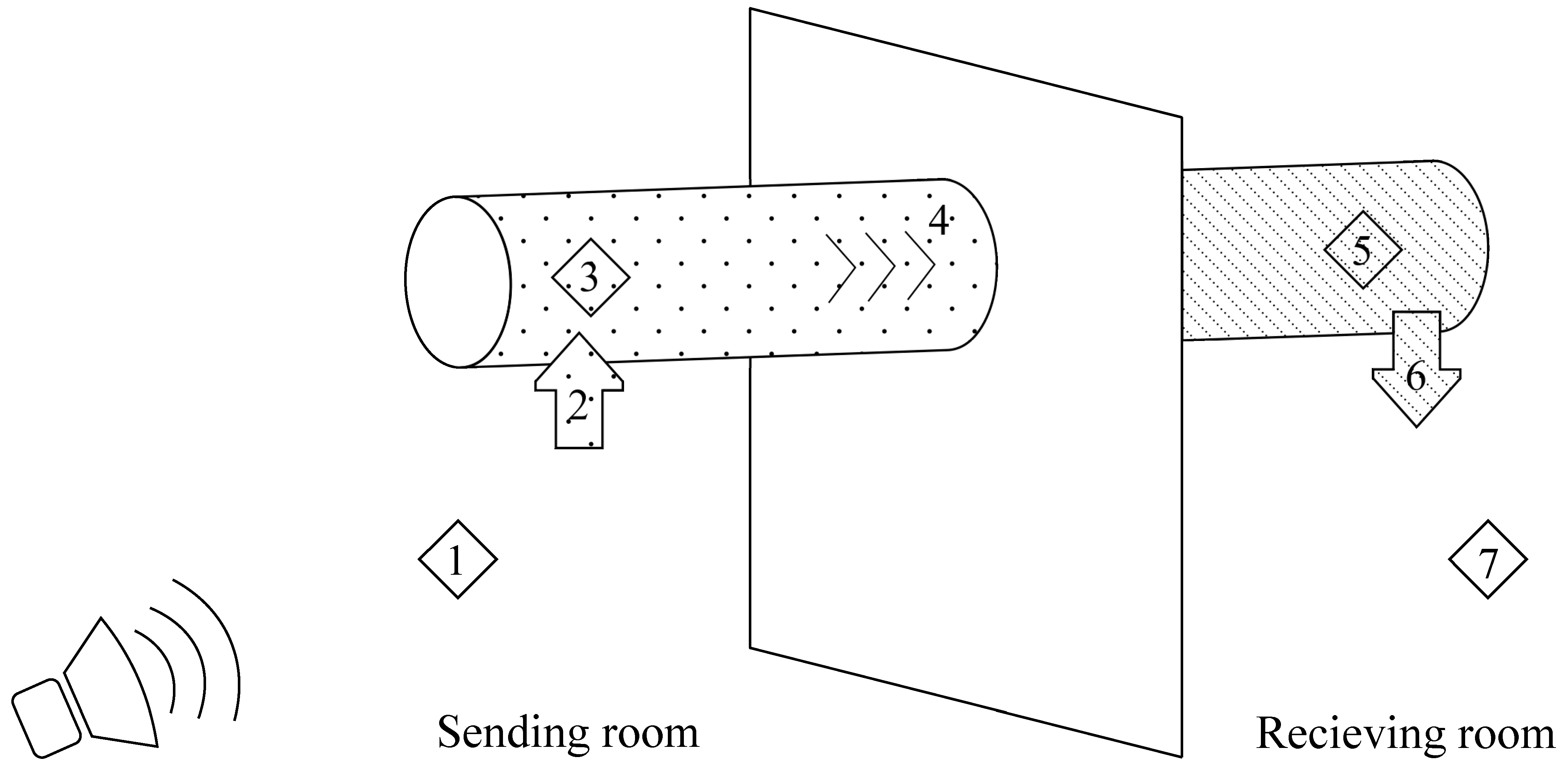
1] investigates how the surface area of a ventilation duct affects sound reduction and presents theoretical models to calculate the combined sound reduction index of a duct wall. The initial model was based on Figure 1, which presents how the sound travels from the sending room to the receiving room if only the surface area affects the sound transmission. Elements 1 and 7 in Figure 1 describe the sound power in the different rooms and Elements 3 and 5 describe the sound power inside the ventilation duct. Elements 2 and 6 indicate the sound transmission loss of breakin and breakout between the sending and receiving room along the surface area of the ventilation duct, marked with different patterns. Lastly, Element 4 is the sound attenuation inside the ventilation duct and the damping of sound increases with the length of the ventilation duct. The model in Figure 1 could occur in the field when a ventilation duct passes by a room without any air diffuser.
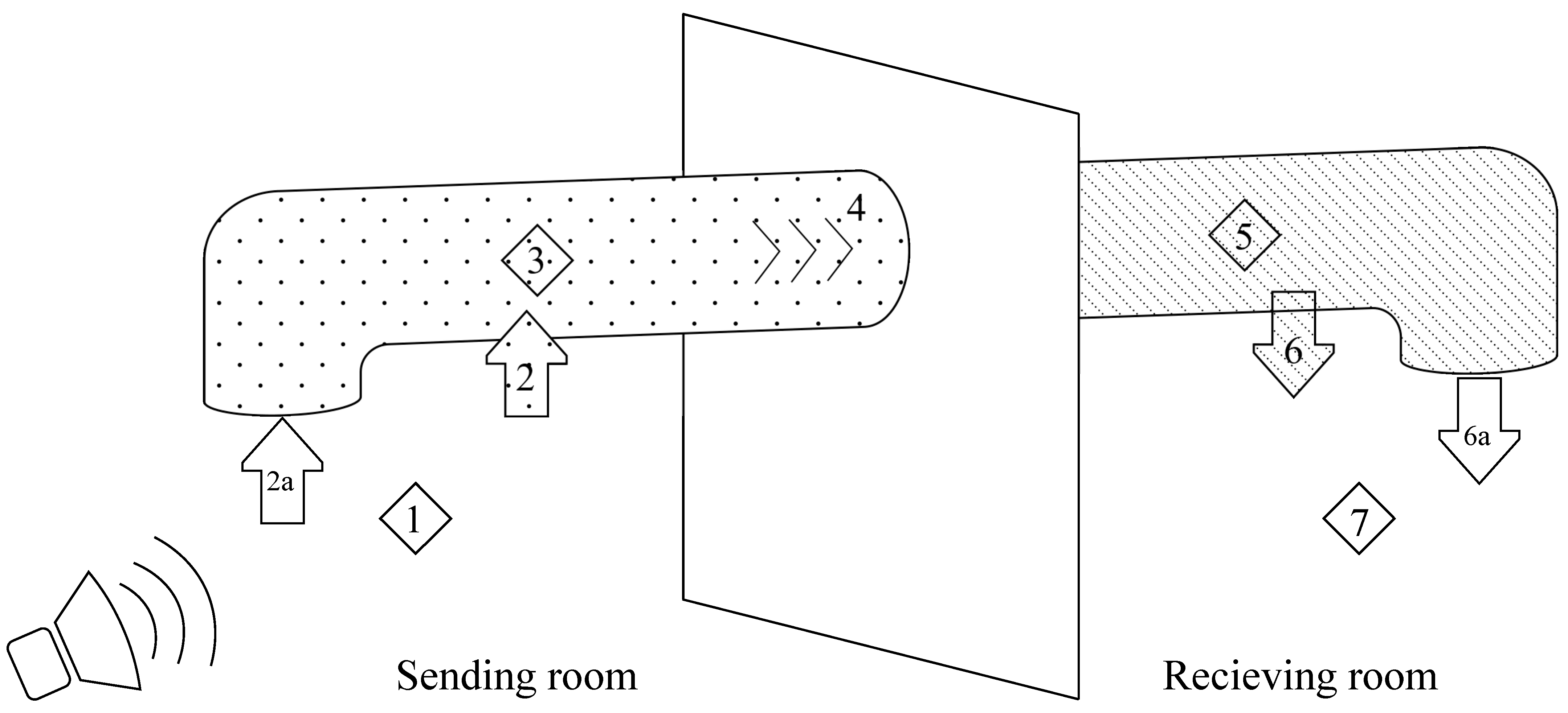
Scenarios that include air diffusers can be illustrated according to Figure 2 where air diffusers can be on one or two sides of the wall. The model in Figure 2 has two more paths included, which are denoted as Elements 2a and 6a. They describe the sound transmission loss of break-in and breakout via the air diffusers. The path from Element 2a to 6a can be described by the term crosstalk.
The use of internal lining affects path number 4 and therefore improves the scenarios described in Figure 1 and Figure 2. The use of external lagging only affects break-in and breakout through the surface area described as Elements 2 and 6 in Figure 2.
The use of a silencer affects different paths depending on the placement, which is illustrated in Figure 3. If the silencer is placed in position a marked as blue, it primarily affects Element 2a. Sound is still able to break-in at the remaining path between the silencer and the wall. However, if the silencer is placed in position b marked as green, Elements 2, 2a and 4 are affected. Therefore, the placement of a silencer can be critical depending on the problem that needs to be solved. A ceiling between the sending room and the ventilation duct primarily affects Element 2 since the air diffusers (placed at Elements 2a and 6a) usually goes through the ceiling.
The placement of silencers, related to Figure 3, can be adapted to external lagging using similar principles. If external lagging is placed on a limited surface of the ventilation duct in position b, sound will break into the ventilation duct longer away from the wall, which is more advantageous compared to position a.
Ventilation ducts have a few acoustical properties that theoretical models in general should consider. Both rectangular and circular ventilation ducts have different acoustic cross modes, and the cut-off frequency is the lowest of these modes [36], described in Equations (1) and (2) [17]. Sound transmission loss of break-in and breakout for circular ventilation ducts is also dependent on the ring frequency presented in Equation (3) [37,38]. The ring frequency can be described as the frequency where an equivalent circular ring exhibits axisymmetric free vibrations [39]. The sound transmission loss for rectangular ducts is divided into other areas with a different frequency, called the longitudinal or cross-over frequency presented in [36,40], and seen in Equation (4). Plane mode transmission dominates below the cross-over frequency and multi-mode transmission dominates above [36]. The calculated values are presented in Table A2 (Appendix B).
f 1 , circular = 0.586 · c 0 d
f 1 , rectangular = 0.5 · c 0 a
f R = c L P
f L = 613 a · b .
The cut-off frequency in Equations (1) and (2) is dependent on the speed of sound in air, c 0 , and the diameter of the circular duct, d , or the longest dimension of the rectangular duct, a . The ring frequency in Equation (3) is determined by the speed of sound of the ventilation duct material, c L , and the perimeter of the circular duct, P . The longitudinal or cross-over frequency in Equation (4) is dependent on the longest and shortest dimension of the rectangular duct, a and b .
A system with a wall, a ventilation duct and external lagging with different lengths can be described with a combined sound reduction according to Equation (5):
R combined = 10 · log 10 ( S wall + M duct + M wrap S wall · 10 R wall 10 + M wrap · 10 ( R wrap + R duct ) 10 + M duct · 10 R duct 10 ) .

3. Method

The experimental part was performed according to [
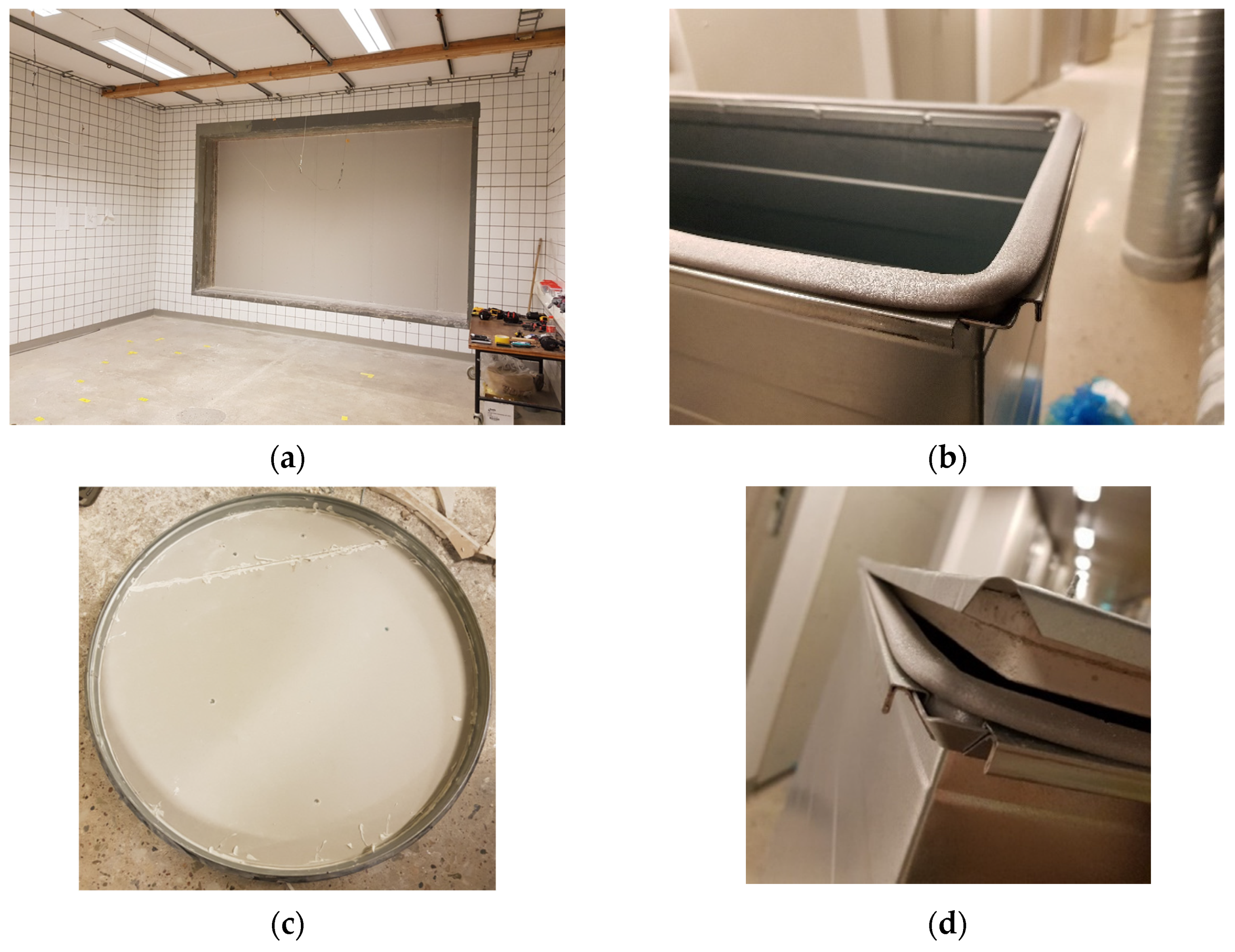
2] and took place in the sound transmission laboratory at Lund University, LTH, Faculty of Engineering, Division of Acoustics. The laboratory consists of two horizontal rooms, separated by a heavy wall with an opening where a 10 m2 mock-up wall can be constructed (Figure 4a). The experimental part in [2] tested three different types of walls. Lab measurements yielded R w of 35, 46, and 54 dB according to ISO 717-1:2013 [41] and S T C of 35, 46, and 53 dB according to ASTM E413-16 [42]. The edges, between the mock-up wall and the heavy wall, were covered with sealant on all sides.
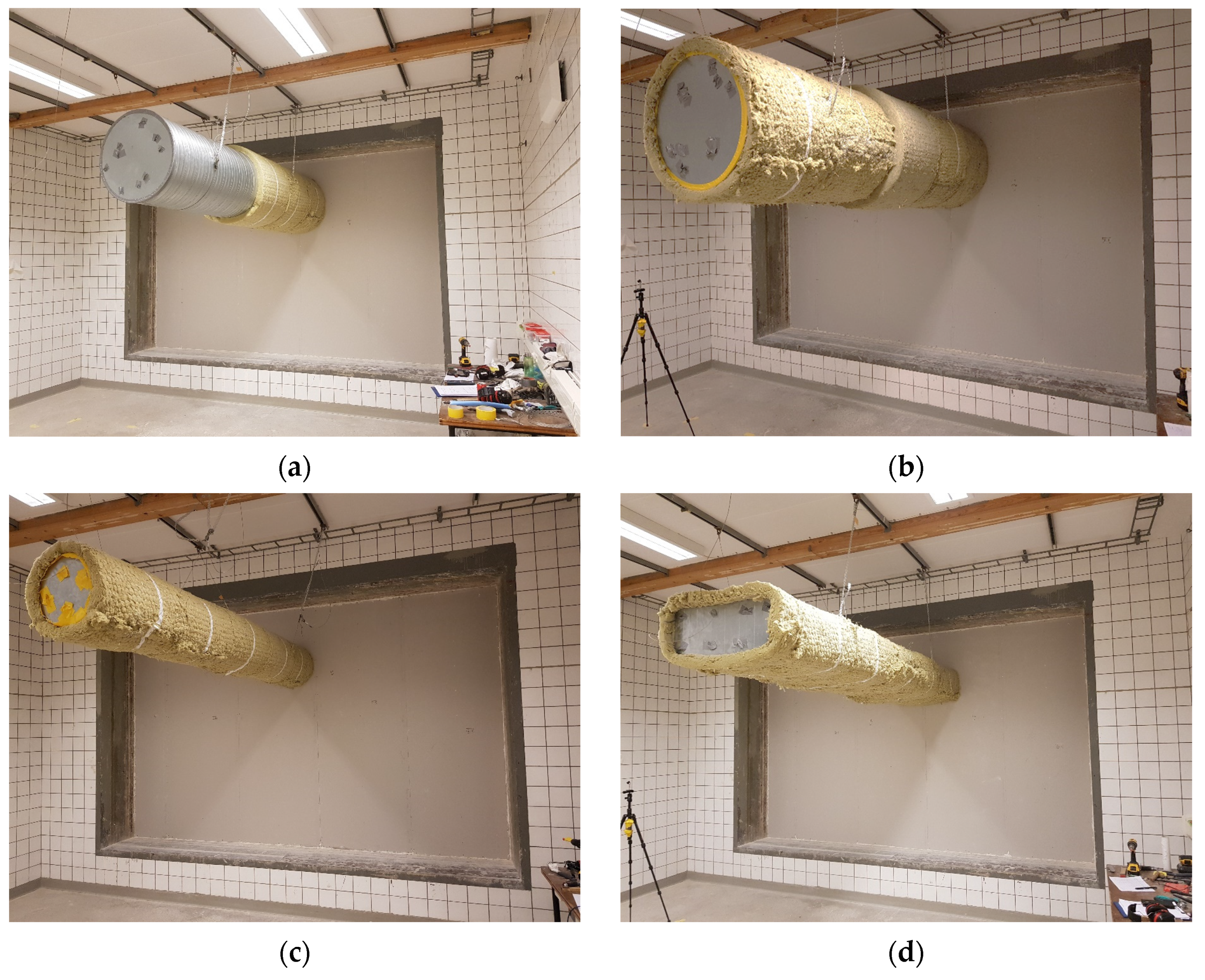
Two circular and one rectangular ventilation ducts were used together with the three different walls in [2]. The dimensions of the ventilation ducts were Ø315 and Ø630 mm for the circular duct and 700 × 250 mm for the rectangular duct. Both ends of the ventilation duct were plugged with a metal plate, with two gypsum boards and sealant on the inside of the plates (see Figure 4c,d), since the main objective was to measure how the surface area affects the sound transmission. The connection was made airtight between the metal plate and the ducts with a rubber or foam lining (Figure 4b) on the metal plates.
The impact of the ventilation ducts on the test walls was quantified by measuring the walls without any holes, as shown in Figure 4a. The measurements with no holes represent reference values, R wall , that are used in Equation (5). Different treatments were applied on the duct and the main treatments are presented below. Treatments are only applied if the measured combined sound reduction index with duct and wall is below the reference wall. A sealant was applied between the ventilation duct and the wall for all cases below. More information about the measurements can be obtained in [1,2].
  • External lagging with 50 mm stone wool, density of 100 kg/m3, closest to the wall with a length of 600 mm.
  • External lagging with 50 mm stone wool, density of 100 kg/m3, closest to the wall with a length of 1200 mm.
  • External lagging with 50 mm stone wool, density of 100 kg/m3, closest to the wall with a length of 1800 mm.
  • External lagging with 50 mm stone wool, density of 100 kg/m3, along the whole duct.
  • External lagging with 100 mm stone wool, density of 100 kg/m3, closest to the wall with a length of 1800 mm. The rest of the duct is covered with 50 mm stone wool, density of 100 kg/m3.
The different walls are further on described as the following types, measured in the laboratory according to [2].
  • Wall A. Sound reduction index: R w = 35   dB or sound transmission class: S T C = 35   dB
  • Wall B. Sound reduction index: R w = 46   dB or sound transmission class: S T C = 46   dB
  • Wall C. Sound reduction index: R w = 54   dB or sound transmission class: S T C = 53   dB
Pictures from the measurements in [2] are displayed in Figure 5; different treatments with external lagging (external sound insulation) are applied on different ventilation ducts according to cases 1–5 above.

4. Theoretical Models with External Lagging

The improvement of external lagging with stone wool according to different cases presented under Section 3 can be expressed with developed theoretical models. The models are based on measurements from [2] and previous theoretical models from [1], which describes the sound reduction of the ventilation duct. The models are developed with an analytical approach. For circular ducts, the equations are divided into different frequency areas depending on the cut-off frequency, f 1 , and the ring-frequency, f R . For rectangular ducts, the equations are instead divided into frequency areas depending on the cut-off frequency, f 1 , and the longitudinal (or cross-over) frequency, f L . Units for different variables are presented in Table A1 (Appendix B). Calculated values for frequencies presented in Equations (1)–(4) are displayed in Table A2.

4.1. Theoretical Models with External Lagging for Circular Ducts

In the development of theoretical models for circular ducts, the wrapping length closest to the wall proved to be the most important parameter when the ventilation duct was partially covered with external lagging. Equation (5) was therefore modified to consider this in Equation (6) below. It is important to note that R wrap only describes the addition of sound reduction caused by the external lagging and that R duct needs to be included to the total sound reduction described in Equation (6):
R c i r c , c o m b i n e d = 10 · log 10 ( S wall + M duct + M wrap S wall · 10 R wall 10 + M wrap · 10 ( R wrap + R duct ) 10 + ( L L wrap L ) 4 · M duct · 10 R duct 10 ) .
When the ventilation duct is completely covered with external lagging, L wrap = L , one term disappears automatically from the equation above. R wrap can be calculated with the equations below, R duct can be calculated using Ref. [1] and R wall can be obtained from the manufacturers (laboratory measurements), by calculations with a building acoustic software, or by calculations with equations from the literature.
Ref. [1] introduces a new equation that specifies another frequency area that is dependent on the cut-off frequency for circular ducts, presented in Equation (7). The calculated values are presented in Table A2 (Appendix B).
f e = f 1 , circular 1.9 .

4.1.1. Theoretical Models When Circular Ventilation Ducts Are Partly Wrapped

A theoretical model is developed when a circular ventilation duct is partly covered with external lagging and the sound reduction, depending on frequency, is divided into four main zones according to Equations (8)–(13), which together describe R wrap .
When f f e
R c i r c , p a r t l y , 1 = 10 · log 10 ( q wrap 0.7 2 · S · π · ( S + 1.9 · max ( f e f ,   100 ) 0.8 / d f 1 , circular ) )
where S is the cross-section area of the ventilation duct and q wrap is the mass per unit area of the external lagging.
When f e < f f 1 , circular
R c i r c , p a r t l y , 2 = 10 · log 10 ( q wrap · f S · c 0 · π 2 ) .
When f 1 , circular < f < f R
R c i r c ,   p a r t l y , 3 = 10 · log 10 ( max ( f f 1 , circular ,   100 ) · q wrap 3 · 2.2 ( L L wrap L ) P 2 · π 2 · f 1 , circular 0.3 )
where L is the total length of the ventilation duct and L wrap is the length of the external lagging. The ring frequency does not only cause a drop in sound reduction at the nearest one third octave band, denoted as f R , r o u n d e d , but also at the one third octave band below that, denoted as f R , r o u n d e d 1 / 3 .
When f f R , r o u n d e d 1 / 3
Substract   R c i r c , p a r t l y , 3   with :   P · ( L L wrap ) .
When f f R , r o u n d e d
Substract   R c i r c , p a r t l y , 3   with :   2 · P · ( L L wrap ) .
When f > f R
R c i r c , p a r t l y , 4 = 10 · log 10 ( f 0.1 · q wrap ) .

4.1.2. Theoretical Models When Circular Ventilation Ducts Are Completely Wrapped

The sound reduction index increases significantly when the whole circular ventilation duct is covered with external lagging according to Equations (14)–(17), which together describe R wrap . Ref. [2] presents the basic equations to estimate the sound reduction, which are further developed in this article.
When f f e
R c i r c , f u l l , 1 = 10 · log 10 ( q wrap 2 2 · S · π · ( S + 1.9 · max ( f e f ,   100 ) 0.8 / d f 1 , circular ) ) .
When f e < f f 1 , circular
R c i r c , f u l l , 2 = 10 · log 10 ( q wrap 2.7 · f S · c 0 1.4 · π 2 · P 2 ) .
When f 1 , circular < f < f R
R c i r c , f u l l , 3 = 10 · log 10 ( max ( f f 1 , circular ,   40 · q wrap P 2 ) 2 · q wrap 2 P 2 · π 2 · f 1 , circular ) .
When f > f R
R c i r c , f u l l , 4 = 10 · log 10 ( f · q wrap ) .

4.2. Theoretical Models with External Lagging for Rectangular Ducts

Similar to circular ducts, in the development of theoretical models for rectangular ducts, the wrapping length closest to the wall proved to be the most important parameter when the ventilation duct was partially covered with external lagging. Equation (5) was therefore adjusted to form Equation (18) with the same principles made for Equation (6). The combined sound reduction index of the wall, the rectangular ventilation duct, and external lagging as acoustical treatment can be described according to Equation (18). As mentioned before, note that R wrap only describes the addition of the sound reduction caused by the external lagging and that R duct needs to be included to the total sound reduction caused by that path described in Equation (18).
R r e c t , c o m b i n e d = 10 · log 10 ( S wall + M duct + M wrap S wall · 10 R wall 10 + M wrap · 10 ( R wrap + R duct ) 10 + ( L L wrap L ) 2 · M duct · 10 R duct 10 ) .
R wrap can be calculated with equations below, R duct can be calculated using Ref. [1] and R wall can be obtained from the manufacturers (laboratory measurements), by calculations with a building acoustic software, or by calculations with equations from the literature.

4.2.1. Theoretical Models When Rectangular Ventilation Ducts Are Partly Wrapped

A theoretical model is developed when a rectangular ventilation duct is partly covered with external lagging (wrapped) and the sound reduction depending on frequency is divided into three main zones according to Equations (19)–(21), which together describe R wrap .
When f f 1 , rectangular
R r e c t , p a r t l y , 1 = 10 · log 10 ( q w r a p 1.5 · ( 0.5 + L wrap L ) 1.2 · f 1 , rectangular 0.7 f · S · π 2 ) .
When f 1 ,   rectangular < f f L
R r e c t , p a r t l y , 2 = 10 · log 10 ( max ( f f 1 , rectangular ,   10 · L wrap L ) 0.2 · q wrap 3 P · π 2 · f 1 , rectangular 0.2 ) .
When f > f L
R r e c t , p a r t l y , 3 = 10 · log 10 ( f · q wrap ) .

4.2.2. Theoretical Models When Rectangular Ventilation Ducts Are Completely Wrapped

Similar to circular ducts, the sound reduction increases significantly when the whole rectangular ventilation duct is covered with external lagging (wrapped) according to Equations (22)–(24), which together describe R wrap . Ref. [2] presents the basic equations to estimate the sound reduction, which are further developed in this article.
When f f 1 , rectangular
R r e c t , f u l l , 1 = 10 · log 10 ( q wrap 2.1 10 · S · π ) .
When f 1 , rectangular < f f L
R r e c t , f u l l , 2 = 10 · log 10 ( max ( f f 1 , rectangular , 50 ) 1.8 · q wrap 3 P · π 2 · f 1 , rectangular 1.4 ) .
When f > f L
R r e c t , f u l l , 3 = 10 · log 10 ( f · q wrap ) .

5. Results

5.1. Measurement Results Compared to the Developed Theoretical Models

The sound reduction for the three different ventilation ducts with different lengths of external lagging combined with the sound reduction of the walls can be calculated according to equations in Section 4.1 and Section 4.2. The developed models are based on an analytical approach.
Measurement results compared to the developed theories are presented in Figure 6, Figure 7 and Figure 8 for Wall C with the highest sound reduction index of R w = 54   dB and sound transmission class of S T C = 53   dB . The calculations, compared to measurements for Walls A and B with lower sound reduction indices and sound transmission classes, are displayed in Figure A1, Figure A2, Figure A3, Figure A4 and Figure A5 (Appendix A) described under Section 3.

5.2. Suspended Absorbent Ceilings: Estimated Calculations

Suspended ceilings have a positive effect on the sound reduction when a ventilation duct passes through a wall. The sound reduction for an absorbent ceiling can be estimated based on sound pressure insulation values, D p r , from different products measured according to ISO 11546-1 [43]. The values measured according to Ref. [43] are expressed for one ceiling and the model in Figure 1 could include one suspended ceiling in each room. The total sound reduction addition can be estimated and added in Equation (5) instead of R wrap .
Laboratory measurements with sound pressure insulation values, D p r , have been obtained for two different types of ceilings. The first one, called Ceiling A, is built up with 40 mm absorbent tiles. The second, called Ceiling B, is built up with a gypsum board behind 40 mm absorbent tiles. Ceiling B will therefore have higher sound insulation compared to Ceiling A.
Estimated calculations are presented in Figure 9 and Figure 10 with Ceiling A and B together with Wall C and the three different ventilation ducts investigated in this paper. The calculations assume that suspended absorbent ceilings are mounted in both rooms, with a model based on Figure 1, and that the total sound pressure insulation is almost twice the sound pressure insulation of one ceiling. The calculations could therefore be overestimating the sound reduction, meaning that the positive effect of suspended ceilings presented in Figure 9 and Figure 10 are lower than presented. Calculations for Wall B are presented in Figure A6 and Figure A7 (Appendix A). Calculations for Wall A are not presented since the difference in sound reduction is minor between the reference wall and when an untreated ventilation duct passes through. Similar results and conclusions can be expected for Wall A as for Wall B.

6. Discussion

The agreement between measurements from [2] and new developed theoretical models in [1], combined with the models under Section 4.1 and Section 4.2, is sufficient with few minor deviations for certain frequency bands. However, some consideration needs to be taken around and below the frequency named f e since the difference is very small between the reference wall and when a ventilation duct passes through the wall without treatments. Further studies are therefore required with a wall that has higher performance in a low frequency to model the combined sound reduction index around and below f e . Nonetheless, the developed theory in this study models different wrapping lengths with high accuracy. The uncertainties of the models are the duct length since the length was constant, and the shape of rectangular ducts since only one rectangular duct was tested.
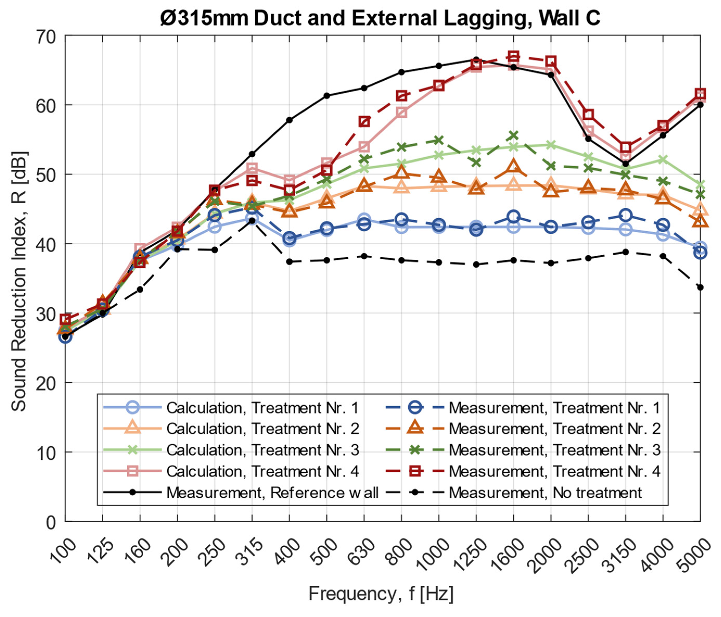
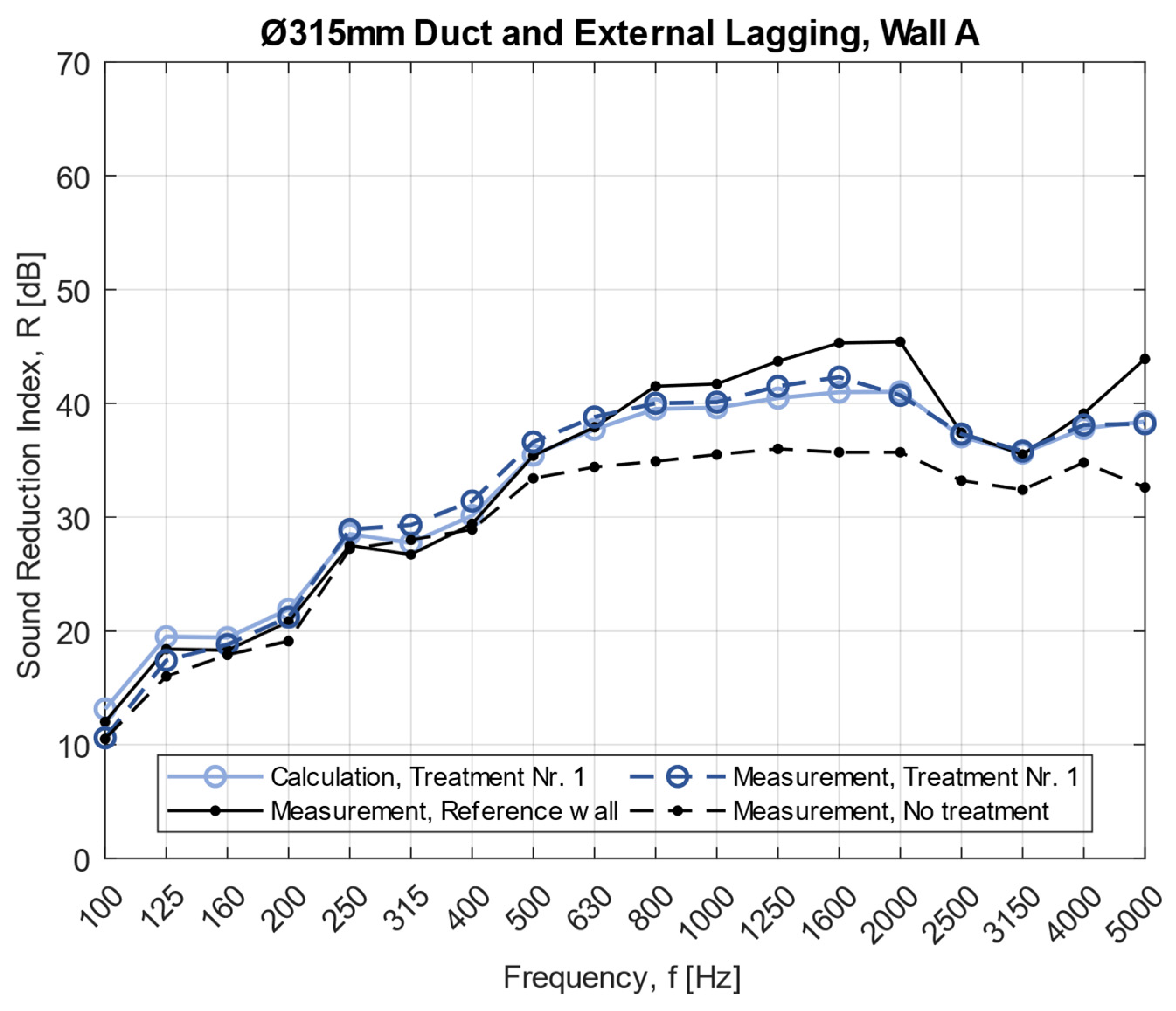
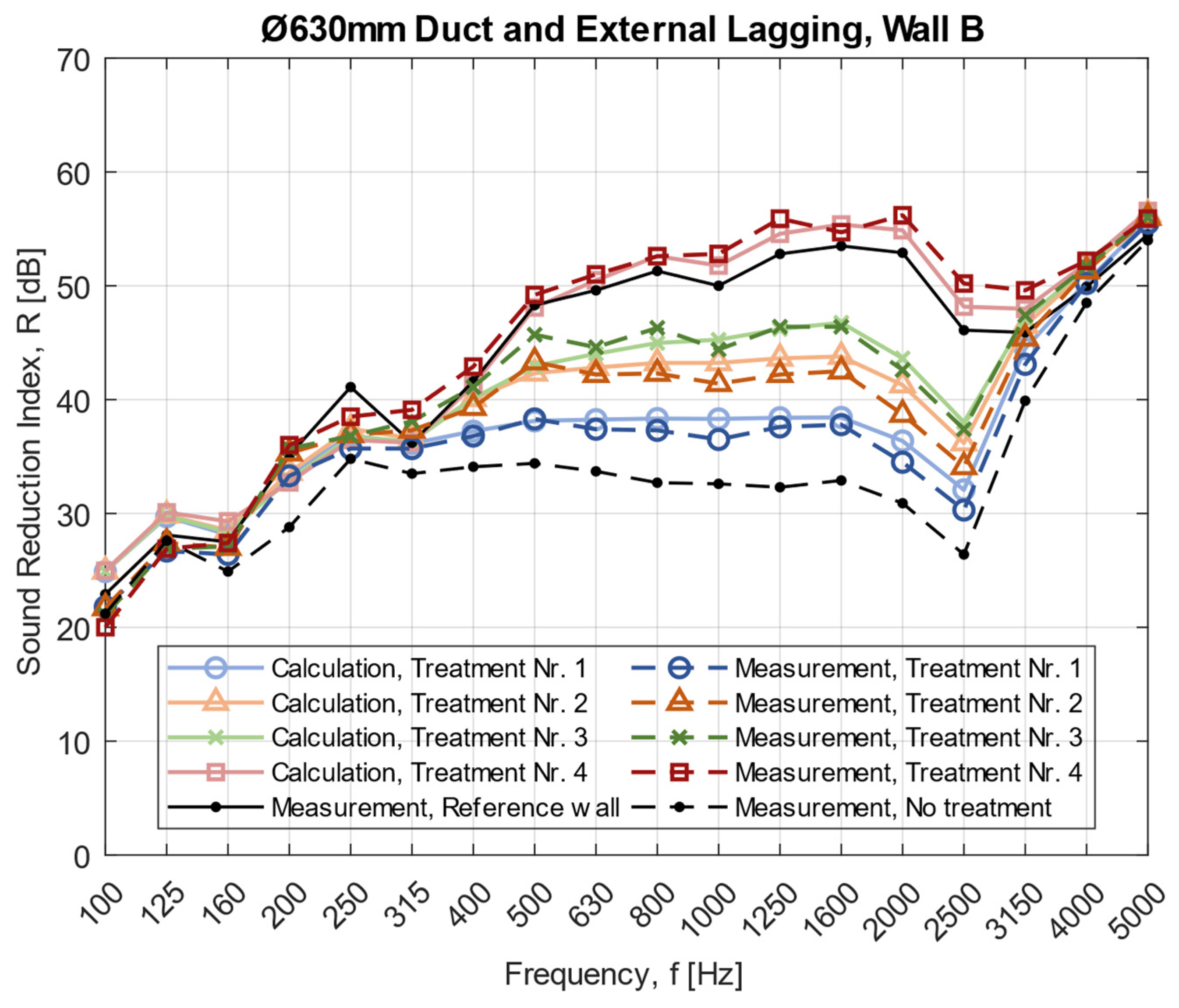
The frequency range between f 1 and f R   /   f L 
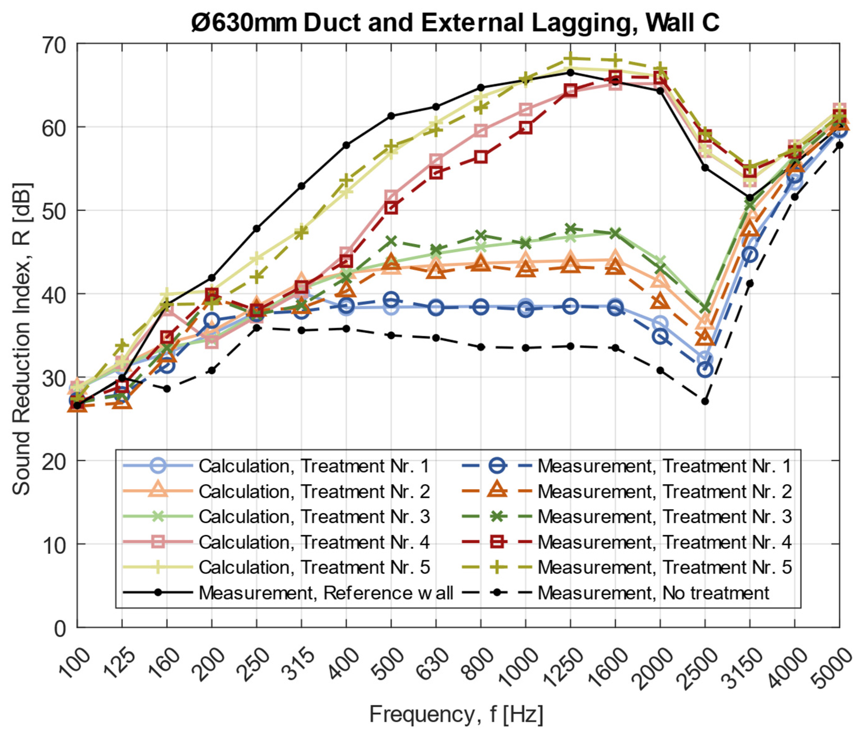
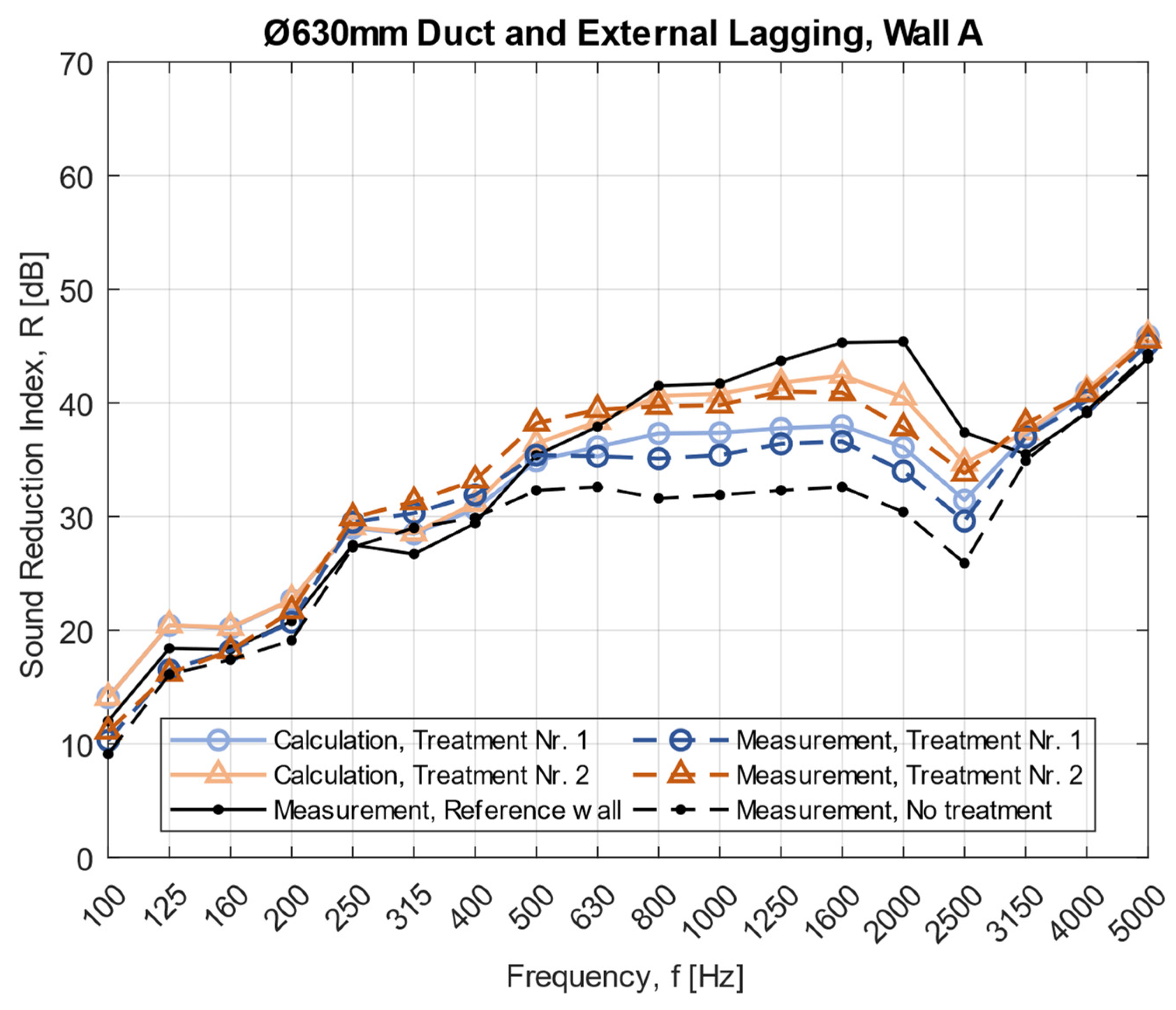
(circular or rectangular duct) is most affected when external lagging with stone wool is applied as an acoustical treatment on the ventilation ducts. The difference is very large if the ventilation duct is covered with external lagging along parts of its surface area or if the whole ventilation duct is covered. When the ventilation duct with a diameter of 630 mm is covered with 50 mm stone wool at a length of 1800 mm (Treatment 3), the sound reduction increases at the ring frequency ( f R , 630 = 2554   Hz   2500   Hz ) with 11 dB compared to no treatments (see Figure 7). However, when the rest of the duct is covered (length of 1200 mm), the increase is in total 32 dB, meaning that the extra 1200 mm yields an improvement of 21 dB. The improvement is clearest for the larger circular ventilation duct, but similar improvements are visible for the smaller circular duct in 
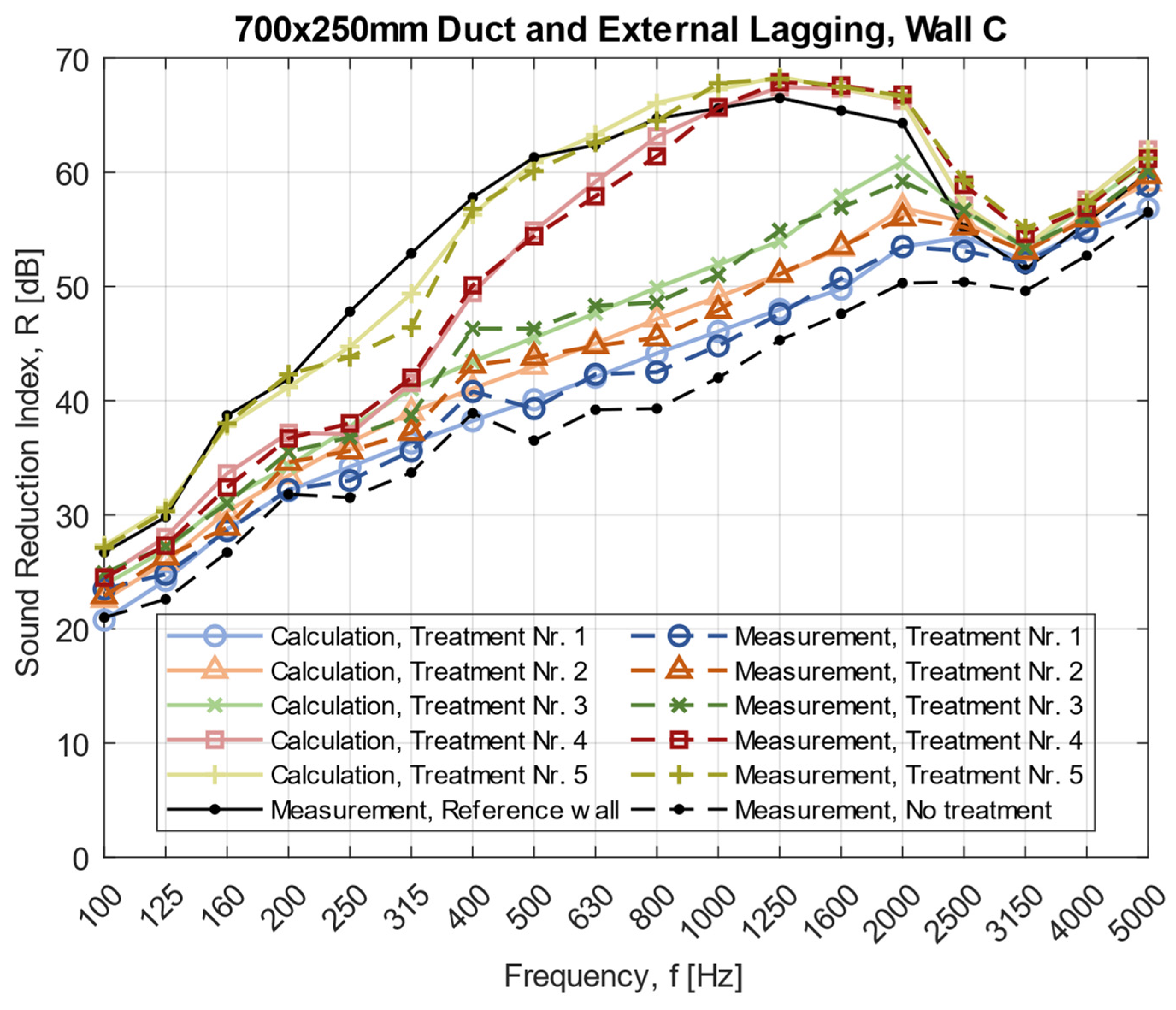
Figure 6. Furthermore, for the rectangular ventilation duct and treatment 3, the sound reduction increases around the cross-over frequency ( f L , 700 = 1465   Hz   1600   Hz ) with 9 dB compared to no treatments (see Figure 8). Moreover, when the rest of the rectangular ventilation duct is covered (length of 1200 mm), the increase is in total 20 dB, meaning that the extra 1200 mm yields an improvement of 11 dB.
Measurements and the developed models consider the fact that the area of the ventilation duct closest to the wall has the greatest positive effect on the combined sound reduction index. Similar principles can be adapted to the placement of silencers, meaning that a silencer has the best effect on the sound transmission and attenuation if it is placed directly against the wall.
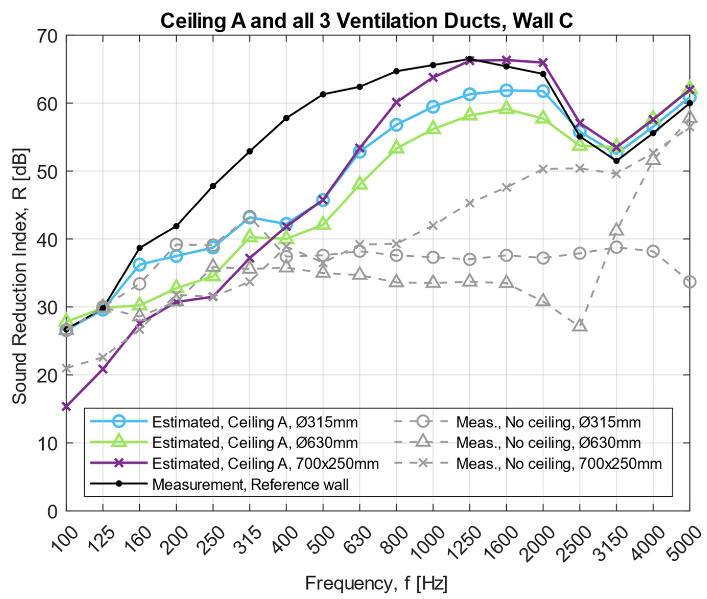
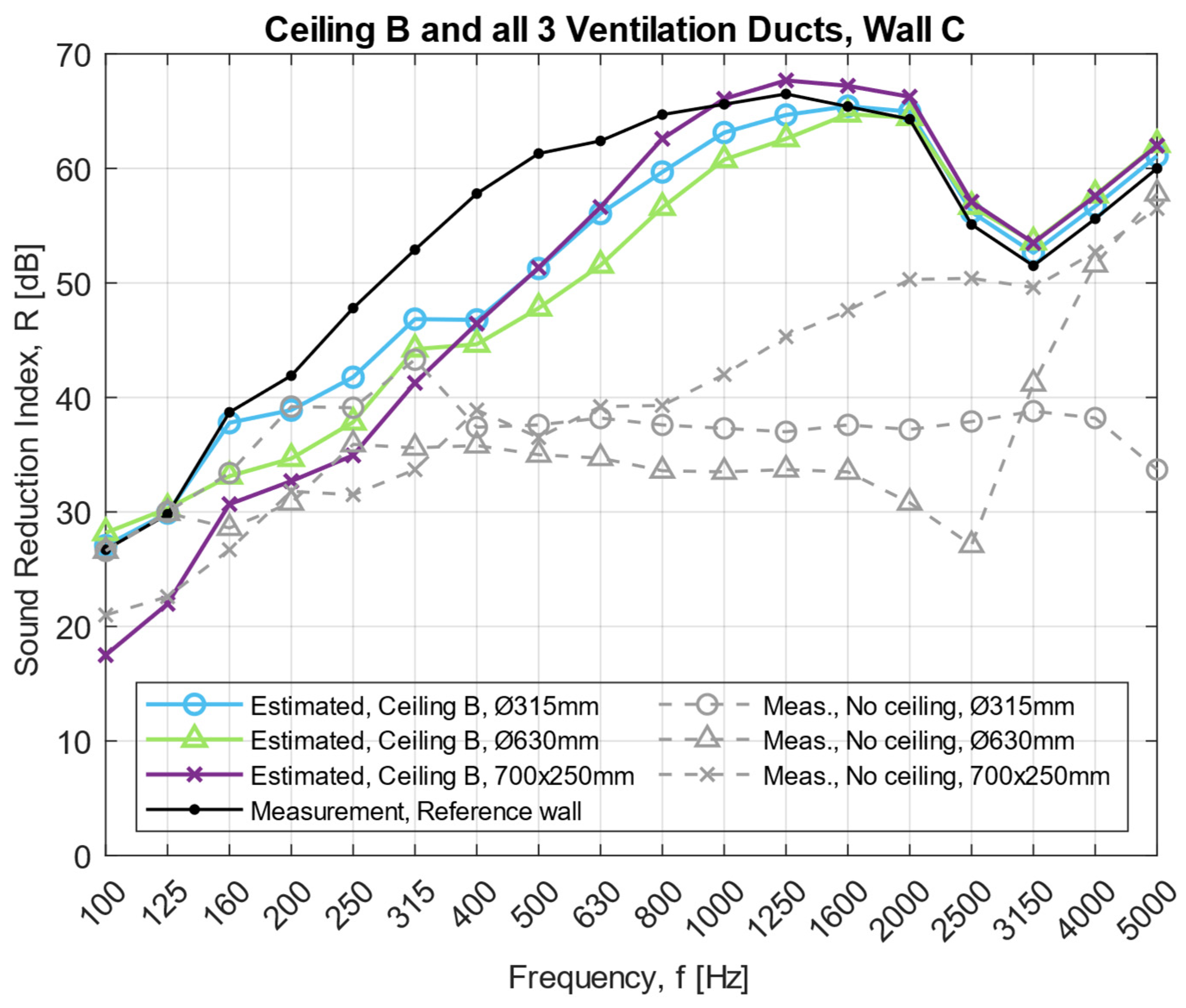
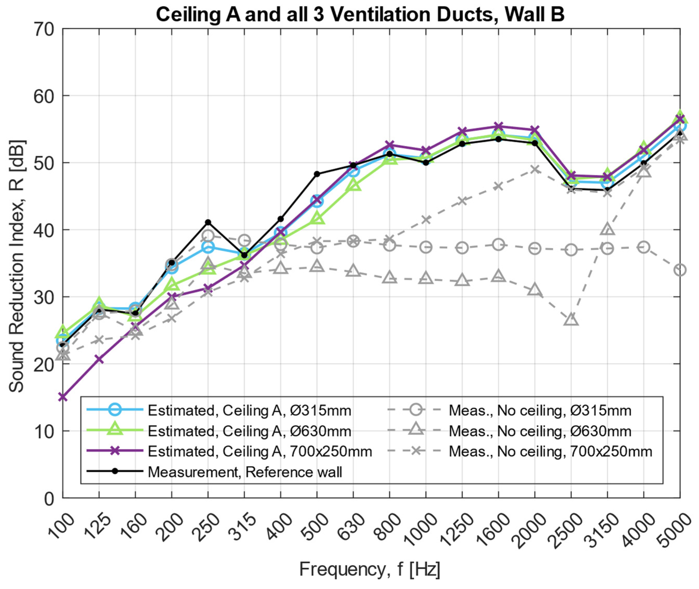
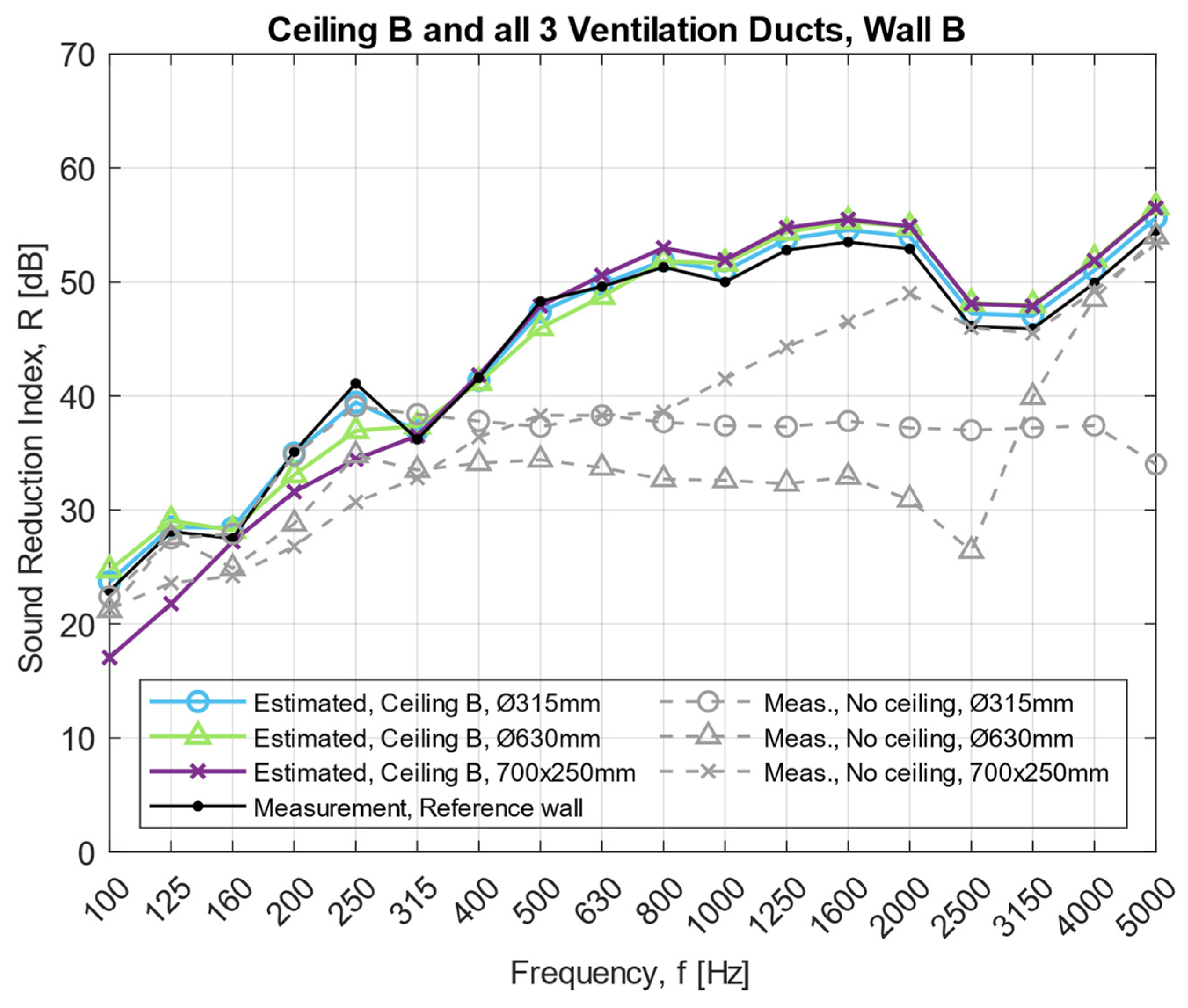
Measurements indicate that external lagging with stone wool can be used as an effective acoustical treatment for both small and large ventilation ducts combined with walls of both low and high sound reduction indices. However, other treatments may be more effective to use in some scenarios. Moreover, suspended ceilings are often used in buildings, which will improve the sound insulation to some extent. Depending on the choice of suspended ceiling, fewer treatments may be required if a ventilation duct passes through a wall above the suspended ceiling. Estimated calculations of suspended ceilings with absorbent tiles show that they can work as a main acoustical treatment for large ventilation ducts through walls with a sound reduction up to R w = 46 dB, see Figure A6 and Figure A7 (Appendix A). However, they are not sufficient for walls with R w = 54 dB even if the suspended ceiling is built up with a 40 mm absorber and a gypsum board (see Figure 9 and Figure 10). More treatments are thereby required in addition to a suspended ceiling for walls with higher sound reduction indices. The calculations presented in Figure 9, Figure 10, Figure A6 and Figure A7 could be overestimated, meaning that the sound reduction might be lower. Therefore, consideration needs to be taken when analyzing these results, specifically when a large ventilation duct passes through walls with a sound reduction of around R w = 46 dB.
It should be noted that a ceiling with gypsum boards will acquire a high sound insulation and in some cases be enough as an acoustic treatment for the model presented in Figure 1. However, the problems with larger ventilation ducts often occur in schools, offices, and hospitals and the room acoustic requirements need to be considered. Therefore, it might not be possible to have a ceiling with gypsum boards because the sound absorption will not be sufficient. In addition to a suspended ceiling with absorption, other treatments may be necessary to fulfil the requirements.
One effective solution, in addition to suspended ceilings, is to connect a silencer to the ventilation duct system. However, the sound attenuation of a silencer decreases with the diameter of the ventilation duct based on various technical data sheets from suppliers. Some suppliers offer silencers with a divider in the centre, called a baffle, which helps to improve the surface damping area of the silencer, but it might not be enough for larger ventilation ducts.
Crosstalk in ventilation duct systems describes when the sound travels via air diffusers between rooms, displayed by Elements 2a and 6a in Figure 2. External lagging is, for this scenario, not helpful as an acoustic treatment because it only affects break-in and breakout of the ventilation duct, described as Element 2 and 6 in Figure 2. When both the sound reduction due to flanking and crosstalk needs to be solved, a silencer might be the optimal solution since silencers are an effective way of solving both the sound attenuation and the sound transmission between two rooms connected with a ventilation duct.
It is important for designers to consider the scenarios displayed in Figure 1 and Figure 2 to find an optimal solution when choosing acoustical treatments and further studies are required when different acoustical treatments are combined to produce a design scheme.

7. Conclusions

The purpose of this article was to investigate different acoustical treatments and develop theoretical models when external lagging is used on parts or on the whole ventilation duct to reduce flanking sound transmission.
The number of acoustical treatments required depends on several factors, including the dimensions and shape of the ventilation duct, the sound reduction of the wall and the connection between the duct and the wall. Moreover, the number of treatments will also depend on whether there are air diffusers connected to the ventilation ducts to supply the different rooms with air.
Theoretical models are developed for external lagging (wrapping with stone wool) on ventilation ducts as an acoustic treatment through walls. The models take the wrapping length into consideration and measurement data agrees with the developed theory with few deviations for certain frequency bands. The models clarify that the distance closest to the wall has the main impact on the sound reduction for the combined system.
Suspended ceilings with a 40 mm absorber could be enough as an acoustical treatment to prevent the sound from propagating via the surface area of the ventilation duct when it passes through walls of lower sound reduction indices of around R w = 35 dB or sound transmission classes around S T C = 35 dB. Furthermore, suspended ceilings with a 40 mm absorber and a gypsum board behind could be enough for walls with R w and S T C up to 46 dB.
The whole system, including wall, ventilation duct, air diffusers, and suspended ceiling, must be investigated when acoustical treatments are proposed. This article mainly investigated how the surface area of ventilation ducts and suspended ceilings affect the sound transmission. Sometimes, other treatments instead of external lagging may be more effective, such as the use of silencers, and in some cases, the suspended ceiling could be enough. However, external lagging seems to be the only effective solution in offices and schools when a large ventilation duct passes through a wall with high sound reduction.

Author Contributions

Writing—Original Draft Preparation: E.N.; Formal Analysis: E.N.; Methodology: E.N.; Writing—Review and Editing: E.N.; Review and Supervision: S.M., D.B.H. and N.-G.V. All authors have read and agreed to the published version of the manuscript.

Funding

This research received no external funding.

Institutional Review Board Statement

Not applicable.

Informed Consent Statement

Not applicable.

Conflicts of Interest

The authors declare no conflict of interest.

Appendix A

Figure A1. Theoretical models compared to measurements with external lagging as acoustic treatment. Ventilation duct with Ø315 mm through wall A with a sound reduction index of R w = 35 dB. External lagging is mounted at a partial length of 0.6 m (Treatment 1) with 50 mm stone wool, density of 100 kg/m3, closest to the wall.
Acoustics 04 00017 g0a1
Figure A2. Theoretical models compared to measurements with external lagging as acoustic treatment. Ventilation duct with Ø315 mm through wall B with a sound reduction index of R w = 46 dB. External lagging is mounted at partial lengths of 0.6–1.2 m (Treatment 1 and 2) with 50 mm stone wool, density of 100 kg/m3, closest to the wall.
Acoustics 04 00017 g0a2
Figure A3. Theoretical models compared to measurements with external lagging as acoustic treatment. Ventilation duct with Ø315 mm through wall A with a sound reduction index of R w = 35 dB. External lagging is mounted at partial lengths of 0.6–1.2 m (Treatment 1 and 2) with 50 mm stone wool, density of 100 kg/m3, closest to the wall.
Acoustics 04 00017 g0a3
Figure A4. Theoretical models compared to measurements with external lagging as acoustic treatment. Ventilation duct with Ø315 mm through wall B with a sound reduction index of R w = 46 dB. External lagging is mounted at partial lengths of 0.6–1.8 m (Treatment 1–3) and full length (Treatment 4) with 50 mm stone wool, density of 100 kg/m3, closest to the wall.
Acoustics 04 00017 g0a4
Figure A5. Theoretical models compared to measurements with external lagging as acoustic treatment. Ventilation duct with dimension: 700 × 250 mm through wall B with a sound reduction index of R w = 46 dB. External lagging is mounted at partial lengths of 0.6–1.8 m (Treatment 1–3) with 50 mm stone wool, density of 100 kg/m3, closest to the wall.
Acoustics 04 00017 g0a5
Figure A6. Estimated theory with suspended absorbent ceiling, Ceiling A, as acoustical treatment. Ventilation duct with dimensions of: Ø315, Ø630 and 700 × 250 mm through wall B with a sound reduction index of R w = 46 dB.
Acoustics 04 00017 g0a6
Figure A7. Estimated theory with suspended absorbent ceiling, Ceiling B, as acoustical treatment. Ventilation duct with dimensions of: Ø315, Ø630 and 700 × 250 mm through wall B with a sound reduction index of R w = 46 dB.
Acoustics 04 00017 g0a7

Appendix B

Table A1. Units for different variables.
VariableUnit, SI
am
bm
c0, cLm/s
dm
Lm
Mduct, Mwallm2
Pm
qwrapkg/m2
S, Swallm2
Table A2. Calculated frequency values depending on the size and shape of the ventilation duct.
VariableValue:
f 1 , 315 638 Hz
f 1 , 630 319 Hz
f 1 , 700 245 Hz
f e , 315 336 Hz
f e , 630 168 Hz
f R , 315 5108 Hz
f R , 630 2554 Hz
f L , 700 1465 Hz

References

  1. Nilsson, E.; Vardaxis, N.-G.; Ménard, S.; Bard Hagberg, D. Sound Reduction of Ventilation Ducts through Walls: Experimental Results and Updated Models. Acoustics 2021, 3, 695–716. [Google Scholar] [CrossRef]
  2. Nilsson, E. Hur Genomföring av Ventilationskanaler Påverkar Lättregelväggars Ljudisolering. Master’s Thesis, Lund University, Lund, Sweden, 2020. [Google Scholar]
  3. Westerberg, G. On the sealing of circular holes in a thick wall for the purpose of sound insulation. Appl. Acoust. 1971, 4, 115–129. [Google Scholar] [CrossRef]
  4. Yang, C.; Zhang, X.; Tao, F.; Lam, D.C. A study of the sound transmission mechanisms of a finite thickness opening without or with an acoustic seal. Appl. Acoust. 2017, 122, 156–166. [Google Scholar] [CrossRef]
  5. Kuo-Tsai, C. Study of acoustic transmission through apertures in a wall. Appl. Acoust. 1995, 46, 131–151. [Google Scholar] [CrossRef]
  6. Poblet-Puig, J.; Rodríguez-Ferran, A. Modal-based prediction of sound transmission through slits and openings between rooms. J. Sound Vib. 2013, 332, 1265–1287. [Google Scholar] [CrossRef] [Green Version]
  7. Mechel, F.P. The acoustic sealing of holes and slits in walls. J. Sound Vib. 1986, 111, 297–336. [Google Scholar] [CrossRef]
  8. Trompette, N.; Barbry, J.L.; Sgard, F.; Nelisse, H. Sound transmission loss of rectangular and slit-shaped apertures: Experimental results and correlation with a modal model. J. Acoust. Soc. Am. 2009, 125, 31–41. [Google Scholar] [CrossRef]
  9. Ramli, N.B. Analytical Modelling of Sound Transmission in a Lined Duct. Ph.D. Thesis, University of Southampton, Southampton, UK, 2013. [Google Scholar]
  10. Cummings, A. Sound attenuation in ducts lined on two opposite walls with porous material, with some applications to splitters. J. Sound Vib. 1976, 49, 9–35. [Google Scholar] [CrossRef]
  11. Tester, B.J. The propagation and attenuation of sound in lined ducts containing uniform or “plug” flow. J. Sound Vib. 1973, 28, 151–203. [Google Scholar] [CrossRef]
  12. Cummings, A.; Astley, R.J. The effects of flanking transmission on sound attenuation in lined ducts. J. Sound Vib. 1995, 179, 617–646. [Google Scholar] [CrossRef]
  13. Howe, M.S. The attenuation of sound in a randomly lined duct. J. Sound Vib. 1983, 87, 83–103. [Google Scholar] [CrossRef]
  14. Astley, R.J.; Cummings, A. A finite element scheme for attenuation in ducts lined with porous material: Comparison with experiment. J. Sound Vib. 1987, 116, 239–263. [Google Scholar] [CrossRef]
  15. Astley, R.J.; Cummings, A.; Sormaz, N. A finite element scheme for acoustic propagation in flexible-walled ducts with bulk-reacting liners, and comparison with experiment. J. Sound Vib. 1991, 150, 119–138. [Google Scholar] [CrossRef]
  16. Bibby, C.; Hodgson, M. Theoretical Analysis of lined-Duct sound attenuation. Can. Acoust. 2014, 41, 15–22. [Google Scholar] [CrossRef]
  17. ASHRAE. Handbook—HVAC Applications; American Society of Heating, Refrigerating, and Air Conditioning Engineers, Inc.: Atlanta, GA, USA, 1999. [Google Scholar]
  18. Selamet, A.; Xu, M.B.; Lee, I.J.; Huff, N.T. Analytical approach for sound attenuation in perforated dissipative silencers. J. Acoust. Soc. Am. 2004, 115, 2091–2099. [Google Scholar] [CrossRef] [Green Version]
  19. Bilawchuk, S.; Fyfe, K.R. Comparison and implementation of the various numerical methods used for calculating transmission loss in silencer systems. Appl. Acoust. 2003, 64, 903–916. [Google Scholar] [CrossRef]
  20. Cummings, A. High Frequency Ray Acoustics Models for Duct Silencers. J. Sound Vib. 1999, 221, 681–708. [Google Scholar] [CrossRef]
  21. Cummings, A.; Chang, I.J. Sound attenuation of a finite length dissipative flow duct silencer with internal mean flow in the absorbent. J. Sound Vib. 1988, 127, 1–17. [Google Scholar] [CrossRef]
  22. Kirby, R. Simplified Techniques for Predicting the Transmission Loss of a Circular Dissipative Silencer. J. Sound Vib. 2001, 243, 403–426. [Google Scholar] [CrossRef] [Green Version]
  23. Kirkby, R.; Mimani, A. Attenuating sound in large ductwork using reactive and dissipative silencers. In Proceedings of the Noise and Vibration Emerging Methods, NOVEM, Ibiza, Spain, 7–11 May 2018. [Google Scholar]
  24. ASTM E477-13; Standard Test Method for Laboratory Measurements of Acoustical and Airflow Performance of Duct Liner Materials and Prefabricated Silencers. ASTM International: West Conshohocken, PA, USA, 2013.
  25. ISO 10848-2:2017; Acoustics—Laboratory and Field Measurement of Flanking Transmission for Airborne, Impact and Building Service Equipment Sound between Adjoining Rooms—Part 2: Application to Type B Elements When the Junction Has a Small Influence. International Organization for Standardization: Geneva, Switzerland, 2017.
  26. ASTM E1414/E1414M-21a; Standard Test Method for Airborne Sound Attenuation between Rooms Sharing a Common Ceiling Plenum. ASTM International: West Conshohocken, PA, USA, 2021.
  27. Van Hout, G. The Acoustic Performance of Suspended Ceiling Systems. Master’s Thesis, University of Canterbury, Christchurch, New Zealand, 2016. [Google Scholar]
  28. Van Hout, G.; Reeve, W. Effect of Plenum Absorption on Ceiling Attenuation. Available online: https://www.acoustics.org.nz/sites/www.acoustics.org.nz/files/journal/pdfs/Van%20Holt_G_NZA_2017.pdf (accessed on 1 March 2022).
  29. Halliwell, R.E.; Quirt, J.D. Controlling interoffice sound transmission through a suspended ceiling. J. Acoust. Soc. Am. 1991, 90, 1446–1453. [Google Scholar] [CrossRef] [Green Version]
  30. Van Hout, G.; Pearse, J.; Donohue, B. Relationship between flanking noise through a common ceiling plenum and plenum absorption. In Proceedings of the ACOUSTICS, Brisbane, Australia, 9–11 November 2016. [Google Scholar]
  31. Kruger, K. The Effect of Various Parameters on the Sound Isolation between Offices with Suspended Ceilings. Can. Acoust. 1988, 16, 9. [Google Scholar]
  32. Cummings, A. Sound Transmission through Duct Walls. J. Sound Vib. 2001, 239, 731–765. [Google Scholar] [CrossRef] [Green Version]
  33. Hassan, O.A.B. Building Acoustics and Vibration; World Scientific Publishing Company: Singapore, 2009. [Google Scholar]
  34. Cummings, A. The effects of external lagging on low frequency sound transmission through the walls of rectangular ducts. J. Sound Vib. 1979, 67, 187–201. [Google Scholar] [CrossRef]
  35. Venkatesham, B.; Munjal, M.L.; Tiwari, M. Prediction of Breakout Noise from Acoustically Lagged Rectangular HVAC Ducts. Build. Acoust. 2009, 16, 313–328. [Google Scholar] [CrossRef]
  36. Reynolds, D.D. Chapter 11—Noise Control. In Hvac Systems Duct Design, 3rd ed.; Sheet Metal and Air Conditioning Contractors’ National Association: Chantilly, VA, USA, 1990. [Google Scholar]
  37. Cummings, A.; Chang, I.J. A finite difference scheme for acoustic transmission through the walls of distorted circular ducts and comparison with experiment. J. Sound Vib. 1986, 104, 377–393. [Google Scholar] [CrossRef]
  38. Ver, I.L. Prediction of Sound Transmission through Duct Walls; Breakout and Pickup; American Society of Heating, Refrigerating and Air-Conditioning Engineers Research Project: Atlanta, GA, USA, 1983. [Google Scholar]
  39. Cummings, A. Acoustic Noise Transmission through Duct Walls. ASHRAE Trans. 1983, 91, 48–61. [Google Scholar]
  40. Cummings, A. Approximate asymptotic solutions for acoustic transmission through the walls of rectangular ducts. J. Sound Vib. 1983, 90, 211–227. [Google Scholar] [CrossRef]
  41. ISO 717-1:2013; Acoustics—Rating of Sound Insulation in Buildings and of Building Elements—Part 1: Airborne Sound Insulation. International Organization for Standardization: Geneva, Switzerland, 2013.
  42. ASTM E413-16; Classification for Rating Sound Insulation. ASTM International: West Conshohocken, PA, USA, 2016.
  43. ISO 11546-1:1995; Acoustics—Determination of Sound Insulation Performances of Enclosures—Part 1: Measurements under Laboratory Conditions (for Declaration Purposes). International Organization for Standardization: Geneva, Switzerland, 1995.
Figure 1. Illustration model of how sound travels from the sending room to the receiving room if only the surface area affects the sound transmission.
Acoustics 04 00017 g001
Figure 2. Illustration model of how sound travels from the sending room to the receiving room if the surface area and air diffusers affects the sound transmission.
Acoustics 04 00017 g002
Figure 3. Illustration model of how sound travels from the sending room to the receiving room if the surface area and air diffusers affects the sound transmission. Two areas on the ventilation duct in the sending room are marked with blue and green colors together with the letters a and b that describe different areas for acoustical treatments.
Acoustics 04 00017 g003
Figure 4. Pictures from the measurements in [2]: (a) The finished mounted wall; (b) Foam lining for rectangular duct; (c) Cover cap for the circular duct: rubber lining, gypsum boards and sealant around the border; (d) Cover cap for the rectangular duct: foam lining and gypsum boards.
Acoustics 04 00017 g004
Figure 5. Pictures from the measurements in [2] in one of the rooms: (a) Circular 630 mm duct, treatment according to case 3; (b) Circular 630 mm duct, treatment according to case 5; (c) Circular 315 mm duct, treatment according to case 4; (d) Rectangular duct, 700 × 250 mm, treatment according to case 4.
Acoustics 04 00017 g005
Figure 6. Theoretical models compared to measurements with external lagging as acoustic treatment. Ventilation duct with Ø315 mm through wall C with a sound reduction index of R w = 54 dB. External lagging is mounted at partial lengths of 0.6–1.8 m (Treatment 1–3) and full length (Treatment 4) with 50 mm stone wool, density of 100 kg/m3, closest to the wall.
Acoustics 04 00017 g006
Figure 7. Theoretical models compared to measurements with external lagging as acoustic treatment. Ventilation duct with Ø630 mm through wall C with a sound reduction index of R w = 54 dB. External lagging is mounted at partial lengths of 0.6–1.8 m (Treatment 1–3) and full length (Treatment 4 and 5) with 50 mm and 100 mm stone wool, density of 100 kg/m3, closest to the wall.
Acoustics 04 00017 g007
Figure 8. Theoretical models compared to measurements with external lagging as acoustic treatment. Ventilation duct with dimension: 700 × 250 mm through wall C with a sound reduction index of R w = 54 dB. External lagging is mounted at partial lengths of 0.6–1.8 m (Treatment 1–3) and full length (Treatment 4 and 5) with 50 mm and 100 mm stone wool, density of 100 kg/m3, closest to the wall.
Acoustics 04 00017 g008
Figure 9. Estimated theory with a suspended absorbent ceiling, Ceiling A, as acoustical treatment. Ventilation duct with dimensions of Ø315, Ø630 and 700 × 250 mm through wall C with a sound reduction index of R w = 54 dB.
Acoustics 04 00017 g009
Figure 10. Estimated theory with a suspended absorbent ceiling, Ceiling B, as acoustical treatment. Ventilation duct with dimensions of Ø315, Ø630 and 700 × 250 mm through wall C with a sound reduction index of R w = 54 dB.
Acoustics 04 00017 g010
Publisher’s Note: MDPI stays neutral with regard to jurisdictional claims in published maps and institutional affiliations.

