Design of Shrewd Underwater Routing Synergy Using Porous Energy Shells


1
College of Internet of Things Engineering, Hohai University, Changzhou 213022, China
2
Department of Automation, Shanghai Jiao Tong Universitnity, Shanghai, China
3
College of Computer Science, Neijiang Normal University, Neijiang, China
*
Author to whom correspondence should be addressed.
Smart Cities 2020, 3(1), 74-92; https://0-doi-org.brum.beds.ac.uk/10.3390/smartcities3010005
Submission received: 26 January 2020
/
Revised: 23 February 2020
/
Accepted: 24 February 2020
/
Published: 26 February 2020
(This article belongs to the Section Smart Sensors)
Abstract
:During the course of ubiquitous data monitoring in the underwater environment, achieving sustainable communication links among the sensor nodes with astute link quality seems an ordeal challenge. Energy utilization has a direct impact because all active devices are battery dependent and no charging or replacement actions can be made when cost- effective data packet delivery has been set as the benchmark. Hop link inspection and the selection of a Shrewd link through a resurrecting link factor have been nothing short of a bleak challenge, and only possible after meticulous research to develop a shrewd underwater routing synergy using extra porous energy shells (SURS-PES) which has never been conducted before. After broadcasting packets, the sensor node conducts a link inspection phase, thereby, if any link is found to be less than or equal to 50% shaky, the destination receiving node adds its residual energy status and returns it to the source node which adds some unusable energy porous shell to strengthen the link from 5% to a maximum of 90% and sends it only to the targeted node, therefore, an unaltered data packet delivery is anticipated. Performance evaluation was carried out using an NS2 simulator and the obtained results were compared with depth-based routing (DBR) and energy efficient DBR (EEDBR) to observe the outcomes with results that confirmed the previously mentioned direction for research in this area.
1. Introduction
The underwater ocean environment continues to bewilder us and remains nothing short of capricious to all. Desired transmission mediums, such as radio and optical signals, are not well suited for underwater wireless sensor networks (UWSNs) because radio waves are prone to be highly absorbed in water, while attenuation is another fistula. Therefore, acoustic waves are the only best solution. To continue propagation of long distance signals with low frequencies, the operation of radio waves demands huge shape antennas and higher transmission power [1], while optical signals require higher precision for pointing the narrow laser beam but scattering makes it vulnerable [2].
Unlike Radio Frequency (RF) signals that encompass higher attenuation during conductive seawater while optical signals are free of such attenuation tangle but face the scattering issue. There are some hindrances in acoustic signals such as bandwidth limitation, increasing rate of bit error, and delay count in propagation [3]. UWSNs have countless applications particularly in oil and gas exploration, battlefield spying, building inspection, target field imaging, disaster detection and prevention, submarine targeting, offshore and natural undersea resources exploration, detection of atmospheric conditions such as change in temperature, light, sound or the existence of unlikely objects, and of course inventory control, etc. [4]. At the same time there is a number of challenges ahead to be addressed by UWSN. Sensor nodes are fully battery dependent and it is hard to recharge or replace the batteries in harsh environments [5], whereas there is no opportunity to exploit solar energy due to the rapid dynamic change in water surface. In addition, acoustic signals are subject to transmission over longer distances which require a tremendous amount of power as compared with a terrestrial network. Therefore, the only alternative left is to design a shrewd routing path through which data packets can rover from the source to the destination surface sink node and, ultimately, forgo the energy depletion. Researchers have been working to design a proficient routing mechanism that would generate the desired output in this regard, and therefore they have developed many energy efficient routing protocols.
It is difficult to implement a direct transmission from a source node (at bottom) or middle node towards a surface sink, because this method impends the unconfined energy wastage. Therefore, researchers have adopted the opportunistic routing (OR) based technique which requires makeshift flooding, in which each node broadcasts a bunch of packets, termed as flooding, which consume huge energy to locate the routing path. Meanwhile, OR is used to explore the qualified neighboring relay node using factors such as end-to-end delay, packet transmission, etc. Although it works fine in certain conditions, in other conditions it does not work at all, timely requiring a number of retransmissions which cause a high energy loss. A simple cognitive approach is geographic routing, which does not establish an entire route but considers the location information to send the packet. Similarly, the packet is forwarded by each hop node close to the destination, however, there is a significant chance of void occurrences which are prone to damaging the entire strategy.
Underwater routing protocols are categorized into the two groups, location-based and location-free routing protocols. First, considering location-based protocols, GPS plays a vital role and with the help of sink it provides location information regarding the network, but significant difficulties arise when the relevancy of the location-based routing is reduced by an uneven environment. Simultaneity, location-free routing protocols have more potential but also possess some drawbacks such as network parameters that do not effectively choose the next forwarder node, and there is a chance of unsuitable link selection which would consume high energy [6], whereas it is speculated that depth-based routing (DBR) ignores the residual energy and considers the depth information for the next forwarder only. However, the proposed shrewd underwater routing synergy using porous energy shell (SURS-PES) avails the residual energy but does not impact the link factor for the next forwarder and it also is not bothered by depth information, whereas DBR has a greater chance of energy wastage while choosing the regular passage due to shaky links [7]. Underwater nodes, when bearing low water pressure, could die earlier in the usual routing scheme. To solve the aforementioned crucial challenges, it is essential to contrive a tenable underwater routing methodology that must consume trivial energy and generate the desired results. In underwater data, routing link factor plays a crucial role, and usually researchers are focusing on traditional link estimator instead of a resurrect linking phenomenon which has significant grounds to strengthen the packet routing.
Research contributions are summarized.
Shrewd Underwater Routing Synergy (SURS-PES) aims to prolong the energy efficient avenue by utilizing energy shells. It is a tranquil energy harvesting solution, which operates in three phases considering the following:
- Resurrect link factor;
- Depth and residual energy;
- Packet transmission.
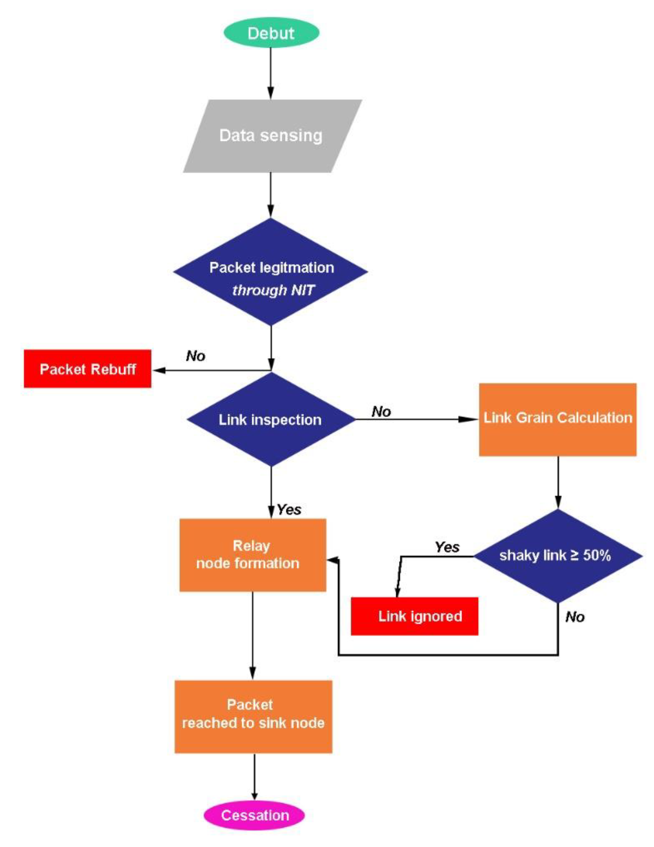
A resurrect link factor is a unique concept regarding hop link inspection. After sensing the data when a sensor node broadcasts packets toward neighbors, the hop link factor stimulates the link inspection process, as elaborated in Figure 1, flow chart. If the link threshold is found to be greater or equal to 50% of the energy shells, the receiving node acknowledges by add its residual energy information to the received packet and sending it back to the source node; upon receiving substantial acknowledge information the source node again sends the duplicate packet only that node and this time the duplicate packet possesses the extra energy shell which strengthens the link quality from 50% to 90% at most. Henceforth, a successful packet delivery is carried out, and therefore relay node formation is prone to complete. The complete methodology has been discussed in the Methodology section. This concept of resurrect link factor has not yet been investigated in other ground research.
The remaining discussions are arranged as follows: Section 2 highlights the related work, Section 3 covers the details of suggested (SURS-PES) routing methodology, the performance evaluation using simulation results are discussed in Section 4, and the conclusions and proposed future research directions are stated in Section 5.
2. Related Work
Acoustic communication is the only tranquil solution for underwater data routing due to its unique channel feature [8]. For terrestrial communication, the radio and electromagnetic waves are the best media because they cover a wide range of distance, but in the case of underwater they totally fail, therefore acoustic signals play the desired role in such an environment despite limited bandwidth and a propagation speed of about 1500 m/s which is considered to be very slow [9]. Nodes bearing low water pressure die early in the usual routing approach.
The acoustic signal debuts a propagation process through a unique medium in contrast to radio frequency. Although there are some obnoxious factors that cause energy drainage at large, the acoustic signal reflects, scatters and is observed by the seabed and water surface, and therefore transmission data is lost. The submerged acoustic signal operates between 10 Hz to 1 MHz frequencies. Due to a confined acoustic spectrum, only a limited range of frequencies are usable in underwater communication [10]. The unavoidable factors such as salinity, temperature, and water depth merely effect the speed of acoustic signal, therefore, the acoustic wave spreads into a curved path and sensor nodes cannot overhear the signals. As a result, it is prone to create a void area and nodes in this area cannot participate in the transmission process which eventually shortens the network lifespan.
Recharging or replacement of batteries are not easy tasks in underwater ocean especially in harsh environments, therefore, it is essential to design an efficient data routing protocol that can explore and maintain the routing path either from the bottom or the ocean surface in order to deliver the data packet according to the desired level with limited energy power.
While designing such an energy efficient underwater routing protocol, there are some uncouth challenges such as the bandwidth which is distant dependent and, in the case of long-range transmission, it presages high energy utilization and also transmission path losses. In addition, it possesses a higher propagation delay because the speed of acoustic signal in underwater is very low [11], although there are many routing protocols in practice that claim to be energy efficient but require a specific routing path every time during transmission; and in fact these are expensive and consume exorbitant energy [12]. Most of the routing approaches do not consider the link quality, therefore, energy is wasted by retransmission of hollow links. The performance attributes of relevant underwater opportunistic routing (OR) protocols are analyzed according to their class structure.
2.1. Location-Based Opportunistic Routing
On the basis of location information of sensor nodes, OR creates an imaginary virtual three-dimensional (3D) pipe from the relay to the sink node to avoid the issue of forwarder set selection (FSR). An energy harvesting-based routing scheme (ARCUN) [13], has been suggested with fixed ratio combining technique (FRC) to strengthen the smart use of energy utilization with controlled data packet load without putting in the medium access control. From the results, it seems that this technique puts extra data forwarding load on the relay nodes which shortens the network lifespan such situation.
A directional packet flooding was adopted by Ahmed, S. et al. [14], as a directional flooding—based routing protocol (DFR) where each node is aware of its own location with single hop neighbors’ location, and the position of the sink node is also recorded. In order to forward a packet, the link quality determines the flooding zone between the source node and the sink node. Although this method results in a pristine packet delivery ratio with trivial overhead, no measures are taken to address void occurrences and it is not suitable in a sparse environment.
Vijayalakshmi, P. et al. [15] developed a vector-based forwarding (VBF) stateless routing protocol, where the packet routes between the source node and the sink node along a redundant and interleaved path, and therefore only a few nodes participate in the forwarding process. The redundant paths are maintained by a self-adaptive algorithm and nodes freely choose the best path to forward the packet. When the destination node receives packet, it computes its relative position and records the distance from the forwarder with angle of arrival (AOA) adjacent to the vector. Despite its robustness for packet loss and node failure, it is only suitable for a small network and becomes uncouth in multi-sink environments.
Khasawneh, A. et al. [16] proposed a pressure-based location-free underwater routing protocol (RE-PBR) that mainly took into account the link quality, depth information, and residual energy. They utilized the triangle method to investigate the link quality and developed a multi-metric data forwarding algorithm to calculate the route cost. This method is only suitable for trivial networks and does not offer void handling technique.
A cooperative routing technique (US-ASNs) was developed by Hoa Tran [17] by taking MAC and the network layer together in a cross-layer design to make the link stronger. The data are forwarded following the routing relay technique, while communication is held with cooperative relays. The source node sends the packet with respect to factors such as SNR and the time of arrival. The concept seems obvious, but could this technique operate in a linear environment although it likes to diminish the packet delivery chain because no medium state has been specified, whether in deep or shallow water. In addition, the results were presented without putting in the void area which apparently would seem to be a shrewd approach.
2.2. Location-Free Opportunistic Routing
On the basis of the number of hop-counts and using dynamic address and pressure information the suburb nodes are identified. The sink node timely generates the beacon messages which travel from the water surface towards the inner depth with a unique identification called dynamic address. Different beacon-based protocols are used for different network topologies, all with various information-like addresses assigned to the sensor nodes. As location-free OR uses the topology information to find the forwarding rely nodes, to eliminate FSR, with the 2H-ACK [18] protocol, each node is bound with a dynamic address such as a beacon message, the neighboring node having a smaller address and closer to the sink is ranked super, as well as the member of the forwarding set nodes and the node with smallest address are selected as the next hop node. To tackle the DFS issue in the presence of unreliable link it only considers the single next forwarder node which is not a placate method.
Ashraf, S. et al. [19] proposed a lower power listening (LPL) mechanism to monitor the faulty nodes and energy wastage through ContikiMAC Cooja in UWSN. The energy consumption was reduced in centralized and distribute approaches. The author determined the energy consumption with end-to-end delay by proposing a stochastic model for UWSN, however, the model considered cylindrical propagation but not common spherical propagation.
A combative scheme of energy-aware and void-avoidance routing was reported by Wang, Z. et al. (EAVARP) [20], in which they built concentric shells around the sink node and sensor nodes were dynamically placed within these shells. Additionally, they adopted an opportunistic directional forwarding scheme (ODFS), where data packets within the same shell with a remaining amount of energy were forwarded which bypassed any void region if it occurred. Although the authors proposed a smart shortcut it could not follow the energy wastage scheme which ultimately shortened the network’s lifespan.
A decentralized and routing tables dependent strategy, namely Self-Organizing and Scalable Routing Protocol (SOSRP) [21] has been presented which enumerated the total number of hops from the source to the sink node. Routes were self-restructured, thereby isolating the inactive nodes. This scheme is well suited only for a small network and unable to control exorbitant packet flooding. No control over energy consumption is suggested, thereby nodes seem to die earlier than the expected duration. Every node utilizes the full energy cost while broadcasting the packets. After each transmission round, nodes restructure the routes which, therefore, ultimately increases the energy cost. Among the location-free routing series, the void problem has been solved by Barbeau, M. et al. [22], with location-free link state routing (LFLSR). Selection of the next forwarding hope node depends on the following three factors: (i) the hope count, (ii) route, and (iii) depth status. The route from the sink to the source node is handled by a beacon message that updates the route information. It requires a higher power consumption while using the pressure device to measure the path [23]. A summary of a stringent comparison of the proposed (SURS-PES) method with other routing protocols is highlighted in Table 1.
3. Proposed Methodology
A meticulous study has been conducted for a robust and energy efficient underwater mechanism which unveiled the idea of a Shrewd Underwater Routing Synergy by utilizing the Porous Energy Shells (SURS-PES). The selection of a shrewd link quality and packet forwarding mechanism has been thoroughly investigated, thereby, the mechanism of relay node formation is presented in Figure 2.
3.1. Operational Model
The proposed network architecture (SURS-PES) mainly contains sensor nodes, deployed at varying depth positions where the sink node, located at the upper water surface, communicates with the offshore base station which is out of the water. The sink node receives data packets from the source, as well as from neighboring relay nodes. It is packed with acoustic and RF modems. The acoustic modem pertains to communication with the underwater deployed sensor nodes, whereas the RF modem devolves for sending information to the base station. A successful data packet reaches the surface sink through hop-by-hop routing rovers through intermediate neighboring relay nodes. Every node obtains its depth information through depth sensor, while residual energy is recorded through distributed beaconing.
At the receiving node, the distance from neighboring relay node is ratified through received signal strength (RSS) [24], and signal attenuation depends on spreading loss which can be determine by the Thorp formula. For a particular frequency f, absorption loss α(f) is expressed in Equation (1):
where α(f) is rated in dB = km, f is the frequency in kHz, and α is equal to the absorption loss which is given as . The attenuation A(1, f) is obtained by the cumulative loss, whereas spreading is given in Equation (2):
where k × logl is a spreading loss with distance l, l × 10 log(α(f)) indicates the absorption loss, and coefficient k depicts the signal propagation geometry.
3.2. Link Factor
The energy consumption, data delivery ratio, and network throughput depend on link stability. The expected transmission count (ETX) based protocol, in fact, measures the link quality in the course of the forwarding process between two directions of each link. These protocols utilize certain location information from GPS or acquire finite information from the sink node, whereas the proposed (SURS-PES) methodology determines the link quality by taking all measures at their best. Although some other link measuring techniques are in practice such as a cost-based routing, window mean of exponentially weighted moving average (WMEWMA) computes the memory efficient link estimator. A required number of packet (RNP) is a sender-side estimator that mainly handles the number of transmitted and retransmitted packets before the successful reception during an estimation window. The packet reception ratio (PRR) is a receiver side link estimator and its efficiency depends on the adjustment of the time window size thereof. All these link estimators have inoperable limitations, and therefore, thus far, a pristine link has not yet been successfully calculated. The proposed (SURS-PES) research was explicitly put through a unique facet to compute the pristine link factor undergo the following steps accordingly:
Step 1 Link factor indicator (LFI) and signal-to-noise ratio SNR computation
Let n be the absolute transmitted data packets, while m considered the successful packets acknowledged by the destination, whereas i stands for the packet successfully received after estimating its link quality by computing (link factor indicator) lfi of i and (signal-to-noise ratio) snri, accordingly. Considering link factor as a hardware-based metric, analyze if link has an acceptable quality range, then node has entry in the neighbor table. The SNR incorporates the amplitude of the received signal and the background noise together and computes the signal ratio. The obtained mean of lfi and snri testifies that higher LFI and SNR values could proceed to revitalize the link factor.
Step 2 LFI and SNR mean computation
An overall mean suffers from unavoidable limitations. It cannot handle the packet loss but indeed keeps track of the received nodes. Adding a priority metric either from (0,0) to (, ) adjusts the link factor. The mean ( along ) based on lfii, snri and PRR have been calculated by PRR metric, and forgo the statistical mean. The final values are obtained as Equations (3) and (4).
Step 3 Distance measurement
A link factor is determined by computing the path dΔ from the origin state (0, 0) to point (, ), thereby Equation (5) forms as
Step 4 Best path
Although the longest path between source and neighboring nodes dΔ presages as a best link quality but not a qualified pristine link, a predefined threshold th value can distinguish the link factor among all, as expressed in Equation (6):
The proposed (SURS-PES) mechanism is based on triangle metric (TM), thereby, the link quality is determined between the source and neighboring node and maintains a link repository table (LRT). The threshold parameters upon which link factor is determined are shown in Table 2.
3.3. Information Gathering Cycle
Every sensor node fetches information from surrounding nodes located at lower depth than its own, and thereby sends a hello message containing ID, depth, and residual energy within transmission range. Upon receiving this message, every node follows a stipulated sequence and archives the information in a neighboring information table (NIT) to ratify the eligibility of the message and accepted if depth is lesser, otherwise rebuff it.
First, TM analyzes the link quality by computing the accumulated SNR, LFI, and PRR values. The estimation process debuts as the sensor node broadcasts a probe packet containing ID, SNR, and LFI values thereon. In the next phase, PRR generates mean values while a link quality is estimated by calculating the distance based on the TM values. The final round updates the NIT table by entering individual nodes’ distance, whereas a priority rank is set for a higher distance node. Algorithm 1 vouches the information retrieving sequence, and thereby dissemination is expressed in steps as follows:
- Step 1 Each sensor node (nodea) creates a hello message (CreateHello) and sends towards neighboring nodes;
- Step 2 All neighboring node receives (CreateHello) message and performs the necessary actions;
- Step 3 NIT table continuously updates the nodes’ information because of periodic changes in the positions.
| Algorithm 1. Information retrieving. | |
| 1: | ProcedureCreateHello(nodea) |
| 2: | if HelloLatency is vanished then |
| 3: | Create Hellopacket |
| 4: | Includeid, depth, andresidual energy in HelloPacket |
| 5: | Broadcast (HelloPacket) |
| 6: | Set NewInterval |
| 7: | end if |
| 8: | end Procedure |
| 9: | |
| 10: | Procedure GetHello(nodea, HelloPacket) |
| 11: | if |nodea.depth|>|HelloPacket.depth| then |
| 12: | if HelloPacket id is invalid in nodea.NITthen |
| 13: | Include HelloPacket information to nodea.NIT |
| 14: | else |
| 15: | update information in nodea.NIT |
| 16: | end if |
| 17: | goto link factor triangle metric(nodea) |
| 18: | else |
| 19: | rebuff(HelloPacket) |
| 20: | end if |
| 21: | end Procedure |
3.4. Packet Forwarding and Route Cost
Data packets initiate traveling from the source to the destination sink node and all nodes actively take part in the packet forwarding process, but a higher packet delivery ratio is only possible when the next forwarding node lies close to a destination sink node with better link and greater residual energy. Nevertheless, Wahid, A [25], computed a limited cost factor depending on either residual energy or ETX. However, we put forth the residual energy to determine the route cost, and therefore calculated the TM-based distance. Henceforth, the route cost between two nodes, i.e., (x,y) has been evaluating as expressed in Equation (7).
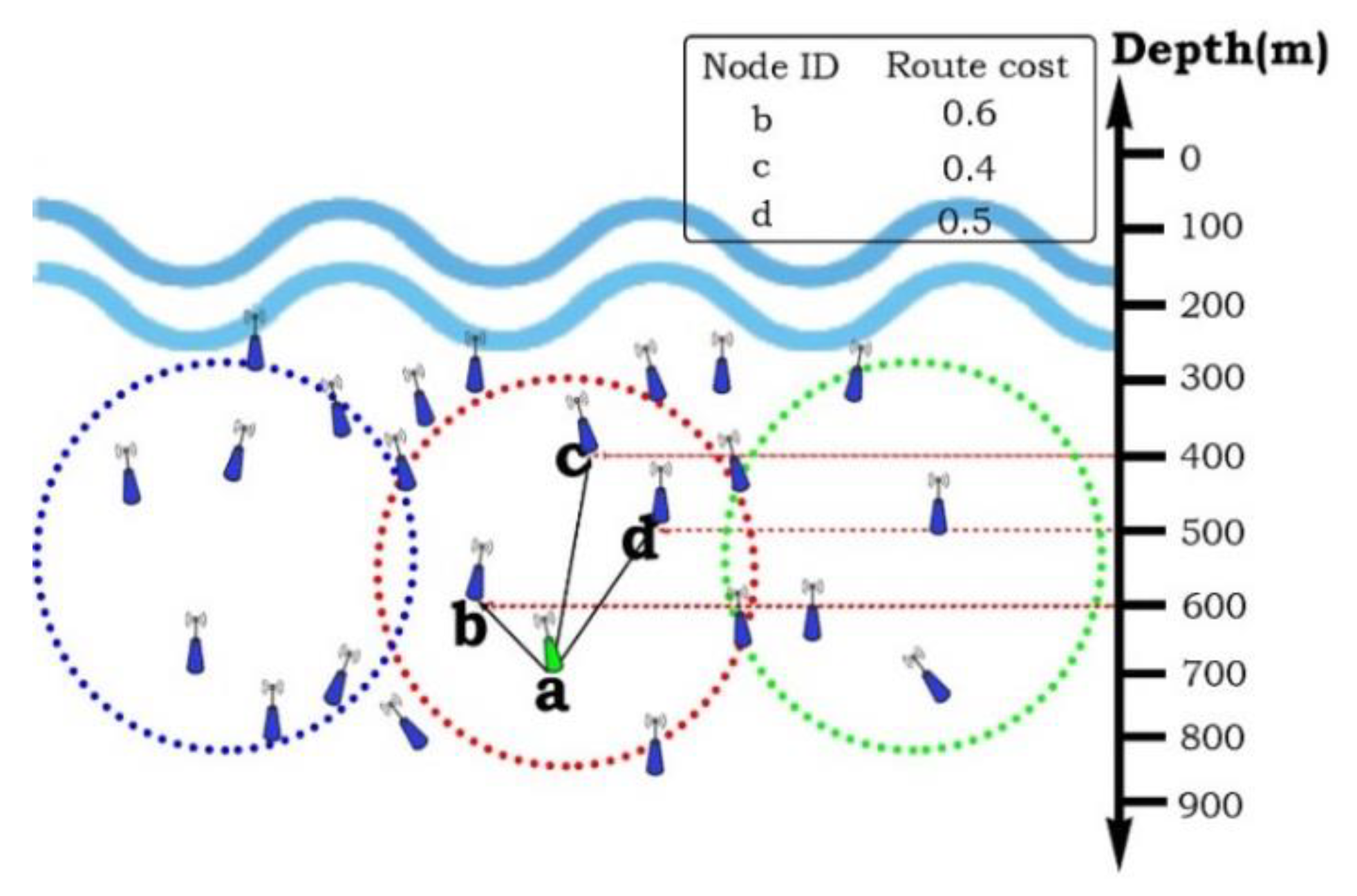
The residual energy of node y is represented by Resy, Resmax depicts the entire nodes’ energy, and ∆dmax is an environment specified system parameter. The link quality parameters between the sender and forwarder nodes has been obtained as ∆d(x,y). Taking two different metrics into an account, i.e., residual energy and link quality, Equation (7) is used to evaluate the route cost of the proposed scheme. From this equation, it is observed that to keep the route cost minimum, the node must have a lower depth than the sender node and resulting shrewd link quality. Proceeding to select the next forwarding relay node, as depicted in Figure 3, the sender node, a, initially inquires the information of nearby nodes from NIT. In the next phase, it calculates the route cost with Equation (7). The node that possessed the lower route cost is selected, here in this case, the selected node is b. Algorithm 2 explicitly performs the plausible packet forwarding mechanism.
The sender node, a, encapsulates its ID into data packet and broadcasts it towards the next hop neighbors. At the receiving node, the packet ID is matched with the receiving node’s ID and if it found valid the packet is accepted, otherwise it rebuffs the packet. By repeating the same procedure, finally, the data packet is reached at the destination sink node. Due to uncouth UWSNs, the data packet could encounter some hindrance when revering towards the final destination [26]; the packet passes through different regions and could loss at any location.
| Algorithm 2. Packet Forwarding. | |
| 1: | ProcedureForwardPacket(nodea, packetp) |
| 2: | if nodea ID match = receiving ID for packetpthen |
| 3: | Compute route cost |
| 4: | include route cost (x,y) into NIT |
| 5: | else Rebuff(packetp) |
| 6: | end if |
| 7: | Select highest priority node with route cost |
| 8: | include nodea ID = (x, Resy)thereupon |
| 9: | nodea retains packet |
| 10: | Obtain link factor between sender nodea and forwarder b ←∆d(x,y) |
| 11: | Generates retransmission time |
| 12: | Rebroadcast packetp ←Update NIT |
| 13: | if nodea retains lower depth than nodeb ←∆d(x,y) then |
| 14: | select forwarder nodeb |
| 15: | else Rebuff(packetp) |
| 16: | end if |
| 17: | endProcedure |
3.5. Link Grain Calculation
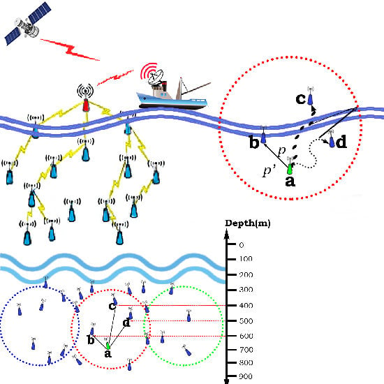
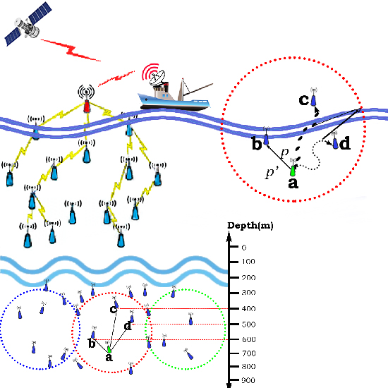
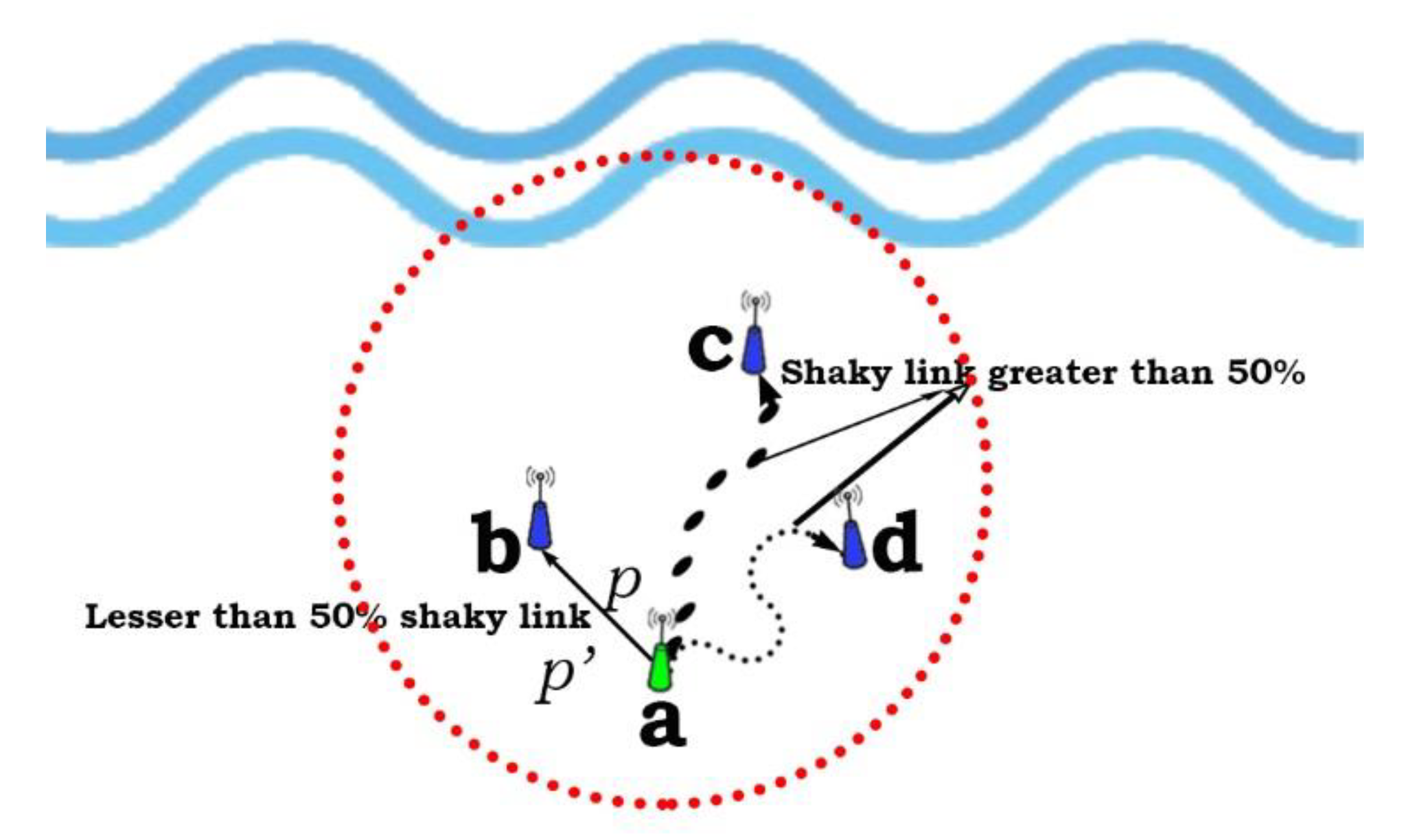
The proposed mechanism computes and maintains a more desirable link quality, and thereby enhances the concept of link reparation. When the sensor node, a, broadcasts the packet, p, with substantial information such as depth, ID, and residual energy towards neighboring nodes, i.e., b, c, and d, as illustrated in Figure 4. For instance, a source node, Na is broadcasting the packet towards neighbors, upon receiving this packet node b includes the necessary information and sends it back as Nbp’ to node a.
After adding the required energy shells and making a duplicate node a, again multicasts the packet only to node b as Na2p within a trivial time t. The final link grain is calculated as expressed in Equation (8):
Finally, the link quality is optimized with energy consumption , and , respectively which remains unaltered, and therefore Equation (9), in due course, updates the link status probability from 50% to a 90%.
The communication links between node a and other nodes are being analyzed. Thereon, a stipulated link quality inspection is carried out which reports whichever hop links are more than 50% ramshackle and what links are more stable than 50% at all. For example, link quality between source node a and b is more than 50% stable but not up to 90%, thereon, links between node a to c and to d are more than 50% unstable. Thereupon Algorithm 3 renders how the shrewd link selection process is being achieved for the proposed methodology (SURS-PES), thereby, the hop link between node a and b make it more stable, i.e., up to 90% to accomplish the smooth packet transmission. Continuing to receive packet p by node b adds the acknowledgment packet and residual energy information which, thereby, sends packet p’ back to node a. Upon receiving packet p’, node a analyzes the position and status of node b and adds the extra energy shells to strengthen the link quality, and finally transmit the same packet in the form of duplication only to node b.
At this point our proposed idea is more viable which utilizes a sender cognitive technique, i.e., continuously overhears the forwarders’ packet and maintains a time-dependent corpus. It retains the packet in the corpus; when the receiving node overhears the same packet, the packet already stored in the repository is removed, and therefore avoids the retransmission fistula.
| Algorithm 3. Link grain computation. | |
| 1: | Procedure nodea (Nap)broadcasts packetp ←(Depth, ID, Residual energy) |
| 2: | Compute Link state node(a, b, c) ≤ 50% shaky |
| 3: | if nodeb ≤ 50% shaky then |
| 4: | nodeb ID match = receiving ID of packetp |
| 5: | end if |
| 6: | nodeb update NIT and send Nbp’ back to nodea |
| 7: | nodea update (), duplicate packetp () |
| 8: | If ←90% |
| 9: | Updates (Link state, NIT) |
| 10: | else Rebuff(packetp) |
| 11: | end if |
| 12: | endProcedure |
3.6. Multipath Reflection
In shallow water, boundary reflection causes multipath scattering, which mainly adds the delay factor in underwater acoustic communication. An upper surface disorders the sound propagation, while in deep water it is affected by the bottom surface. All these make the acoustic data difficult for smooth communication. A horizontal acoustic channel becomes more fragile than vertical channel, and the wavelength disperses but frequency remains unaltered [27]. Acoustic signal propagation is also affected by the surface gravity, especially when modem signals impinge to water surface [28]. The multipath acoustic signal propagation in shallow water is illustrated in Figure 5. It is a specular on a dynamic sea surface, as well as at a stationary bottom. The dynamic surface surrogates the high-tech acoustic energy, while the bottom surface is diffused with scattering caused by the sediment. Multipath creates braids that have stringent topological connections which are less diffused in nature. At the upper water surface, the gravity wave strongly affects signal propagation which causes the production of air bubbles, thereof, it observes sound and converts into slow-speed signals. If wind speed increases, the scattered bubble absorbs the acoustic energy which could block the channel. The volume fluctuation causes the variability of a refracted path. Due to ambient noise, fish migration, and eddies inject fluctuation into the acoustic channel. Apparently, the authors of [29] proposed a temporal multipath scattering solution by taking constant sound velocity C and uniform depth h which is hardly possible.
Furthermore, putting in the first and last boundary reflection of n order of multipath signals, named as first, second, and third multipath, i.e., SBn, BSn, and BBn, respectively, the direct path reflection and reflection of four different paths are computed, and thereon expressed in Equations (10)–(13) respectively.
where a and b point the height of transmitter and receiver from bottom surface and the distance between the transmitter and receiver is indicated by L. This scattering model proves that if L becomes larger, there shall be a trivial difference in arrival time. As wave movement occurs, the value of a, b, and L varies. Surrogating the equation, thereby sustainable arrival time related to different paths are finally achieved with Equation (14) as
This equation ratifies the pristine improvement by settling the difference of multipath reflection and it could be sustained until L remains greater than h.
4. Performance Evaluation
The performance of the proposed methodology was meticulously evaluated by comparing it with DBR and EEDBR protocols using NS2 simulator and encompasses with Aqua-Sim. The simulation setup parameters were applied, as listed in Table 3 accordingly. For this evaluation, 100 to 400 sensor nodes were considered in the network size of about 1000 x 1000 x 900 m3 with a fixed distance of 100 m between every sensor couplet. When the simulation debuts the operation, during the hello packets interval, i.e., 99 s, the neighboring nodes overhear the depth and residual energy, thereupon distance-based TM is computed, while keeping the energy model [30], as a base instance, estimates the residual energy and energy consumption as well. After completing 99 transmissions, we considered only half and built the results.
4.1. Point-to-Point Impediment
An entire or thereabout duration by which packet rovers from the source through various regions and get accepted at the final destination is known as point-to-point impediment. Sometimes unavoidable impediments from transmission, propagation, and signal processing are added unintentionally which slows down the packet transmission. Point-to-point impediment can be determined by Equation (15):
The entire packet corpus, when acknowledged at final destination, is defined as the lth simulation, and BTl,m indicates the broadcast time of mth packet. Similarly, at destination point, ATl,m represents the acknowledged time of mth packet thereof.
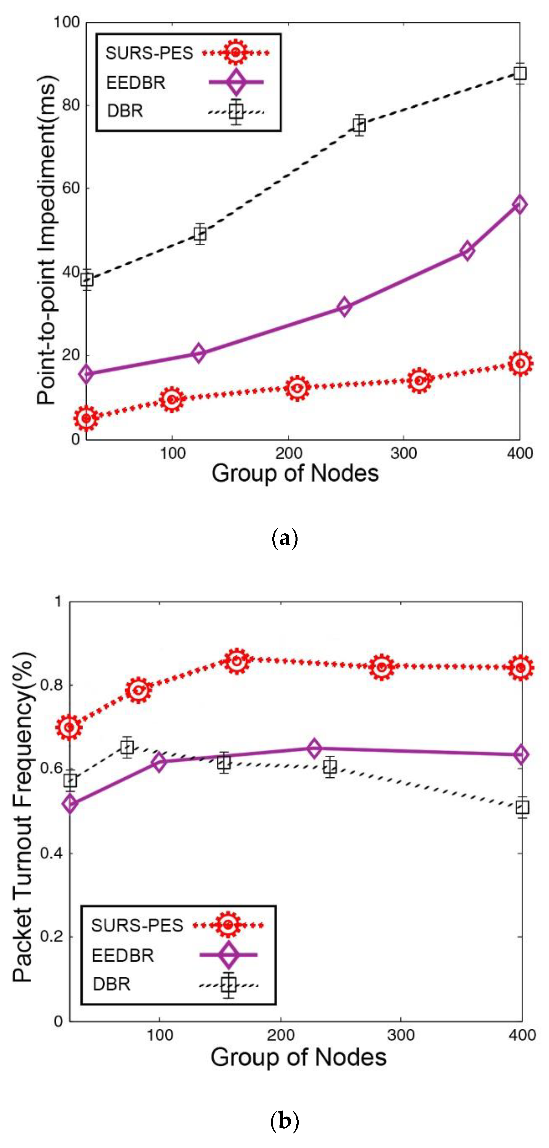
In underwater routing, packet holding time mostly causes the point-to-point impediment which has been avoided in the course of the proposed SURS-PES scheme. According to simulation results, Figure 6a ratifies that this delay is foremost lower than the rival protocols; it also confirms that such conditions remain the same for sparse and dense environments, despite even countless computations occurring during the transmission process. Packet holding time and depth information dependency create a big hassle for DBR not to perform well as compared with the proposed scheme SURS-PES. Furthermore, a trivial point-to-point delay in contrast to DBR is observed for EEDBR, because it utilized a residual energy-based packet holding mechanism, but if a sudden packet loss occurs the packet holding duration also increases, and therefore could cause an indefinite delay.
4.2. Packet Turnout Frequency
A numerical relation of broadcasted packets, when received at final destination, i.e., sink node in any form or quantity is known as a packet turnout frequency. Primarily this relation (PTF) is expressed in percentage, as stated in Equation (16).
During the nth simulation, PB and PR stipulate the broadcasted and received packet ratio. Adding substantial nodes can result in a shrewd packet turnout. Although DBR is best fitted on this statement and sufficient packet delivery improvement is seen, a packet holding time adds extra forwarding which could increase packet collision if the network changes state, i.e., sparse to dense. The unprecedented packet delivery frequency from SURS-PES is made possible in the course of astute link selection and higher residual energy. According to Figure 6b, at close to 160 nodes, the proposed scheme achieved a better delivery ratio than that of DBR and EEDBR, approximately 12% and 18%, respectively. While at the end of transmission when the number of nodes reached 500, the SURS-PES came up with an unbeatable score which was 22% and 12% as compare with DBR and EEDBR at most.
4.3. Network Lifespan
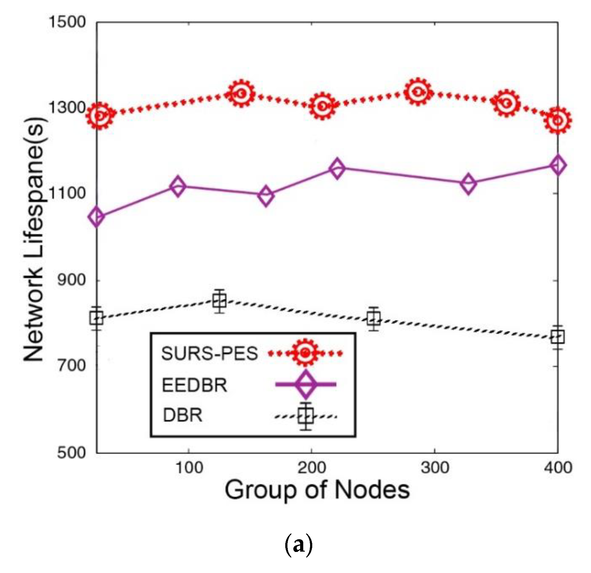
The optimal duration when sensor nodes actively send and receive the packets is known as the lifespan of the system. In order to achieve a longer lifespan, two approaches are in practice, i.e., schedule-based and range-based approaches. For the proposed SURS-PES method, a schedule-based approach set to S-MAC protocol [31,32] was used for the simulation results. An entire network lifespan encompassed the time from the first packet broadcast unless the last packet was acknowledged by the destination node, and thereupon network output. Equation (17) can be used to compute the network lifespan
where for a lth simulation, network triggers at NNTl times, and thereby halts at NHTl time. Statistics shows that if a group of nodes and field area increases simultaneously, ultimately network lifespan becomes trivial. However, if sensor nodes could shrewdly adjust transmission power among various levels, and therefore distribute the packet load among all nodes by the S-MAC activity, the network lifespan could be revitalized farther.
Therefore, the SURS-PES method outperformed as compared with its rivals, i.e., DBR and EEDBR, as illustrated in Figure 7a. The higher residual energy with shrewd link factor made it possible to extend the network lifespan during the forwarding process for SURS-PES. Furthermore, the proposed scheme did not carry any packet holding tangle, and therefore there was no redundant packet transmission impediment to the smooth transmission, no matter how often the network volume became dense or sparse. Therefore, the network achieved stability that could indeed lead to prolonging its lifespan. Analyzing the DBR performance, indeed its lifespan remained shorter throughout the transmission which led to not availing the residual energy, except the depth information which was only used for the forwarding node selection process. In addition, the nodes residing in shallow water cannot exist for longer times and can die quickly, therefore, leading to a network collapse. EEDBR performed with a deft touch as compare with DBR because the shrewd usage of residual energy and depth information made it worthwhile, thereof, it only confirmed that the number of nodes could participate in packet forwarding, hence, there were no more redundant packets in the results. Despite all, the performance of EEDBR could not approached, even close, the proposed SURS-PES scheme.
4.4. Energy Diminution
There is average energy utilization during transmission rounds by all nodes to deliver packets to the destination sink node. Equation (18) can be used for the determination of energy utilization by each sensor node. Therefore, a node consumes energy, thereof, transmits a p-bits as a beacon message over distance d, henceforth:
where p.Eds is a signal dissipation, p.Efs shows a free space, and multipath is indicated through p.Emp. A p bits energy packet is received by the sensor node, thereby, it engulfs Ee amount of energy depicted in Equation (19):
when forwarder relay node sends p-bits packet towards the destination sink node, thereby, consumes Ef (p,d) energy ratifies in Equation (20), where Ef is an energy to be consumed during packet forwarding by the sensor node.
Summarizing for energy steps, the final and a pristine output was unveiled through Equation (21) which explicitly exhibits the amount of energy consumed during packet forwarding by the sensor nodes up to the destination sink node.
In continuous performance, the proposed SUR-PES methodology has come up with the desired energy consumption results, as illustrated in Figure 7b. It consumed only trivial energy during the entire period as compared with DBR and EEDBR. No doubt this desirable performance has only been achieved due to the impediment of redundant packet transmission. In addition, the smart aspects of residual energy and link quality have been availed to make usage of energy at a confine most. Although, this technique is not useful at every stage, thereon, SURS-PES initially faced this situation, and thereby, an energy consumption frequency was slightly higher but soon the forwarder node made adjustments and overall consumption reached an acceptable level. At approximately 290 to 600 nodes, the energy consumption ratio becomes linear which indicates that the routes are smooth and packet loss is almost negligible, therefore, all packets are reverting to sink node without wasting extra energy shells. The output enumerates about 27% and 32% less energy consumption as compared with EEDBR and DBR, which is a foremost achievement in this situation.
Although EEDBR performed much better than DBR and could balance the energy utilization by availing all factors, i.e., residual energy, depth information, and avoiding redundant transmission but failed to deal with increasing quantity of nodes, consequently, the energy consumption put it at higher risk to die soon. While analyzing the DBR performance, apparently the energy consumption was recorder at peaks, because of no usage of residual energy and with redundant packet transmission it seems vulnerable for the rest of the protocols.
4.5. Results at a Glance
The point-to-point impediment avoids the packet holding time which causes a belated attempt to packet transmission. The packet holding time and residual energy do not permit DBR and EEDBR to perform well as compared with the proposed SURS-PES methodology. For packet turnout frequency, when the network state changes either from dense to sparse, the packet holding time generated extra forwarding for DBR and EEDBR which ultimately increased the packet collision and the network could bottleneck. The SURS-PES method availed a shrewd link selection technique, thereby, at the end of transmission it produced 22% and 12% better output as compared with DBR and EEDBR. The usage of the MAC based (S-MAC) protocol by the proposed SURS-PES not only made the network lifespan longer but also came up with shrewd energy consumption. The sensor nodes adjusted the power transmission which led to balance the packet load for the entire network, thereby, redundant packet transmission was rebuffed. Transmission related to DBR and EEDBR became fragile for such long time and produced useless output.
5. Conclusions and Future Directions
For underwater routing, only shrewd protocols can make the network long-lasting. Therefore, the role of batteries becomes significant and crucial, as the entire transmission is battery dependent and if shrewd protocols make judicious usage of limited battery volume then the expected results are achieved. The proposed SURS-PES methodology did the same job as it was expected to at design time. Applying resurrect link ability with residual energy and depth information made it possible to select the next more desirable forwarding node as compared to other traditional approaches. Therefore, comprehensive results are obtained in terms of point-to-point impediment, packet turnout frequency, network lifespan, and energy diminution, which were never expected through traditional routing schemes. Revitalizing the link quality through link grain calculation is a unique idea that takes into account the link status among source to neighboring nodes and scrutinizes the link qualities as ramshackle less than 50% and greater than 50%, separately. When a link is equal or less than 50% shaky, a source node adds extra energy shell by considering the residual energy of the targeted node and makes the link up to 90% shrewd, thereon packet becomes duplicate and stabilize link for smooth delivery. We anticipate future study with smart exploitation of artificial intelligence to enhance the UWSNs’ bandwidth utilization by segment allotment technique which intends to maintain the sustainable network in line with ubiquitous monitoring (See Supplementary Materials).
Supplementary Materials
For readers, supporting data has been placed on google drive for a limited time due to google policies, however, for any discrepancy the explanation is available upon request https://drive.google.com/open?id=11QArJX3phSNjGqW4yFbGyQgCFXwbL6Fy.
Author Contributions
Conceptualization and software by, S.A.; methodology, T.A.; validation, S.A.; formal analysis, H.N.; investigation, S.A.; resources, A.R.; data curation, writing—original draft preparation, writing—review and editing, S.A.; visualization and supervision, S.A. All authors have read and agreed to the published version of the manuscript.
Funding
This research received no external funding at all.
Conflicts of Interest
The authors declare no conflict of interest at all.
References
- Coutinho, R.W.L.; Boukerche, A.; Vieira, L.F.M.; Loureiro, A.A.F. Geographic and Opportunistic Routing for Underwater Sensor Networks. IEEE Trans. Comput. 2016, 65, 548–561. [Google Scholar] [CrossRef]
- Ghoreyshi, S.; Shahrabi, A.; Boutaleb, T. A Novel Cooperative Opportunistic Routing Scheme for Underwater Sensor Networks. Sensors 2016, 16, 297. [Google Scholar] [CrossRef] [PubMed]
- Arioua, M.; El Assari, Y.; Ez-Zazi, I.; El Oualkadi, A. Multi-hop cluster based routing approach for wireless sensor networks. Procedia Comput. Sci. 2016, 83, 584–591. [Google Scholar] [CrossRef] [Green Version]
- Lloret, J.; Garcia, M.; Sendra, S.; Lloret, G. An underwater wireless group-based sensor network for marine fish farms sustainability monitoring. Telecommun. Syst. 2014, 60, 67–84. [Google Scholar] [CrossRef]
- Majid, A.; Azam, I.; Waheed, A.; Zain-ul-Abidin, M.; Hafeez, T.; Khan, Z.A.; Qasim, U.; Javaid, N. An Energy Efficient and Balanced Energy Consumption Cluster Based Routing Protocol for Underwater Wireless Sensor Networks. In Proceedings of the 2016 IEEE 30th International Conference (AINA), Crans-Montana, Switzerland, 23–25 March 2016. [Google Scholar] [CrossRef]
- Faheem, M.; Tuna, G.; Gungor, V.C. QERP: Quality-of-Service (QoS) Aware Evolutionary Routing Protocol for Underwater Wireless Sensor Networks. IEEE Syst. J. 2018, 12, 2066–2073. [Google Scholar] [CrossRef]
- Wen, Y.; Gao, R.; Zhao, H. Energy Efficient Moving Target Tracking in Wireless Sensor Networks. Sensors 2016, 16, 29. [Google Scholar] [CrossRef]
- Springer International Publishing. New Frontiers in Quantitative Methods in Informatics. Communications in Computer and Information Science; Balsamo, S., Marin, A., Vicario, E., Eds.; Springer International Publishing: Manhattan, NY, USA, 2018. [Google Scholar] [CrossRef]
- Awan, K.M.; Shah, P.A.; Iqbal, K.; Gillani, S.; Ahmad, W.; Nam, Y. Underwater Wireless Sensor Networks: A Review of Recent Issues and Challenges. Wirel. Commun. Mob. Comput. 2019, 1–20. [Google Scholar] [CrossRef]
- Ashraf, S.; Gao, M.; Mingcheng, Z.; Ahmed, T.; Raza, A.; Naeem, H. USPF: Underwater Shrewd Packet Flooding Mechanism through Surrogate Holding Time. Wirel. Commun. Mob. Comput. 2020, 2020, 9625974. [Google Scholar] [CrossRef] [Green Version]
- Venkateswarulu, B.; Subbu, N.; Ramamurthy, S. An efficient routing protocol based on polar tracing function for underwater wireless sensor networks for mobility health monitoring system application. J. Med Syst. 2019, 43. [Google Scholar] [CrossRef]
- Patil, K.; Jafri, M.; Fiems, D.; Marin, A. Stochastic modeling of depth based routing in underwater sensor networks. Ad Hoc Netw. 2019, 89, 132–141. [Google Scholar] [CrossRef]
- Kim, S.; Choi, J.W. Optimal Deployment of Vector Sensor Nodes in Underwater Acoustic Sensor Networks. Sensors 2019, 19, 2885. [Google Scholar] [CrossRef] [PubMed] [Green Version]
- Ahmed, S.H.; Lee, S.; Park, J.; Kim, D.; Rawat, D.B. iDFR: Intelligent directional flooding-based routing protocols for underwater sensor networks. In Proceedings of the 2017 14th IEEE Annual Consumer Communications and Networing Conference (CCNC), Las Vegas, NV, USA, 8–11 January 2017. [Google Scholar] [CrossRef]
- Vijayalakshmi, P.; Noorunnisa, N.; Rajendran, V. Performance analysis of VBF protocol for position tracking of moving nodes in underwater communications. In Proceedings of the 2017 International Conference (ICCSP), Wuhan, China, 17–19 March 2017. [Google Scholar] [CrossRef]
- Khasawneh, A.; Latiff MS, B.A.; Kaiwartya, O.; Chizari, H. A reliable energy-efficient pressure-based routing protocol for underwater wireless sensor network. Wirel. Netw. 2017, 24, 2061–2075. [Google Scholar] [CrossRef]
- Tran-Dang, H.; Kim, D.S. Channel-aware cooperative routing in underwater acoustic sensor networks. J. Commun. Netw. 2019, 21, 33–44. [Google Scholar] [CrossRef]
- Wu, H.; Wang, J.; Ananta, R.R.; Kommareddy, V.R.; Wang, R.; Mohapatra, P. Prediction based opportunistic routing for maritime search and rescue wireless sensor network. J. Parallel Distrib. Comput. 2018, 111, 56–64. [Google Scholar] [CrossRef]
- Ashraf, S.; Gao, M.; Chen, Z.; Haider, S.K.; Raza, Z. Efficient Node Monitoring Mechanism in WSN using Contikimac Protocol. Int. J. Adv. Comput. Sci. Appl. 2017, 8, 152. [Google Scholar] [CrossRef]
- Wang, Z.; Han, G.; Qin, H.; Zhang, S.; Sui, Y. An Energy-Aware and Void-Avoidable Routing Protocol for Underwater Sensor Networks. Ieee Access 2018, 6, 7792–7801. [Google Scholar] [CrossRef]
- Hindu, S.K.; Hyder, W.; Luque-Nieto, M.-A.; Poncela, J.; Otero, P. Self-Organizing and Scalable Routing Protocol (SOSRP) for Underwater Acoustic Sensor Networks. Sensors 2019, 19, 3130. [Google Scholar] [CrossRef] [Green Version]
- Barbeau, M.; Blouin, S.; Cervera, G.; Garcia-Alfaro, J.; Kranakis, E. Location-free link state routing for underwater acoustic sensor networks. In Proceedings of the 2015 IEEE 28th Canadian Conference (CCECE), Halifax, NS, Canada, 3–6 May 2015. [Google Scholar] [CrossRef] [Green Version]
- Ahmad, A.; Barbeau, M.; Garcia-Alfaro, J.; Kassem, J.; Kranakis, E. Tuning the demodulation frequency based on a normalized trajectory model for mobile underwater acoustic communications. Trans. Emerg. Telecommun. Technol. 2019, 30. [Google Scholar] [CrossRef]
- Wu, Y.; Wang, K.; Sun, Y.; Ji, Y. R2NA: Received Signal Strength (RSS) Ratio-Based Node Authentication for Body Area Network. Sensors 2013, 13, 16512–16532. [Google Scholar] [CrossRef] [Green Version]
- Wahid, A.; Kim, D. An Energy Efficient Localization-Free Routing Protocol for Underwater Wireless Sensor Networks. Int. J. Distrib. Sens. Netw. 2012, 8, 307246. [Google Scholar] [CrossRef]
- Gupta, A.S.; McCarthy, R. Interpreting Different Features of Shallow Water Acoustic Channels Using Braid Manifolds. In Proceedings of the 2018 Fourth Underwater Communications and Networking Conference (UComms), Lerici, Italy, 28–30 August 2018. [Google Scholar] [CrossRef]
- Wahid, A.; Lee, S.; Jeong, H.; Kim, D. EEDBR: Energy-Efficient Depth-Based Routing Protocol for Underwater Wireless Sensor Networks. In Proceedings of the International Conference on Advanced Computer Science and Information Technology, Seoul, Korea, 27–29 September 2011. [Google Scholar] [CrossRef]
- Davis, L.; Zatman, M.; Pollard, R.; Eicke, J. Incoherent Resolution of Unresolved Surface Multipath. In Proceedings of the 2019 IEEE Radar Conference (RadarConf19), Boston, MA, USA, 22–26 April 2019. [Google Scholar] [CrossRef]
- Brulinski, K.; Rudzinski, A.; Stefani, A. Characterization of ultrasonic communication channel in swimming pool. In Proceedings of the 2019 Signal Processing Symposium (SPSympo), Krakow, Poland, 17–19 September 2019. [Google Scholar] [CrossRef]
- Sathish, M.; Arumugam, K.; Pari, S.N. Triangular metric based routing protocol for underwater wireless sensor network. In Proceedings of the 2nd International Conference for Convergence in Technology (I2CT), Mumbai, India, 7–9 April 2017. [Google Scholar] [CrossRef]
- Kalaivaani, P.T.; Rajeswari, A. An Energy Efficient Analysis of S-MAC And H-MAC Protocols for Wireless Sensor Networks. Int. J. Comput. Netw. Commun. 2013, 5, 83–94. [Google Scholar] [CrossRef]
- Khan, M.A.; Karim, M.R.; Kim, Y. A Scalable and Hybrid Intrusion Detection System Based on the Convolutional-LSTM Network. Symmetry 2019, 11, 583. [Google Scholar] [CrossRef] [Green Version]
Figure 1.
Proposed (SURS-PES) methodology flow chart.

Figure 2.
Modular topology.

Figure 3.
Relay node selection process.

Figure 4.
Link grain determination.

Figure 5.
Multipath reflection.

Figure 6.
Determination of data packet behavior during the transmission cycle. (a) Point-to-point impediment; and (b) packet turnout frequency.
Figure 6.
Determination of data packet behavior during the transmission cycle. (a) Point-to-point impediment; and (b) packet turnout frequency.

Figure 7.
Network lifespan vs. energy consumption. (a) Total network alive time and (b) energy utilization for entire transmission.
Figure 7.
Network lifespan vs. energy consumption. (a) Total network alive time and (b) energy utilization for entire transmission.


Table 1.
Comparative analysis of proposed methodology with other UW routing schemes.
| Protocol | Principle Area | Working Ground | Expediency | Impairments | Proposal (SURS-PES) |
|---|---|---|---|---|---|
| DBR by Costantino, G. et al. [13] | Depth information | Greedy routing technique | Better packet delivery ratio, lowest holding time | Energy swindler, high end to end delay, void holes, duplicate transmission | Limited energy usage, trivial end to end delay, better void handling, avoid duplication transmission |
| DFR by Ahmed, S. et al. [14] | Distance information and link quality (ETX) | Location aware (Own + next hop neighbor + sink node) | Reliable Packet delivery, petty overhead | Void area occurrence, inoperable for parse network, angle and reference based | Suitable for dense and spars network as well |
| VBF by Vijayalakshmi, P. et al. [15] | Distance information | Redundant and interleaved passage, Minimum distance to the sink inside the pipeline | Robust, scalable | Bottleneck in multi-sink environment | Selection of link quality tolerate the bottleneck situation |
| RE-PBR by Khasawneh, A. et al. [16] | Triangle metric | Multi-metric route cost | Link quality | Cannot handle void nodes | Smartly avoid the void communication |
| UW-ASNs by Tran-Dang et al. [17] | Cooperate routing | MAC and network layer together in a cross-layer design architecture | Link quality and network overhead | Uncouth energy wastage | Shrewd energy utilization |
| 2H-ACK by Wu, H. et al. [18] | Dynamic node address | Nodes near to sink are prioritized | Confined overhead | Unreliable link, having single forwarder | Multiforwarder environment, link selection is bound with link grain calculation |
| EAVARP by Wang, Z. et al. [20] | Opportunistic directional forwarding | Build concentric shells around the sink | Bypass the void region | Prone to energy waste, shorter network lifespan | Astute network lifespan |
| SOSRP by Hindu, S., [21] | Decentralized | Self-organized routes | Suitable for small network | Uncontrolled energy consumption | Always hindrance to wastage of energy |
| EEDBR by Wahid, A. | Depth and residual energy | Sender node obligate the forwarder | Confine energy consumption | Unreliable packet delivery | Shrewd packet delivery |
Table 2.
Types of link and threshold value.
| Metric Type | SNR | LFI | PRR | Triangle |
|---|---|---|---|---|
| Shrewd link | >30 | >106 | 1 | >145 |
| Pristine link | 15–30 | 102–106 | 0.75–1 | 80–145 |
| Fair link | 5–15 | 80–102 | 0.35–0.75 | 30–80 |
| Uncouth link | 0–5 | 0–80 | 0–0.35 | 0–30 |
Table 3.
Simulation setup parameters.
| Parameter | Value |
|---|---|
| Deployment area | 1000 × 1000 × 900 m3 |
| Distance among sensor couplet | 100 m |
| No. of nodes | [100–600] |
| Communication range | 250 m |
| Type of protocol | SMAC |
| Start energy | 100 J |
| Medium | Acoustic Waves |
| Bandwidth capacity | 10 Kbps |
| Packet generation rate | 0.02 pkts/min |
| Velocity | 1500 m/s |
| Node movement | 0–3 m/s |
| Energy consumption | 2 W; 0.75 W; 8 mW |
| Data packet volume | 64 bytes |
| Data packet interval (hello) | 99 s |
| Packet creation time | 15 s |
| No. of runs | 50 |
| Confidence interval convergence time (T f −99%) | −0.018; 0.038 |
| Confidence interval convergence distance (Df −99%) | −0.014; 0.0277 |
© 2020 by the authors. Licensee MDPI, Basel, Switzerland. This article is an open access article distributed under the terms and conditions of the Creative Commons Attribution (CC BY) license (http://creativecommons.org/licenses/by/4.0/).
Share and Cite
MDPI and ACS Style
Ashraf, S.; Ahmed, T.; Raza, A.; Naeem, H. Design of Shrewd Underwater Routing Synergy Using Porous Energy Shells. Smart Cities 2020, 3, 74-92. https://0-doi-org.brum.beds.ac.uk/10.3390/smartcities3010005
AMA Style
Ashraf S, Ahmed T, Raza A, Naeem H. Design of Shrewd Underwater Routing Synergy Using Porous Energy Shells. Smart Cities. 2020; 3(1):74-92. https://0-doi-org.brum.beds.ac.uk/10.3390/smartcities3010005
Chicago/Turabian StyleAshraf, Shahzad, Tauqeer Ahmed, Asif Raza, and Hamad Naeem. 2020. "Design of Shrewd Underwater Routing Synergy Using Porous Energy Shells" Smart Cities 3, no. 1: 74-92. https://0-doi-org.brum.beds.ac.uk/10.3390/smartcities3010005