
Development and Future Scope of Renewable Energy and Energy Storage Systems


1
Department of Mechanical Engineering, National Institute of Technology, Warangal 506004, Telangana, India
2
Department of Railroad and Electrical Engineering, Woosong University, Jayang Dong, Dong-Gu, Daejeon 34606, Korea
*
Author to whom correspondence should be addressed.
Smart Cities 2022, 5(2), 668-699; https://0-doi-org.brum.beds.ac.uk/10.3390/smartcities5020035
Submission received: 27 March 2022
/
Revised: 13 May 2022
/
Accepted: 15 May 2022
/
Published: 20 May 2022
Abstract
:This review study attempts to summarize available energy storage systems in order to accelerate the adoption of renewable energy. Inefficient energy storage systems have been shown to function as a deterrent to the implementation of sustainable development. It is therefore critical to conduct a thorough examination of existing and soon-to-be-developed energy storage technologies. Various scholarly publications in the fields of energy storage systems and renewable energy have been reviewed and summarized. Data and themes have been further highlighted with the use of appropriate figures and tables. Case studies and examples of major projects have also been researched to gain a better understanding of the energy storage technologies evaluated. An insightful analysis of present energy storage technologies and other possible innovations have been discovered with the use of suitable literature review and illustrations. This report also emphasizes the critical necessity for an efficient storage system if renewable energy is to be widely adopted.
1. Introduction
Renewable energy has proven to be the most viable path to long-term sustainability. The current energy sources have a wide range of negative consequences. The average air quality index has deteriorated as a result of the combustion of conventional energy sources such as fossil fuels and coal. Increased air pollutants are hazardous to health and contribute to the ozone layer’s depletion. It is not sustainable because the currently used energy sources are finite [1,2]. The first step toward sustainable development is to find alternatives to renewable energy sources [3]. As a result, renewable energy sources like sun, wind, hydropower, and biomass are being investigated to generate electricity. The recommended Sustainable Energy Development Strategies [4] are satisfied by the utilization of renewable energies. The study looks at some of the most significant breakthroughs in renewable energy. Despite how appealing it may appear to totally switch to sustainable energy sources for power generation, this is not viable without sufficient energy storage. As a result, energy storage systems have been investigated in this work [5] to compensate for the intermittent nature of renewable energy sources.
The compressed air energy storage system (CAES) is an energy storage system that uses the electric energy generated to compress air, store it in a suitable storage system, and then release it to fuel in a combustor to generate electric energy when needed [6]. The CAES is only commercially operational in Mcintosh, Texas, and Huntorf, Germany, with capacities of 110 MW and 290 MW and efficiencies ranging from 60% to 80%. Prior to combustion in the combustor, compressed air is usually held in caverns. Diabatic CAES, adiabatic-CAES, advanced adiabatic-CAES, and isothermal-CAES are some of the varieties of CAES discussed in this study [7]. The regenerative fuel cell is an energy storage system that uses hydrogen to store electricity. A PEM (proton exchange membrane) electrolysis cell, a PEM fuel cell, and a hydrogen storage system make up the cell. There have been various sorts of hydrogen manufacturing technologies discussed, with water electrolysis being the most widely used [8]. PEM electrolyzers turn water into hydrogen and oxygen as a by-product using electricity generated by electrolysis. After that, the hydrogen is kept in an appropriate storage system. The stored hydrogen and oxygen are subsequently converted back to water by the PEM fuel cell. Electrons are made to flow across an external circuit in this process, resulting in the reproduction of electricity [9].
Power-to-gas technology (PtG) is a methane-based energy storage system. Hydrogen gas is produced using the electricity generated during electrolysis [10,11]. Methane is made from hydrogen gas through a series of processes. Methane is employed for transportation because of its favorable physical qualities [12]. When energy is required, methane is used to generate it through a natural gas grid. While the majority of the processes in the PtG approach are consistent, the methanation (methane generation) process differs depending on the application [13,14]. Methanation can take place in two ways: biologically or catalytically. In the study, each of these methanation processes has been thoroughly examined. Over the last two decades, lithium-ion (Li-ion) battery storage systems have grown in popularity, with applications spanning from small to large capacities [15].
Li-ion batteries have an anode, cathode, and electrolyte, just as other batteries. The passage of lithium ions through the electrolyte from the anode to the cathode controls the flow of electricity in an external circuit. The ability of these batteries to produce high voltages and charge per unit mass and volume has been demonstrated [16]. Charging and discharging are the two stages of the Li-ion battery’s operation, and they have been examined using figures in this work [17]. The report also provides an outline of current improvements in Li-ion battery technology as well as large-scale projects that have been built employing the technology. A flywheel energy storage system is a mechanical device that uses rotational motion to store electricity. The revolving mass of a flywheel energy storage system is driven by a motor. The spinning force is employed to operate a turbine when energy is required [18,19]. The rotational speed of the flywheel is restored using the motor as the rotational speed of the flywheel decreases while replicating energy. In hybrid automobiles, engineers are also contemplating replacing the traditional nickel–hydride battery with a flywheel energy storage technology [20].
The energy storage device of stacked concrete blocks stores electricity as potential energy. Pumped hydro energy storage systems, on the other hand, store water at a higher elevation. Energy storage systems made of stacked concrete blocks store barrels of mass at an elevation. When the stored energy has to be reproduced, the mass is dropped from the height, and the descent drives a turbine that generates electricity using a generator. Energy Vault, a business located in Switzerland, invented this technology and built a prototype of the energy storage system in Milan. The prototype demonstrates that the energy storage device is suitable for home use, with an efficiency of 85%. Engineers want to improve efficiency and optimize settings to boost capacity with more study [21]. Redox flow batteries are used to convert electricity to chemical energy on a large scale for grid storage. They are made up of two soluble redox couples that work in a separate electrolyte tank. A membrane is used to pump the two soluble couples dissolved in liquids. Ion exchange occurs as a result of this. In most practical applications, the voltage varies from 1 to 2.43 V. Because the redox flow reactions in these batteries are reversible, the redox fuel battery is classified as a secondary battery system. The redox flow battery has better heat management properties and enables for increased safety [22,23,24].
This paper examines various energy storage systems and their development, acknowledging the need for efficient energy storage systems for the operation and production of renewable energies. It also looks at prospective energy storage technologies that have yet to be implemented. The aforementioned energy storage methods have shown promising results and are constantly being researched and improved. This study examines the aforementioned energy storage devices and explains the various improvements made to their rudimentary patents. While keeping a prominent position for sustainable growth, the study also provides a brief overview of renewable energy’s introduction and how energy storage technologies adapt and compensate for their inefficiencies. As a result, the literature review for this paper focused on energy storage systems, their development, renewable energies, and long-term development. For the reader’s benefit, detailed illustrations, as well as relevant equations and reactions, have been provided.
The following is how the rest of the review paper is organized: Renewable energies, compressed air energy storage, regenerative fuel cells, hydrogen storage, pumped hydro, power-to-gas technology, lithium-ion battery, flywheel energy storage, stacked concrete blocks energy storage, and redox flow battery have all been explored in the exact order, divided into several subsections. The references used to author this review paper are provided at the end.
2. Renewable Energies
Economies have encountered the need for a quantum jump in energy production over the past few decades. Most modern-day industries thrive on fossil fuels. Fossil fuels when burnt release harmful pollutants into the atmosphere. Agents such as coal, gasoline, and oil are combusted to produce electric energy which results in a harmful hike in carbon monoxide levels in the air [25,26,27,28,29,30]. Countries and industries today are willingly adopting methods of sustainable development: tapping on renewable sources of energy to sustain current industrial growth. The adopted Sustainable Energy Development Strategies primarily revolve around three beliefs: Firstly, reducing energy demand and consuming energy judiciously. Secondly, energy tapped must be used as much as possible, i.e., the efficiency of energy production processes must be improved. Finally, renewable energies must be adopted as primary energy sources hence, replacing fossil fuels [31,32,33,34,35]. As an attempt to foster the principles of sustainable development, large-scale renewable energy projects and advancements are taking place. Engineers envision a world that will be completely powered by renewable energies [36,37,38,39,40]. Currently, solar energy from the sun, wind energy, biomass from plants, hydropower from flowing water bodies, and geothermal energy from the heat inside the earth are the most commonly applied renewable sources of energy [41,42,43,44,45]. In the solar energy domain, a new type of technology called thermophotovoltaics is gaining popularity. However, for the functioning of thermophotovoltaics, the heat is mostly produced using fuel and inputted to the module; so, the main use of technologies such as thermophotovoltaics is to reduce waste heat of industries to produce electricity [45,46,47,48,49,50]. Figure 1 is a representation of the different stages of energy conversion in the thermophotovoltaic module.
In India, renewable energies such as wind and solar energy are rapidly emerging as alternatives to coal and fossil fuels [51,52,53,54,55]. Wind and solar energies are now being integrated into the same grid to resolve the intermittent nature of renewable energies sources and meet energy demand in the past three decades. The Ministry of New Renewable Energy, a development organ of the Indian government, estimates the country to generate electric power of at least 2000 MW via active renewable energy grids solar and 38,500 MW via wind energy by the year 2022 [56,57,58,59,60]. The rise of power electronics is playing a pivotal role in improving efficiencies and reducing the cost of wind and solar integrated power grids and other renewable energies [61,62,63,64,65,66,67,68]. Fast semiconductor switches can enable effortless and quick handling and switching of powers. Large-scale renewable energy power grids employ the use of suitable energy storage systems to prevent problems that arise due to fluctuating power and other disincentives. Energy storage systems twinned with renewable energy grids store excess electrical energy when the energy demands are high [68,69,70,71,72,73,74,75,76,77,78,79,80].
3. Compressed Air Energy Storage
In the race towards clean energy technology, compressed air energy storage (CAES) often appears as a formidable contestant. Causing a low impact on the environment, the CAES can be regarded as an upgraded version of the traditional gas turbine plant. Currently, the CAES operates for commercial use in two installations, namely Mcintosh, United States (1991) and in Huntorf, Germany (since 1978), producing 110 MW and 290 MW, respectively [81,82,83]. The CAES is based on a turbine energy system, but it separates the compression process from the expansion process. An intermediate stage is introduced in between the two main governing processes where the incoming air is compressed by compressors and stored in air-tight storage, such as underground caverns. This compressed air is then mixed with fuel to be combusted in a combustor and used to rotate a turbine. The turbine is finally used to generate electricity for a power grid. This way energy can be saved in the caverns and can be utilized during the peak energy consumption hours. The waste heat produced can also be tapped by a recuperator instead of being expelled into the atmosphere [84]. The typical rating of a CAES system ranges from 50 to 300 MW with its efficiency ranging from 60% to 80%. The compressor, expander, reservoir, combustor, control system, and generator are the primary components of any CAES [85,86]. The compressor employed for the purpose of a CAES system depends on the application. A large-scale CAES system pressure is about 8 MPa for which a multi-stage compressor can be used. Intercoolers and aftercoolers are also fitted to reduce the moisture content in compressed air. Both high- and low-pressure turbines are used. A control and monitoring system for mechanical and electrical systems, fuel storage, and handling are used. An underground salt cavern is the most preferred reservoir for a CAES system [87]. Over the past decade, several advancements in the CAES system have resulted in several upgrades to the rudimentary model. While the diabatic CAES (D-CAES) dissipated the heat of compression as waste heat, the adiabatic CAES (A-CAES) does not allow the heat to get wasted and instead it is stored in a perfectly insulated heat storage reservoir with the compressed air. An advanced adiabatic CAES (AA-CAES) store the heat used for compression in a heat reservoir and is utilized for the combustion process in the turbine’s energy generation. Isothermal CAES (I-CAES) uses an isothermal tank that maintains its temperature constantly during charging and discharging [88]. Compressed air is a heavy way of storing fuel; 300L air at 300 MPA amounts to 12 kWh.
Let A be the initial state and B be the final state. The absolute temperature T = TA = TB. p represents absolute pressure.
VA represents the volume of the unknown gas that is being compressed and VB represents the volume of the storage system. R is the gas constant.
If there is a constant pressure outside of the vessel, which is equal to the starting pressure {\displaystyle p_{A}}, the positive work of the outer pressure reduces the exploitable energy (negative value). This adds a term to the equation above:
Above is the equation that shows the stored energy W that is required to compress air from pressure with a volume of .
Figure 2 is a figure that explains different configurations of the CAES systems [43]. Figure 2a is a diagram explaining the working of a diabatic storage system. The heat produced during the compression process is not preserved by dissipation and is hence wasted. Figure 2b is a diagram explaining the working of an adiabatic storage system. The heat produced during the compression process is not dissipated and wasted but rather stored as such in the CAES storage facility. Figure 2c is a diagram explaining the working of the advanced adiabatic storage system. In this, the heat during compression is stored and utilized prior to the expansion process. Figure 2d is a diagram explaining the isothermal storage system. In this configuration, the heat during compression is not lost. The compressed air is stored at a constant temperature in the tank during the charging and discharging processes.
CAES has been increasingly viewed as the ideal technology that can transform wind energy systems into electricity supply amidst the increasing advent of renewable energy. In Denmark, engineers are aiming for a fully renewable energy system—wind/CAES system and biofuels. TES systems using latent heat storage with the help of phase change materials (PCM) have gained recent popularity. Integration of solid oxide fuel cells also provides load-following capabilities with very minimal reductions in inefficiency. This type of integration leads to zero direct CO2 emissions [89,90]. CAES has proven to show superior ability to store compressed air, preserve electricity, and handle reproduction of energy during peak hours. CAES has also proven to be very efficient in handling ramped-up intermediate energy needs. In past events of power failures, energy storage systems usually demand a small amount supply of electricity, which is inputted from outside to enable the system to resume operation. The CAES, however, does not require any external electric energy for it to resume operation. This ability is called black-start capability [91,92].
4. Regenerative Fuel Cell
Hydrogen fuel cells combined with renewable energy sources have grown in popularity since the hydrogen generation process does not emit any impurities and can be easily produced as a byproduct of numerous activities. Natural gas has dominated hydrogen generation in recent years, accounting for 50% of total output, followed by oil reforming, coal gasification, and water electrolysis, which account for 30%, 18%, and 3.9 percent, respectively. The purest form of hydrogen may be produced via water electrolysis. Leading engineers in the hydrogen industry choose water electrolysis because it creates higher-purity hydrogen while avoiding the use of fossil fuels. Its energy density is 20–30 Wh/L, that is, roughly 30% of a conventional lead–acid battery.
In order to produce pure hydrogen, electric energy from renewable energy sources such as wind and solar is used in the electrolysis process. This pure oxygen is stored and then used to generate electricity in a fuel cell during peak energy demand times [93]. Electrolysis cell, fuel cell, and hydrogen storage are the three primary components of an RFC. There are three types of electrolyzers: proton exchange membrane (PEM), alkaline electrolyzers, and solid oxide electrolyzers (SOEC). Electrolyzers are classified according to the type of electrolyte they utilize. A schematic illustration of the operation of a water regenerative fuel cell system is shown in Figure 3. Water is electrolyzed and degraded to produce hydrogen and oxygen in this diagram. The hydrogen is held in reserve for future energy production. The hydrogen is used as an energy storage device and is delivered to a fuel cell when it is needed to generate electricity [94].
4.1. PEM Electrolyzer
The PEM electrolyzer splits water into hydrogen and oxygen at their respective electrodes. Water is pumped via the anode. Water is split into O2 and and electrons. The ions travel into the proton exchange membrane (PEM). The PEM is a thin membrane—about 20 microns thick—which only conducts positively charged ions and prevents the passing of electrons. The electrons from the anode escape via an external circuit toward the cathode. At the cathode, the protons travel via the membrane to combine with the electrons to release hydrogen. Hence, oxygen and hydrogen are produced at the anode and cathode, respectively [95].
Usually, under acidic regimes and high voltages, a noble catalyst is employed, such as platinum, to catalyze the splitting of water at the anode. The prime PEM electrolysis components are membrane, ionomer solution, and anode and cathode electrocatalysts [96]. The prime advantage of using the PEM electrolyzers is that the PEM uses a solid polymer electrolyte instead of an aqueous electrolyte. Its compact design, the solidity of the electrolyte, and reduced thickness of the electrolyte resulting in reduced Ohmic losses and high current density between electrolyzers. The solidity of the electrolyte in the cell allows the use of a strong structure that enables the cell to function at high pressures. The solidity of the electrolyte also guarantees a low gas crossover rate. Due to this, when the power input is low, proton transport through the membrane is reduced in no time without any delay. The other two electrolyzers cannot perform part-load operations while the PEM electrolyzer can [97]. Figure 4 is a representation of the working of a PEM electrolysis cell. To the left is the anode where oxygen is produced as O atoms. The protons move through the solid electrolyte membrane toward the cathode. While this happens, the electrons are pushed through an external circuit, thus producing electricity. To the right is the cathode. At the cathode, the protons react with the electrons to release hydrogen gas.
4.2. PEM Fuel Cell
Hydrogen previously-stored after the electrolysis process is supplied to the fuel cell as a fuel at the anode. The hydrogen atoms are split into protons and electrons. While protons migrate toward the cathode through the membrane, the electrons flow through an external circuit. A platinum-based catalyst mixed with an ion-conducting polymer enables the hydrogen atoms to split into protons and electrons at the anode. At the cathode, the platinum catalyst enables oxygen reduction by reacting with the protons, hence, producing water [98].
The gas diffusion layer (GDL) is sandwiched between the electrodes and the PEM. The GDL helps in transporting the ions to the catalysts. Since the average energy produced by a single PEM fuel cell ranges from 0.5–1 V, as per need, bipolar plates are employed to arrange several similar fuel cells in series to increase energy production [99]. Figure 5 is a cross-sectional view of the PEM fuel cell. To both the electrodes of the fuel cell oxygen and hydrogen are supplied, and water and electricity are produced. Water is a by-product of the reaction.
4.3. Hydrogen Storage
Methods of hydrogen storage are under constant development. Methods of hydrogen storage can broadly be classified into two types: Physical storage and material storage. Under physical storage methods, the most popular types of storage techniques are compressed gas, cold/cryo compressed [100]. Under compressed gas storage methods, the hydrogen gas is first compressed and stored in pressure vessels, generally shaped as a cylinder or toroid. The vessel can either be all-metallic—which is generally accepted to be made of aluminum 6061 and steel 7060—or be fiber resin composite with metallic hoop wrapped around it, or fully composite based. The fully composite-based material is made of a metallic liner wrapped with carbon fibers embedded in a polymer matrix [101]. For applications exceeding 50MPa, an all-metallic vessel is preferably employed, and carbon and other fiber composites are preferred for applications ranging at and around 35 MPa.
Cryogenic compressed hydrogen storage demands hydrogen to be liquified at a temperature of −253 °C. This demands a lot of energy and will lead to efficiency loss—up to 40% of the energy can be lost. However, this method of storage is very space-efficient. Thus, it is being used in space programs. Under material storage methods, the most popular types of storage techniques are chemical storage and physisorption. However promising hydrogen fuel cells may be, the cost and infrastructure for storing hydrogen, either using physical methods or material, is very difficult to achieve with current knowledge. More research and development are being progressed on the subject at the moment [102,103,104]. In South Korea, Hanwha Energy—an energy solution company—built a hydrogen fuel cells plant in July 2020 that is made of 114 fuel cells and is capable of collectively producing 400,000 MW of electricity every year. The excessive hydrogen produced by Hanwha Total Petrochemical is purified and then pumped to the nearby Hanwha hydrogen fuel cell plant where energy is generated. The direct current is converted into alternating current, voltage is increased from distribution, and then transported back to Hanwha Total Petrochemical. This thus forms a closed-loop—circular economy. The microfilters present in the fuel cells reduce contaminants in the air like nitrogen dioxide, sulfur oxide, and dust particles—smaller than even 1 micrometer—that may enter the electrochemical process inside the fuel cell. Siemens Energy has started the construction of the world’s largest green hydrogen power plant, which is capable of producing 10 MW during the day and 3 MW during the night. It will constitute a 16 MW electrolyzer, a 3 MW fuel cell, 33 MW of solar panels, and 20 MW of batteries in French Guiana [104,105,106,107,108].
5. Pumped Hydro
Pumped hydro has so far proven to be the most efficient energy storage technology with the highest efficiency reaching 80%. This technology allows storing energy in the form of the potential energy of water. Water from a lower reservoir is pumped to a higher reservoir, hence inducing potential energy to the water. The pumping of water to the higher reservoir is done during off-peak hours when the energy cost is minimal. During peak-energy demand hours, the water from the higher reservoir is released and made to flow through a turbine and into the lower reservoir. The turbine is connected to a generator and produces energy [109]. Pumped hydro storage roughly has a starting energy density of 0.5–1.5 Wh/L. The schematic view of pumped hydro energy storage system is depicted in Figure 6.
The system consists of an upper reservoir which stores energy in the form of potential energy, a lower reservoir, a turbine, generator, and a control valve. The water that falls from the upper reservoir converts the initially stored potential energy into kinetic and potential energy. This is used to rotate the turbine and eventually generate energy that is transported via transmission lines.
Reversible turbine/generator assemblies act as pumps or turbines. The energy needed for pumping the water to the higher reservoir may be produced using solar energy as per application. Pumped hydro is of different types based on its application: pico, micro, small, and large. Pumped hydro plants with a rated power of more than 1 MW are considered large pumped hydro. Small pumped hydro has a maximum rated power of 10 kW. Micro pumped hydro has a maximum power rated 100 kW, while pico pumped hydro has a maximum rated power in the range below 5 kW [110,111,112,113]. Due to high energy storage capacity, pumped hydro has the ability to track load changes and adapt to drastic changes. However costly demanding pumped hydro is, globally, hydro pumped is regarded as an effective way to tap renewable energy and support peak power adequacy. Worldwide, there are more than 300 installations with a total capacity of 127 GW. Pumped hydro storage is also used to clip the irregularities produced by wind energy. This is called a wind-pumped hydro energy system (W-PHES). W-PHES will not directly participate in the energy production and will take part as a reservoir to provide stored energy during unpreferable weather conditions. A photovoltaic pumped hydro energy storage is also being used to bridge the intermittency of the nature of solar energy. Energy is stored during off-peak hours in the upper reservoir and then released during peak-energy demand hours. These are called wind-photovoltaic-pumped hydro energy storage (W-PV-PHES).
Currently, there is only one seawater pumped hydro energy storage plant commercially put into use, and that is in Japan. This plant, located just 600 m from the coast, is octagonal-shaped and has an effective storage capacity of 564,000 m3 and a depth of 25 m. It is capable of producing 30 MW. The pumped hydro energy storage plant built on the Three Gorges of the Yangtze River in China is the largest of its kind. Equipped with 34 generators, each with a capacity of 700 MW, and two plant power generators with a capacity of 50 MW, the plant can produce a total of 22,500 MW of electricity. The Three Gorges uses Francis Turbines. Its reservoir covers a total area of 1084 km2. In the year 2020, this plant produced a total of 111,800 TW of electricity [114,115,116]. Table 1 is the list of the top global hydro energy producers in the world [117,118].
6. Power-to-Gas Technology Using Methane
Just like hydrogen fuel cells, power-to-gas (PtG) methane uses power obtained from renewable energy sources to:
- First, convert water to produce hydrogen via electrolysis.
- Obtained hydrogen from electrolysis undergoes certain reactions to form methane.
- Methane is stored and transported as per application.
- Finally, methane may be poured into a natural gas grid if the purity requirement is reached.
The conversion of power into H2 and then into CH4 is what PtG is all about. Before being delivered to the grid, the acquired CH4 can be used for a variety of additional applications, including heat production, chemical industry raw materials, and so on [119,120,121]. Methanation is the name for the process of producing methane. Methane is becoming more popular as a fuel, particularly in the energy and transportation industries. With today’s infrastructure, methane has proven to be one of the easiest fuels to store and transport, with a high calorific value. Storage and transportation facilities for methane are now being developed, and methane’s dominance in the energy industry is likely to grow in future decades [122,123,124,125]. Catalytic and biological methanation are the two types of methanation. Biological methanation is the synthesis of methane in a technical system using highly specialized microorganisms such as archaea. Methanogenesis is another name for this process, which is an anaerobic metabolic route that converts hydrogen and carbon dioxide into methane and water. Microorganisms like archaea use a bio-catalytic process to convert hydrogen and carbon dioxide into methane and water [126]. As a result, the metabolic process takes place in an aqueous environment under strict anaerobic circumstances. An aqueous state with 50% water and a redox potential of −330 mV must be maintained for the microorganisms—methanogens—to function. In a slightly acidic or slightly alkaline media, a temperature range of 4 to 110 °C is sufficient.
If methanation takes place at a temperature lower than 70 °C in a stirred tank reactor or a trickle-belt reactor, it is called biological methanation. If methanation takes place above 250 °C in a fixed-bed reactor, it is called catalytic methanation. Catalytic methanation is further divided into two types: CO methanation and CO2 methanation [126]. CO methanation is when carbon monoxide and hydrogen are used as educts in the catalytic reaction to produce water and methane. The educt gases are most commonly obtained from the biomass gasification synthetic fuel production plants.
Figure 7 is a flowchart of CO methanation: an exothermic process. Carbon monoxide and hydrogen are used for the catalytic production of methane and water. They are the educt gases. Educt gases such as these are primarily produced from coal. At times, they are also produced from biomass gasification at synthetic fuel production facilities.
CO2 methanation is when carbon dioxide and hydrogen are used as educts. When the hydrogen is produced from the electrolysis of water and supplied as educts, CO2 methanation permits the chemical storage of electricity. Figure 8 is a representation of the CO2 methanation process and reactions. It uses carbon dioxide and hydrogen as educts. With the help of the electrolysis process, the supplied hydrogen gas behaves as an educt and CO2 methanation permits the chemical storage of electricity. This is the power-to-gas energy storage system [73].
CO methanation and CO2 methanation are exothermic reactions. Stoichiometric methanation of carbon monoxide releases 206 kJ heat per mole. Stoichiometric methanation of carbon dioxide releases 164 kJ heat per mole. For 1M3 of methane produced per hour, the heat produced is 2.3 kW for CO methanation and 1.8 kW for CO2 methanation. In addition to the above, the reaction is also characterized by a significant volume contraction of reacting gases [74],
CO: volumetric 50% reduction
CO2: volumetric 40% reduction
After vigorous research for the past 50 years, several methanation concepts have been developed and implemented worldwide. Two such concepts are given below:
6.1. Adiabatic Fixed-Bed Methanation
The company Air Liquide perfected a methanation process that is based on two fixed-bed reactors that also included an intermediate cooling and gas recycling. This technology is still available for commercial applications from Air Liquide. Coal gasification plants and crude oil refineries tap on this technology for production. Two such plants are located in the USA and Austria [127,128].
6.2. Cool Fixed-Beam Methanation
The company Linde perfected a methanation process that is based on fixed-bed reactors that also included a cooled reactor with an integrated contorted heat exchanger and a second adiabatic reactor. Between both the reactor—so as to increase control over the heating rate inside the reactor—and the carbon monoxide, the educt gas is added in a required and flexible manner. Unlike the adiabatic fixed-beam methanation technology, the cool fixed-beam methanation technology has not been introduced by Linde for commercial purposes yet. It is still under research. The cool fixed-beam methanation technology provided an impetus to Linde for pursuing the development of isothermal reactors which are very rampantly applied in methanol synthesis processes worldwide [129]. Over the recent decade, several other concepts have been developed and applied worldwide including fluidized-bed methanation and three-phase methanation. Table 2 presents a list of the top methanation producers worldwide against the method of production implemented.
In North Dakota, USA, the Great Plains Synfuels Plant in 1984 began operation of the first-ever large-scale coal-to-syngas facility with a capacity exceeding 1000 to 1500 MW syngas from lignite. The Great Plains Synfuels Plant is equipped with Lurgi fixed-bed gasifiers, Rectisol gas scrubbing, and Lurgi fixed-bed methanation. The CO methanation projects are in commercial use. Table 3 is the list of the top methane-producing plant names against their location.
GAYA, a project launched in France by the eleven companies—headed by ENGIE—is a project to attempt the production of biomethane from dry biomass-to-gas which can be transmitted via current networks or directly used in natural gas vehicles from waste materials such as wood and straw [130,131]. Its capacity is expected to reach 400 kW syngas output after completion of construction. GoBiGas plant in Sweden has a capacity of 20 MW syngas output and is commercially operational. It also happened to be the very first plant to inject biomethane into natural grids, and the first plant to produce high-quality biogas from biomass using gasification [132,133,134,135].
7. Lithium-Ion Battery
The lithium-ion battery is a type of rechargeable battery constructed of cells which allow the movement of lithium ions from the negative electrode to the positive electrode via an electrolyte. It was first developed in the year 1985 and later developed through the years until it was widely used in portable electronics and electric vehicles in military and aerospace applications. Lithium-ion batteries have energy density of 250–670 Wh/L. Just like every other battery, the Li-ion battery also consists of an anode, cathode, electrolyte, separator, and two current collectors [133,134,135]. Figure 9 is a diagram of the Li-ion cell.
Below are the chemical reactions taking place in the Li-ion battery:
The above is the half-reaction in the cathode: Li-doped cobalt oxide substrate.
The above is the half-reaction in the anode: graphite
The above is the full reaction during charging
The above reaction takes place due to the overcharging of supersaturated lithium cobalt oxide that eventually leads to LiO.
The above is the reaction that takes place when the overcharging takes place up to a voltage of 5.2. This finally leads to the synthesis of cobalt oxide. This reaction has been observed and confirmed using X-ray diffraction [136,137,138,139,140]. The anode of a Li-ion battery essentially consists of carbon graphite that is coated in copper foil. The graphite, in its crystalline form, intercalates with lithium. So, lithium is found between several layers of graphite. The reason why graphite is preferred as the element to be intercalated with lithium is that, during the recharge process, graphite has the ability to sustain several thousand reversed cycles in the battery. The lithium atom, as it is ready to lose its outermost electron, loses it to an external circuit that is directly connected to the load, hence separating the lithium ions, positively charged. The copper foil acts as the current collector. Wrought copper is employed in RA-types for it is very compatible with high-energy and high-power applications—drivetrains and other power tools. On the other hand, loads such as laptops and cell phones—devices that usually function using Li-ion cells—demand high anti-corrosion properties and optimally space-consuming profiles. Hence, nickel foils are employed. Nickel foils are ideal for high-energy, yet low-power applications [141,142]. In the cathode, the primary active material that is employed in a Li-ion battery is cobalt. The material used in the cathode has to have high-purity levels which imply it should be devoid of unnecessary particles of iron, sulfur, and so on. Sometimes, the cobalt at the cathode is also replaced with alternatives such as nickel, manganese in its crystalline form. For RA-type batteries, for high-energy and high-power applications, wrought copper or aluminum foil is employed as the current collector. Unlike the cathode, at which wrought copper is strictly employed, the anode still remains as an area accommodating research and enhancements [143,144]. Figure 10 is a diagram of the Li-ion battery during two stages: charging and discharging. In the figures are the cathode (usually aluminum current collector), anode (usually current collector), electrolyte, and the separator represented.
The electrolyte used in Li-ion batteries at room temperature is classified broadly into different types. The first is a non-aqueous electrolyte in which the lithium salt is solubilized in an organic solvent mixture [101]. The advent of rechargeable Li-ion batteries was started by Sony Corporation in 1990. The electrolyte that was introduced by Sony Corporation was a non-aqueous electrolyte containing lithium hexafluorophosphate—LiPF6—salt dissolved in organic carbonates. Mixtures of ethylene carbonate with dimethyl carbonate, propylene carbonate, dimethyl carbonate, and ethyl methyl carbonate. Fluoro-compounds have gained recent attention as a promising electrolyte solvent for high voltage conditions as fluorinated molecules have higher oxidation potentials due to the strong electron-withdrawing effect of fluorine atoms [145,146]. For small loads, the demand for high efficiencies, devices such as portable electronics, organic electrolytes had proven to maintain stability and allow optimum functioning with power density. However, when organic electrolytes are used in large-scale applications, organic electrolytes become flammable. Hence, there arises a need for an electrolyte with higher ionic conductivity. To tackle this predicament, in 1991 the Dahn Group created an aqueous Li-ion battery using lithium nitrate as the aqueous electrolyte. Unfortunately, this attempt exhibited poor-cycle performance [147,148,149,150]. After this attempt, manufacturers have been experimenting with several other alternatives such as lithium sulfate and lithium nitrate. These alternatives have certainly elevated the cycling ability. Lithium sulfate was once also reported to show over 90% capacity retention up to 1000 cycles consisting of LiTi2(PO4)3eLiFePO4 in 0.5 M Li2SO4 aqueous solution by eliminating oxygen in order to adjust the pH values of the electrolyte. Ionic liquids have gained recent attention in the advancements of Li-ion batteries. Their non-flammable and non-volatile nature has proven to act as a safer electrolyte compared to the already employed organic liquid-based electrolytes. The advantages of ionic liquid are high ion conductivity, high electrochemical stability, large solubility of organic and inorganic compounds, and high chemical stability. Researchers are currently attempting to rectify their high viscosities and reduce conductivity and mobility, and also reduce the hiked costs. With the help of new cations and anions, mixtures, and traditional organic carbonates, the aforementioned disadvantages can be addressed. Imidazolium, quaternary ammonium, pyrrolidinium, and piperidinium, while anions are PF6, BF4, trifluoromethane sulfonyl imide (TFSI), are common cations used for ionic liquid electrolytes. Polymer electrolytes is a new development that tackles the low-mechanical strength and safety of liquid electrolytes. Polymer electrolytes can be classified into solid polymer electrolytes and gel polymer electrolytes. Polyethylene oxide, the most commonly used solid polymer electrolyte, when complexed with an alkali metal ion, was used for the first time in batteries in 1979. Its safety and dimensional stability prevent lithium dendrite growth [151]. Due to Li-ion batteries’ high energy density and a high number of cycles (usually 10,000), researchers are constantly trying ways to improve its functioning. However diverse its chemistry might be, the cathode is always in development.
Currently, three types of cathodes are being employed, namely layered lithiated transition metal oxides, Mn-based spinels, and polyanion-type cathodes. Each of the aforementioned types of cathodes has its own advantages and disadvantages [152]. The fully developed synthetic routes, ability for facile processing, and high capacity are some of the reasons why lithiated transition metal oxide has not lost its stronghold in the development of Li-ion batteries. However, oxygen evolution at high charging potential still remains an inevitable demerit of lithiated transition metal oxide type cathodes. Due to this reason, Li-ion batteries with lithiated transition metal oxide type are only used in small-scale batteries for portable electronics. For power tools, Mn-based spinels (LiMn2O4) are used. With Mn-based cathodes’ high thermal stability and low cost, it has become a good choice for the cathode in Li-ion batteries [153]. Even polyanion compounds such as LiFePO4 have been studied over the past decade. Just like the lithiated transition metal oxide type cathodes, the polyanion compound cathodes also have high cycle stability, are very environment-friendly, and have low cost. However, unlike lithiated transition metal oxide cathodes, the polyanion compound cathode batteries are believed to pave the way for the future of electric vehicles. They will also be instrumental in the development of plug-in hybrid vehicles.
Titanium-based materials have gained popularity as a substitute for graphite-based Li-ion anodes. Titanium-based anodes have several advantages which include efficient cycle property, high potential plateau, and high structural stability. Lack of formation of lithium dendrites due to high potential plateau reduces the energy density of the full battery [154]. In order to enhance power and energy densities within the stable region of the electrolyte, titanate-based material with a lower potential plateau is expected. Mixed titanium oxides are expected to replace Li4Ti5O12 for future applications. The working voltage of MLi2Ti6O14 can be reduced by simply introducing alkali derivatives into titanium oxides. A low voltage of anode implied full battery with high open-circuit voltage. This in turn will result in an increase in mass-energy density and volume energy density of the full battery. So, the special three-dimensional framework of MLi2Ti6O14 (M = 2Na, Sr, Ba, Pb) is what results in the different behavior [155]. Table 4 presents the list of the top projects worldwide having Li-ion storage systems against their capacities and locations. The top-rated capacity of Li-ion energy storage systems around the world are presented in Table 5 [156].
Tesla and PG&E have commenced the construction of a project in Moss Landing, California—a Li-ion battery facility which is expected to reach a total capacity of 1.2 GW. Initially, the project was expected to deliver 730 MW hours of energy to the electrical grid at a maximum rate of 182.5 MW for four hours using 256 stacked Tesla Li-ion megapacks [157,158,159,160]. Figure 11 is a picture of the expected result of the ongoing construction of Tesla and PG&E’s Li-ion megapack battery facility in Moss Landing, Southern California.
However, recent updates suggest that Tesla and PG&E have decided to uplift the capacity to 1.2 GW hours, to deliver energy to every household in the San Francisco area for six hours. Tesla and PG&E envision a quick transition from a hydrocarbon-based energy system and regard this project as an attempt to increase the usage of renewable energy. With the completion of this project, traditional wires solution and more expensive equipment will be eradicated, making the Moss Landing Megapack the yardstick for future development of Li-ion battery systems.
The sodium-ion battery is another recent energy storage system with a functioning very analogous to that of a lithium-ion battery, but sodium-ion battery uses sodium ions as its charge carriers. Due to the environmental impact the resources needed for construction of lithium-ion batteries require, sodium-ion batteries are now viewed as an idea alternative. Despite the similar power-delivering capabilities of the lithium-ion battery and the sodium-ion battery, the sodium-ion battery has not gained enough market share in the battery market. This is mainly due to its higher cost [160,161,162,163,164,165,166,167,168].
8. Flywheel Energy Storage
A flywheel can act as an energy storage system by storing energy in the form of kinetic energy in a rotating mass. This energy is stored as rotational energy. Various components of a flywheel energy storage system are depicted in Figure 12.
A very rudimentary model of the flywheel energy system consists of a magnetic bearing, generator unit, shaft, composite flywheel, vacuum chamber, and a vacuum pump. The energy produced is eventually transported via a transmission line.
A generator/motor assists the rotating mass to transfer the stored kinetic energy out of the flywheel depending on the load angle. The generator/motor hence, supplied to the stator winding, is finally converted to torque which is applied to the rotor, causing the rotating mass to spin faster and gain kinetic energy. The kinetic energy stored in the rotor applies torque which is converted into electrical energy [169,170]. In order to mitigate friction-loss from the surrounding air and suspended by the bearing for smooth operation, the flywheel is placed in a vacuous container. The inertia and speed of the rotating mass determine the amount of stored kinetic energy. Its energy density is roughly 28 kJ/kg, that is, 8 Wh/L. Most modern high-speed flywheel energy storage systems consist of a rotating cylinder with a large diameter that is supported in a stator, held by magnetically levitated bearings. The weight of the flywheel is supported by permanent bearings by repulsion forces and stabilized with electromagnets.
where I is the moment of inertia and ω is the angular velocity of the rotating disc; when ω or I increase, the energy of the system increases. The moment of inertia is a function of mass and shape for any object. The components of a flywheel used for commercial energy storage purposes extend beyond the aforementioned. Power electronics are usually required to control the power in and output, the rotational speed of the flywheel, and frequency. The first designs of flywheels were made of steel. Such flywheels were not built to operate at high speeds. They were usually employed to operate at slow speeds, slow rotations. They usually had large diameters and produced low energy densities with low power. However, with research, certain highly efficient and high-speed flywheel energy systems were also developed [171].
The maximum specific (per unit mass) energy density ESP that can be stored in a flywheel may be written as above. Where m is the maximum tensile strength of the flywheel material, is the density of the flywheel, and KS is the shape factor. Commercially available steel flywheels exhibit a maximum tensile strength of 2.7 GPa. The density of the flywheel is mostly around 8000 kg/m3 and has a maximum specific energy density of 47 Wh/kg. In order to allow the flywheels to operate at higher speeds, the material employed needs to be improved. Several new materials such as carbon fiber, glass, and resin have come to attention. Flywheels made of such materials are coined composite material flywheels. By using a composite material flywheel, the energy storage capability can be improved three times. Composite material flywheels need to be employed so as to meet energy demands using renewable energies. Therefore, the composite material is supposed to allow the flywheel to spin at faster speeds hence allowing storage of more energy [172].
Currently, the highest tensile strength flywheel energy storage systems are not made from steel. Most high tensile strength flywheel energy storage systems use composite materials. As composite flywheels spin at high speeds, they store more energy. Sometimes during operation, the flywheel may tend to exceed the safe maximum speed rating. When this happens, the composite flywheels will begin to delaminate and gradually disintegrate from the outer circumference. Thus, a warning will be given for change maintenance of the material. Composite flywheels do not explode without warning when operation speed exceeds safe maximum speed like steel flywheels. E-glass material shows a maximum tensile strength of 3.5 GPa. The density of the flywheel is mostly around 2540 kg/m3 and has a maximum specific energy density of 190 Wh/kg. S-glass material shows a maximum tensile strength of 4.8 Gpa. The density of the flywheel is mostly around 2520 kg/m3 and has a maximum specific energy density of 265 Wh/kg. T-700 graphite material shows a maximum tensile strength of 7 Gpa. The density of the flywheel is mostly around 1780 kg/m3 and has a maximum specific energy density of 545 Wh/kg. Other alternatives to steel, such as Kevlar, T-1000 graphite, Spectra 1000, are also employed.
The specific energy of the rotor can be calculated using the shape factor formula (Ks) for isotropic material flywheel systems (steel). The shape factor is the measure of the efficiency of the rotor in the stress limited case. Carbon composite materials flywheels are anisotropic in nature. Hence, they are not regarded as the same as isotropic materials while designing. The analysis of anisotropic materials is different as the maximum stress not only depends on the rotor shape but also on the composite material type system, loading conditions, and other factors. The main rotating body of the flywheel undergoes two main types of resonance: rigid body and flexural resonance nodes. Stiff-bearing systems will result in all these criticals occurring above the operating frequency of the rotor. This eventually leads to high losses. A soft bearing system is more than sufficient to make sure that the rigid body criticals are passed at low speeds. After the criticals are passed on the run-up, the rotor will spin about its center of mass with low damping losses and low forces on the bearing system. This is only achievable with a highly balanced rotor with a low mass center shift. With the bearing stiffness chosen, the length of the rotor affects the conical rigid body mode. The length-to-diameter ratio of the rotor is specifically chosen to be significantly greater or less than 1:1 to avoid exciting this model in the cycling range of the machine. Thus, the choice is between a disc and a cylinder. The length is simply chosen to be the maximum safe length below the speed of the rotor when it is running at its speed of maximum stress [173]. A flywheel energy storage system is considered to be an ideal energy storage system that can be twinned with renewable energy sources. Experiments have proven that flywheel energy storage systems deliver highly efficient operation in a wide range of temperatures and exhibit a long cycle-life. On a mass and volume basis, the power and energy density are favorably high.
Figure 13 is an image of the flywheel module designed by NASA for the G2 module. This flywheel has the ability to rotate at a speed of 60,000 rpm, produce 525 Whr, and a 1 kW system. It was built for the NASA laboratory environment. The purpose of this flywheel design was to use it as an aerospace energy storage system, integrating power and altitude control applications. The rotor blades of this flywheel are made of a multilayer carbon fiber rim fitted with a titanium hub. Other components of the flywheel system are mounted on the hub. This flywheel system was designed by Texas A&M.
Flywheel energy storage gained popularity when NASA implemented them as a primary energy source for space missions [123]. At the NASA Glenn Research Center in the United States, a development flywheel test facility center was built. Several notable advancements in flywheel energy storage technology have been made using this facility center, and control algorithms have been optimized. The NASA Glenn Research Center envisions a complete replacement of battery-based energy storage systems with a flywheel energy storage system in the International Space Station. Due to its long cycle life and highly efficient operation at a wide range of temperatures and higher depth of discharge, the flywheel energy storage system is ideal for space transport applications. Currently employed flywheel energy storage systems by US Flywheel Systems and other organizations can deliver operations of efficiencies of 93%, operational speed of 110,000 rpm, and above 11.9 kW/kg [174]. While hybrid vehicles are paving the way for the future of road transportation. Engineers have recognized the need for an alternative energy storage system to the currently implemented nickel–metal hydride battery. Figure 14 is a top-down illustration of the GT3 R Hybrid’s powertrain [125]. The components in red are the flywheel hybrid system, power electronics, and the two electric motor/generator units.
GT3 R Hybrid Porsche
Hybrid vehicles are vehicles that operate on a conventional gasoline cylinder and at least one electric motor. The uniqueness of hybrid vehicles is that their system recaptures energy using regenerative braking. So, hybrid vehicles are neither strictly gas engines nor are they strictly electric motor driven but instead a combination of both. This arrangement leads to efficient operation and less gasoline consumption. The fuel economy is benefitted [175]. Figure 15, in a road car, would depict the front passenger seat. In the GT3 R Hybrid, it was reserved for the flywheel [176].
The torque is applied by actively controlled transmission to the flywheels. Hence, the flywheel acts as a passive device of two possible types: mechanical transmissions and electrical transmissions. While electric transmissions can allow flywheel energy storage systems to permit flexible power train functioning, mechanical transmissions can allow flywheel energy storage systems to effortlessly integrate with conventional vehicle systems and cost less than electrical transmissions [177]. In most hybrid vehicles, the primary energy source is considered to be the internal combustion engine assisted by an energy storage device. The energy storage device in the hybrid vehicle should accept power from the vehicle during braking and from the primary power, and also deliver the power to the vehicle for traction and auxiliary power loads. Composite material flywheels are implemented in hybrid vehicles. They are expected to perform with high specific energy and specific power. These features help in automotive regenerative braking with a usual charging time being an order of 10 s. The construction of a 20 MW system in Stephentown, New York by Beacon Power is in progress. A similar design has only been tested on a smaller scale before. Beacon Power, with the completion of this project, would have constructed the largest active flywheel system discharging 1 MW energy for 15 min to the electric grid [178]. In recent years, a neighboring natural gas plant supplements the electric grid so as to boost energy delivery performance during high demand. This flywheel system is expected to replace the natural gas plant. It consists of a total of 200 carbon fiber flywheels levitating in a vacuous magnetic field. Hence, minimal friction is experienced by the spinning flywheel. Hence, the spinning flywheels require a minimal amount of input energy to continue spinning [179,180].
9. Stacked Concrete Blocks Energy Storage System
While hydro pumped energy storage is the most widely applied energy storage system (about 96% of the world’s energy storage), it results in myriad different demerits [181]. Hydro-pumped energy storage demands a lot of surface area for construction. Construction of massive energy storage systems such as this usually results in the displacement of a significant number of people. A notable number of forests and their ecosystems have been disrupted and hydro pumped projects also increase the risks of flooding. Also, it is pivotal to note that three-quarters of all the hydro pumped energy storage systems have been built in only ten countries. Studies show that a lot more hydro pumped energy storage projects need to be constructed to meet the energy demands using renewable energies like solar and wind [182,183]. Figure 16 is projected imagery of how the finished full-scale project would look like.
When excess electrical energy is required, the excess electrical energy is tapped to pump water to an altitude in a reservoir. During peak-energy demand time, the water is released from the altitude and made to fall so as to spin a turbine. Electrical energy is restored and linked to the local power grid [184]. In an attempt to decrease the world’s energy demands from hydro pumped energy storage, a Switzerland-based startup called Energy Vault believes that the ideal alternative to pumped-hydro is a stacked concrete energy storage system. Energy Vault’s project was brought to light during the Kent Presents ideas festival in Connecticut. The working principle in a rudimentary sense suggests the energy used to lift a mass against gravity can be retrieved while letting it fall. Since concrete physical properties possess more density than water, it is used as the mass to be lifted to the altitude. Each mass of concrete is packed in barrels and stacked to form a tower. During excess energy, electricity is tapped to lift the concrete and used to store energy at a higher altitude using a crane. During peak-energy hours, the concrete is dropped using a crane. When the concrete mass is dropped, a turbine is gradually rotated and used to generate the electricity back. Whenever the twinned grid runs low, the barrels are dropped and used to rotate the motor. Figure 17 above is a picture of the crane that is meant to be used in the project. The crane is to be used to lift and drop the concrete blocks to store energy for a long duration of time.
Energy Vault in Milan, Italy, in 2018 completed the construction of one-tenth of the full-scale operation. Each barrel of the one-tenth model project weighed 500 kg and was 20 m in height. The full-scale operation is expected to have a capacity of 20 MW, enough to power 2000 houses, having an efficiency of 85%. One-tenth of the full-scale project took less than $2 million to complete in nine months. Each barrel is lifted by a 120 m six-armed crane, and weighs 35 tons. The crane is equipped with a computer that is programmed to deliver an algorithm that operates the crane arms to identify and locate the barrel. This function is executed using a camera that is attached to the crane arm’s trolley. The hardware used to build this project is available prefabricated. The concrete used in the project costs less than using other conventional energy storage methods such as Li-ion cells. Inorganic waste building materials in cities’ properties are optimized so as to be used to create low-cost concrete to fill the barrel. The primary advantages of the endeavor include low-cost and low-tech. While today the Li-ion battery storage system costs between $250 to $350 per kWh, Energy Vault estimates the cost of each kWh to drop to $10 by the construction of its tenth project [185,186,187].
10. Redox Flow Battery
The redox flow battery is viewed as a promising and alternative energy storage system for future large-scale grid storage. It is used to convert electrical energy to chemical energy and vice-versa without degradation in the battery’s performance. This feature is enabled in flow batteries as redox reactions are reversible hence deeming the redox fuel battery as a secondary battery system [188]. It primarily consists of two soluble redox couples contained in external electrolyte tanks. These tanks are of sizes according to the required capacity application. The flow battery is notably different from a conventional battery as the energy is stored in incoming fuels as redox pairs that are meant to convert electricity in the electrodes. Redox flow batteries have an energy density of about 30 Wh/L. With the number of cycles more than 20,000 at 600 mA/cm2, they exhibit a peak power density of 2.78 W/cm2. Conventional batteries on the other hand store electrical energy in their electrodes [189]. The redox flow battery comprises two tanks that hold electrolyte-fluid and a cell stack situated in between them. Also, the electrolytes that are made to flow through the electrodes, the cathode, and the anode are called catholyte and anolyte. A very thin ionic membrane separates the two electrolytes from mixing. At the same time, it is also permissible and allows the exchange of ions [190]. The first redox flow battery was made by NASA in the 1970s for space application. The redox flow battery soon gained popularity. The first redox flow battery to be made was an iron–chromium redox flow cell. Ions—Fe3+/Fe2+ and Cr2+/Cr3+ are used to generate electric current.
Cathode half-reaction:
Anode half-reaction:
Overall cell reaction:
The standard voltage of the cell is 1.18 V, with power densities ranging from 70 to 100 mWcm−2 and a DC efficiency of about 80%. This system usually operates at a temperature of 65 °C, which is higher than the usual ambient temperature. Cr2+/Cr3+ results in the evolution of hydrogen gas during charging due to low potential (−0.41 V). This also results in limiting fuel use and the lowering of coulombic efficiency. Hydrogen rebalance cells are normally employed to balance the gas evolution. Fe3+/Fe2+ redox couple shows properties such as high reversibility and fast kinetics on carbonaceous electrodes—usually carbon or graphite. On the other hand, Cr2+/Cr3+ shows low electrochemical activity and demands catalyst loading to be done on the electrode. An all-vanadium redox flow battery is another kind of redox flow battery that is widely used around the globe. As the name suggests, the battery functions using the different oxidation states of vanadium ions in order to form two redox couples [192,193]. The energy conversions are dictated by changes in the valence state of vanadium. Figure 19 is a diagram of the all-vanadium redox flow battery [194]. The valence change occurs via the following reactions:
Cathode half-reaction:
Anode half-reaction:
Overall cell reaction:
These redox couples are separated into anolyte and catholyte with only one active element on both sides. The cross-transport of vanadium, being the active metal, in the vanadium redox flow battery is controlled. The cell voltage for a vanadium redox flow battery overall rounds up to 1.26 V when operated at 25 °C. The vanadium redox battery mostly demands an active heat management system for smooth operation [144]. The heat management system results in a lowering of the system’s efficiency due to parasitic energy losses [195]. Other types of redox flow batteries include batteries that employ sodium bromide and sodium polysulfides as electrolytes. The standard voltage of the electrochemical reaction in this type is 1.36 V. Advantages of this type of redox flow battery are that the chemicals can easily be procured as they are abundantly found, and they are soluble in an aqueous medium
Cathode half-reaction:
Anode half-reaction:
Overall cell reaction:
Advantages of Redox Flow Batteries
The novel working of redox flow batteries allow them to store electrical energy of very large capacities, even large quantities of energy: megawatts (MW) and megawatt-hours (MWh). Hence, redox flow batteries have the potential to solve energy storage problems of a very wide spectrum of capacities and energy usages. Currently, it is being successfully employed in utility-scale in MWh to household power backup in kWh. Most importantly, the flexibility of energy capacity as per application while using redox flow batteries is because the power capability of a redox flow battery is not dictated by the storage capacity of the electrolyte-fluid storage tank but rather the size of the cell stack. Another advantage of the redox flow battery is that in case of a failure in the hardware used in the project if the two electrolytes get in direct contact with each other, there will be no serious implication of any kind of explosion. A case of internal short-circuiting will not result in anything catastrophic either as the reactive materials used are stored separately. The redox flow battery system is deemed as an energy storage system with comparatively advantageous thermal management qualities and a safe energy storage system.
11. Conclusions
Renewable energy has shown to be a future-proof energy source, therefore appropriate energy storage methods must be investigated. Wind energy applications are well-suited to compressed energy storage. They have not achieved much appeal, however, due of exorbitant building and upkeep costs. They also risk water loss due to evaporation and necessitate complex infrastructure. A regenerative fuel cell has the advantage of being smaller and lighter. However, the catalyst (platinum) used is costly. In addition, there is a scarcity of efficient hydrogen storage and distribution systems. Among the other widely used technologies, hydrogen energy storage has the least environmental impact. However, because hydrogen is lighter than gasoline, transporting and storing it is extremely challenging. Combusting methane is safer for the environment than other fossil fuels in power-to-gas technologies. However, because methane is still flammable, it must be handled and transported with care. It also contributes to the greenhouse effect, and it is nonrenewable, just like other fossil fuels. Because it is rechargeable and has a higher energy density, lithium-ion batteries perform better than nickel–cadmium batteries. Multiple charge and discharge cycles are also possible with this battery. However, it is extremely sensitive to high temperatures and only lasts three years after production. The fundamental benefit of a flywheel energy storage device is that it has a lengthy life cycle and requires little maintenance. Mechanical stresses and fatigue limits exist in the flywheel energy storage system. It has a fast discharge rate. Energy storage using stacked concrete blocks is still being studied, and its potential as a future energy storage system is still unknown. So far, it has shown to be the most efficient and environmentally beneficial way. The redox flow battery is a low-cost alternative that also has a long life. Its power output is proportional to the PEM surface, whereas its scalability is related to its electrolyte holding capacity. However, redox flow batteries use expensive fluids that are frequently poisonous and corrosive.
Author Contributions
Conceptualization, S.S. and S.R.S.; methodology, S.S. and S.R.S.; software, S.R.S.; validation, S.S. and S.R.S.; formal analysis, S.R.S.; investigation, S.S. and S.R.S.; resources, S.S. and S.R.S.; data curation, S.S. and S.R.S.; writing—original draft preparation, S.R.S. and S.S.; writing—review and editing, S.S. and S.R.S.; visualization, S.S. and S.R.S.; supervision, S.S. and S.R.S.; project administration, S.S. and S.R.S.; funding acquisition, S.S. and S.R.S. All authors have read and agreed to the published version of the manuscript.
Funding
This research work was funded by “Woosong University’s Academic Research Funding-2022”.
Institutional Review Board Statement
Not applicable.
Informed Consent Statement
Not applicable.
Data Availability Statement
Not applicable.
Conflicts of Interest
The authors declare no conflict of interest.
References
- Gross, R.; Leach, M.; Bauen, A. Progress in renewable energy. Environ. Int. 2003, 29, 105–122. [Google Scholar] [CrossRef]
- Park, S.; Salkuti, S.R. Optimal Energy Management of Railroad Electrical Systems with Renewable Energy and Energy Storage Systems. Sustainability 2019, 11, 6293. [Google Scholar] [CrossRef] [Green Version]
- Energy Storage Association. Compressed Air Energy Storage (CAES). 7 April 2021. Available online: https://energystorage.org/why-energy-storage/technologies/compressed-air-energy-storage-caes/ (accessed on 6 January 2022).
- Carvela, M.; Raschitor, A.; Rodrigo, M.; Lobato, J. Recent Progress in Catalysts for Hydrogen-Chlorine Regenerative Fuel Cells. Catalysts 2020, 10, 1263. [Google Scholar] [CrossRef]
- Tazelaar, E.; Veenhuizen, B.; Jagerman, J.; Faassen, T. Energy Management Strategies for fuel cell hybrid vehicles: An overview. In Proceedings of the 2013 World Electric Vehicle Symposium and Exhibition (EVS27), Barcelona, Spain, 17–20 November 2013. [Google Scholar] [CrossRef]
- Esteban, M.; Romeo, L.M. Techno-Economics Optimization of H2 and CO2 Compression for Renewable Energy Storage and Power-to-Gas Applications. Appl. Sci. 2021, 11, 10741. [Google Scholar] [CrossRef]
- Madondo, N.I.; Tetteh, E.K.; Rathilal, S.; Bakare, B.F. Synergistic Effect of Magnetite and Bioelectrochemical Systems on Anaerobic Digestion. Bioengineering 2021, 8, 198. [Google Scholar] [CrossRef] [PubMed]
- Khajonvittayakul, C.; Tongnan, V.; Amornraksa, S.; Laosiripojana, N.; Hartley, M.; Hartley, U.W. CO2 Hydrogenation to Synthetic Natural Gas over Ni, Fe and Co–Based CeO2–Cr2O3. Catalysts 2021, 11, 1159. [Google Scholar] [CrossRef]
- Zavarkó, M.; Imre, A.R.; Pörzse, G.; Csedő, Z. Past, Present and Near Future: An Overview of Closed, Running and Planned Biomethanation Facilities in Europe. Energies 2021, 14, 5591. [Google Scholar] [CrossRef]
- Zoungrana, L.; Sidibé, S.D.S.; Herman, B.; Coulibaly, Y.; Jeanmart, H. Design of a Gasification Reactor for Manufacturing and Operation in West Africa. Designs 2021, 5, 76. [Google Scholar] [CrossRef]
- Etacheri, V.; Marom, R.; Elazari, R.; Salitra, G.; Aurbach, D. Challenges in the development of advanced Li-ion batteries: A review. Energy Environ. Sci. 2011, 4, 3243–3262. [Google Scholar] [CrossRef]
- Harks, P.; Mulder, F.; Notten, P. In situ methods for Li-ion battery research: A review of recent developments. J. Power Sources 2015, 288, 92–105. [Google Scholar] [CrossRef] [Green Version]
- Meesala, Y.; Jena, A.; Chang, H.; Liu, R.-S. Recent Advancements in Li-Ion Conductors for All-Solid-State Li-Ion Batteries. ACS Energy Lett. 2017, 2, 2734–2751. [Google Scholar] [CrossRef]
- Liu, H.; Jiang, J. Flywheel energy storage—An upswing technology for energy sustainability. Energy Build. 2007, 39, 599–604. [Google Scholar] [CrossRef]
- Choudhury, S. Flywheel energy storage systems: A critical review on technologies, applications, and future prospects. Int. Trans. Electr. Energy Syst. 2021, 31, 9. [Google Scholar] [CrossRef]
- Liu, Y.; Wang, S.; Tao, D.; Dai, Y.; Yu, J. Electrochemical characterization for lithium vanadium phosphate with different calcination temperatures prepared by the sol–gel method. Mater. Charact. 2015, 107, 189–196. [Google Scholar] [CrossRef]
- Vo, T.N.; Hur, J.; Kim, T., II. Enabling high performance calcium-ion batteries from Prussian blue and metalorganic compound materials. ACS Sustain. Chem. Eng. 2020, 8, 2596–2601. [Google Scholar] [CrossRef]
- Jun, L.; Bo-Xiong, C.; Guan-Jun, X.; Xiao-Xu, C.; Bo, B.; Lin-Bo, Z.; Long, C.; Dong-Dong, J.; Tao, W.; Tao, L.; et al. Self-reliance and independently developed high-finesse spherical ultrastable optical reference cavity. Acta Phys. Sin. 2017, 66, 080601. [Google Scholar] [CrossRef]
- Ostrander, J.; Younesi, R.; Mogensen, R. High Voltage Redox-Meditated Flow Batteries with Prussian Blue Solid Booster. Energies 2021, 14, 7498. [Google Scholar] [CrossRef]
- Dong, C.-Y.; Lo, W.; Sun, Y.; Teng, S.-W.; Liu, Y.; Lee, H.-S.; Chen, H.-C.; Chiou, L.-L.; Huang, G.-T.; Lin, S.-J.; et al. Multiphoton optical biopsy. Second. Asian Pac. Rim Symp. Biophotonics 2004, APBP 2004, 95–96. [Google Scholar] [CrossRef]
- Pakere, I.; Gravelsins, A.; Bohvalovs, G.; Rozentale, L.; Blumberga, D. Will Aggregator Reduce Renewable Power Surpluses? A System Dynamics Approach for the Latvia Case Study. Energies 2021, 14, 7900. [Google Scholar] [CrossRef]
- Laitsos, V.M.; Bargiotas, D.; Daskalopulu, A.; Arvanitidis, A.I.; Tsoukalas, L.H. An Incentive-Based Implementation of Demand Side Management in Power Systems. Energies 2021, 14, 7994. [Google Scholar] [CrossRef]
- Hamman, P. Citizen Energy Cooperatives in the Upper Rhine Region: Energy Transition and Social Transactions. Environ. Sci. Proc. 2021, 11, 12. [Google Scholar] [CrossRef]
- Mahto, R.; Sharma, D.; John, R.; Putcha, C. Agrivoltaics: A Climate-Smart Agriculture Approach for Indian Farmers. Land 2021, 10, 1277. [Google Scholar] [CrossRef]
- Rababah, H.E.; Ghazali, A.; Isa, M.H.M. Building Integrated Photovoltaic (BIPV) in Southeast Asian Countries: Review of Effects and Challenges. Sustainability 2021, 13, 12952. [Google Scholar] [CrossRef]
- Amaral, R.; Arranz, B.; Vega, S. Participatory Research for the Evaluation of Satisfaction with Solar Decathlon Competitions: A Survey Analysis. Sustainability 2021, 13, 12995. [Google Scholar] [CrossRef]
- Liaqait, R.A.; Warsi, S.S.; Zahid, T.; Ghafoor, U.; Ahmad, M.S.; Selvaraj, J. A Decision Framework for Solar PV Panels Supply Chain in Context of Sustainable Supplier Selection and Order Allocation. Sustainability 2021, 13, 13216. [Google Scholar] [CrossRef]
- Aleixandre-Tudo, J.L.; Castelló-Cogollos, L.; Aleixandre, J.L.; Aleixandre-Benavent, R. Renewable energies: Worldwide trends in research, funding and international collaboration. Renew. Energy 2019, 139, 268–278. [Google Scholar] [CrossRef]
- van der Heide, J.; Posthuma, N.; Flamand, G.; Geens, W.; Poortmans, J. Cost-efficient thermophotovoltaic cells based on germanium substrates. Sol. Energy Mater. Sol. Cells 2009, 93, 1810–1816. [Google Scholar] [CrossRef]
- Unishkov, V.A. Electric characteristics of germanium vertical multijunction (VMJ) photovoltaic cells under high intensity illumination. In Proceedings of the Third NREL Conference on Thermophotovoltaic Generation of Electricity, Colorado Springs, CO, USA, 20 March 1997. [Google Scholar] [CrossRef]
- Mabindisa, R.; Tambwe, K.; Mciteka, L.; Ross, N. Organic Nanostructured Materials for Sustainable Application in Next Generation Solar Cells. Appl. Sci. 2021, 11, 11324. [Google Scholar] [CrossRef]
- Parmeshwarappa, P.; Gundlapalli, R.; Jayanti, S. Power and Energy Rating Considerations in Integration of Flow Battery with Solar PV and Residential Load. Batteries 2021, 7, 62. [Google Scholar] [CrossRef]
- Lew, G.; Sadowska, B.; Chudy-Laskowska, K.; Zimon, G.; Wójcik-Jurkiewicz, M. Influence of Photovoltaic Development on Decarbonization of Power Generation—Example of Poland. Energies 2021, 14, 7819. [Google Scholar] [CrossRef]
- Hassan, Q.; Jaszczur, M. Self-Consumption and Self-Sufficiency Improvement for Photovoltaic System Integrated with Ultra-Supercapacitor. Energies 2021, 14, 7888. [Google Scholar] [CrossRef]
- Hedar, A.-R.; Almaraashi, M.; Abdel-Hakim, A.E.; Abdulrahim, M. Hybrid Machine Learning for Solar Radiation Prediction in Reduced Feature Spaces. Energies 2021, 14, 7970. [Google Scholar] [CrossRef]
- Chen, S.; Dewancker, B.J.; Yang, S.; Mao, J.; Chen, J. Study on the Roof Solar Heating Storage System of Traditional Residences in Southern Shaanxi, China. Int. J. Environ. Res. Public Health 2021, 18, 12600. [Google Scholar] [CrossRef]
- Ou, Y.-T.; Kabtamu, D.M.; Bayeh, A.W.; Ku, H.-H.; Kuo, Y.-L.; Wang, Y.-M.; Hsu, N.-Y.; Chiang, T.-C.; Huang, H.-C.; Wang, C.-H. Metal-Organic Frameworks Derived Catalyst for High-Performance Vanadium Redox Flow Batteries. Catalysts 2021, 11, 1188. [Google Scholar] [CrossRef]
- Chebotareva, G.; Tvaronavičienė, M.; Gorina, L.; Strielkowski, W.; Shiryaeva, J.; Petrenko, Y. Revealing Renewable Energy Perspectives via the Analysis of the Wholesale Electricity Market. Energies 2022, 15, 838. [Google Scholar] [CrossRef]
- Mostafa, S.; Zekry, A.; Youssef, A.; Anis, W.R. Raspberry Pi Design and Hardware Implementation of Fuzzy-PI Controller for Three-Phase Grid-Connected Inverter. Energies 2022, 15, 843. [Google Scholar] [CrossRef]
- Maślak, G.; Orłowski, P. Microgrid Operation Optimization Using Hybrid System Modeling and Switched Model Predictive Control. Energies 2022, 15, 833. [Google Scholar] [CrossRef]
- Ge, L.; Li, Y.; Li, Y.; Yan, J.; Sun, Y. Smart Distribution Network Situation Awareness for High-Quality Operation and Maintenance: A Brief Review. Energies 2022, 15, 828. [Google Scholar] [CrossRef]
- Gribkova, D.; Milshina, Y. Energy Transition as a Response to Energy Challenges in Post-Pandemic Reality. Energies 2022, 15, 812. [Google Scholar] [CrossRef]
- Wlas, M.; Galla, S.; Kouzou, A.; Kolodziejek, P. Analysis of an Energy Management System of a Small Plant Connected to the Rural Power System. Energies 2022, 15, 719. [Google Scholar] [CrossRef]
- Karystinos, C.; Vasilakis, A.; Kotsampopoulos, P.; Hatziargyriou, N. Local Energy Exchange Market for Community Off-Grid Microgrids: Case Study Los Molinos del Rio Aguas. Energies 2022, 15, 703. [Google Scholar] [CrossRef]
- Şahin, M.E.; Blaabjerg, F.; Sangwongwanich, A. A Comprehensive Review on Supercapacitor Applications and Developments. Energies 2022, 15, 674. [Google Scholar] [CrossRef]
- Pietrzak, M.B.; Olczyk, M.; Kuc-Czarnecka, M.E. Assessment of the Feasibility of Energy Transformation Processes in European Union Member States. Energies 2022, 15, 661. [Google Scholar] [CrossRef]
- Correa-Quezada, R.; Tituaña-Castillo, M.D.C.; Río-Rama, M.D.L.C.D.; Álvarez-García, J. Effects of Increased Renewable Energy Consumption on Electricity Prices: Evidence for Six South American Countries. Energies 2022, 15, 620. [Google Scholar] [CrossRef]
- Margeta, K.; Glasnovic, Z.; Zabukovec Logar, N.; Tišma, S.; Farkaš, A. A Concept for Solving the Sustainability of Cities Worldwide. Energies 2022, 15, 616. [Google Scholar] [CrossRef]
- Ramanathan, G.G.; Urasaki, N. Non-Isolated Interleaved Hybrid Boost Converter for Renewable Energy Applications. Energies 2022, 15, 610. [Google Scholar] [CrossRef]
- Abualigah, L.; Abu Zitar, R.; Almotairi, K.H.; Hussein, A.M.; Elaziz, M.A.; Nikoo, M.R.; Gandomi, A.H. Wind, Solar, and Photovoltaic Renewable Energy Systems with and without Energy Storage Optimization: A Survey of Advanced Machine Learning and Deep Learning Techniques. Energies 2022, 15, 578. [Google Scholar] [CrossRef]
- Mokhtar, M.; Marei, M.I.; Sameh, M.A.; Attia, M.A. An Adaptive Load Frequency Control for Power Systems with Renewable Energy Sources. Energies 2022, 15, 573. [Google Scholar] [CrossRef]
- Juszczyk, O.; Juszczyk, J.; Juszczyk, S.; Takala, J. Barriers for Renewable Energy Technologies Diffusion: Empirical Evidence from Finland and Poland. Energies 2022, 15, 527. [Google Scholar] [CrossRef]
- Farooq, Z.; Rahman, A.; Hussain, S.M.S.; Ustun, T.S. Power Generation Control of Renewable Energy Based Hybrid Deregulated Power System. Energies 2022, 15, 517. [Google Scholar] [CrossRef]
- Kaushik, E.; Prakash, V.; Mahela, O.P.; Khan, B.; El-Shahat, A.; Abdelaziz, A.Y. Comprehensive Overview of Power System Flexibility during the Scenario of High Penetration of Renewable Energy in Utility Grid. Energies 2022, 15, 516. [Google Scholar] [CrossRef]
- Yang, Y.; Javanroodi, K.; Nik, V.M. Climate Change and Renewable Energy Generation in Europe—Long-Term Impact Assessment on Solar and Wind Energy Using High-Resolution Future Climate Data and Considering Climate Uncertainties. Energies 2022, 15, 302. [Google Scholar] [CrossRef]
- Sobocińska, M. Processes of Modernization of Consumption in Poland in the Context of the Sustainable Consumption and the Functioning of the Renewable Energy Market. Energies 2022, 15, 289. [Google Scholar] [CrossRef]
- Grigorescu, A.; Ion, A.-E.; Lincaru, C.; Pirciog, S. Synergy Analysis of Knowledge Transfer for the Energy Sector within the Framework of Sustainable Development of the European Countries. Energies 2021, 15, 276. [Google Scholar] [CrossRef]
- Rubio, A.; Schuldt, F.; Klement, P.; von Maydell, K. Optimal Power Dispatch in Energy Systems Considering Grid Constraints. Energies 2021, 15, 192. [Google Scholar] [CrossRef]
- Robba, M.; Rossi, M. Optimal Control of Hybrid Systems and Renewable Energies. Energies 2021, 15, 78. [Google Scholar] [CrossRef]
- Sun, L.; Lin, J.; Kong, D.; Luo, K.; Fan, J. Three-Dimensional Computation Fluid Dynamics Simulation of CO Methanation Reactor with Immersed Tubes. Energies 2022, 15, 321. [Google Scholar] [CrossRef]
- Morady, E.; Soltani, M.; Kashkooli, F.M.; Ziabasharhagh, M.; Al-Haq, A.; Nathwani, J. Improving Energy Efficiency by Utilizing Wetted Cellulose Pads in Passive Cooling Systems. Energies 2022, 15, 369. [Google Scholar] [CrossRef]
- Eikeland, O.F.; Bianchi, F.M.; Holmstrand, I.S.; Bakkejord, S.; Santos, S.; Chiesa, M. Uncovering Contributing Factors to Interruptions in the Power Grid: An Arctic Case. Energies 2022, 15, 305. [Google Scholar] [CrossRef]
- Gui, X.; Xue, H.; Gao, R.; Zhan, X.; Zhao, F. Study on Structural Performance of Horizontal Axis Wind Turbine with Air Duct for Coal Mine. Energies 2021, 15, 225. [Google Scholar] [CrossRef]
- Pothireddy, K.M.R.; Vuddanti, S.; Salkuti, S.R. Impact of Demand Response on Optimal Sizing of Distributed Generation and Customer Tariff. Energies 2021, 15, 190. [Google Scholar] [CrossRef]
- Sharma, H.; Mishra, S.; Dhillon, J.; Sharma, N.K.; Bajaj, M.; Tariq, R.; Rehman, A.U.; Shafiq, M.; Hamam, H. Feasibility of Solar Grid-Based Industrial Virtual Power Plant for Optimal Energy Scheduling: A Case of Indian Power Sector. Energies 2022, 15, 752. [Google Scholar] [CrossRef]
- Zdonek, I.; Tokarski, S.; Mularczyk, A.; Turek, M. Evaluation of the Program Subsidizing Prosumer Photovoltaic Sources in Poland. Energies 2022, 15, 846. [Google Scholar] [CrossRef]
- Chomać-Pierzecka, E.; Kokiel, A.; Rogozińska-Mitrut, J.; Sobczak, A.; Soboń, D.; Stasiak, J. Analysis and Evaluation of the Photovoltaic Market in Poland and the Baltic States. Energies 2022, 15, 669. [Google Scholar] [CrossRef]
- Wolniak, R.; Skotnicka-Zasadzień, B. Development of Photovoltaic Energy in EU Countries as an Alternative to Fossil Fuels. Energies 2022, 15, 662. [Google Scholar] [CrossRef]
- Le, H.T.-T.; Sanseverino, E.R.; Nguyen, D.-Q.; Di Silvestre, M.L.; Favuzza, S.; Pham, M.-H. Critical Assessment of Feed-In Tariffs and Solar Photovoltaic Development in Vietnam. Energies 2022, 15, 556. [Google Scholar] [CrossRef]
- Moraga-Contreras, C.; Cornejo-Ponce, L.; Vilca-Salinas, P.; Estupiñan, E.; Zuñiga, A.; Palma-Behnke, R.; Tapia-Caroca, H. Evolution of Solar Energy in Chile: Residential Opportunities in Arica and Parinacota. Energies 2022, 15, 551. [Google Scholar] [CrossRef]
- Pandey, A.; Pandey, P.; Tumuluru, J.S. Solar Energy Production in India and Commonly Used Technologies—An Overview. Energies 2022, 15, 500. [Google Scholar] [CrossRef]
- Reddy, S.S.; Jung, C.M. Overview of Energy Storage Technologies: A Techno-Economic Comparison. Int. J. Appl. Eng. Res. 2017, 12, 12872–12879. [Google Scholar]
- Duda, J.; Kusa, R.; Pietruszko, S.; Smol, M.; Suder, M.; Teneta, J.; Wójtowicz, T.; Żdanowicz, T. Development of Roadmap for Photovoltaic Solar Technologies and Market in Poland. Energies 2021, 15, 174. [Google Scholar] [CrossRef]
- Zheng, J.; Xiao, L.; Wu, M.; Lang, S.; Zhang, Z.; Chen, M.; Yuan, J. Numerical Analysis of Thermal Stress for a Stack of Planar Solid Oxide Fuel Cells. Energies 2022, 15, 343. [Google Scholar] [CrossRef]
- Chung, J.; Jeon, N.J.; Noh, J.H. Solar-Driven Simultaneous Electrochemical CO2 Reduction and Water Oxidation Using Perovskite Solar Cells. Energies 2021, 15, 270. [Google Scholar] [CrossRef]
- Alhammad, A.; Sun, Q.; Tao, Y. Optimal Solar Plant Site Identification Using GIS and Remote Sensing: Framework and Case Study. Energies 2022, 15, 312. [Google Scholar] [CrossRef]
- Lund, H.; Salgi, G. The role of compressed air energy storage (CAES) in future sustainable energy systems. Energy Convers. Manag. 2009, 50, 1172–1179. [Google Scholar] [CrossRef]
- Venkataramani, G.; Ramalingam, V.; Viswanathan, K. Harnessing Free Energy From Nature For Efficient Operation of Compressed Air Energy Storage System and Unlocking the Potential of Renewable Power Generation. Sci. Rep. 2018, 8, 9981. [Google Scholar] [CrossRef] [PubMed]
- Mbungu, N.T.; Naidoo, R.M.; Bansal, R.C.; Siti, M.W.; Tungadio, D.H. An overview of renewable energy resources and grid integration for commercial building applications. J. Energy Storage 2020, 29, 101385. [Google Scholar] [CrossRef]
- Luo, X.; Wang, J.; Dooner, M.; Clarke, J.; Krupke, C. Overview of Current Development in Compressed Air Energy Storage Technology. Energy Procedia 2014, 62, 603–611. [Google Scholar] [CrossRef] [Green Version]
- Dinker, A.; Agarwal, M.; Agarwal, G. Heat storage materials, geometry and applications: A review. J. Energy Inst. 2017, 90, 1–11. [Google Scholar] [CrossRef]
- Nease, J.; Adams, T.A. Systems for peaking power with 100% CO2 capture by integration of solid oxide fuel cells with compressed air energy storage. J. Power Sources 2013, 228, 281–293. [Google Scholar] [CrossRef]
- Nease, J.; Adams, T.A. Coal-fuelled systems for peaking power with 100% CO2 capture through integration of solid oxide fuel cells with compressed air energy storage. J. Power Sources 2014, 251, 92–107. [Google Scholar] [CrossRef]
- Budt, M.; Wolf, D.; Span, R.; Yan, J. A review on compressed air energy storage: Basic principles, past milestones and recent developments. Appl. Energy 2016, 170, 250–268. [Google Scholar] [CrossRef]
- Hino, T.; Lejeune, A. Pumped Storage Hydropower Developments. Compr. Renew. Energy 2012, 6, 405–434. [Google Scholar] [CrossRef]
- Keeney, J.W. Investigation of Compressed Air Energy Storage Efficiency. Master’s Thesis, California Polytechnic State University, San Luis Obispo, CA, USA, 2013. [Google Scholar] [CrossRef] [Green Version]
- Breeze, P. Chapter 3—Compressed Air Energy Storage. In Power System Energy Storage Technologies; Breeze, P., Ed.; Academic Press: Cambridge, MA, USA, 2018; pp. 23–31. ISBN 9780128129029. [Google Scholar] [CrossRef]
- Khaitan, S.K.; Raju, M. Detailed system-level simulation of compressed air energy storage. In Computational Models for CO2 Geo-Sequestration & Compressed Air Energy Storage; CRC Press: Boca Raton, FL, USA, 2014; pp. 539–565. [Google Scholar] [CrossRef]
- Smith, W. The role of fuel cells in energy storage. J. Power Sources 2000, 86, 74–83. [Google Scholar] [CrossRef]
- Chadly, A.; Azar, E.; Maalouf, M.; Mayyas, A. Techno-economic analysis of energy storage systems using reversible fuel cells and rechargeable batteries in green buildings. Energy 2022, 247, 123466. [Google Scholar] [CrossRef]
- Spiegel, D.C. The Use of Hydrogen as an Energy Storage System. Fuel Cell Store. Available online: https://www.fuelcellstore.com/blog-section/use-of-hydrogen-as-an-energy-storage-system (accessed on 7 December 2021).
- Mohammadi, A.; Mehrpooya, M. A comprehensive review on coupling different types of electrolyzer to renewable energy sources. Energy 2018, 158, 632–655. [Google Scholar] [CrossRef]
- Smolinka, T.; Ojong, E.T.; Garche, J. Chapter 8—Hydrogen Production from Renewable Energies—Electrolyzer Technologies. In Electrochemical Energy Storage for Renewable Sources and Grid Balancing; Moseley, P.T., Garche, J., Eds.; Elsevier: Amsterdam, The Netherlands, 2015; pp. 103–128. ISBN 9780444626165. [Google Scholar] [CrossRef]
- Ni, M.; Leung, M.; Leung, D.Y. Technological development of hydrogen production by solid oxide electrolyzer cell (SOEC). Int. J. Hydrogen Energy 2008, 33, 2337–2354. [Google Scholar] [CrossRef]
- Kumar, S.S.; Himabindu, V. Hydrogen production by PEM water electrolysis—A review. Mater. Sci. Energy Technol. 2019, 2, 442–454. [Google Scholar] [CrossRef]
- Millet, P. PEM water electrolysis. Hydrog. Prod. 2015, 63–116. [Google Scholar] [CrossRef]
- Barthelemy, H.; Weber, M.; Barbier, F. Hydrogen storage: Recent improvements and industrial perspectives. Int. J. Hydrogen Energy 2017, 42, 7254–7262. [Google Scholar] [CrossRef]
- Aceves, S. Analytical and experimental evaluation of insulated pressure vessels for cryogenic hydrogen storage. Int. J. Hydrogen Energy 2000, 25, 1075–1085. [Google Scholar] [CrossRef]
- Borodina, T.; Grigoriev, D.; Möhwald, H.; Shchukin, D. Hydrogenstorage materials protected by a polymer shell. J. Mater. Chem. 2009, 20, 1452–1456. [Google Scholar] [CrossRef]
- Fuel Cells. Energy.gov. (n.d.). Available online: https://www.energy.gov/eere/fuelcells/fuel-cells (accessed on 7 December 2021).
- Wang, Y.; Diaz, D.F.R.; Chen, K.S.; Wang, Z.; Adroher, X.C. Materials, technological status, and fundamentals of PEM fuel cells—A review. Mater. Today 2020, 32, 178–203. [Google Scholar] [CrossRef]
- Hwang, H.T.; Varma, A. Hydrogen Storage Methods for Fuel Cell Vehicles: Current Status. In Reference Module in Chemistry, Molecular Sciences and Chemical Engineering; Elsevier: Amsterdam, The Netherlands, 2015; ISBN 9780124095472. [Google Scholar] [CrossRef]
- Zhao, L.; Dai, H.; Pei, F.; Ming, P.; Wei, X.; Zhou, J. A Comparative Study of Equivalent Circuit Models for Electro-Chemical Impedance Spectroscopy Analysis of Proton Exchange Membrane Fuel Cells. Energies 2022, 15, 386. [Google Scholar] [CrossRef]
- Liu, Y.; Lei, D.; Guo, X.; Ma, T.; Wang, F.; Chen, Y. Scale Effect on Producing Gaseous and Liquid Chemical Fuels via CO2 Reduction. Energies 2022, 15, 335. [Google Scholar] [CrossRef]
- Stangarone, T. South Korean efforts to transition to a hydrogen economy. Clean Technol. Environ. Policy 2020, 23, 509–516. [Google Scholar] [CrossRef]
- Xu, B.; Zhang, J.; Egusquiza, M.; Zhang, J.; Chen, D.; Egusquiza, E. Exploring the Regulation Reliability of a Pumped Storage Power Plant in a Wind–Solar Hybrid Power Generation System. Water 2021, 13, 2548. [Google Scholar] [CrossRef]
- Connolly, D.; MacLaughlin, S.; Leahy, M. Development of a computer program to locate potential sites for pumped hydroelectric energy storage. Energy 2010, 35, 375–381. [Google Scholar] [CrossRef]
- Rehman, S.; Al-Hadhrami, L.M.; Alam, M.M. Pumped hydro energy storage system: A technological review. Renew. Sustain. Energy Rev. 2015, 44, 586–598. [Google Scholar] [CrossRef]
- Liu, J.; Li, J.; Xiang, Y.; Hu, S. Optimal Sizing of Hydro-PV-Pumped Storage Integrated Generation System Considering Uncertainty of PV, Load and Price. Energies 2019, 12, 3001. [Google Scholar] [CrossRef] [Green Version]
- Potashnikov, V.; Golub, A.; Brody, M.; Lugovoy, O. Decarbonizing Russia: Leapfrogging from Fossil Fuel to Hydrogen. Energies 2022, 15, 683. [Google Scholar] [CrossRef]
- Srinath, A.N.; López, P.; Fashandi, S.A.M.; Lechat, S.; di Legge, G.; Nabavi, S.A.; Nikolaidis, T.; Jafari, S. Thermal Management System Architecture for Hydrogen-Powered Propulsion Technologies: Practices, Thematic Clusters, System Architectures, Future Challenges, and Opportunities. Energies 2022, 15, 304. [Google Scholar] [CrossRef]
- Youngok, K.; Eunkyung, Y.; Hyunik, S. Russia’s Policy Transition to a Hydrogen Economy and the Implications of South Korea–Russia Cooperation. Energies 2021, 15, 127. [Google Scholar] [CrossRef]
- Farias, C.B.B.; Barreiros, R.C.S.; da Silva, M.F.; Casazza, A.A.; Converti, A.; Sarubbo, L.A. Use of Hydrogen as Fuel: A Trend of the 21st Century. Energies 2022, 15, 311. [Google Scholar] [CrossRef]
- Wessel, M.; Madlener, R.; Hilgers, C. Economic Feasibility of Semi-Underground Pumped Storage Hydropower Plants in Open-Pit Mines. Energies 2020, 13, 4178. [Google Scholar] [CrossRef]
- Rönsch, S.; Schneider, J.; Matthischke, S.; Schlüter, M.; Götz, M.; Lefebvre, J.; Prabhakaran, P.; Bajohr, S. Review on methanation—From fundamentals to current projects. Fuel 2016, 166, 276–296. [Google Scholar] [CrossRef]
- Collet, P.; Flottes, E.; Favre, A.; Raynal, L.; Pierre, H.; Capela, S.; Peregrina, C. Techno-economic and Life Cycle Assessment of methane production via biogas upgrading and power to gas technology. Appl. Energy 2017, 192, 282–295. [Google Scholar] [CrossRef] [Green Version]
- Gorre, J.; Ortloff, F.; van Leeuwen, C. Production costs for synthetic methane in 2030 and 2050 of an optimized Power-to-Gas plant with intermediate hydrogen storage. Appl. Energy 2019, 253, 113594. [Google Scholar] [CrossRef]
- Götz, M.; Lefebvre, J.; Mörs, F.; McDaniel Koch, A.; Graf, F.; Bajohr, S.; Reimert, R.; Kolb, T. Renewable Power-to-Gas: A technological and economic review. Renew. Energy 2016, 85, 1371–1390. [Google Scholar] [CrossRef] [Green Version]
- Wang, D.; Li, S.; He, S.; Gao, L. Coal to substitute natural gas based on combined coal-steam gasification and one-step methanation. Appl. Energy 2019, 240, 851–859. [Google Scholar] [CrossRef]
- Moioli, E.; Mutschler, R.; Züttel, A. Renewable energy storage via CO2 and H2 conversion to methane and methanol: Assessment for small scale applications. Renew. Sustain. Energy Rev. 2019, 107, 497–506. [Google Scholar] [CrossRef]
- Thema, M.; Weidlich, T.; Hörl, M.; Bellack, A.; Mörs, F.; Hackl, F.; Kohlmayer, M.; Gleich, J.; Stabenau, C.; Trabold, T.; et al. Biological CO2-Methanation: An Approach to Standardization. Energies 2019, 12, 1670. [Google Scholar] [CrossRef] [Green Version]
- Mohaideen, K.K.; Kim, W.; Yoon, W.L. Highly efficient non-noble metal based nanostructured catalysts for selective CO methanation. Catal. Commun. 2015, 71, 7–12. [Google Scholar] [CrossRef]
- Ngo, S.I.; Lim, Y.-I. Solution and Parameter Identification of a Fixed-Bed Reactor Model for Catalytic CO2 Methanation Using Physics-Informed Neural Networks. Catalysts 2021, 11, 1304. [Google Scholar] [CrossRef]
- Candelaresi, D.; Moretti, L.; Perna, A.; Spazzafumo, G. Heat Recovery from a PtSNG Plant Coupled with Wind Energy. Energies 2021, 14, 7660. [Google Scholar] [CrossRef]
- Novichkov, S. Efficiency of waste heat recovery from exhaust recovery boiler gas at a binary cycle & cogeneration plant. Energy Saf. Energy Econ. 2020, 1, 29–35. [Google Scholar] [CrossRef]
- Hashemi, S.E.; Lien, K.M.; Hillestad, M.; Schnell, S.K.; Austbø, B. Thermodynamic Insight in Design of Methanation Reactor with Water Removal Considering Nexus between CO2 Conversion and Irreversibilities. Energies 2021, 14, 7861. [Google Scholar] [CrossRef]
- Netskina, O.; Mucha, S.; Veselovskaya, J.; Bolotov, V.; Komova, O.; Ishchenko, A.; Bulavchenko, O.; Prosvirin, I.; Pochtar, A.; Rogov, V. CO2 Methanation: Nickel–Alumina Catalyst Prepared by Solid-State Combustion. Materials 2021, 14, 6789. [Google Scholar] [CrossRef]
- Janusz-Cygan, A.; Jaschik, J.; Tańczyk, M. Upgrading Biogas from Small Agricultural Sources into Biomethane by Membrane Separation. Membranes 2021, 11, 938. [Google Scholar] [CrossRef]
- Paredes-Sánchez, B.M.; Paredes-Sánchez, J.P.; García-Nieto, P.J. Evaluation of Implementation of Biomass and Solar Resources by Energy Systems in the Coal-Mining Areas of Spain. Energies 2021, 15, 232. [Google Scholar] [CrossRef]
- Jurczyk, M.; Węcel, D.; Uchman, W.; Skorek-Osikowska, A. Assessment of Operational Performance for an Integrated ‘Power to Synthetic Natural Gas’ System. Energies 2021, 15, 74. [Google Scholar] [CrossRef]
- Hestenes, J.C.; May, R.; Sadowski, J.T.; Munich, N.; Marbella, L.E. Resolving Chemical and Spatial Heterogeneities at Complex Electrochemical Interfaces in Li-Ion Batteries. Chem. Mater. 2021, 34, 232–243. [Google Scholar] [CrossRef]
- Li, Q.; Chen, J.; Fan, L.; Kong, X.; Lu, Y. Progress in electrolytes for rechargeable Li-based batteries and beyond. Green Energy Environ. 2016, 1, 18–42. [Google Scholar] [CrossRef] [Green Version]
- Croy, J.R.; Abouimrane, A.; Zhang, Z. Next-generation lithium-ion batteries: The promise of near-term advancements. MRS Bull. 2014, 39, 407–415. [Google Scholar] [CrossRef]
- Wang, Y.; Yi, J.; Xia, Y. Recent Progress in Aqueous Lithium-Ion Batteries. Adv. Energy Mater. 2012, 2, 830–840. [Google Scholar] [CrossRef]
- Xu, K. Nonaqueous Liquid Electrolytes for Lithium-Based Rechargeable Batteries. ChemInform 2004, 35. [Google Scholar] [CrossRef]
- Tron, A.; Jo, Y.N.; Oh, S.H.; Park, Y.D.; Mun, J. Surface modification of the LiFePO4 cathode for the aqueous rechargeable lithium ion battery. ACS Appl. Mater. Interfaces 2017, 9, 14. [Google Scholar] [CrossRef]
- Montanino, M.; Passerini, S.; Appetecchi, G. Electrolytes for rechargeable lithium batteries. In Rechargeable Lithium Batteries; Woodhead Publishing: Shaston, UK, 2015; pp. 73–116. [Google Scholar] [CrossRef]
- Li, W.; Dahn, J.R.; Root, J.H. Lithium Intercalation from Aqueous Solutions. MRS Proc. 1994, 369. [Google Scholar] [CrossRef]
- Armand, M.; Endres, F.; MacFarlane, D.; Ohno, H.; Scrosati, B. Ionic-liquid materials for the electrochemical challenges of the future. Nat. Mater. 2009, 8, 621–629. [Google Scholar] [CrossRef]
- Fergus, J.W. Ceramic and polymeric solid electrolytes for lithium-ion batteries. J. Power Sources 2010, 195, 4554–4569. [Google Scholar] [CrossRef]
- Gong, Z.; Yang, Y. Recent advances in the research of polyanion-type cathode materials for Li-ion batteries. Energy Environ. Sci. 2011, 4, 3223–3242. [Google Scholar] [CrossRef] [Green Version]
- Yi, T.-F.; Zhu, Y.-R.; Tao, W.; Luo, S.; Xie, Y.; Li, X.-F. Recent advances in the research of MLi2Ti6O14 (M = 2Na, Sr, Ba, Pb) anode materials for Li-ion batteries. J. Power Sources 2018, 399, 26–41. [Google Scholar] [CrossRef]
- Zhao, G.; Wang, X.; Negnevitsky, M. A Study of Variable Cell Spacings to the Heat Transfer Efficiency of Air-Cooling Battery Thermal Management System. Appl. Sci. 2021, 11, 11155. [Google Scholar] [CrossRef]
- Sources: “How Does a Lithium-Ion Battery Work?”. Available online: https://www.energy.gov/eere/articles/how-does-lithium-ion-battery-work (accessed on 17 May 2022).
- Liu, Y.; Li, Y.; Liao, Y.G.; Lai, M.-C. Effects of State-of-Charge and Penetration Location on Variations in Temperature and Terminal Voltage of a Lithium-Ion Battery Cell during Penetration Tests. Batteries 2021, 7, 81. [Google Scholar] [CrossRef]
- Lionetto, F.; Bagheri, S.; Mele, C. Sustainable Materials from Fish Industry Waste for Electrochemical Energy Systems. Energies 2021, 14, 7928. [Google Scholar] [CrossRef]
- Widyantara, R.D.; Naufal, M.A.; Sambegoro, P.L.; Nurprasetio, I.P.; Triawan, F.; Djamari, D.W.; Nandiyanto, A.B.D.; Budiman, B.A.; Aziz, M. Low-Cost Air-Cooling System Optimization on Battery Pack of Electric Vehicle. Energies 2021, 14, 7954. [Google Scholar] [CrossRef]
- Khalid, A.; Stevenson, A.; Sarwat, A.I. Performance Analysis of Commercial Passive Balancing Battery Management System Operation Using a Hardware-in-the-Loop Testbed. Energies 2021, 14, 8037. [Google Scholar] [CrossRef]
- Ibarra-Gutiérrez, S.; Bouchard, J.; Laflamme, M.; Fytas, K. Perspectives of Lithium Mining in Quebec, Potential and Advantages of Integration into a Local Battery Production Chain for Electric Vehicles. Mater. Proc. 2021, 5, 33. [Google Scholar] [CrossRef]
- Li, C.; Zhao, B.; Yang, J.; Zhang, L.; Fang, Q.; Wang, X. Li2ZrO3-Coated Monocrystalline LiAl0.06Mn1.94O4 Particles as Cathode Materials for Lithium-Ion Batteries. Nanomaterials 2021, 11, 3223. [Google Scholar] [CrossRef]
- Choi, M.; Shim, S.-J.; Jung, Y.-I.; Kim, H.-S.; Seo, B.-K. The Effect of Annealing Temperature on the Synthesis of Nickel Ferrite Films as High-Capacity Anode Materials for Lithium Ion Batteries. Nanomaterials 2021, 11, 3238. [Google Scholar] [CrossRef]
- Kim, J.; Kwon, J.; Kim, M.J.; O, M.J.; Jung, D.S.; Roh, K.C.; Jang, J.; Kim, P.J.; Choi, J. A Strategic Approach to Use Upcycled Si Nanomaterials for Stable Operation of Lithium-Ion Batteries. Nanomaterials 2021, 11, 3248. [Google Scholar] [CrossRef]
- Rollo-Walker, G.; Malic, N.; Wang, X.; Chiefari, J.; Forsyth, M. Development and Progression of Polymer Electrolytes for Batteries: Influence of Structure and Chemistry. Polymers 2021, 13, 4127. [Google Scholar] [CrossRef]
- Ansari, S.; Ayob, A.; Lipu, M.S.H.; Hussain, A.; Saad, M.H.M. Data-Driven Remaining Useful Life Prediction for Lithium-Ion Batteries Using Multi-Charging Profile Framework: A Recurrent Neural Network Approach. Sustainability 2021, 13, 13333. [Google Scholar] [CrossRef]
- Schougaard, S.B.; Bélanger, D. 8. Electrochemical energy storage systems. In Functional Materials: For Energy, Sustainable Development and Biomedical Sciences; Leclerc, M., Gauvin, R., Eds.; De Gruyter: Berlin/München, Germany; Boston, MA, USA, 2014; pp. 171–188. [Google Scholar] [CrossRef]
- Chen, K.; Song, M.; Wei, W.; Wang, S. Design of the structure of battery pack in parallel air-cooled battery thermal management system for cooling efficiency improvement. Int. J. Heat Mass Transf. 2019, 132, 309–321. [Google Scholar] [CrossRef]
- Integration of Electric Vehicles and Battery Storage Systems; MDPI: Basel, Switzerland, 2021. [CrossRef]
- Naidu, K.C.B.; Kumar, N.S.; Boddula, R.; Ramesh, S.; Pothu, R.; Banerjee, P.; Sarma, M.; Manjunatha, H.; Kishore, B. Recent Advances in Nanomaterials for Li-ion Batteries. Lithium-Ion Batter. 2020, 80, 148–160. [Google Scholar] [CrossRef]
- Briongos, F.; Platero, C.A.; Sánchez-Fernández, J.A.; Nicolet, C. Evaluation of the Operating Efficiency of a Hybrid Wind–Hydro Powerplant. Sustainability 2020, 12, 668. [Google Scholar] [CrossRef] [Green Version]
- Kumar, V.; Pandey, A.S.; Sinha, S.K. Grid integration and power quality issues of wind and Solar Energy System: A Review. In Proceedings of the 2016 International Conference on Emerging Trends in Electrical Electronics & Sustainable Energy Systems (ICETEESES), Sultanpur, India, 11–12 March 2016. [Google Scholar] [CrossRef]
- Lv, S.; Wang, X.; Lu, W.; Zhang, J.; Ni, H. The Influence of Temperature on the Capacity of Lithium Ion Batteries with Different Anodes. Energies 2021, 15, 60. [Google Scholar] [CrossRef]
- Szczepaniak, M.; Otręba, P.; Otręba, P.; Sikora, T. Use of the Maximum Power Point Tracking Method in a Portable Lithium-Ion Solar Battery Charger. Energies 2021, 15, 26. [Google Scholar] [CrossRef]
- Simão, M.; Ramos, H.M. Hybrid Pumped Hydro Storage Energy Solutions towards Wind and PV Integration: Improvement on Flexibility, Reliability and Energy Costs. Water 2020, 12, 2457. [Google Scholar] [CrossRef]
- Salkuti, S.R. Modeling of Various Renewable Energy Resources for Smart Electrical Power Systems. In Next Generation Smart Grids: Modeling, Control and Optimization; Lecture Notes in Electrical Engineering; Salkuti, S.R., Ray, P., Eds.; Springer: Singapore, 2022; Volume 824. [Google Scholar] [CrossRef]
- Bolund, B.; Bernhoff, H.; Leijon, M. Flywheel energy and power storage systems. Renew. Sustain. Energy Rev. 2007, 11, 235–258. [Google Scholar] [CrossRef]
- onteh, M.A.; Nsofor, E.C. Composite flywheel material design for high-speed energy storage. J. Appl. Res. Technol. 2016, 14, 184–190. [Google Scholar] [CrossRef]
- Akshay, A.; Kiran, D.; Chandramohan, P.; Duraiswamy, P. Design and analysis of phase-locked loop for low power wireless applications. In Proceedings of the 2016 Conference on Emerging Devices and Smart Systems (ICEDSS), Namakkal, India, 4–5 March 2016. [Google Scholar] [CrossRef]
- Fehrmann, E.; Kenny, B. Automating the transition between sensorless motor control methods for the NASA Glenn research centre flywheel energy storage system. In Proceedings of the 2nd International Energy Conversion Engineering Conference, Manipal, India, 23–25 January 2014. [Google Scholar] [CrossRef] [Green Version]
- Li, J.; Momoh, J.A.; Reddy, S.S. Prony analysis of damping characteristic for micro-grid with energy storage system. In Proceedings of the 2014 North American Power Symposium (NAPS), Pullman, WA, USA, 7–9 September 2014; pp. 1–4. [Google Scholar] [CrossRef]
- Hedlund, M.; Lundin, J.; De Santiago, J.; Abrahamsson, J.; Bernhoff, H. Flywheel Energy Storage for Automotive Applications. Energies 2015, 8, 10636–10663. [Google Scholar] [CrossRef] [Green Version]
- Tegler, E. Why Did the Flywheel Hybrid System Never Catch on for Road Cars? Ars Technica. 2021. Available online: https://arstechnica.com/cars/2021/02/whatever-happened-to-williams-f1s-flywheel-hybrid-idea/ (accessed on 9 November 2021).
- Read, M.; Smith, R.; Pullen, K. Optimisation of flywheel energy storage systems with geared transmission for hybrid vehicles. Mech. Mach. Theory 2015, 87, 191–209. [Google Scholar] [CrossRef]
- Sebastián, R.; Penaalzola, R.; Quesada, J.; Colmenar-Santos, A. Sizing and simulation of a low-cost flywheel based energy storage system for wind-diesel hybrid systems. In Proceedings of the 2012 IEEE International Energy Conference and Exhibition (ENERGYCON), Florence, Italy, 9–12 September 2012. [Google Scholar] [CrossRef]
- Dhand, A.; Pullen, K. Characterization of Flywheel Energy Storage System for Hybrid Vehicles; SAE Technical Paper 2014-01-1796; SAE International: Warrendale, PA, USA, 2014. [Google Scholar] [CrossRef]
- Rufer, A. Design and Control of a KE (Kinetic Energy)—Compensated Gravitational Energy Storage System. In Proceedings of the 2020 22nd European Conference on Power Electronics and Applications (EPE’20 ECCE Europe), Lyon, France, 7–11 September 2020; pp. 1–11. [Google Scholar] [CrossRef]
- Rathi, A. Stacking Concrete Blocks Is a Surprisingly Efficient Way to Store Energy. Quartz. Available online: https://qz.com/1355672/stacking-concrete-blocks-is-a-surprisingly-efficient-way-to-store-energy/ (accessed on 12 December 2021).
- Lüthy, M. A New Type of Battery, Made of Concrete. Medium. 29 October 2021. Available online: https://onezero.medium.com/the-new-super-battery-made-of-concrete-aeee436ecc67 (accessed on 12 December 2021).
- Spector, J. Can Newcomer Energy Vault Break the Curse of Mechanical Grid Storage? Greentech Media. 14 November 2018. Available online: https://www.greentechmedia.com/articles/read/energy-vault-stacks-concrete-blocks-to-store-energy (accessed on 12 December 2021).
- Energy Vault—Energy Storage Made of Concrete Blocks and Cranes. Balkan Green Energy News. Available online: https://balkangreenenergynews.com/energy-vault-energy-storage-made-of-concrete-blocks-and-cranes/ (accessed on 30 October 2020).
- Grossman, D. Are concrete blocks the next batteries? Popular Mechanics. 2 November 2021. Available online: https://www.popularmechanics.com/technology/infrastructure/a29463165/concrete-block-energy-storage/ (accessed on 12 December 2021).
- Lang, F. Concrete Blocks Serving as the Future of Renewable Energy Storage. Interesting Engineering. 17 October 2019. Available online: https://interestingengineering.com/concrete-blocks-serving-as-the-future-of-renewable-energy-storage (accessed on 12 December 2021).
- Mombelli, A. Revolutionary Idea to Store Green Power for the Grid. SWI swissinfo.ch. 1 January 2020. Available online: https://www.swissinfo.ch/eng/energy-vault_revolutionary-idea-to-store-green-power-for-the-grid/45467684 (accessed on 12 December 2021).
- Jayanti, S. Regenerative Fuel Cells. In Encyclopedia of Energy Storage; Cabeza, L.F., Ed.; Elsevier: Amsterdam, The Netherlands, 2022; pp. 329–337. ISBN 9780128197301. [Google Scholar] [CrossRef]
- Skyllaskazacos, M.; Chakrabarti, M.H.; Hajimolana, S.A.; Mjalli, F.S.; Saleem, M. Progress in Flow Battery Research and Development. J. Electrochem. Soc. 2011, 158, R55–R79. [Google Scholar] [CrossRef]
- Wang, W.; Luo, Q.; Li, B.; Wei, X.; Li, L.; Yang, Z. Recent Progress in Redox Flow Battery Research and Development. Adv. Funct. Mater. 2012, 23, 970–986. [Google Scholar] [CrossRef]
- Rychcik, M.; Skyllas-Kazacos, M. Characteristics of a new all-vanadium redox flow battery. J. Power Sources 1988, 22, 59–67. [Google Scholar] [CrossRef]
- Sun, C.-Y.; Zhang, H.; Luo, X.-D.; Chen, N. A comparative study of Nafion and sulfonated poly(ether ether ketone) membrane performance for iron-chromium redox flow battery. Ionics 2019, 25, 4219–4229. [Google Scholar] [CrossRef]
- Son, T.Y.; Im, K.S.; Jung, H.N.; Nam, S.Y. Blended Anion Exchange Membranes for Vanadium Redox Flow Batteries. Polymers 2021, 13, 2827. [Google Scholar] [CrossRef]
- Parasuraman, A.; Lim, T.M.; Menictas, C.; Skyllas-Kazacos, M. Review of material research and development for vanadium redox flow battery applications. Electrochim. Acta 2013, 101, 27–40. [Google Scholar] [CrossRef]
- Alotto, P.; Guarnieri, M.; Moro, F. Redox flow batteries for the storage of renewable energy: A review. Renew. Sustain. Energy Rev. 2014, 29, 325–335. [Google Scholar] [CrossRef]
- Lin, K.; Chen, Q.; Gerhardt, M.R.; Tong, L.; Kim, S.B.; Eisenach, L.; Valle, A.W.; Hardee, D.; Gordon, R.G.; Aziz, M.J.; et al. Alkaline quinone flow battery. Science 2015, 349, 1529–1532. [Google Scholar] [CrossRef] [Green Version]
- Fischer, P.; Mazúr, P.; Krakowiak, J. Family Tree for Aqueous Organic Redox Couples for Redox Flow Battery Electrolytes: A Conceptual Review. Molecules 2022, 27, 560. [Google Scholar] [CrossRef] [PubMed]
- Narasimha, S.; Salkuti, S.R. Design and implementation of smart uninterruptable power supply using battery storage and photovoltaic arrays. Int. J. Eng. Technol. 2018, 7, 960–965. [Google Scholar] [CrossRef]
- Sánchez-Díez, E.; Ventosa, E.; Guarnieri, M.; Trovò, A.; Flox, C.; Marcilla, R.; Soavi, F.; Mazur, P.; Aranzabe, E.; Ferret, R. Redox flow batteries: Status and perspective towards sustainable stationary energy storage. J. Power Sources 2021, 481, 228804. [Google Scholar] [CrossRef]
- Barelli, L.; Cardelli, E.; Pelosi, D.; Ciupageanu, D.A.; Ottaviano, P.A.; Longo, M.; Zaninelli, D. Energy from the Waves: Integration of a HESS to a Wave Energy Converter in a DC Bus Electrical Architecture to Enhance Grid Power Quality. Energies 2021, 15, 10. [Google Scholar] [CrossRef]
Figure 1.
A flowchart of the working of the thermophotovoltaic module.

Figure 2.
Different configurations of the CAES systems.

Figure 3.
Schematic representation of the working of a water regenerative fuel cell system.

Figure 4.
Working mechanism of a PEM electrolysis cell.

Figure 5.
Cross-sectional view of the PEM fuel cell.

Figure 6.
Representation of a pumped hydro energy storage system.

Figure 7.
Flowchart of CO methanation.

Figure 8.
Representation of the CO2 methanation process and reactions.

Figure 9.
Diagram of the Li-ion cell.

Figure 10.
Diagram of the Li-ion battery during two stages: charging and discharging.

Figure 11.
Moss Landing, Southern California.

Figure 12.
Representation of the components of a flywheel energy storage system.

Figure 13.
Image of the flywheel module designed by NASA for the G2 module.

Figure 14.
Top-down illustration of the GT3 R Hybrid’s powertrain.

Figure 15.
The front passenger seat in the GT3 R Hybrid is reserved for the flywheel.

Figure 16.
Full-scale project prediction.

Figure 17.
Picture of the crane that is meant to be used in the project.

Figure 18.
Fe3+/Fe2+ and Cr2+/Cr3+ redox flow battery.

Figure 19.
All-vanadium redox flow battery.


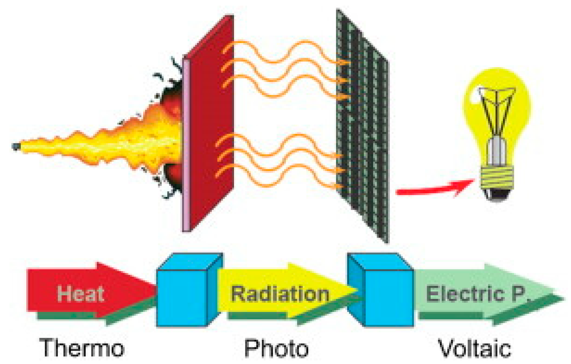
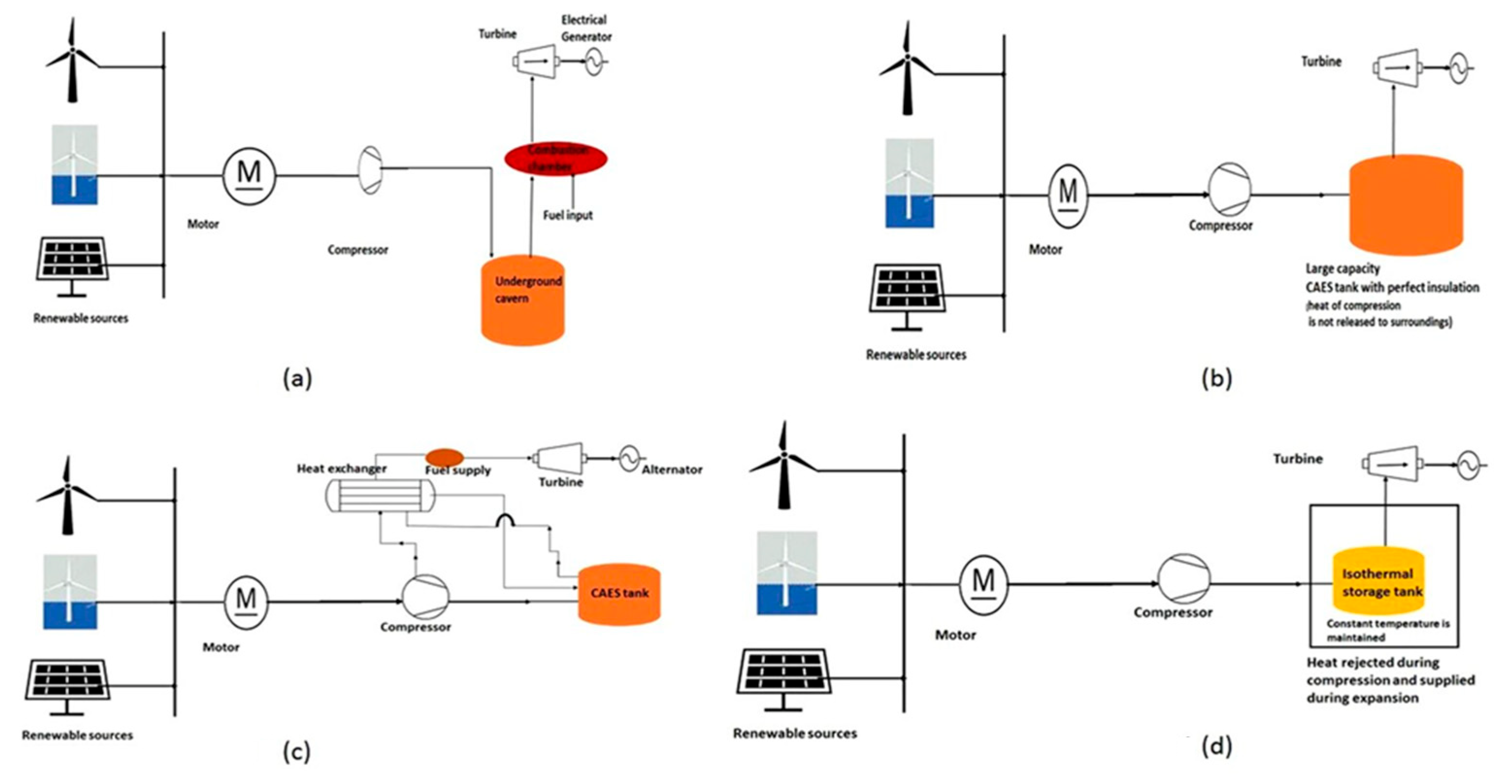
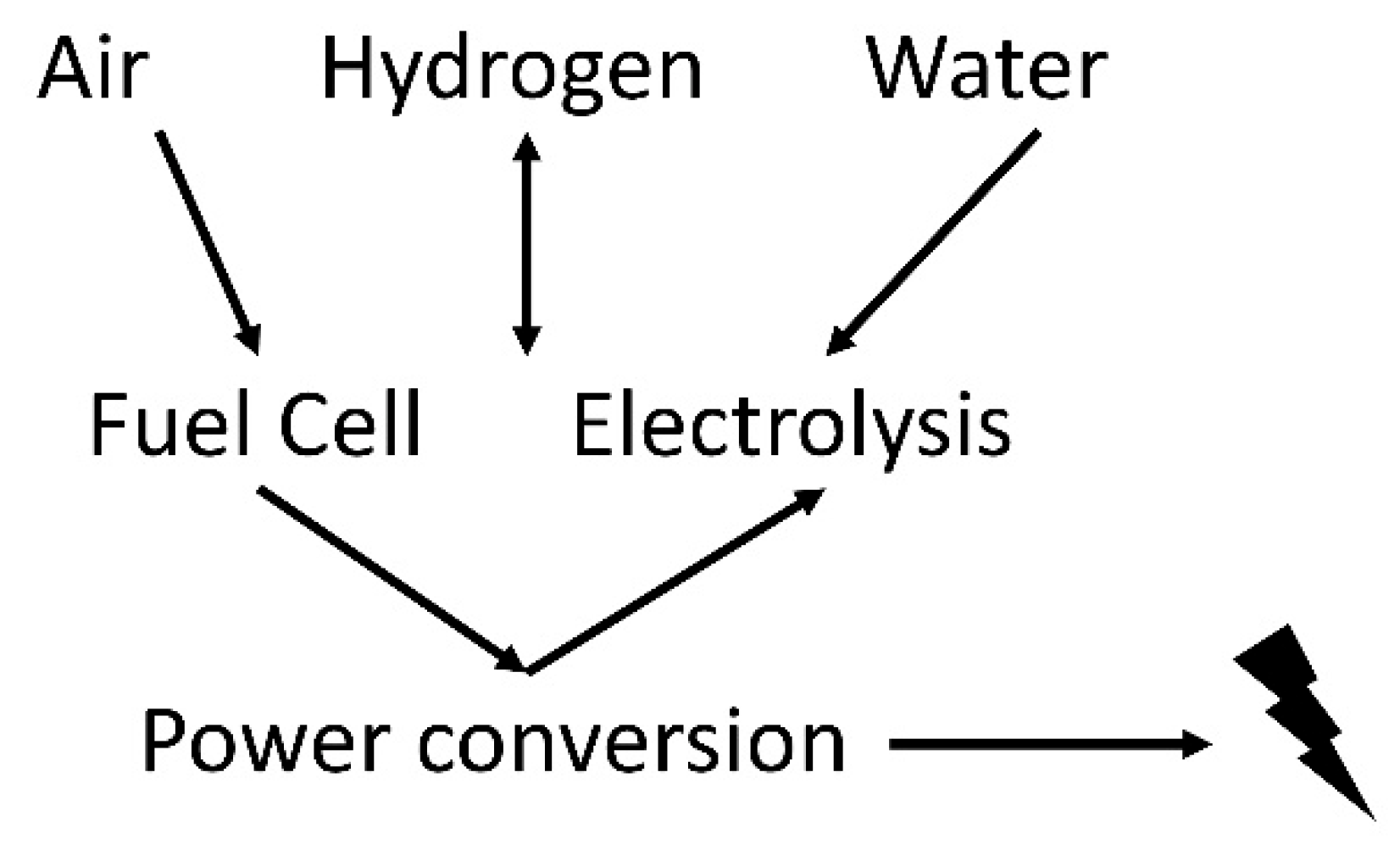
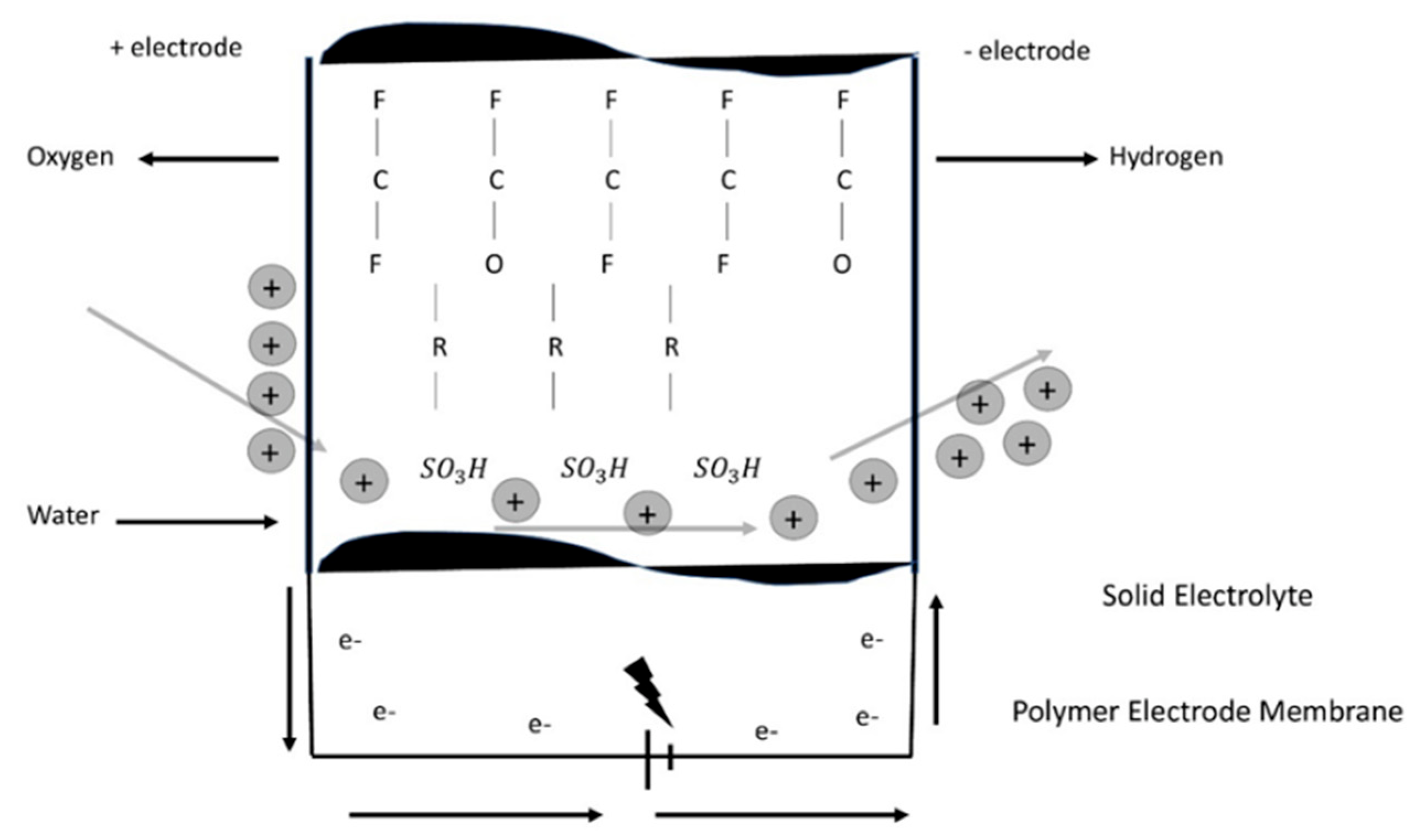
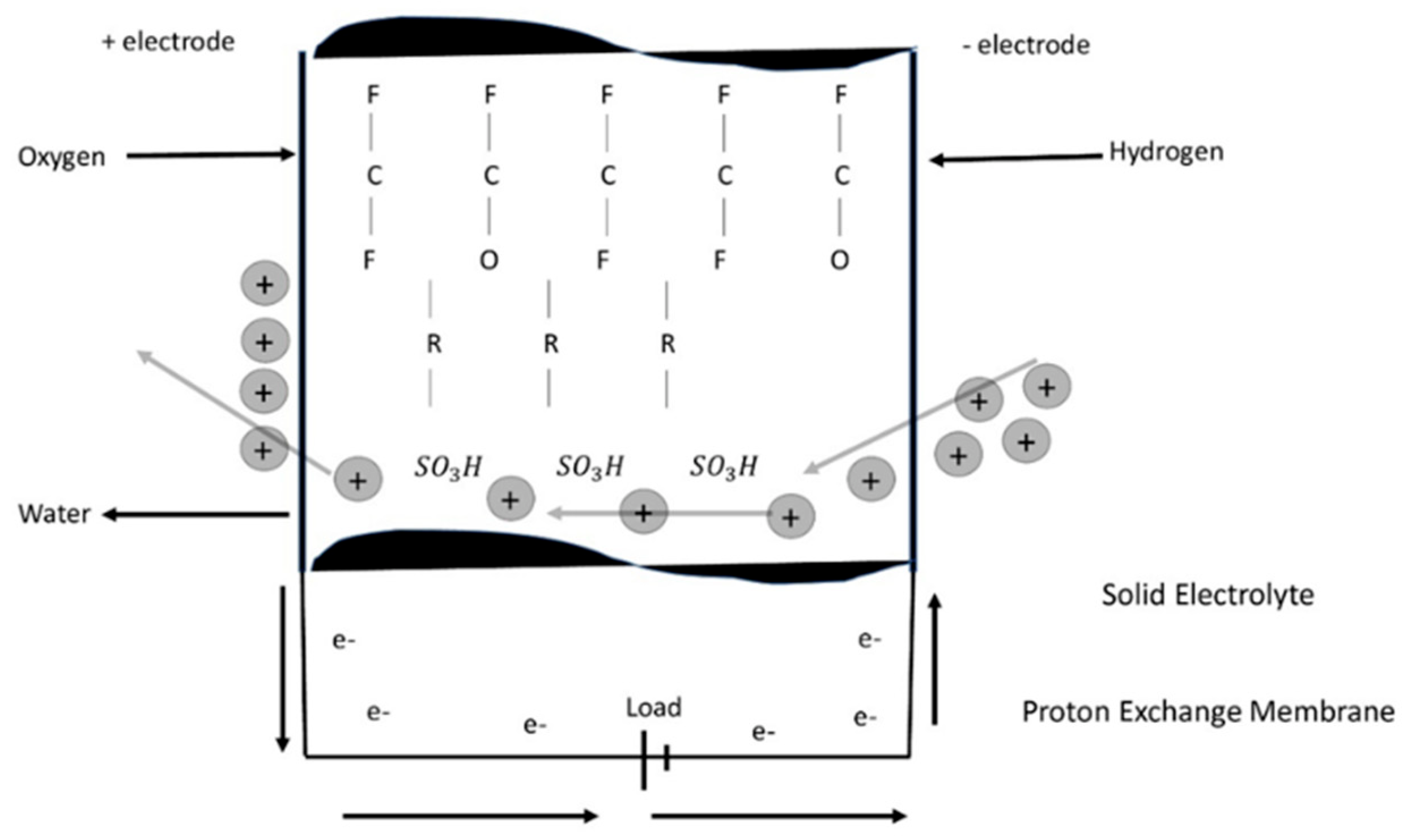
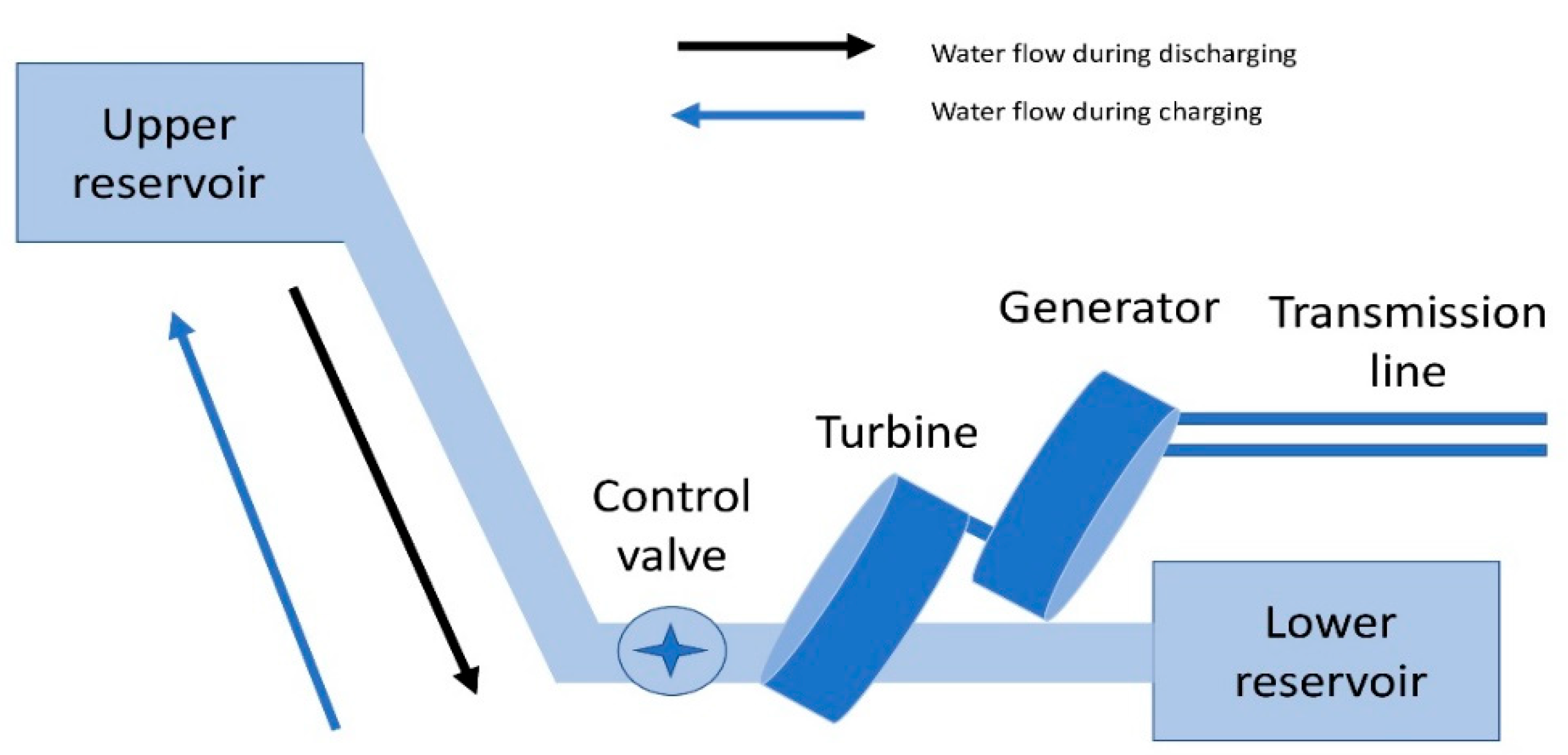
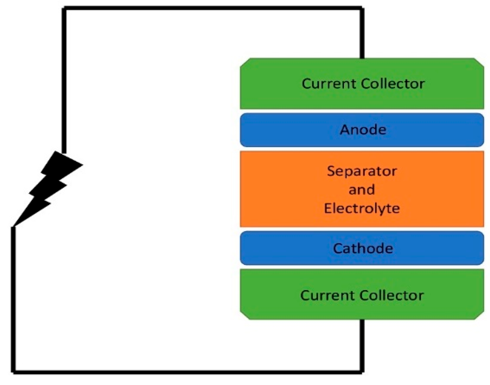
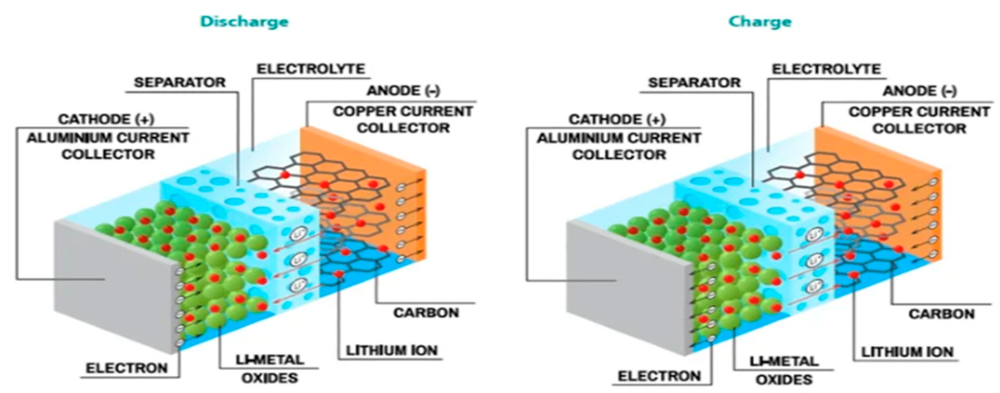
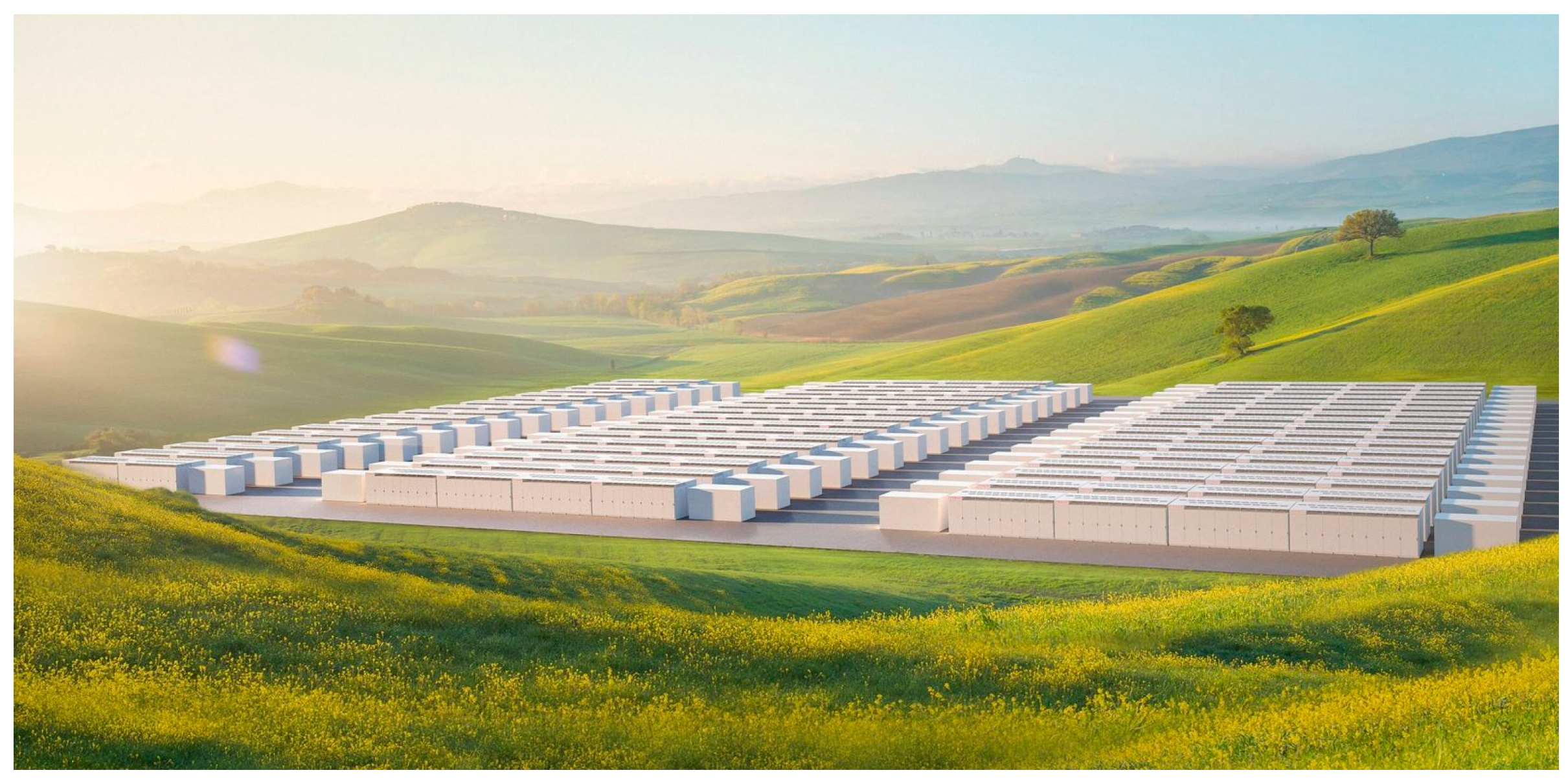
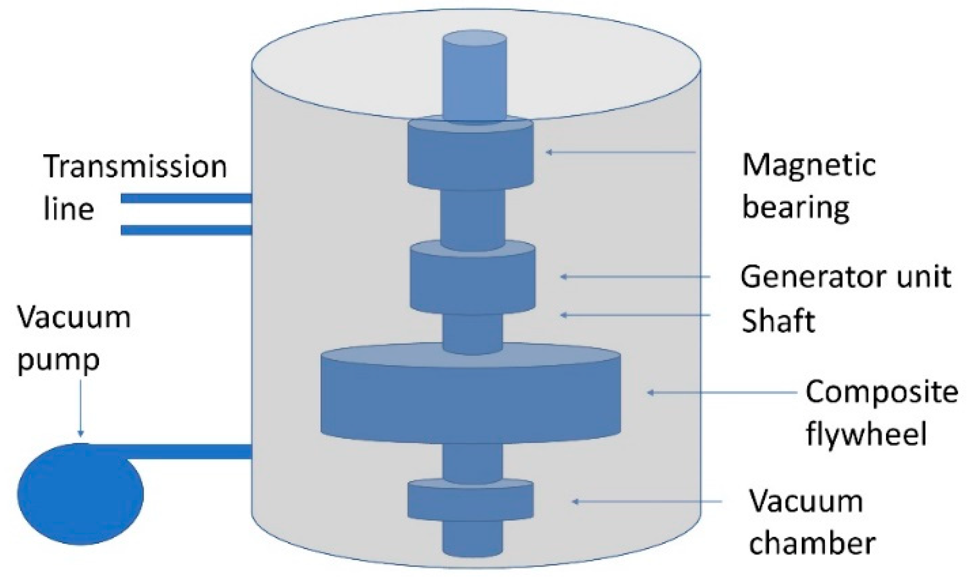
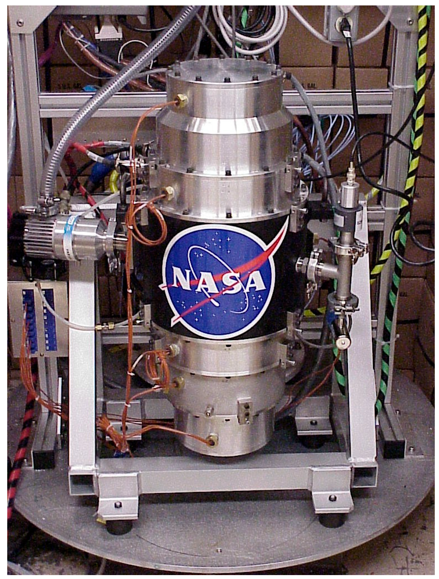
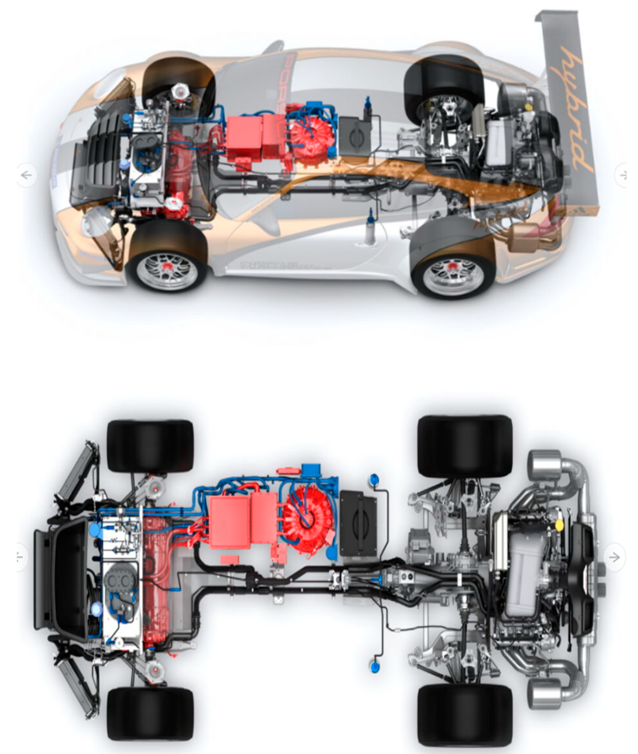
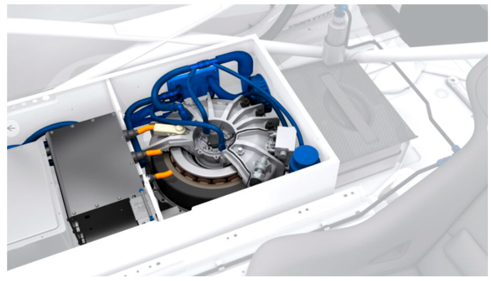
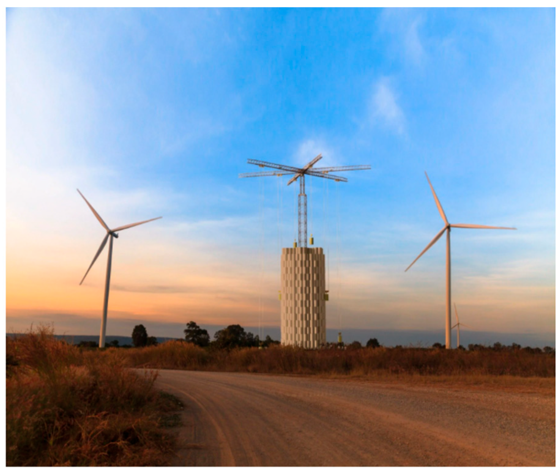
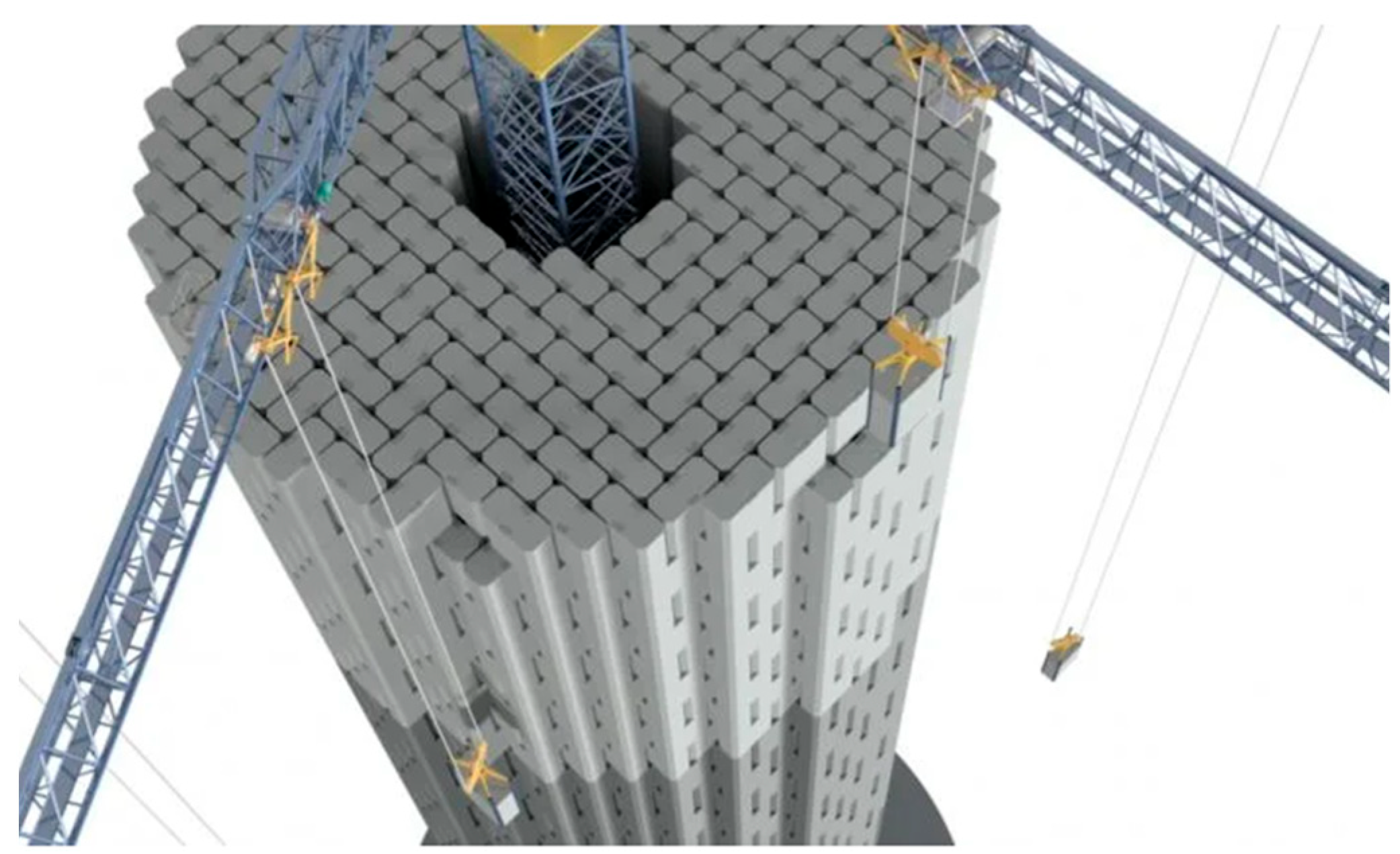
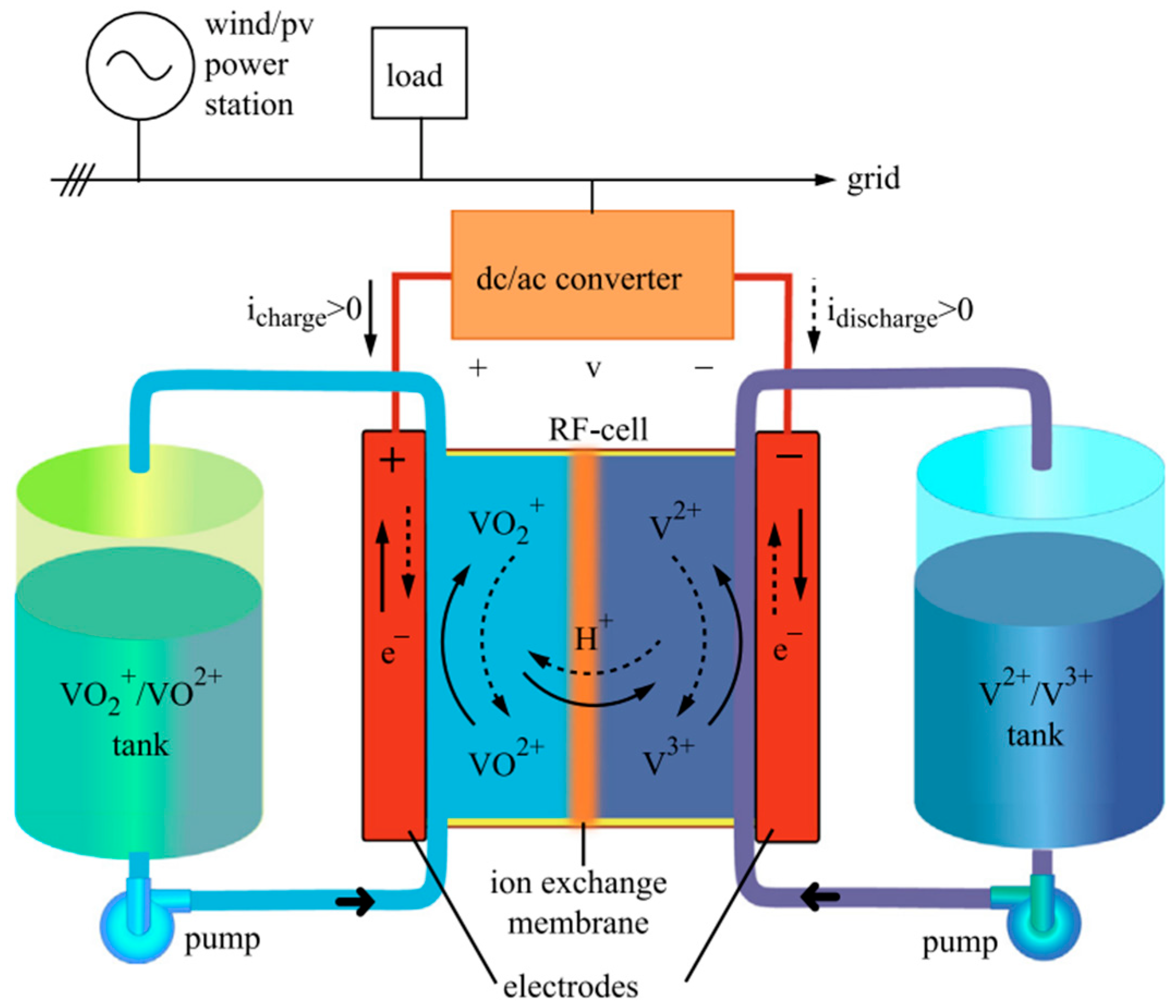
Table 1.
Global availability of renewable energy sources.
| Source of Energy | Global Energy Potential (in Trillion Watts) |
|---|---|
| Wind | 1700 |
| Wave | 2700 |
| Geothermal | 45 |
| Hydroelectric | 1900 |
| Tidal | 3700 |
| Solar (photovoltaic) | 6500 |
| Direct sunshine | 4600 |
Table 2.
Top global pumped hydro energy producers.
| Country | Capacity |
|---|---|
| China | 30,320 MW |
| Japan | 21,894 MW |
| United States | 19,140 MW |
| Germany | 5355 MW |
| India | 4786 MW |
| South Korea | 4700 MW |
| Italy | 3940 MW |
Table 3.
Top methanation producers worldwide.
| Supplier | Technology Employed |
|---|---|
| Air Liquide | Lurgi methanation |
| Haldor Topsoe | TREMP |
| Clariant and Foster Wheeler | Vesta |
| Johnson Matthey | HICOM |
| Linde | Linde isothermal reactor |
Table 4.
Top methane-producing plant names against their location.
| Plant Name | Location (Country) |
|---|---|
| GAYA | France |
| GOBIOGAS | Sweden |
| BioSNG | Austria |
| Great Syn Fuels Plant | USA |
| DemoSNG | Sweden |
| CPIProject | China |
| Keqi Project | China |
| POSCO Project | South Korea |
Table 5.
Top-rated capacity Li-ion energy storage systems worldwide.
| Project | Capacity | Location |
|---|---|---|
| Hornsdale Power | 150 MW | Australia |
| Stocking Pelham | 50 MW | Germany |
| Jardelund | 48 MW | United Kingdom |
| Minamisoma Substation | 40 MW | Japan |
| Nishi-Sendai Substation | 40 MW | Japan |
| Laurel AES | 32 MW | United States |
Publisher’s Note: MDPI stays neutral with regard to jurisdictional claims in published maps and institutional affiliations. |
© 2022 by the authors. Licensee MDPI, Basel, Switzerland. This article is an open access article distributed under the terms and conditions of the Creative Commons Attribution (CC BY) license (https://creativecommons.org/licenses/by/4.0/).
Share and Cite
MDPI and ACS Style
Sridhar, S.; Salkuti, S.R. Development and Future Scope of Renewable Energy and Energy Storage Systems. Smart Cities 2022, 5, 668-699. https://0-doi-org.brum.beds.ac.uk/10.3390/smartcities5020035
AMA Style
Sridhar S, Salkuti SR. Development and Future Scope of Renewable Energy and Energy Storage Systems. Smart Cities. 2022; 5(2):668-699. https://0-doi-org.brum.beds.ac.uk/10.3390/smartcities5020035
Chicago/Turabian StyleSridhar, Sushyanth, and Surender Reddy Salkuti. 2022. "Development and Future Scope of Renewable Energy and Energy Storage Systems" Smart Cities 5, no. 2: 668-699. https://0-doi-org.brum.beds.ac.uk/10.3390/smartcities5020035