1. Introduction
In current physics, the contribution of vacuum energy to the stress–energy tensor in the Einstein equations [
1] is still an open question. Despite long and deep investigations, there is not yet a convincing explanation of the fact that the enormous amount of energy attributed by quantum mechanics to mechanics does not significantly determine the geometry of our universe [
2,
3,
4,
5,
6,
7,
8] and, moreover, it is still questioned how and whether the vacuum fluctuations do interact with gravity [
9,
10,
11,
12,
13]. Theoretical results can be controversial even in the usual approach of quantum field theory in weak gravitational field [
14] so that, even if the general expectation is that vacuum energy does gravitate, a deeper understanding is generally required and experiments are considered [
15].
From an experimental point of view, it is important to note that in the recent past the scientific community focused on the possibility of verifying or discarding the various hypotheses by measuring the effects of the gravitational field on a Casimir cavity [
16,
17,
18,
19,
20,
21], in particular by performing a weighing measurement on a rigid Casimir cavity [
22,
23,
24].
The expected force that on Earth the gravitational field can exert on a suitable realized Casimir cavity is in any case very small but it could be detectable if a suitable modulation of the force and an extremely sensitive apparatus were used. In principle, energy modulation in a Casimir cavity could be obtained by radiating semi-conductive plates with light to move electrons from the valence to conductive band, resulting in a modulation of plates reflectivity and thus of the vacuum energy. Such kind of modulations has been proved to be efficient when measuring a change of the Casimir force among moving plates [
25,
26,
27], but unfortunately it would be useless for the weight measurement in a rigid cavity because the change of the Casimir energy would be several orders of magnitude lower than the electromagnetic energy deposited through the light. A possible way to change the plates reflectivity using an amount of energy comparable with Casimir variation is by using a superconductive transition. In particular, type I superconductors can be used to test the modulation of the Casimir energy in a suitable cavity formed by superconductive plates separated by a dielectric [
28,
29,
30,
31]. Unfortunately, in this case, even if the behavior of the superconductor were very well known, the absolute value of the energy variation would be too small to be weighed. On the contrary, if type II layered superconductors were considered, the absolute energy variation could be compatible with a weigh measurement. Type II layered superconductors, such as the Yttrium Barium Copper Oxide (YBCO) or the Bismuth Strontium Calcium Copper Oxide (BiSCCO), are formed by planes that undergo a superconductive transition separated by nanometric layers that remain dielectric. As first noticed by Kempf, they are naturally rigid Casimir cavities, so that in these samples not only the absolute energy variation could be compatible with a weight measurement, but also the relative contribution of Casimir energy is expected to be high [
32,
33,
34]. On this basis, we recently started an experiment, called Archimedes, to measure the weight variation of a type II superconductive sample undergoing a superconductive transition in order to evaluate the force exerted by the gravitational field on a Casimir cavity.
The measurement must be performed with an extremely sensitive balance working at cryogenic temperature, modulating the superconductive transition at very low frequencies, about tens of mHz, and operating in a seismically quiet site, in order not to be limited by seismic noise. In the following, we describe the main issues of the experiment, recalling the magnitude of the expected signal, explaining in particular the main choices and studies of the experimental apparatus and the first results on a prototype of beam balance. Details on the mechanical, optical, and control loop are presented to show the most interesting results. The other cornerstone of the experiment, the cryogenic system, is also presented: the final design is shown, discussing the main items. Considering that the measurement greatly benefits from being performed in quiet seismic environments, we briefly describe the site chosen for the measurement: the underground laboratory named Sardinia Gravitation Laboratory (SAR-GRAV), presently under construction in Lula (Sardinia, Italy). Finally, the path toward the final measurement is presented.
Interestingly, such an apparatus turns out to be of interest also for low mass dark matter search [
35]. More generally, extremely sensitive beam balances can be used as absolute rotation sensors, which are becoming now relevant instruments for Newtonian Noise subtraction in gravitational wave detectors [
36,
37]. The balance prototype that is discussed is in fact presently acquiring seismic data at the Virgo site during its scientific Run O3.
2. General Scheme of the Experiment
In various papers [
23,
24], the force exerted by the gravitational field on a rigid Casimir cavity at rest on Earth has been calculated: it is directed upward and it is equal to:
where
is the (negative) Casimir energy,
c is the speed of light, and
is the Earth gravitational acceleration. The theoretical calculation of this force assumes that the pressure of the vacuum fluctuation also follows the equivalence principle, thus the Archimedes measurement is actually a zero measurement of the red-shifting of vacuum pressure in gravitational field [
16,
23]. The force is extremely tiny and thus the measurement must be performed by modulating the effect.
The method proposed to modulate the Casimir energy in a rigid cavity is by modulating the plates reflectivity with a superconducting transition: when the plates are superconducting they are more reflective and the vacuum is better expelled from the cavity, resulting in a lowering of the energy and, if it gravitates, of the weight [
23,
31]. If the Casimir cavity is composed of type I superconductors plates, for temperatures lower but not far from the transition temperature, the contribution of the vacuum energy variation to the total condensation energy is comparable with the contribution of the variation of the chemical binding energy [
28,
29,
30,
31]. Under these conditions, once the weight measurement is performed, it would be not an issue to recover the contribution of the vacuum energy to the weight.
Unfortunately, as already stated, the absolute value of energy variation is too small to be weighed. The superconductors, instead, will be of a layered type II, such as YBCO or BiSCCO: layered superconductors are a natural stack of partially-reflecting, coupled Casimir cavities, whose condensation energy is much higher with respect to type one superconductors, and is expected to be directly influenced by vacuum fluctuations, as firstly noticed by Kempf [
32]. The percentage of condensation energy that is due to the Casimir energy is still under evaluation. In the most optimistic case, it is almost the totality [
32]; further theoretical and experimental studies are not in disagreement with Kempf’s order of magnitude estimation of the effect [
33,
34]. It is important to note that all calculations to estimate the vacuum fluctuations contribution to the superconductor condensation energy have been performed until now within a macroscopic approximation. Although the results obtained with this approach are not in contradiction with experimental tests, they cannot be considered yet completely satisfactory. A microscopic scattering approach which includes virtual scattering of photons within the layers with Cooper pair breaking and recombination can account for the change of the electromagnetic spectrum, according to the Anderson–Higgs mechanism [
38] and the change of Casimir energy with respect to the normal metal phase, and it is presently under development in our group.
The actual weight measurement will have an accuracy of a few percent, thus it will be possible to ascertain the interaction of gravitational field with vacuum fluctuations even if the contribution were proven to be of this order of magnitude.
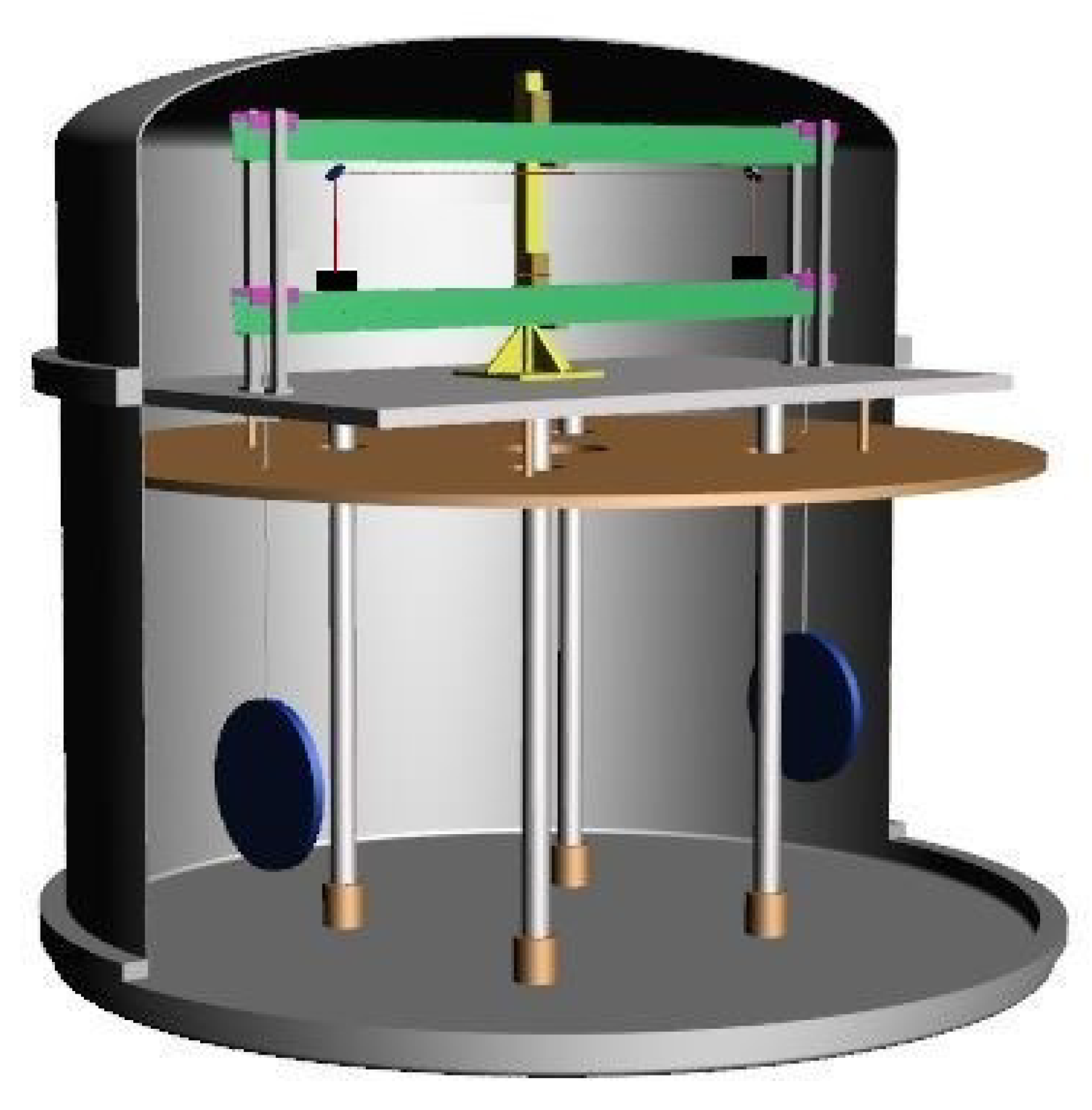
The proposed scheme of the measurement is given in
Figure 1: two discs of layered superconductor are suspended to the arm of the balance. The two discs are made of the same material but with different doping and oxygen content. The arm is in aluminum to maintain low weight and momentum of inertia. The length of the arm is 1.4 m and it is suspended on low dissipative joints. The temperature modulation is the same in the two discs but only one undergoes the superconductive transition, thanks to the different oxygen content [
39,
40]: in this way, the phonon energy variation, which is equal on both samples, is cancelled out (does not give a signal on the balance).
The superconductive samples are 3 mm thick and have a radius of 0.15 m. Therefore, the expected amplitude of the force modulation is
N [
23]. The expected integration time is
s (about two months). To compare the signal with noises, usually expressed in terms of amplitude spectral density, and taking into account the two months of integration time, the equivalent amplitude spectral density of the torque signal is
.
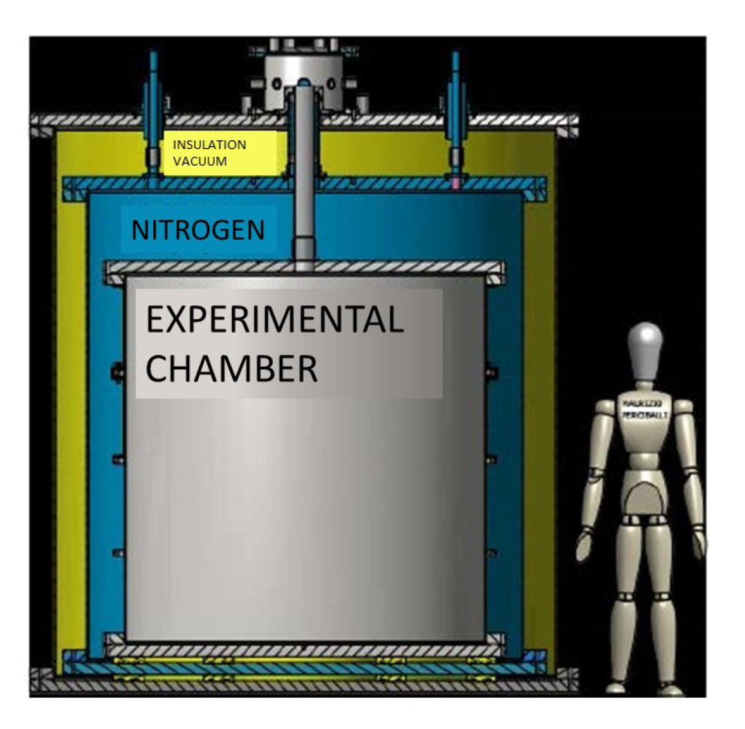
3. The Cryogenic System
The Archimedes experiment is designed to work at a temperature of about 90 K. To reach this goal, a particular cryostat, working with liquid nitrogen, has been designed and its construction is expected to be finished in 2020. The cryostat is given in
Figure 2.
The chamber where the experiment is housed can be completely covered with liquid nitrogen. However, even when the nitrogen level falls below the upper chamber flange, an aluminum screen attached to the steel chamber ensures a good thermal uniformity. The volume of liquid nitrogen in the tank is about 4000 L. Considering a typical thermal input of about 2 , the evaporation time of nitrogen will be about five months. The cryostat is equipped with a level probe for liquid nitrogen, a series of thermometers, and a heater of several kW located at the bottom of the experimental chamber and soaked in cryogenic liquid. In this way, it is possible to force the evaporation of the liquid nitrogen and reduce the time needed to access the experiment when necessary, as could be required in the first period of commissioning. The cryostat is designed in such a way that the experimental chamber can also be used as a simple vacuum chamber to operate the experiment at room temperature, as requested in the first period. For this purpose, all flanges have the possibility of being closed with Viton or indium gaskets. The upper socket, from which all the electrical and optical connections will enter the inner experimental zone, is designed in such a way that can be used both at cryogenic temperature and at room temperature, when, in the first period, only the inner part of the cryostat will be mounted.
The idea behind the design of the cryostat and therefore the experimental chamber is to provide a rigid platform, the lower flange of the chamber, over which to build the experiment. Once the inner part of the experiment is assembled and pre-commissioned, the cylinder of the cryostat will be positioned. Finally, the upper flange will be installed. In this way, the cryostat will only minimally perturb the rest of the experimental apparatus during its assembly. This setup will allow the needed tests and commissioning at room temperature. When the cooling down will be necessary, the two external cylinders will be installed and the upper socket connected to the outermost chamber.
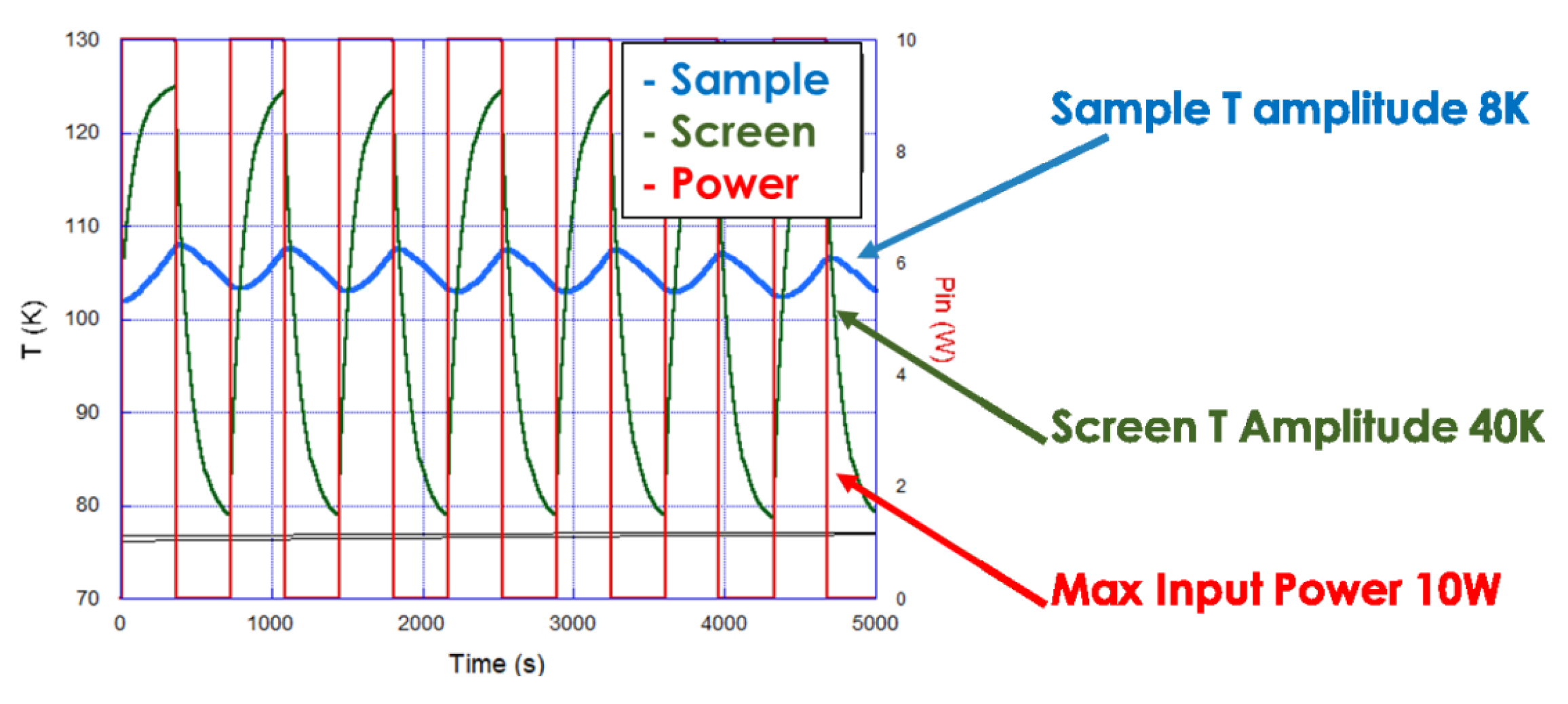
Temperature Actuators
Temperature modulation is needed to force the superconductor to enter and exit the superconducting state, in order to obtain the desired modulation of the Casimir energy. The temperature must be modulated around the sample transition temperature with amplitude of a few K. Thermal exchange must happen without direct mechanical contact with the sample, since this would imply uncontrolled forces on the sample and destroy the force measurement. The only allowed solution is to have the sample in thermal equilibrium with the radiation bath. The temperature is regulated by the surrounding screen, heated from outside. The modulation frequency depends on the thermal properties of the sample and of the surrounding screen. Accurate simulation and geometry definition is necessary to obtain an efficient modulation. In this way, the cavity (the multi-cavity formed by the multi-layer superconductor) exchanges energy only with the radiation and the vacuum, and the radiation is used to confine and expel the vacuum from the cavity. The only variation of the sample is its transition from normal to superconductor state, and vice versa. The weight variation is the condensation energy weight, which in turn is the weight of the vacuum energy confined/expelled from the cavity. Several simulations have been carried out with the help of finite elements analysis, with transition temperatures in the range 90–130 K. The sample is suspended on the arm balance with a low conductivity thin wire and it is completely surrounded by the thermal screen. The temperature of the screen, made of copper, is modulated by a laser. The laser solution is preferred since it is simple and safer compared with other solutions, such as heating with electrical currents, which could interact with the sample. The screen is attached to the cryostat. A typical sample temperature modulation curve is given in
Figure 3. It is evident that an amplitude of a few degrees is obtained at the frequency of 5 mHz, compatible with the requirements.
4. The Balance Prototype
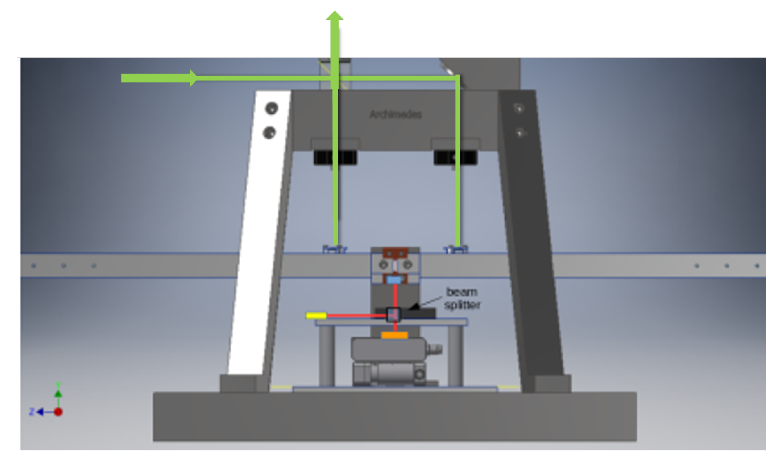
To test the most critical points in the realization of this extremely sensitive device, a balance prototype, working at room temperature, was realized and tested. The balance prototype shares with the final one several mechanical parts and the sensing scheme. The arm length prototype is 0.5 m long, with respect to 1.4 m of that in the final balance. In the prototype, the reference arm is not suspended. The optical read-out of the balance prototype is very similar to the final one, being composed by an optical lever and a Michelson interferometer. As shown in
Figure 4, the arms of the Michelson interferometer have different length. Other optical configurations, such as a Mach–Zehnder, would warrant an easy design with equal arm-lengths, but the Michelson interferometer was chosen since its optics on the measurement arm are simple mirrors impinged at 90 degrees. This configuration minimizes spurious couplings with other degrees of freedom of the balance arm. It is presently under study an equalization of the two arm-lengths with optics added on the balance reference arm. The optical lever is a high range sensor used in feedback mode to bring the interferometer in the linear regime. In the configuration with the loop closed on the optical lever, the balance can work even in the presence of high seismic noise, recover from earthquakes, and operate for quite long time, of the order of weeks, without need of external actions. The apparatus has been used in this configuration since the seismic noise in the laboratory is quite high. The balance prototype scheme is given in
Figure 4. The light path in the Michelson interferometer is shown in green. The light path of the optical lever is shown in red: the light is first reflected on the back of the arm, and then transmitted by the beam splitter to a quadrant photodiode. In this configuration, the majority of the light is not used, being both partially transmitted when impinges the first time on the beam splitter and partially back-reflected when impinges on the beam splitter for the second time. This is not a problem since we are not limited by shot noise and, moreover, in the future, the light transmitted at the first impingement can be used for noise subtraction, if necessary.
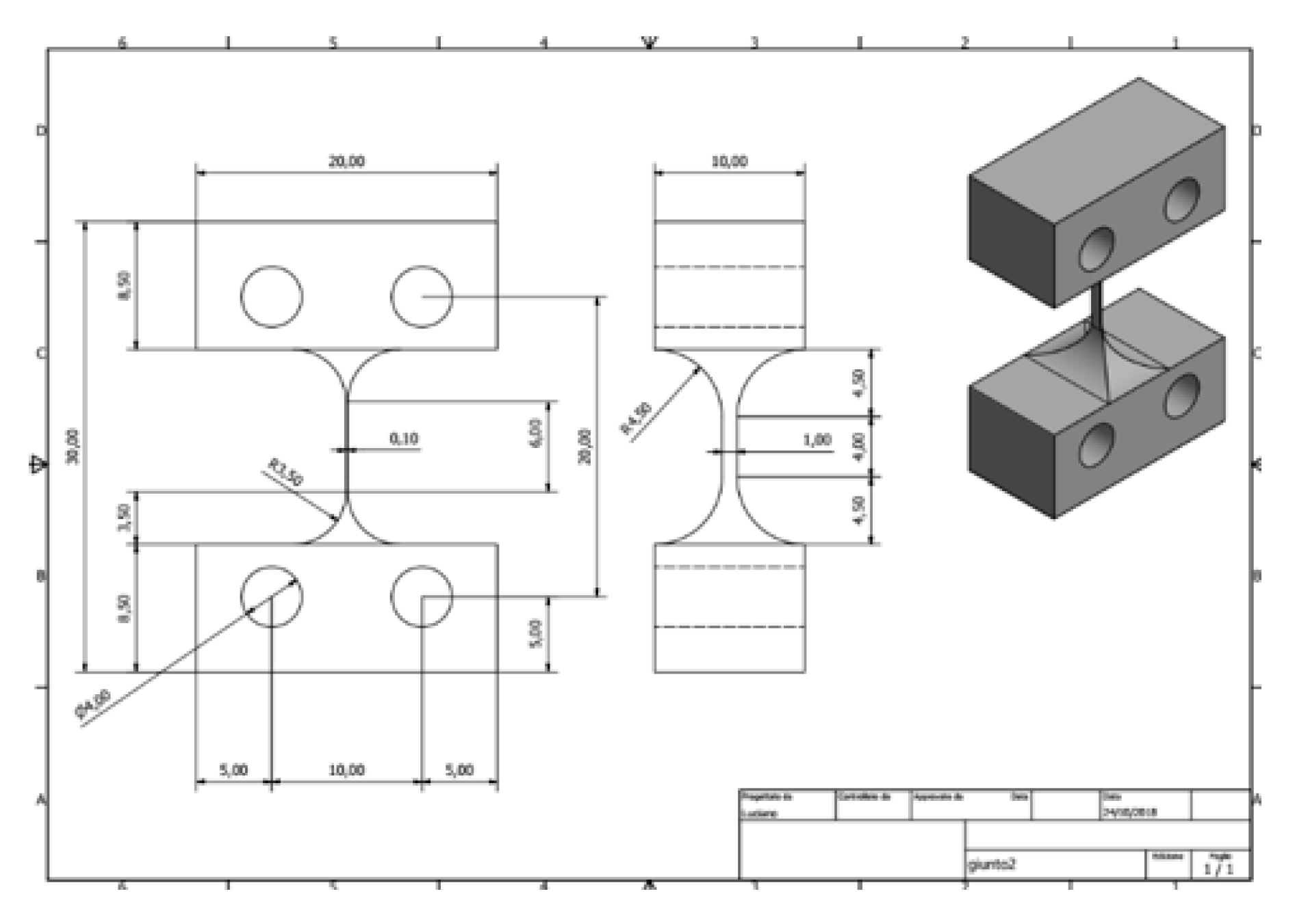
In the mechanics, particularly important is the design of the joints from which the balance arm is suspended: they contribute to the restoring torque and directly affect the sensitivity. They must be sufficiently soft to obtain readable signals and keeping the resonance frequency in the tens of mHz frequency region. The design implemented is inspired by the joints used in the rotational sensor of Venkateswara et al. [
41]. In that case, the stiffness was lowered thanks to a very thin thickness, as small as 0.02 mm. In our case, we designed a bundle with a thickness of 0.1 mm, height of 6 mm, and width of 0.5 mm. Our design made easier the joint machining, and hence is cheaper. The joints design is given in
Figure 5.
The first test of the balance was performed in our laboratory in Naples. Unfortunately, in the laboratory, the seismic noise is very high even at high frequencies, above 10 Hz, so that the interferometer signal is extremely noisy even at high frequencies. The best way to run the apparatus in these conditions is to close the feedback loop on the optical lever, without closing the control loop with the interferometer, and to recover the interferometer sensitivity by subtracting the optical lever noise with an off-line analysis. The actuation system is composed of electrostatic actuators as typically used in the control of torsion pendulums [
42,
43]. In our case, the actuators are four metallic plates located at the sides of the balance beam. The balance beam is grounded while the actuators are driven by a DC voltage supplier, which can reach the maximum voltage of 2000 V. The actuator torque is quadratic in the applied voltage with coupling factor
. The maximum torque is
. The control signal is linearized by operating the square root of the error signal before sending it to the actuators. Such a kind of control is extremely useful to test the validity of control loops, to test the long term behavior of the balance, and to define a noise budget for future commissioning when the balance will be operated in a quiet site. The control scheme is given in
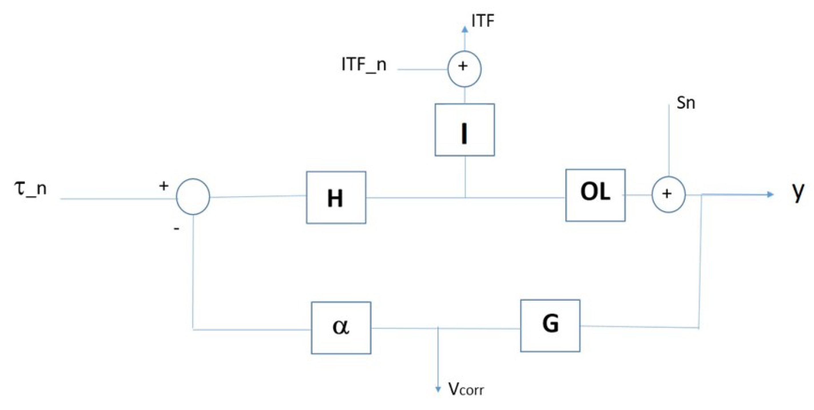
Figure 6.
The optical lever has a relatively modest sensitivity since its role is to lead the system to working point and then leave the loop closed on the error signal of the interferometer. However, as mentioned above, the high frequency seismic noise prevents closing the loop on the interferometric signal. Without complicating the system and in view of using the instrument in the much better conditions of the Sos-Enattos site, a check of the balance performance can be done anyway. The starting point is the consideration that at very low frequencies, below 100 mHz, the sensitivity of the interferometer is better than the optical lever even under these conditions. Therefore, even if the signal is not compatible with the closing of the loop, it can be used off-line as a noise subtraction. To explain the subtraction procedure, it is useful to illustrate the loop diagram (
Figure 6). The signal read by the optical lever is
y, the one read from the interferometer is
, and the correction voltage sent to the amplifiers is
. The
H function is the plant (measured in rad/Nm),
I is the sensitivity of the interferometer (measured in V/rad),
is the sensitivity of the optical lever (measured in V/rad),
G is the control filter (dimensionless), and
is the function (which is a constant in this case) describing the amplifiers and actuators (Nm/V).
indicates the equivalent external torque noise and
and
indicate the read-out noises of the interferometer and of the optical lever, respectively. Since the system is linear, for sake of simplicity, the outputs
y,
, and
can be written separately as linear functions of the input signals
and
. In particular, for
, we obtain:
, , , and, as a function of :
, ,
The signal of interest is called
and it is defined as:
. It cancels the noise from the optical lever using the interferometer signal. This effect is evident by writing it explicitly:
Notice that the read-out noise of the interferometer is added as a last term since it does not enter the loop. In the out signal, the contribution of the sensing noise of the optical lever is cancelled and the signal is a measure of the torque acting on the balance and the measurement noise is determined by the interferometer sensitivity:
This signal can be better understood if we consider the high gain regime, typical of the low frequency region, where the weight measurement will be performed. If the signal of the optical lever is dominated by the external torque, signal is suppressed, the whole signal is found in , and from their difference is recovered, being dominated by . Conversely, if the signal of the optical lever is dominated by the lever noise, the arm is tilted by the control loop to cancel the optical lever error signal, and reads exactly the movement generated by . In this case, the subtraction of these signals cancels the lever noise. As stated above, this subtraction is useful only in conditions of high seismic noise. In the quiet conditions at Sos-Enattos, the optical lever will be used only to bring the interferometer to the working point, and then the loop error signal will become the interferometer signal.
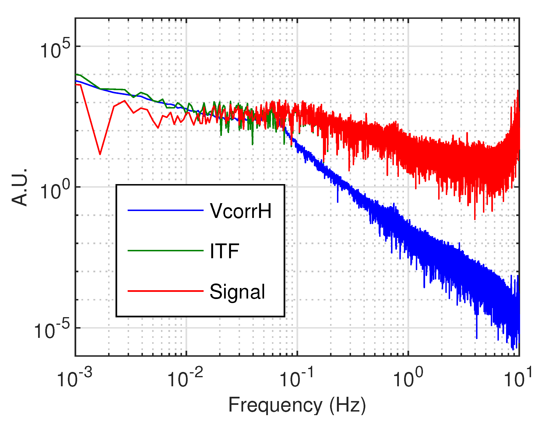
Preliminary results are given in
Figure 7 and
Figure 8.
Figure 7 shows the tilt signals. It can be noticed how the interferometer signal and the correction
are similar at low frequencies. In this condition, the interferometer is actually reading the tilt of the arm forced by the loop to cancel the error signal of the optical lever, dominated by the optical lever read-out noise, and the combination of the signals as previously described is expected to be effective.
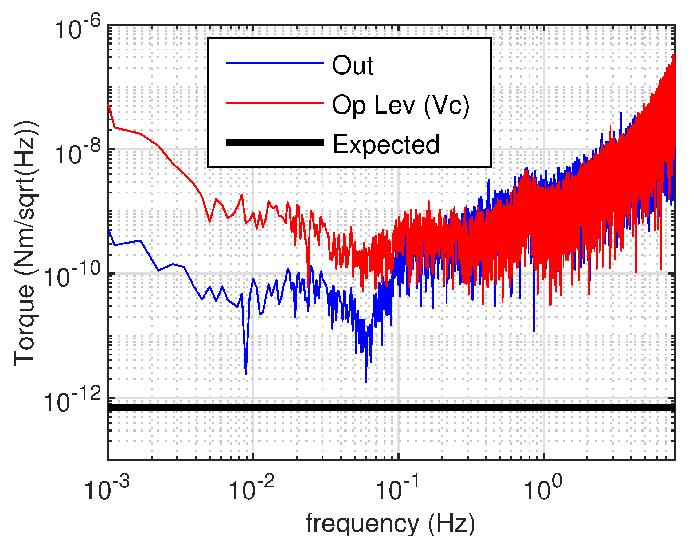
Figure 8 shows the result of the subtraction. The low-frequency signal is efficiently subtracted, being in the high gain regime. In the high-frequency region, where the gain of the loop is lower than unity, as expected, no gain is observed in the combined signal. The main outcome of these results is the demonstration of the effectiveness of the mechanical, sensing, and actuating systems, of the robustness of the control loop and of the effectiveness of the noise subtraction techniques thanks to a very good knowledge of the system. All these features are very promising in view of the installation of the balance in the seismically quiet Sos-Enattos site. However, the resulting sensitivity is also quite interesting, since in the frequency region lower than 100 mHz, down a few mHz, the torque sensitivity is comparable with the best in the world [
41], reaching a few times
.
5. Discussion
Working in a high seismic noise environment is problematic for the balance. High seismicity prevents easily closing the loop on the interferometer error signal, forcing to maintain the error signal on the more noisy optical lever. Our results demonstrate that the balance can indeed be controlled with good efficiency and good sensitivity, therefore they are very promising. Nonetheless, the optimal configuration for the balance is to work in a quiet seismic environment.
In Italy, after long investigations, an extremely quiet site has been individuated: the Sos-Enattos mine, on Sardinia Island. In this region, the seismic noise, also at frequencies lower than 0.1 Hz, lies very near the New Low Noise Model (NLNM) from Peterson [
44]. This site is so quiet that it has been proposed as a strong candidate to host the European underground third generation gravitational wave detector, named Einstein Telescope (ET) [
45,
46]. The mine is preserved by the I.G.E.A. s.p.a. company and is located near the village of Lula in Sardinia. It is a former mine of schist rocks composed by sphalerite ([Zn,Fe]S) and galena (PbS). While waiting for the final choice of the site for the ET, several Italian institutions decided to build an underground laboratory SAR-GRAV, devoted to hosting experiments on gravitation or seismology that need particularly quiet seismic conditions. At the surface, a laboratory for medium size experiments (e.g., Archimedes) is already available. The underground laboratory is presently under construction, the designed cavern being about 200
area with a 10 m height.
Archimedes installation on site will start on February 2020 and the first period of commissioning and testing of the apparatus will be performed at the surface and at room temperature. The sensitivity of the balance, already promising, is expected to greatly benefit from working in such good seismic conditions (especially if compared with the really noisy conditions of our laboratory in Naples), and, indeed, it is expected to gain, during two years of commissioning, the two orders of magnitude which separate the present sensitivity from the final one.

 ,
, 


