1. Introduction
All devices and materials used in environments with high radiation levels must undergo screening processes in order to test the working limits in all operating conditions. Often, such extreme environments do not allow for the replacement and/or maintenance of the instrumentation, meaning that the devices must satisfy very strict demands in terms of reliability and radiation tolerance. Technical specifications for radiation hardness assurance (RHA) tests are defined by international standard protocols [
1,
2].
In particular, the European Space Agency (ESA) has issued specifications for the (1) total ionizing dose (TID) [
3], performed mainly with
60Co gamma sources and electron accelerators; (2) displacement damage dose (DDD) [
4], performed with proton and neutron sources; and (3) single event effects (SEE) [
5], performed with heavy ions, and proton and neutron sources.
RHA tests are intended to experimentally simulate the radiation environment at which the devices are meant to be exposed to during their operational life. The purpose of RHA tests is to detect any malfunctioning due to radiation exposure and to ensure that the device performances are consistent with the specifications after exposure to a given dose. The success of the RHA tests depends on many factors, including the definition of the exact radiation environment and its accurate reproduction, thorough dose monitoring, the selection of parts and components, and the design of the experimental test. The experimental simulation of the radiation environment is a crucial and challenging task. For space applications, devices must work in the presence of a complex natural radiation environment mainly composed of electrons and protons trapped by planetary magnetic fields, protons, and heavier nuclei produced both in energetic solar events and from a galactic and extragalactic origin [
6]. The space environment can be simulated by means of experiments at facilities with particle accelerators and radiation sources. As the damage induced on the devices is also dependent on the duration of the exposure, time is another important parameter to be considered during the test. The whole operational life of a device can be several years. As a result, the tests are usually performed with an acceleration factor by using intense radiation fields to simulate the total radiation fluence in a short time. The accurate estimation of the radiation dose at which a device is exposed to during its operation is crucial for the definition of its operational limits. Accurate dose measurements are the most important aspect to derive reliable predictions of the radiation damage. On the one hand, the measurement should perturbate the radiation field as little as possible; on the other hand, the ideal scenario is to have a continuous measurement of the dose imparted to the device and the relative response. For these reasons, the full characterization of the radiation effects on the devices would require monitoring the performance of the irradiated devices by knowing any change in the radiation field. The real-time monitoring of the device under test (DUT), as well as of the radiation field, is fundamental, for example, for the electronic components to be used in satellites and spacecrafts. In this case, it is not only essential to know the breakdown threshold of the device, but it is also important to be able to reconstruct the probability of a malfunction after a given radiation dose below the breaking point.
Dose monitoring represents a crucial issue also in high energy physics experiments with large accelerators. In such experimental environments, there are mixed radiation fields with a complex spatial distribution, which depends on the geometry of the beam and of the collimators. In addition, these radiation fields can vary in intensity as a result of temporary beams losses, as well as of any variation in the beam conditions. Knowledge of the accumulated dose near the critical components of the apparatus is very important. In fact, most of these components are not accessible during beam operations, but only during a dedicated time window (beam shutdown). If the doses reach the critical level for a given component, this could be replaced during beam shutdown.
Usually, beam monitoring for RHA tests at particle accelerators is performed with parallel grid avalanche counters (PGACs) or ionization chambers. However, these instruments can also not be suited and/or perturbative for high linear energy transfer (LET) irradiations and/or for compact geometries of the experimental setup.
For in-air irradiation, for example, it is crucial to minimize the distance between the extraction window and the DUT to avoid beam energy loss. In such situations, large size gas detectors are not the optimal choice.
In this paper, an innovative dosimeter for real-time dose monitoring in RHA tests is proposed. It is based on a new radiochromic film (RCF) spectroscopic reading method that was recently developed [
7,
8,
9,
10,
11,
12,
13,
14,
15]. This new dosimeter allows for correlating in real-time the radiation dose at which the device is exposed to with the device performance. To demonstrate the dosimeter operation in relevant environments for the RHA, the dosimeter was exposed to different doses from three radiation fields, namely
90Sr/
90Y beta rays, electrons, and protons.
2. Materials and Methods
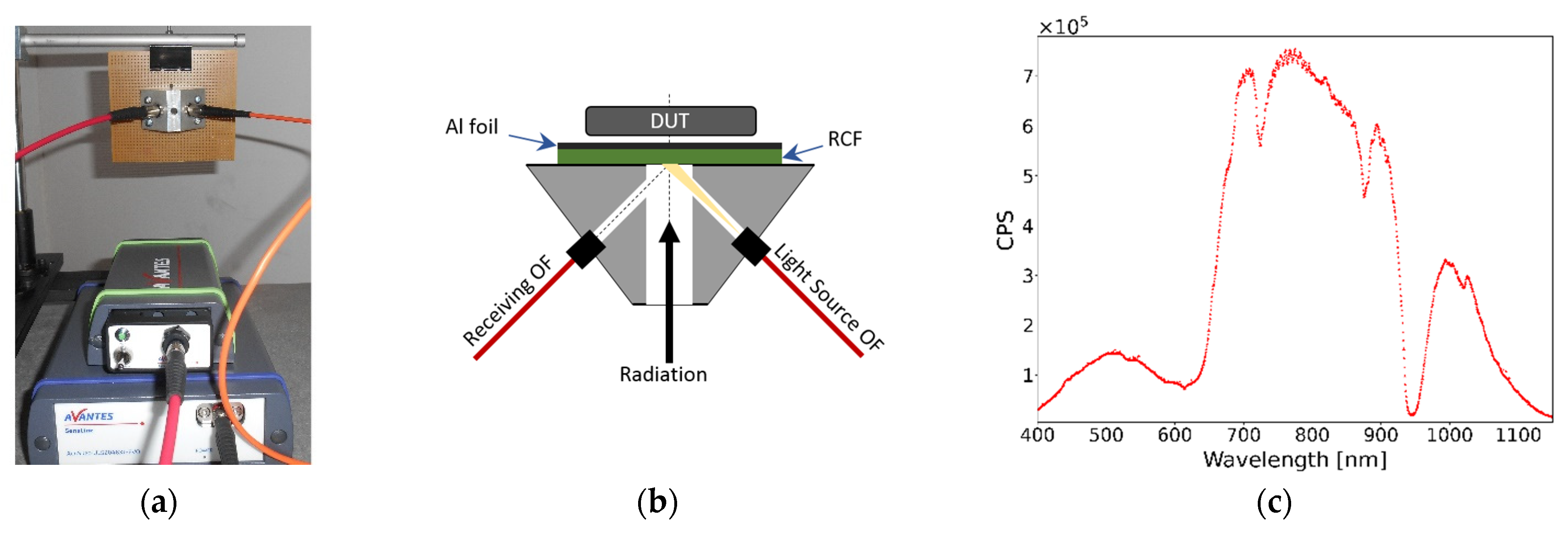
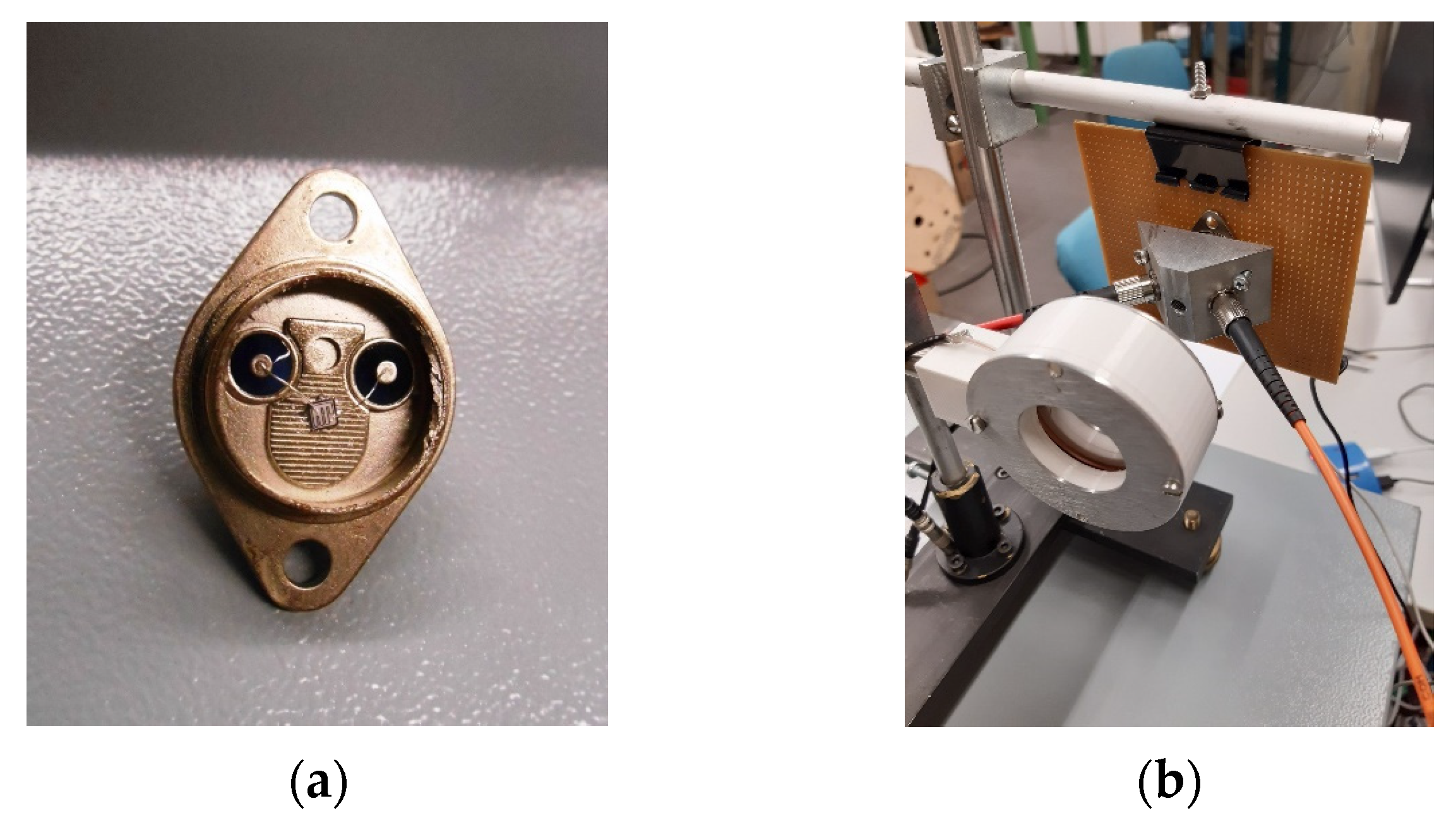
Figure 1a,b shows the experimental setup of the innovative dosimeter presented in this work. The dosimeter operating principle is based on the online detection of the light reflected by an RCF by using an optoelectronic instrumentation made of optical fibers (OFs), a spectrometer, and a light source.
In particular, two OFs are fixed on an aluminum support and point to a common vertex, where the RCF is placed. A cylindrical hole (6 mm diameter) allows the radiation to reach the RCF (and the DUT), without significantly perturbating the radiation field. The perturbation of the radiation field due to the RCF is indeed negligible for the intended applications as the RCF is made of a thin layer (in this work, 18 μm, 109 μm, or 278 μm, depending on the RCF type used) of a plastic-based material. The dosimeter’s materials and geometry were specifically designed to optimize the detection efficiency and to guarantee the maximum stability and reproducibility of the measurements. OFs are firmly connected to the metallic support by means of fiber optic connectors. Thus, the direction, the spot size, and the divergence of the light are determined by the geometry and are not influenced by any unwanted tilt of the OFs. The inclination angle of the OFs with respect to the hole has been selected to guarantee the minimum perturbation of the incident radiation with the maximum light detection efficiency.
One of the two OFs is connected to the light source, the other one to the spectrometer. In this geometry, the light emitted by the source reaches the RCF; its reflected component is collected by the second OF and is read by the spectrometer. In order to optimize the light collection efficiency, a thin layer of a reflective material (10 μm Al foil) is placed on the side of the RCF opposite to the fibers (
Figure 1b). The diameter of the core of the OF connected to the light source is 600 µm and that of the OF connected to the spectrometer is 200 µm. This configuration guarantees the uniformity of the light spot detected by the spectrometer. The light source, used in the current study, is the AvaLight-HAL-S-Mini halogen lamp, and the spectrometer is the AvaSpec-ULS2048XL-EVO (the latter is sensitive in a wavelength range of 200–1160 nm). The OFs are step-index, multimode, and solarization-resistant, operating in the wavelength range 180–1200 nm.
Figure 1c shows a typical wavelength spectrum in counts-per-second (CPS) acquired with this set up. The integration time of the spectra can be optimized for the specific measurement: typical values are in the range from tens to a few hundred of milliseconds.
RCF is the core of the dosimeter: during irradiation the RCF progressively darkens as a function of the dose and the spectrometer records the changes of the intensity of the reflected light.
This study demonstrates that it is possible to relate the darkening of the RCF to the dose imparted to the device. Thus, the use of this dosimeter in RHA tests allows for measurement in real-time of the dose delivered to the DUT, and to relate it to the DUT performance.
RCFs are suited for the dosimetry in several radiation fields. It has already been demonstrated that the RCF response is independent of the radiation type for protons; electrons; and X-, gamma-, and beta-rays. Furthermore, it has also been demonstrated that a setup based on OFs, a spectrometer, and a light source allows for real-time dosimetry with RCFs [
7,
8]. In the presented work, we optimize this dosimeter for real-time dosimetry in RHA.
Dose calibration of the RCF light spectra is necessary for a reliable definition of the dose, and it can be done by using different parameters, depending on the specific application. It is shown here that the most appropriate quantity for the calibration is the absorbance
A, and that the calibration depends on the dose and on the wavelength. Three types of RCFs are particularly suited for the dosimetry in RHA tests in terms of dose range: EBT3 Gafchromic films [
16] for low doses
, HDV-2 Gafchromic films [
17] for intermediate doses
, and Risø B3 films [
18] for high doses
.
Next Section presents the results of the experimental tests of the dosimeter exposed to different radiation environments: beta-rays from a 90Sr/90Y source, 19.9 MeV protons, and 1.02 MeV electrons. These radiation fields have been selected with the aim of covering all the typical irradiations of RHA tests. A reference dosimetry has been used in each experiment to validate the dose measurements of the proposed dosimeter.
3. Results
The innovative dosimeter, discussed in this paper, has been tested with three types of RCFs, namely the EBT3 gafchromic films, HDV-2 gafchromic films, and Risø B3 films. The parameter used to quantify the response of the dosimeter to radiation exposure was obtained by the analysis of the spectrum reflected by the RCFs.
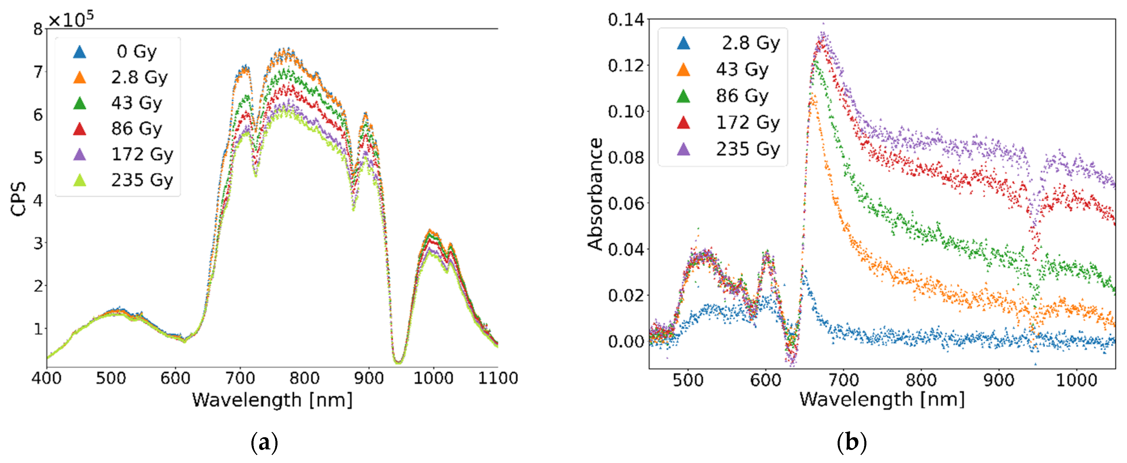
Figure 2a,
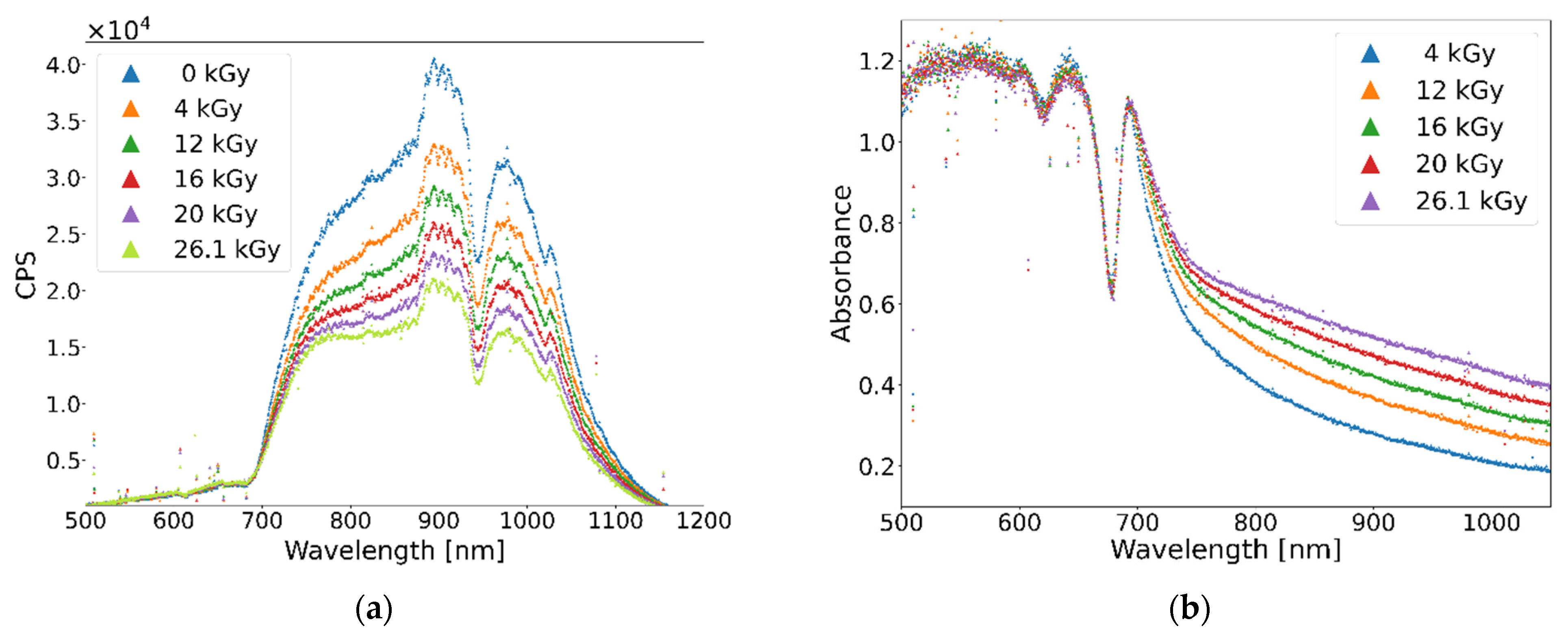
Figure 3a and
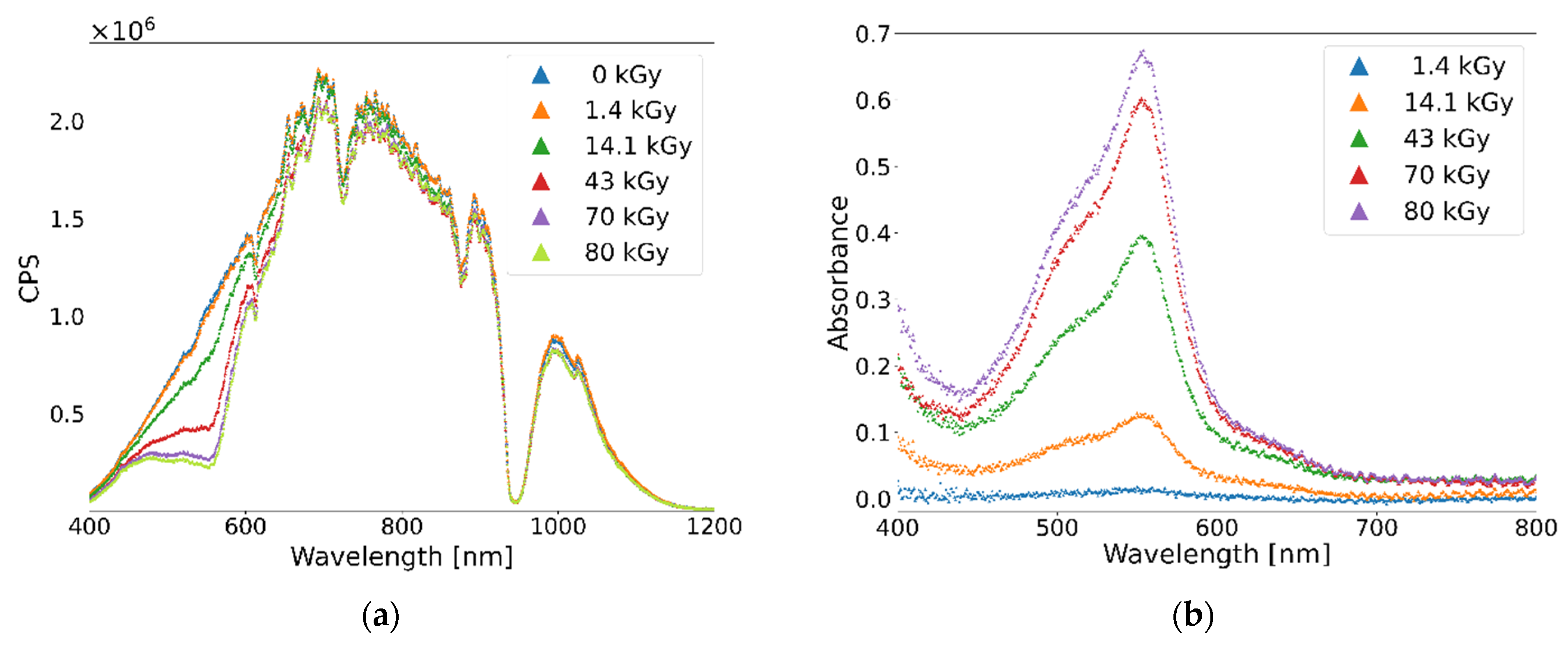
Figure 4a show the wavelength spectra of the three RCFs, namely EBT3, HDV-2, and B3, respectively. For each figure, the plot represents the reflected spectra of the RCF acquired during the exposure of the dosimeter at an increasing dose. The dose indicated here is measured with an auxiliary device used for calibration. For each RCF, the spectrum with the highest number of counts per second (cps) (blue line) refers to the RCF not exposed to radiation, whereas the other spectra refer to the RCF exposed at a given dose. It should be noted that as the dose increases, the reflected spectrum experiences a change in intensity, depending on both the dose and the wavelength.
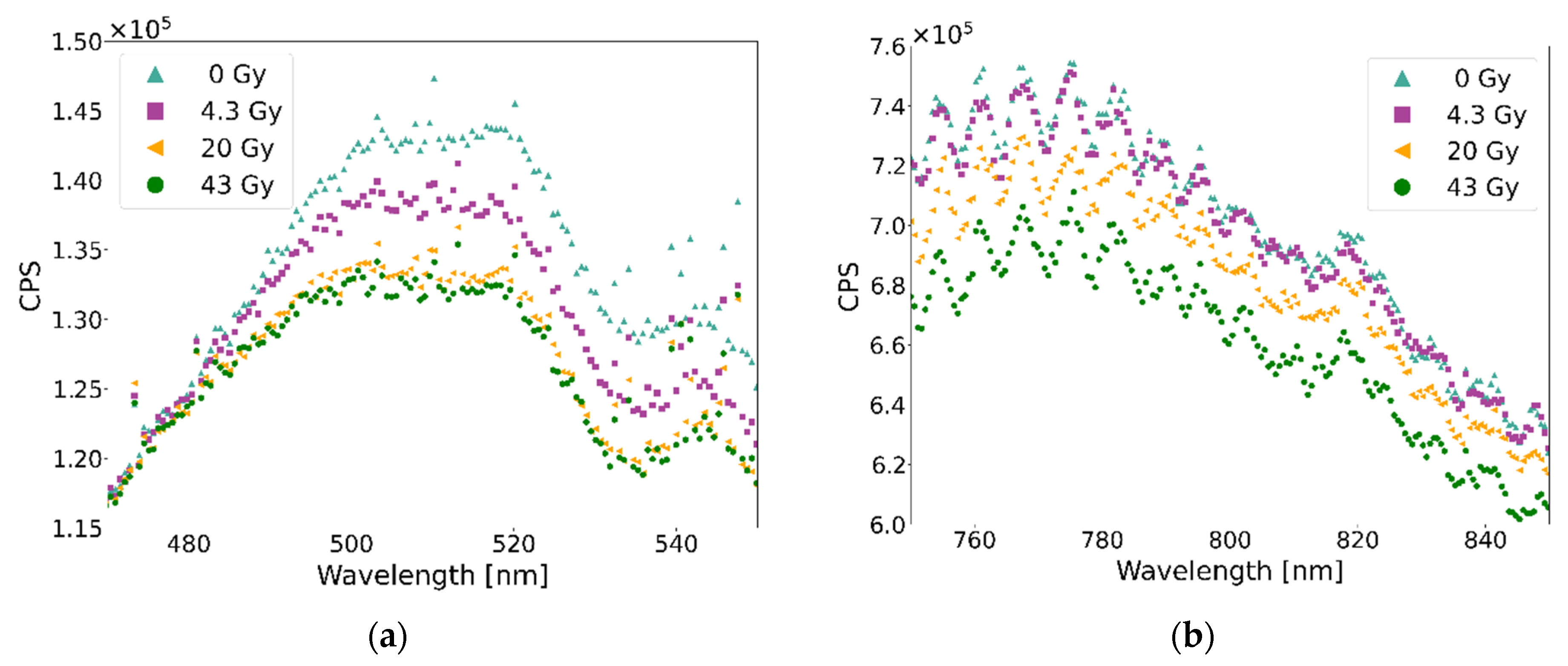
Figure 5 shows the zoom of the spectra reflected by the EBT3 gafchromic film in the wavelength ranges of 470–550 nm and 750–850 nm, respectively. The blue dots refer to the spectra of the RCF not exposed to the radiation, whereas the other spectra refer to doses of 4.3, 20, and 43 Gy. These acquisitions have been performed with a 38 MBq
90Sr/
90Y β source [
19]. The intensity of the spectrum at 4.3 Gy (magenta) at wavelength
λ = 500 nm decreases by 5% with respect to the spectrum at 0 Gy spectrum (cyan) at the same wavelength. On the contrary, the intensity of these two spectra at the wavelength
λ = 800 nm is the same, within experimental uncertainties. In addition, there is no measurable difference in intensity between the 20 and 43 Gy spectra at
λ = 500 nm, whereas for these two spectra, the intensity at
λ = 800 nm decreases by 6%. This behavior is observed for all of the RCF types analyzed, with a different dependence on the wavelength. Therefore, the sensitivity of the dosimeter can be optimized by analyzing the intensity at different wavelengths. The proposed technique allows for increasing the sensitivity of the dose measurement for RCFs.
The parameter used for the determination of the dynamic range and for the data calibration is the absorbance, defined as , where is the intensity of the spectrum at 0 Gy and is the intensity of the n-spectrum at an increasing dose.
The absorbance spectrum of the not-irradiated RCF is used as the reference spectrum. As the change in the spectrum is dependent on the wavelength, the definition of the dynamic dose range must be done for a fixed wavelength or for a narrow wavelength range. Once the wavelength is selected, the dynamic dose range is defined by analyzing the absorbance of the spectra at increasing doses at a fixed wavelength. The lower dynamic range limit, at a given
λ, is defined as the dose corresponding to the first spectrum with a measurable absorbance value. The latter refers to the first absorbance spectrum, which differs from the reference spectrum within the experimental uncertainties. The upper dynamic range limit is defined as the dose corresponding to the last absorbance spectrum, after which it is no longer possible to identify a measurable absorbance value: the absorbance spectra at increasing doses have same values, within experimental uncertainties, of the absorbance corresponding to the upper dose limit (the dosimeter response is saturated).
Figure 2b,
Figure 3b and
Figure 4b show the absorbance spectra for defined sets of doses for the three RCF types used.
Table 1 compares the RCF dynamic range declared by the manufacturer to the experimental one defined in this work.
In following subsections, the absorbance response of the dosimeter is illustrated as a function of dose for different RCFs. The dose calibration can be done by analyzing the absorbance curve at different wavelengths (or wavelength regions) depending on the specific RCF response. Therefore, the specific calibration function is dependent on the application and is not the purpose of this work.
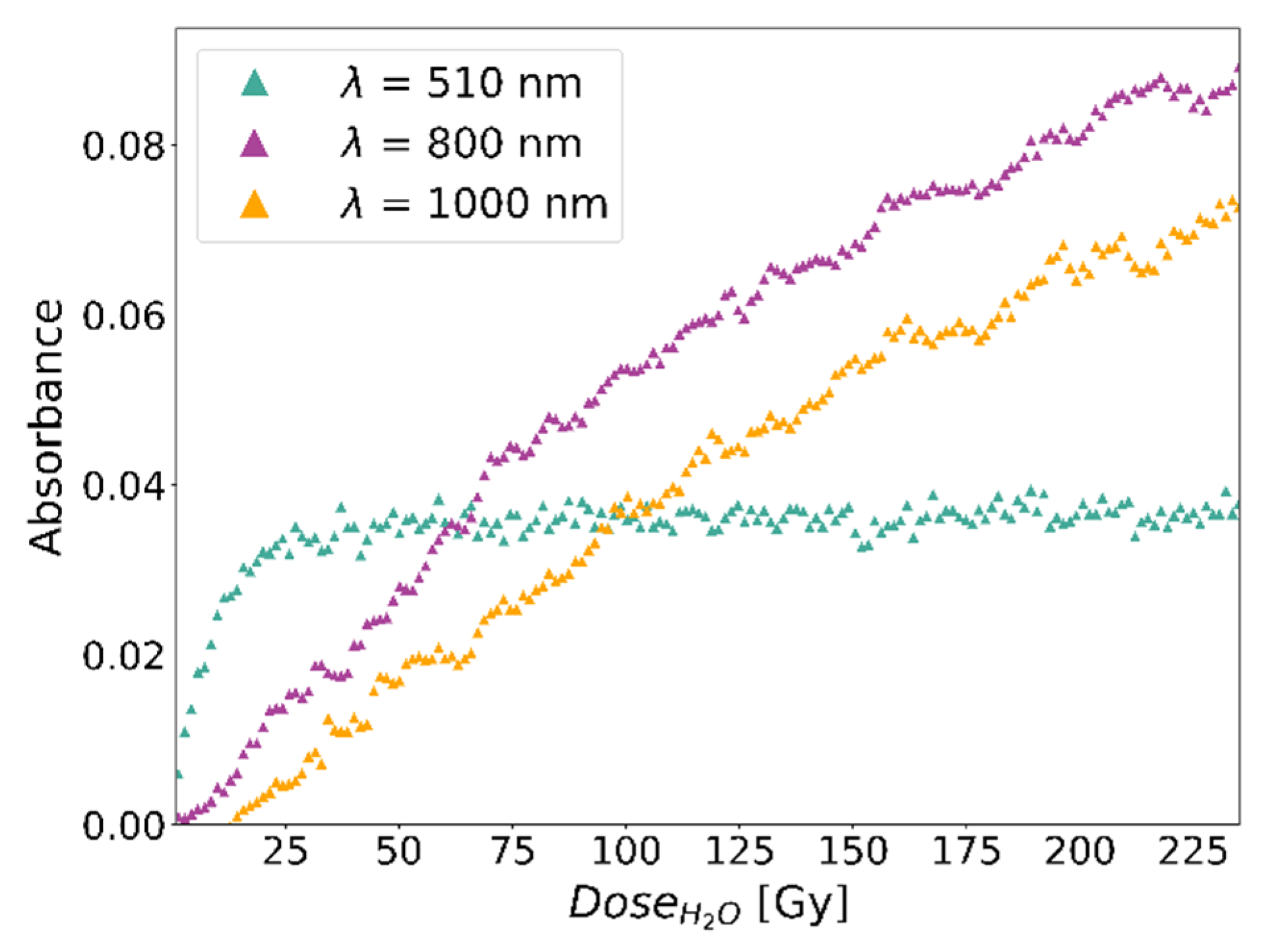
3.1. EBT3 Gafchormic Film
The new dosimeter was tested with an EBT3 film for the measurement of the radiation dose of the
90Sr/
90Y beta source, already introduced in the previous paragraph. The dose rate at a 0.2 cm distance from the source is 81 Gy/h. The maximum dose achieved in this test is 235 Gy. The dose difference between the two acquired spectra is 1 Gy.
Figure 6 shows the absorbance curves for three selected wavelengths. As shown in
Figure 6, it is possible to calibrate the dosimeter by selecting an appropriate wavelength at which the absorbance does not saturate in the dose range of interest. The absorbance increase at
λ = 510 nm allows for dose measurement in the range of 1–20 Gy. At higher doses, the absorbance at
λ = 510 nm is constant, resulting in a saturated response. The dose range of 29–210 Gy can be measured by analyzing the absorbance at
λ = 800 nm, while at
λ = 1000 nm is possible to measure the dose range of 8.6–210 Gy (
Table 1).
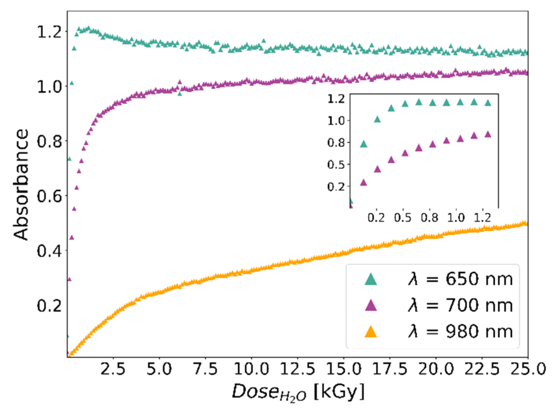
3.2. HDV-2 Gafchromic Film
The new dosimeter was tested with an HDV-2 film for the measurement of the radiation dose of a 19.9 MeV proton beam. The test was carried out at the Tandem MP accelerator of the Laboratori Nazionali del Sud (LNS) in Catania (Italy), with a continuous proton beam of 19.9 MeV energy and 350 pA current. The beam was extracted in air through a 50 µm thick Kapton window and collimated 5 mm diameter. The energy at the interaction point with the dosimeter was evaluated to be 19 MeV. During standard operations, the beam is monitored using Faraday cups positioned along the beam line. The Faraday cup positioned before the Kapton window and a custom ionization chamber were used for the calibration of the dosimeter. The maximum dose achieved in the test was 26.1 kGy. The dose difference between two acquired spectra is 130 Gy.
Figure 7 shows the absorbance curves at different wavelengths. The absorbance increase at
λ = 650 nm allows the dose measurement in the range 130–500 Gy. The extension of the dose range up to 8.6 and 26.1 kGy can be obtained by evaluating the absorbance at
λ = 700 and
λ = 980 nm respectively (see
Table 1).
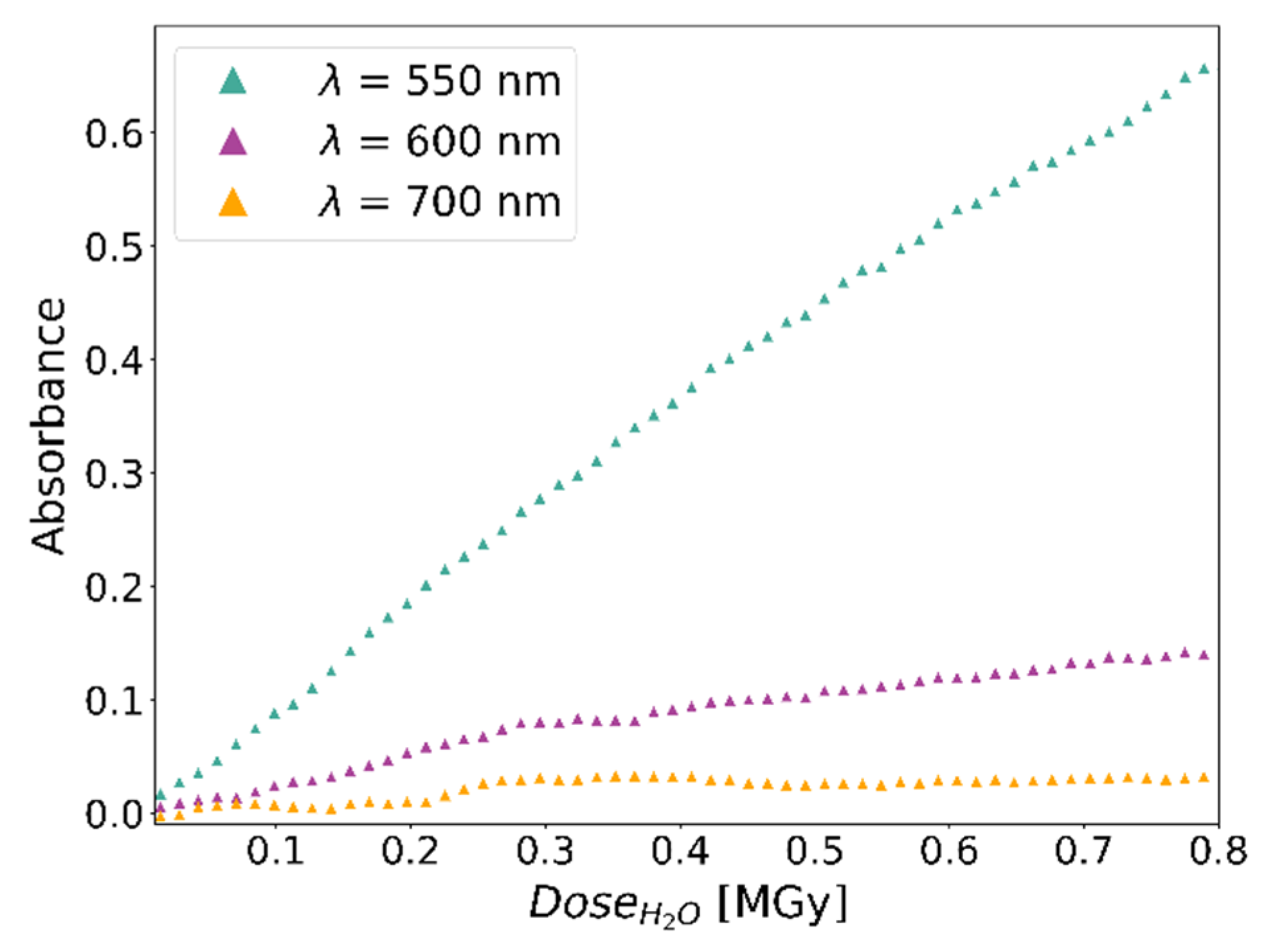
3.3. B3 Risø Film
The new dosimeter was tested with a Risø B3 film for the measurement of the radiation dose of a 1.02 MeV electron beam. The test was performed with the ILU-6 accelerator of the Institute of Nuclear Chemistry and Technology (INCT), in Warsaw. The accelerator produces pulses of electrons up to 2.5 MeV and 20 mA peak current. The frequency of the pulses can be adjusted from 2 Hz to 50 Hz. The experiment was carried out with a beam of 1.02 MeV energy, 3 mA peak current, 5 Hz frequency and 365 µs pulse width. The outgoing beam was extracted vertically in air through a 50 µm titanium window. A magnetic deflector scans the beam on a surface up to 40 × 8 cm
2. The electron flux was monitored by measuring the charge collected by an aluminum plate positioned perpendicularly to the beam direction. The plate was placed at the same distance of the RCF. With this set up, it was possible to measure the electron flux on the RCF. The maximum dose achieved is 0.8 MGy. The dose difference between two acquired spectra is 1 kGy.
Figure 8 shows the absorbance curves as a function of the dose for three selected wavelengths. For B3 films, the calibration curves at wavelengths of
λ = 550 nm and
λ = 600 nm allow to measure a dose up to 0.8 MGy. The curve at
λ = 700 nm saturates at about 5 kGy, resulting in a measurable dose in the range 1–2 kGy (see
Table 1).
3.4. Validation of Operating Environment
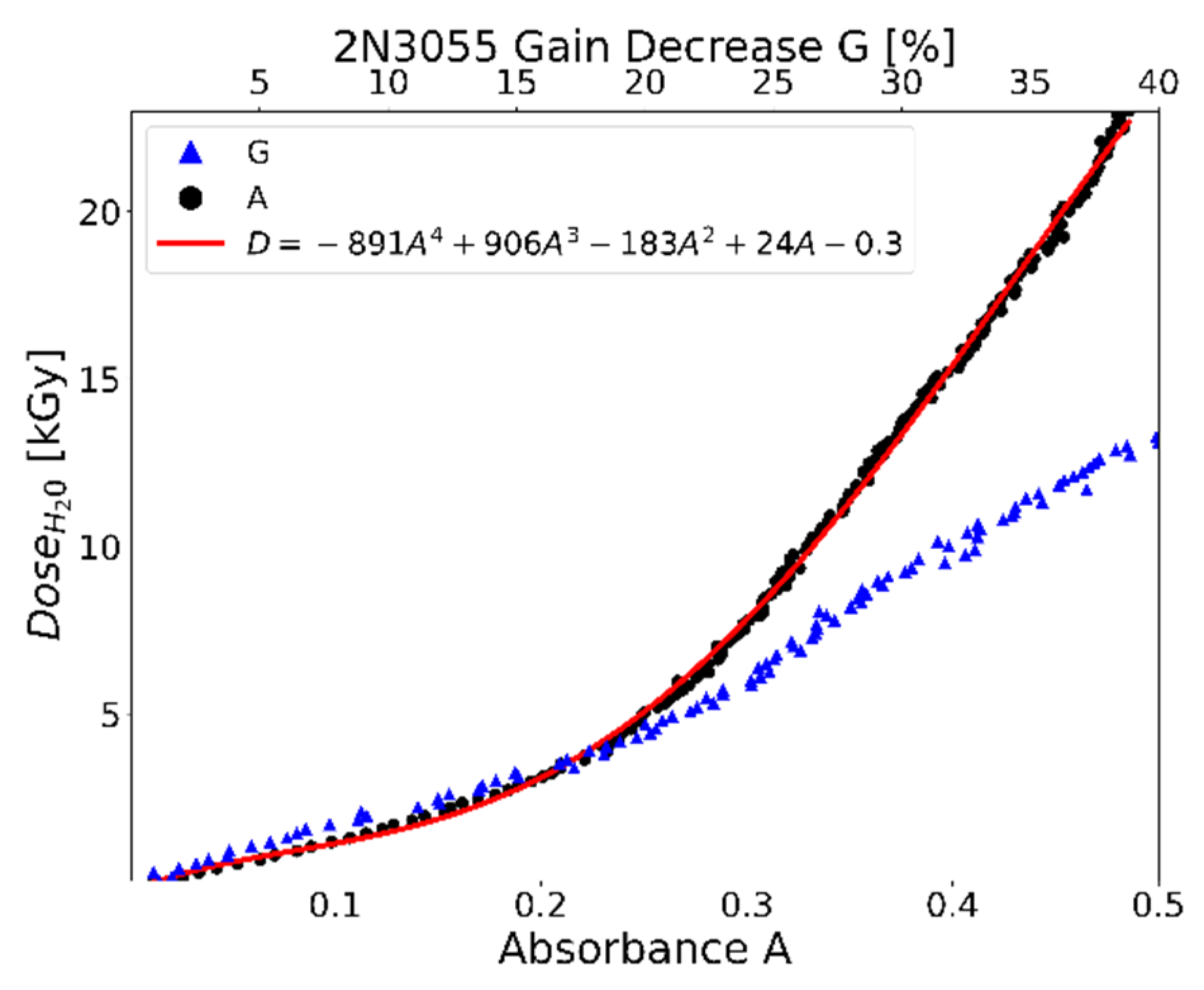
The new dosimeter was tested in an operational environment for the study of the radiation damage on electronic devices and materials. As an operative example, a radiation hardness test of a 2N3055 transistor is performed with a proton beam of 19.1 MeV at the tandem MP accelerator of the LNS. The 2N3055 is a silicon NPN bipolar transistor used in a variety of high-power applications. It is commercialized in a TO3 metallic package, whose top side has been removed in order to allow the proton beam to reach the DUT without energy degradation (
Figure 9a). The proton beam, after being extracted in air through a Kapton window, passes through the ionization chamber, used as a reference dosimeter. Downstream, there is the dosimeter with an HDV-2 film and the 2N3055 transistor.
Figure 9b shows the experimental layout for this test.
The transistor is powered and connected to an electronic circuit, which allows for evaluation of the transistor gain in real-time. The maximum dose achieved in this test was 25 kGy.
Figure 10 shows the relative gain decrease of the transistor, as well as the absorbance of the HDV-2 gafchromic film as a function of the dose measured with the ionization chamber. The transistor experienced a gain reduction by 40% of its original value. This degradation can be ascribed to the increase of the recombination rate in the base region due to radiation-induced defects at the base interface, which turn into a strong reduction of the collector current.
4. Discussion
The dosimeter was successfully tested with a beta source and with electron and proton beams. The test with the DUT confirms that the designed prototype dosimeter can be used for dosimetry in compact geometries of the experimental set up, with a negligible perturbation of the radiation field. In addition, the compactness of the presented dosimeter allows for its use in harsh environments, such as particle accelerator facilities for nuclear and high energy physic experiments. The most interesting characteristic of this dosimeter is the capability to provide a real-time dose response on the DUT and to detect any changes of the particle flux during the irradiation.
The new RCF reading method allows for dose measurement by evaluating the relative darkening of the RCF and by performing a real-time dynamic calibration. Thus, in addition to the features of the established RCF dosimetry [
20], the new RCF reading method allows for real-time dose measurement during irradiation. By changing the RCF, the dosimeter can be adapted to monitor doses of a different order of magnitude, corresponding to different application fields. Given an RCF type, the analysis of the real-time absorbance spectrum allows for the extension of the RCF dynamic range. The overall dynamic range is 1.4 Gy–0.8 MGy.
The relation between the optical spectra and the dose is given by the calibration curve obtained from the absorbance spectra. From the absorbance curve, it is clear that the response of RCF depends on the dose and the wavelength analyzed. For the EBT3 films, the dose sensitivity can be increased by analyzing the absorbance at 800 and 1000 nm. For HDV-2 films, the calibration curve at 980 nm allows for extending the dynamic range up to 26.1 kGy. The B3 film dynamic range is extended to 0.8 MGy by analyzing 550 and 600 nm.
It is known that optical fibers experience radiation damage, which translates into the attenuation of the spectrum as a function of the dose [
21]. Being the proposed dosimeter based on optical fibers for the real-time RCF reading, the radiation damage of optical fibers is a scientific issue to be considered. Indeed, the Al holder for the optical fibers was specifically designed to minimize their interaction with the primary beam. In particular, the optical fibers are not exposed to radiation for both the test with the beta source and with the proton beam. In these cases, the primary radiation field interacts only with the RCF and with the DUT. For the test with the electron beam, a part of the fibers (about 2 cm each fiber) was exposed to the expanded radiation field from the electron beam. As a result, the optical fibers were shielded by means of a 2 mm lead sheath.
5. Conclusions
In this paper, an innovative dosimeter for radiation hardness assurance (RHA) tests that uses a spectrometer and two optical fibers for dosimetric real-time spectral measurements of radiochromic films (RCFs) is developed. The specific geometry allows (1) for minimizing the interaction of the primary radiation field with the optical fibers, and (2) to improve the measurement reproducibility by keeping the relative positions of the optical fibers and of the RCF fixed. The optimization of the design (geometry and material) of this dosimeter can pave the way to the development of new real-time dosimeters in critical applications, such as the dosimetry monitoring in radiotherapy.
Foreseen improvements involve the development of a dynamic algorithm that allows for selecting the wavelength to analyze during the irradiation according to the experimental needs and to instantaneously obtain the dose value. A further project goal is the development of a user-friendly graphical user interface.
Author Contributions
Conceptualization, L.C.; data curation, L.C., P.C. and E.M.G.; funding acquisition, L.C., P.C. and S.B.; investigation, L.C., P.C., E.M.G. and F.D.C.; methodology, L.C. and P.C.; project administration, L.C. and P.C.; resources, L.C., P.C. and S.B.; supervision, L.C. and S.B.; validation, L.C., P.C., E.M.G., M.C. and F.D.C.; visualization, E.M.G.; writing—original draft, L.C. and E.M.G.; writing—review and editing, L.C., P.C., E.M.G., M.C. and F.D.C. All of the authors will be informed about each step of manuscript processing including submission, revision, revision reminder, etc., via emails from our system or the assigned Assistant Editor. All authors have read and agreed to the published version of the manuscript.
Funding
This research was funded by the National Institute of Nuclear Physics (INFN) in the framework of the Technology Transfer project OPTORAD.
Data Availability Statement
Not applicable.
Acknowledgments
The authors would like to express their gratitude to Marco Durante for supporting this project, as well as for valuable discussions. The authors are also grateful to Giovanni La Rana for the support provided to the project. The authors acknowledge contributions from the staff of the INFN Laboratori Nazionali del Sud (LNS), Catania, Italy, and of the Institute of Nuclear Chemistry and Technology (INCT), Warsaw, Poland, for the help provided during the irradiations.
Conflicts of Interest
The authors declare no conflict of interest.
References
- Schwank, J.R.; Shaneyfelt, M.R.; Dodd, P.E. Radiation hardness assurance testing of microelectronic devices and integrated circuits: Radiation environments, physical mechanisms, and foundations for hardness assurance. IEEE Trans. Nucl. Sci. 2013, 60, 2074–2100. [Google Scholar] [CrossRef]
- Campajola, L.; Di Capua, F. Application of accelerator and radiation sources in the field of space research and industry. Top. Curr. Chem. 2016, 374, 84. [Google Scholar] [CrossRef] [PubMed]
- ESCC Basic Specification No. 22900; Total Dose Steady-State Irradiation Test Method. 2010. Available online: http://escies.org/escc-specs/published/22900.pdf (accessed on 6 March 2022).
- ESCC Basic Specification No. 22500; Guidelines for Displacement Damage Irradiation Testing. 2019. Available online: https://www.doeeet.com/content/eee-components/escc-22500-guidelines-for-displacement-damage-irradiation-testing/ (accessed on 6 March 2022).
- ESCC Basic Specification No. 25100; Single Event Effects Test Method and Guidelines. 2014. Available online: http://sirad.pd.infn.it/~candelor/Parte2A/Parte2A_06_NormeESA_25100_2014October.pdf (accessed on 6 March 2022).
- Casolaro, P.; Campajola, L.; de Luca, D. Radiochromic films in radiation hardness space application. J. Phys. Conf. Ser. 2019, 1226, 012006. [Google Scholar] [CrossRef]
- Campajola, L.; Casolaro, P.; Di Capua, F. Absolute dose calibration of EBT3 gafchromic films. JINST 2017, 12, P08015. [Google Scholar] [CrossRef]
- Casolaro, P.; Campajola, L.; Breglio, G.; Buontempo, S.; Consales, M.; Cusano, A.; Cutolo, A.; Di Capua, F.; Fienga, F.; Vaiano, P. Real-time dosimetry with radiochromic films. Sci. Rep. 2019, 9, 5307. [Google Scholar] [CrossRef] [PubMed] [Green Version]
- Casolaro, P.; Campajola, L.; Breglio, G.; Buontempo, S.; Consales, M.; Cusano, A.; Cutolo, A.; Di Capua, F.; Fienga, F.; Vaiano, P. Absolute Calibration for film dosimetry. Int. J. Mod. Phys. Conf. Ser. 2020, 50, 2060012. [Google Scholar] [CrossRef]
- Fienga, F.; Casolaro, P.; Vaiano, P.; Di Capua, F.; Campajola, L.; Breglio, G.; Cutolo, A.; Consales, M.; Buontempo, S.; Cusano, A. An Innovative Extrinsic Fiber Optic Sensor for Real-Time Radiation Monitoring; Optical Fiber Sensors Conference 2020 Special Edition; Cranch, G., Wang, A., Digonnet, M., Dragic, P., Eds.; OSA Technical Digest (Optica Publishing Group): Washington, DC, USA, 2020; p. Th3B.4. [Google Scholar] [CrossRef]
- Casolaro, P. Innovative Detection Methods for Radiation Hardness. Ph.D. Thesis, University of Napoli Federico II, Napoli, Italy, 2019. [Google Scholar] [CrossRef]
- Casolaro, P.; Breglio, G.; Buontempo, S.; Campajola, L.; Consales, M.; Cusano, A.; Cutolo, A.; Di Capua, F.; Fienga, F.; Vaiano, P. An innovative dosimetry method for accurate and real time dose assessment for Radiation Hardness Assurance tests. In Proceedings of the 18th European Conference on Radiation and Its Effects on Components and Systems (RADECS), Göteborg, Sweden, 16–21 September 2018; pp. 1–4. [Google Scholar] [CrossRef]
- Vaiano, P.; Consales, M.; Casolaro, P.; Campajola, L.; Fienga, F.; Di Capua, F.; Breglio, G.; Buontempo, S.; Cutolo, A.; Cusano, A. A novel method for EBT3 Gafchormic films read-out at high dose levels. Phys. Med. Eur. J. Med. Phys. 2019, 61, 77–84. [Google Scholar] [CrossRef]
- Casolaro, P. Radiochromic Films for the Two-Dimensional Dose Distribution Assessment. Appl. Sci. 2021, 11, 2132. [Google Scholar] [CrossRef]
- PatentScope—Method and System for Real-Time Determination of Characteristics of Radiochromic Films. Available online: https://patentscope.wipo.int/search/en/detail.jsf?docId=WO2019138309&_cid=P11-K06MK9-10214-1 (accessed on 6 March 2022).
- Gafchromic. Dosimetry Media, Type EBT-3. Available online: http://www.gafchromic.com/documents/EBT3_Specifications.pdf (accessed on 6 March 2022).
- Gafchromic. Dosimetry Media, Type HD-V2. Available online: http://www.gafchromic.com/documents/gafchromic-hdv2.pdf (accessed on 6 March 2022).
- Gex Corporation. B3 Radiochromic Film Dosimeters. Available online: https://www.gexcorp.com/pdf/2013%20Product%20Spec_B3%20Products.pdf (accessed on 6 March 2022).
- Di Capua, F.; Campajola, L.; Casolaro, P.; Aloisio, A.; Lucaroni, A.; Furano, G.; Menicucci, A.; Di Mascio, S.; Malatesta, F.; Ottavi, M. Full Characterization of a Compact 90Sr/90Y beta source for TID radiation testing. Adv. Space Res. 2019, 63, 3249–3257. [Google Scholar] [CrossRef]
- ANiroomand-Rad, A.; Chiu-Tsao, S.; Grams, M.P.; Lewis, D.F.; Soares, C.G.; Van Battum, L.J.; Das, I.J.; Trichter, S.; Kissick, M.W.; Massillon-Jl, G.; et al. Report of AAPM Task Group 235 Radiochromic Film Dosimetry: An Update to TG-55. Am. Assoc. Phys. Med. Med. Phys. 2020, 47, 5986–6025. [Google Scholar] [CrossRef]
- Girard, S.; Morana, A.; Ladaci, A.; Robin, T.; Mescia, L.; Bonnefois, J.-J.; Boutillier, M.; Mekki, J.; Paveau, A.; Cadier, B.; et al. Recent advances in radiation-hardened fiber-based technologies for space applications. J. Opt. 2018, 20, 093001. [Google Scholar] [CrossRef] [Green Version]
Figure 1.
Picture (a) and scheme (b) of the dosimeter. The radiation interacts with the radiochromic film (RCF, green in the scheme (b)), which darkens as a function of the dose. Two optical fibers (OFs) point at the RCF. One optical fiber transports the light from a light source, the other one acquires the light reflected by the RCF. An aluminum foil is placed on the side of the RCF not exposed to the light, in order to increase the collection of the reflected light. The device under test (DUT) is placed behind the RCF as the radiation first passes through the RCF and then it reaches the DUT. (c) Typical spectrum in counts-per-second (CPS) of an EBT3 Gafchromic film acquired with this setup.
Figure 2.
Reflection (a) and absorbance spectra (b) of EBT3 gafchromic film exposed to different doses from a 38 MBq 90Sr/90Y beta source. The dose was evaluated knowing the dose-rate of the source.
Figure 2.
Reflection (a) and absorbance spectra (b) of EBT3 gafchromic film exposed to different doses from a 38 MBq 90Sr/90Y beta source. The dose was evaluated knowing the dose-rate of the source.
Figure 3.
Reflection (a) and absorbance spectra (b) of HDV-2 gafchromic film exposed to different doses from a 19.9 MeV proton beam. The dose was measured by means of an ionization chamber used for the calibration of the dosimeter.
Figure 3.
Reflection (a) and absorbance spectra (b) of HDV-2 gafchromic film exposed to different doses from a 19.9 MeV proton beam. The dose was measured by means of an ionization chamber used for the calibration of the dosimeter.
Figure 4.
Reflection (a) and absorbance spectra (b) of Risø B3 film exposed to different doses from a 1.02 MeV electron scanned beam. The dose was measured by monitoring the flux of the electrons on an aluminum plate placed at the same position as the dosimeter.
Figure 4.
Reflection (a) and absorbance spectra (b) of Risø B3 film exposed to different doses from a 1.02 MeV electron scanned beam. The dose was measured by monitoring the flux of the electrons on an aluminum plate placed at the same position as the dosimeter.
Figure 5.
EBT3 gafchromic film reflection spectra in the wavelength range 470–550 nm (a) and in the wavelength range of 750–850 nm (b). Spectra at different doses have been obtained with a 38 MBq 90Sr/90Y beta source.
Figure 5.
EBT3 gafchromic film reflection spectra in the wavelength range 470–550 nm (a) and in the wavelength range of 750–850 nm (b). Spectra at different doses have been obtained with a 38 MBq 90Sr/90Y beta source.
Figure 6.
Absorbance as a function of the dose for the dosimeter with EBT3 gafchromic film for the dose measurement of the radiation field from a 90Sr/90Y beta source.
Figure 6.
Absorbance as a function of the dose for the dosimeter with EBT3 gafchromic film for the dose measurement of the radiation field from a 90Sr/90Y beta source.
Figure 7.
Absorbance as a function of the dose for the dosimeter with an HDV-2 gafchromic film for the dose measurement of the radiation field from a 19.9 MeV proton beam. The inset shows a zoom of the graph in the dose range of 0–1.3 kGy.
Figure 7.
Absorbance as a function of the dose for the dosimeter with an HDV-2 gafchromic film for the dose measurement of the radiation field from a 19.9 MeV proton beam. The inset shows a zoom of the graph in the dose range of 0–1.3 kGy.
Figure 8.
Absorbance as a function of the dose for the dosimeter with a B3 Risø film for the dose measurement of the radiation field from a 1.02 MeV energy electron beam. λ denotes the wavelength.
Figure 8.
Absorbance as a function of the dose for the dosimeter with a B3 Risø film for the dose measurement of the radiation field from a 1.02 MeV energy electron beam. λ denotes the wavelength.
Figure 9.
(a) The top side of the transistor is removed to expose its sensitive part to the beam. (b) Picture of the experimental apparatus for the irradiation of the 2N3055 transistor.
Figure 9.
(a) The top side of the transistor is removed to expose its sensitive part to the beam. (b) Picture of the experimental apparatus for the irradiation of the 2N3055 transistor.
Figure 10.
The dose measured with the ionization chamber versus the absorbance increase, A, of the HDV-2 gafchromic film at 980 nm (black) and the gain, G, decrease of the transistor (blue). For this application, the absorbance curve A is fitted with a fourth-order polynomial function, D (red line).
Table 1.
Comparison of the dynamic range, declared by the manufacturer, to the experimental one, defined in this study for EBT3 gafchromic films, HDV-2 gafchromic films, and Risø B3 films. λ denotes the wavelength.
Table 1.
Comparison of the dynamic range, declared by the manufacturer, to the experimental one, defined in this study for EBT3 gafchromic films, HDV-2 gafchromic films, and Risø B3 films. λ denotes the wavelength.
| Radiochromic Film (RCF) | Datasheet | Experimental Results |
|---|
| λ [nm] | Dose Range |
|---|
| Gafchromic EBT3 | 0.1–20 Gy | 510 nm
800 nm
1000 nm | 1.4–16 Gy
29–210 Gy
8.6–210 Gy |
| Gafchromic HDV-2 | 0.01–1 kGy | 650 nm
700 nm
980 nm | 0.13–0.5 kGy
0.13–8.6 kGy
0.13–26.1 kGy |
| Risø B3 | 0.5–200 kGy | 550 nm
600 nm
700 nm | 1–800 kGy
1–800 kGy
1–2 kGy |
| Publisher’s Note: MDPI stays neutral with regard to jurisdictional claims in published maps and institutional affiliations. |
© 2022 by the authors. Licensee MDPI, Basel, Switzerland. This article is an open access article distributed under the terms and conditions of the Creative Commons Attribution (CC BY) license (https://creativecommons.org/licenses/by/4.0/).


 ,
, 


