NVH Optimization Analysis of Permanent Magnet Synchronous Motor by Rotor Slotting

1
Automotive Engineering Research Institute (AERI), China Automotive Technology and Research Center Co., Ltd. (CATARC), Tianjin 300300, China
2
Tianjin Key Laboratory for Advanced Mechatronic System Design and Intelligent Control, School of Mechanical Engineering, Tianjin University of Technology, Tianjin 300384, China
*
Author to whom correspondence should be addressed.
Vehicles 2020, 2(2), 287-302; https://0-doi-org.brum.beds.ac.uk/10.3390/vehicles2020016
Submission received: 24 February 2020
/
Revised: 31 March 2020
/
Accepted: 18 April 2020
/
Published: 20 May 2020
(This article belongs to the Special Issue Rotordynamics in Automotive Engineering)
Abstract
:With the development of new energy vehicles, the NVH (Noise, Vibration, Harshness) performance of the permanent magnet synchronous motors (PMSM) for vehicles has attracted more and more attention. The rotor slotting optimization analysis is the critical issue in the NVH performance study of PMSM. In this paper, the theoretical formula of the PMSM radial electromagnetic force is presented. Based on which, the spatial order and frequency order characteristics of the radial force of a 6-pole 36-slot PMSM are analyzed. Firstly, electromagnetic simulation of the motor is carried out, and the specific force components, which may cause an NVH problem, is extracted. Secondly, the harmonics are calculated with a method of freezing the relative magnetic permeability. Thirdly, the motor is optimized by rotor slotting to reduce the amplitudes of these harmonics, and the effect on electromagnetic noise is analyzed in theory and simulation. Finally, the NVH test in original state and after rotor slotting state was performed in the semi-anechoic chamber. The accuracy of the theory and simulation was verified based on the comparison of the measured noise data. This paper provides a new NVH optimization idea, this method can quickly locate the fundamental problem location of electromagnetic NVH, provide a fast channel for electromagnetic NVH optimization from simulation to verification, and improve the optimization efficiency of NVH.
1. Introduction
With the development of new energy vehicles, the NVH performance of the permanent magnet synchronous motors (PMSM) for vehicles has attracted more and more attention [1,2,3,4].
A relative permeance function for the slotted machine was proposed in [5] to modulate the radial component of flux density distribution predicted by the slotless model, which has received extensive applications in the surface permanent magnet motor (SPMM) for predicting radial force. In [6,7,8,9], radial electromagnetic force is calculated by the finite element method, and the influence of radial electromagnetic force on noise and vibration is studied. The pole-slot combination of PMSM is one of the key issues affecting its NVH. In [10,11,12,13], the air gap magnetic flux density and electromagnetic force were obtained by the finite element method to study the influence of the pole-slot combination of the motor on vibration and noise. In [14], by coupling the analysis model with the finite element model, the hybrid model takes into account the permeability, slot height, and rotor shape, and calculates the complex global air-gap permeability per unit area, which makes the calculation of air-gap magnetic density with high accuracy and calculation speed. In [15], it is proposed that the lower harmonic components of the radial electromagnetic force is mainly due to the interaction between the magnet field and the armature-reaction field, which is largely determined by the combination of the pole and slot numbers, and it is much more reliable to calculate the radial force in the middle of the air gap rather than close to the stator bore. Zuo et al. [16] proposed that the electromagnetic force caused by stator slotting effect contributes most to the overall noise. In addition, with reducing the amplitude of the electromagnetic force, which is close to the resonant frequency by optimizing the slot width, the sound pressure level (SPL) is reduced by 6 dB (A). It is also raised in the paper that to reduce the vibration and noise of the motor, optimizing the electromagnetic force or increasing the structural stiffness both works. However the latter is costly, so the most widely used method is to avoid the electromagnetic force appearing near the modal frequency. In [17], a combined simulation of electromagnetic field, mechanical field, and acoustic field was applied to predict the vibration and noise of a three-phase 12-pole 36-slot claw pole alternators. Simulation results agree well with the results measured by experiments. Results show that the vibration and noise of the motor is mainly caused by the electromagnetic force of spatial order 0 and order 6. In [18], in order to reduce the rated unbalanced magnetic force, three 3-slot/2-pole permanent magnet (PM) motors with different auxiliary slots were studied and compared. A 2D finite element method is introduced, and its unbalanced magnetic force characteristics are analyzed, and the unbalanced magnetic force with different auxiliary slots is studied. It is mentioned in [19] that reducing harmonic components of the air gap flux density can effectively attenuate the cogging torque and suppress the torque ripple, thereby reducing motor vibration. This goal is achieved in the paper by the means of optimizing the shape of the permanent magnet and the shape of the rotor surface. In [20], a slotted rotor configuration is proposed to reduce the torque ripple and radical vibration force. The flux density distributions are discussed to explain the principle that the torque ripple and radical vibration of motor is smaller with a slotted rotor and skew-slot stator.
In this paper, a 6-pole 36-slot vehicle PMSM is studied. The spatial order and frequency order of the electromagnetic force of the motor are analyzed. In addition, the motor is optimized by rotor slotting to weaken the electromagnetic force and improve the motor NVH performance. This paper provides a new NVH optimization idea, that is, first of all, the mechanism analysis of the problematic electromagnetic order noise is decomposed, and the related harmonics are decomposed. Under the premise that other factors are unchanged, reducing the amplitude of these harmonics can achieve the purpose of optimizing the electromagnetic order noise. This method can quickly locate the fundamental problem location of electromagnetic NVH, provide a fast channel for electromagnetic NVH optimization from simulation to verification, and improve the optimization efficiency of NVH.
2. Spatial Order and Frequency Order Analysis of the Radial Electromagnetic Force
Ignoring the influence of the tangential component of the air gap magnetic field, the radial electromagnetic force density of the PMSM can be calculated according to the Maxwell tensor equation as follows:
where, θ is the angular position in the stator steady frame, t is the time, μ0 is air gap magnetic permeability, and br(θ,t) is the radial air gap flux density, which can be expressed as:
where, fm(θ,t) is the magnetomotive force (MMF) of the permanent magnet, fs(θ,t) is the armature MMF, and λ(θ,t) is the air gap permeance.
Ignoring the slotting effect of the stator, the MMF of the permanent magnet is as follows:
where, p is the pole pairs, w is the angular velocity, and Fu is the amplitude of the μth MMF.
Ignoring the harmonics of the current [21], the MMF of the armature is:
where, Fv is the amplitude of the υth MMF.
Considering the effect of stator slotting, the air gap permeance can be determined as:
where, λ0 is the amplitude of the static component of the air gap permeance, λi is the amplitude of the ith component, and Z is the number of slots.
Applying Equations (2)–(5) to Equation (1), the radial electromagnetic force density can be determined as:
The radial vibration amplitude of the motor is closely related to the spatial orders and frequencies of the electromagnetic force, as shown in the following equation [22]:
where, n is the spatial order of the radial electromagnetic force, Pr and fn is the corresponding amplitude and frequency respectively, and fmo is the radial modal frequency of the motor.
According to Equation (6), the spatial order and frequency order characteristics of the radial electromagnetic force of the 6-pole 36-slot PMSM can be obtained, as shown in Table 1:
In Table 1, “Unload” means that the output torque is 0 when the motor is running, “Full Load” means the maximum output torque corresponding to the current speed of the motor. As can be seen from the table, except for the 0th order, the spatial orders and frequency orders of the 6-pole 36-slot PMSM are integer multiples of 6, and the lowest order is 6. It can be known from Equation (7) that the radial vibration amplitude of the motor is proportional to the amplitude of the electromagnetic force and inversely proportional to the fourth power of its spatial order, so the low-order components of the electromagnetic force is the main cause of vibration and noise. For a 6-pole 36-slot PMSM, the force harmonics with 0th and 6th spatial orders are the main factors causing the vibration and noise of the motor. Additionally when the 0th and 6th modal frequencies of the motor are equal to or close to the force harmonics frequencies of the corresponding order, it will cause resonance [23]. In other cases, forced vibration may occur in the motor.
3. Simulation Analysis of the Radial Electromagnetic Force
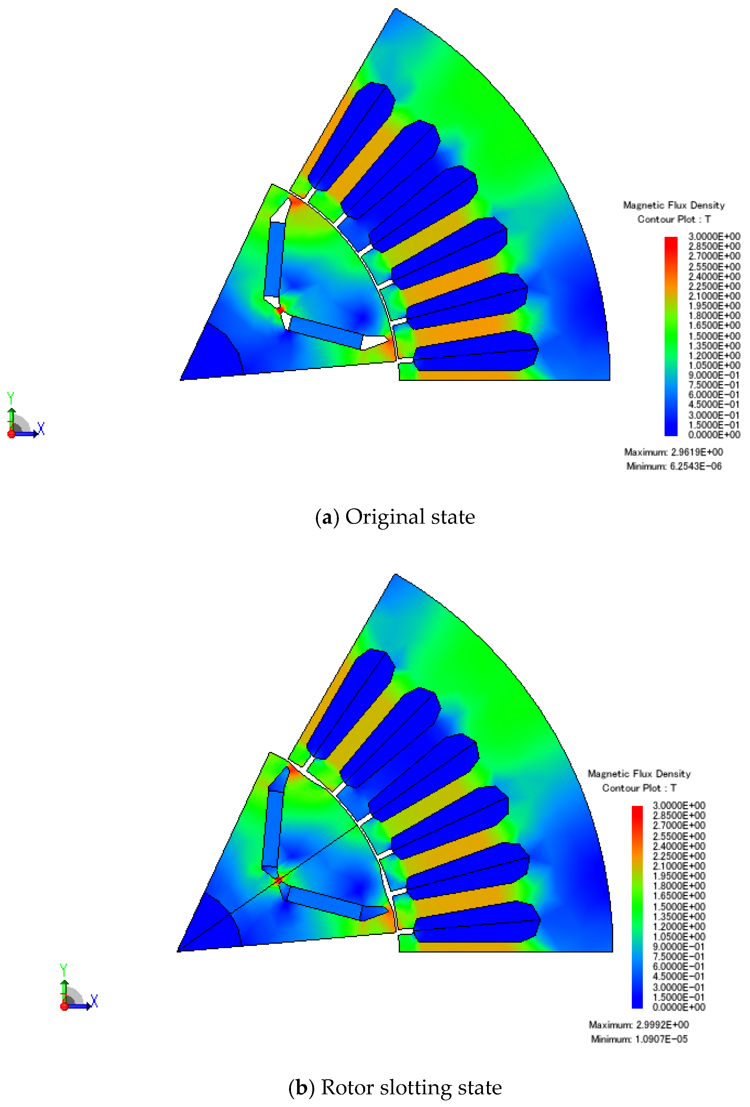
The structural parameters of the motor are shown in Table 2. The 2D model of the motor is established with the simulation software to obtain the electromagnetic force. Since the magnetic circuit of the motor is symmetrical, it can be equivalent to a 1-pole 6-slot unit motor model, and the simulation results of the full model can be obtained by using the symmetry boundary conditions. Figure 1a,b shows the magnetic flux density distribution of the original motor and the optimized motor by rotor slotting. Due to the slotting effect, the rotor structure of the motor has changed, the length of the air gap as well as the magnetic flux density at the slot position has been changed, and then the magnetic circuit of the rotor has been changed consequently.
3.1. Harmonics of the Radial Electromagnetic Force
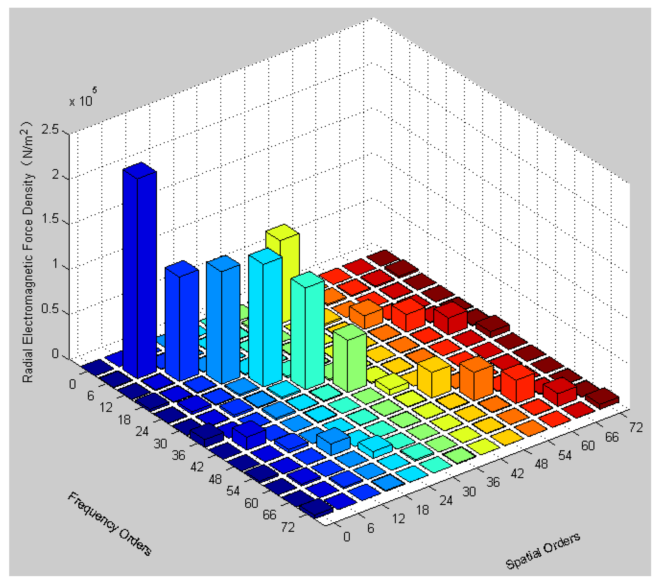
The magnetic flux density at the middle position of the air gap in simulation was selected to calculate the radial electromagnetic force with the Maxwell tensor equation. It can be known from Equation (6) that the radial electromagnetic force is a function related to the angular position and time. By performing the 2-D Fourier transform of the radial force density, the time–space diagram of which can be obtained, and it is easier to analyze the characteristics of the radial force related to the frequency order and the spatial order, as shown in Figure 2.
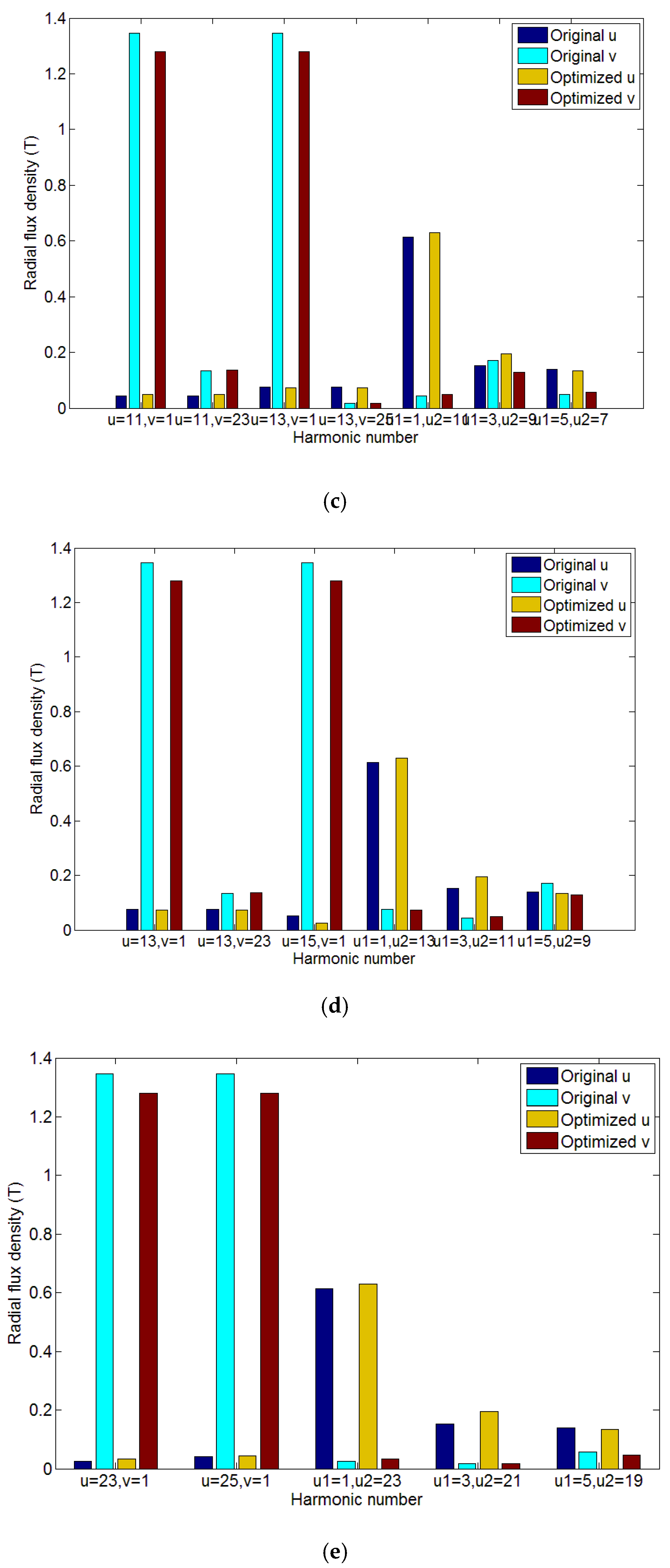
According to the previous theoretical analysis, components of 0th and 6th spatial orders are the main causes of the vibration and noise of this motor. Therefore, we only need to pay attention to the harmonics of the 0th and 6th spatial orders, and the higher order components can be ignored. At the same time, the frequency orders of this motor are integer multiples of 6. The constant component of the radial force density, i.e., components with frequency order 0, is ignored in the figure. Through the analysis of the figure, it can be seen that there is a large amplitude at the frequency order and space order of (6,6), (18,0), (36,0), (42,6), and (72,0) (where (18,0) represents the frequency order of 18 and the spatial order of 0, the same below). So, it may cause large vibration and noise at these frequencies. According to Equation (6), the electromagnetic force are excited by the permanent magnet field and the armature field, so the force harmonics of the above specific orders are due to the interaction of the specific magnetic field harmonics between the permanent magnet and the armature. These harmonics and their interactions are listed in Table 3:
The table lists some interactions of the magnetic field harmonics that produce radial electromagnetic forces of specific frequency orders and spatial orders. As the order increases, the amplitude of the magnetic field harmonic will decreases greatly. Therefore, this paper only focused on the low-order harmonics and ignores the influence of higher-order harmonics.
3.2. Magnetic Field Harmonics Analysis after Rotor Slotting
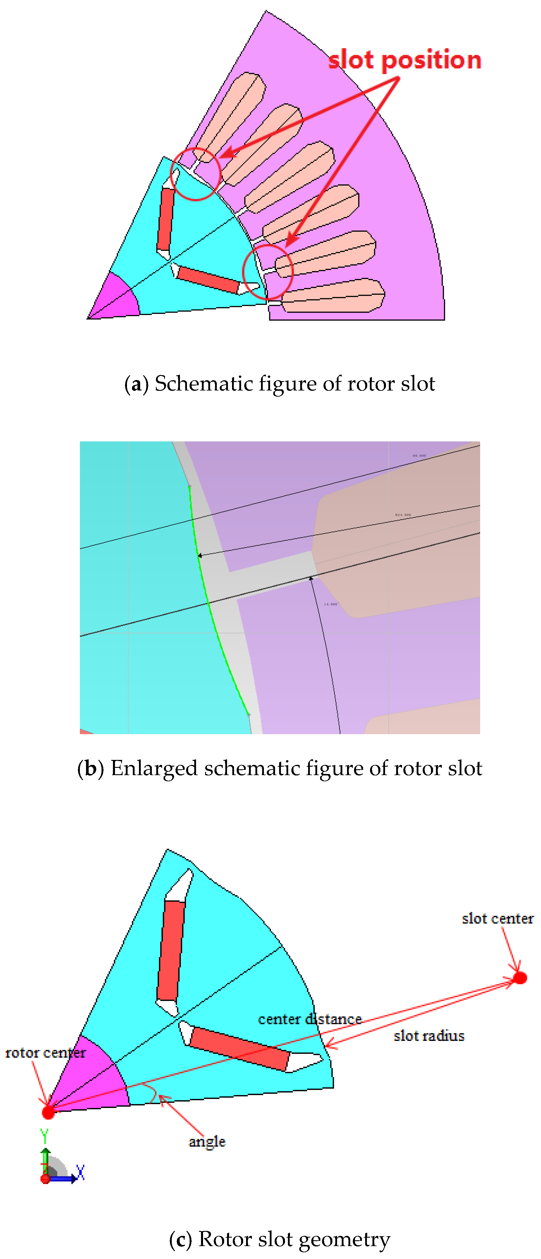
According to the research in [18,19,20], rotor slotting is an effective way to optimize electromagnetic NVH. Then, this paper used the method of rotor slotting to optimize electromagnetic NVH. Firstly, the slotting was performed twice in each unit motor, and then the slotting angle, slotting radius, and center distance were taken as the optimization indicators. The slotting angle optimization step was 0.5 degrees, and the optimization range was 0–30 degrees. The slotting radius optimization step was 0.1 mm, the optimization range was 23–25 mm, the center distance optimization step was 1 mm, and the optimization range was 60–75 mm. Additionally, the amplitudes of the harmonic combinations in Table 3 were used for optimization targets. Multiobjective optimization was performed in the finite element software to obtain a specific optimized position for the rotor slotting. Based on the analysis of the original motor, the rotor was slotted at the specific positions to weaken the specific harmonics of the permanent magnet field and armature field so as to reduce the amplitude of the radial electromagnetic force with orders of (6,6), (18,0), (36,0), (42,6), and (72,0) and to reduce the noise in result. 12 arc-shaped slots were processed on the surface of the rotor. The slot position is shown in Figure 3a,b, and the slot parameters are shown in Table 4.
The center distance in Table 4 is the distance between the center of the rotor and the center of the slot arc, and the angle is the side of unit motor to the center distance line, as shown in Figure 3c.
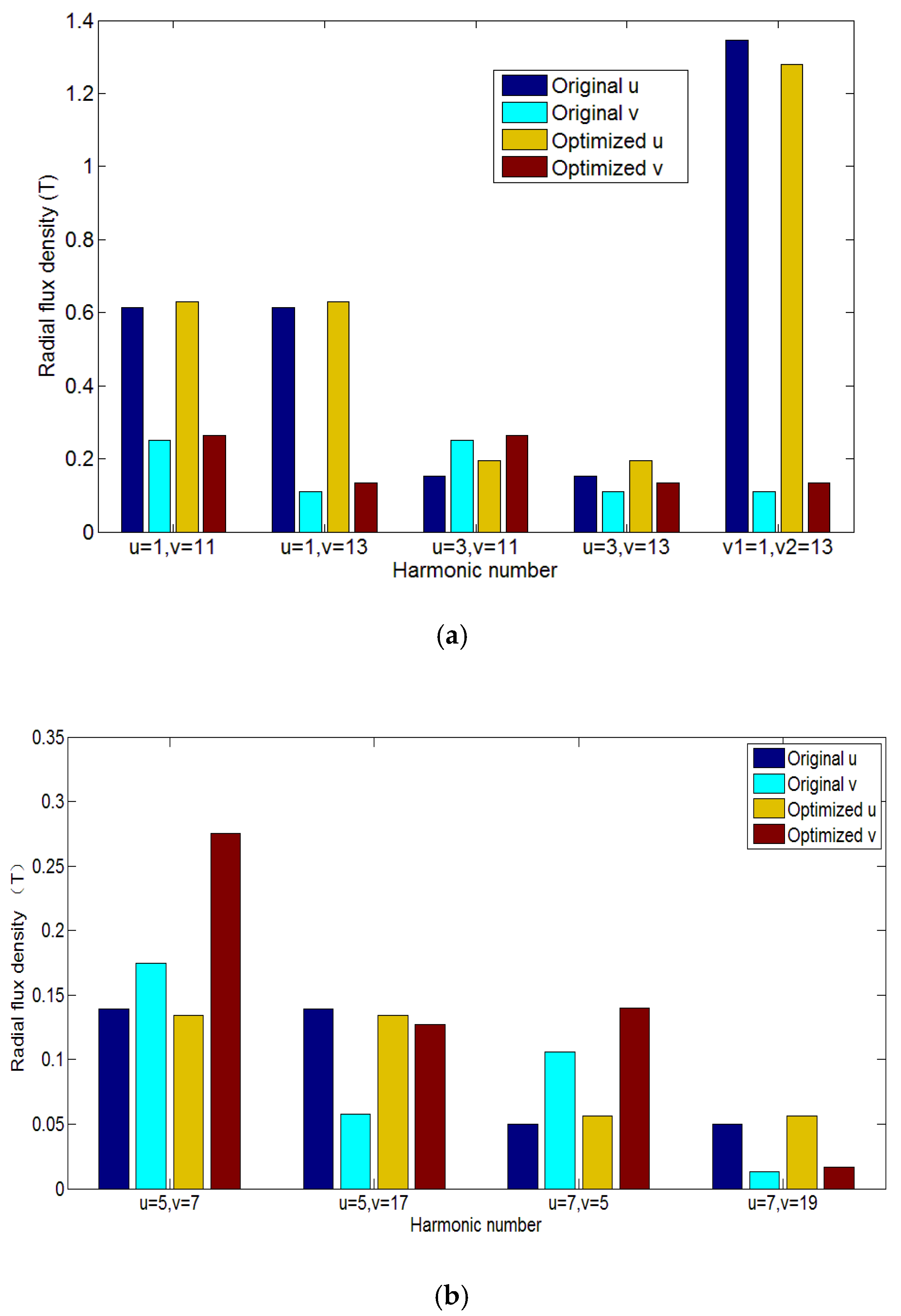
By freezing the relative magnetic permeability, the air gap magnetic density generated by the permanent magnet and the armature was simulated respectively, and the Fourier transform was used to extract the amplitude of the harmonic components of specific orders for further analysis. According to the relations between the electromagnetic force and the magnetic field harmonics in Table 3, the harmonics resulting in electromagnetic force of orders (6,6), (18,0), (36,0), (42,6), and (72,0) were extracted and compared between the original motor and the optimized motor, as shown in Figure 4.
From the analysis of Figure 4, it can be seen that the fundamental amplitude of the radial air gap flux density of the armature field of the motor after rotor slotting decreased compared with the original state, thereby causing the amplitude of the radial force of orders (6,6), (36,0), (42,6), and (72,0) to decrease. Therefore, the radial electromagnetic forces of 6th, 36th, 42th, and 72th frequency orders were reduced, and it is predicted that the noise of these frequencies will decrease. It can be seen from the analysis of Figure 4b that the harmonics of order (18, 0) was not reduced, so it was predicted that the current optimization technique did not improve the noise of frequency order 18.
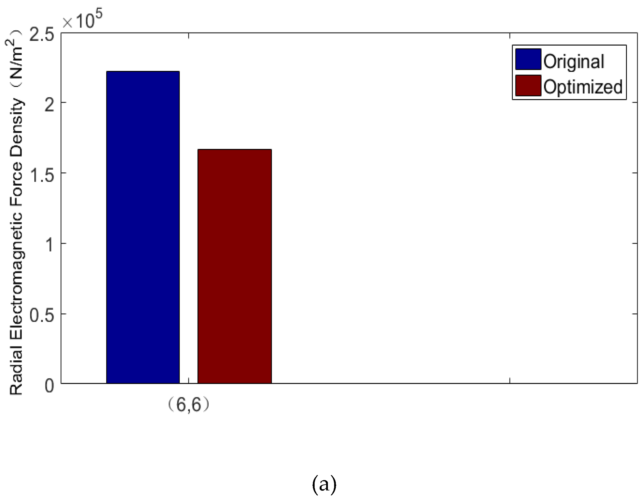
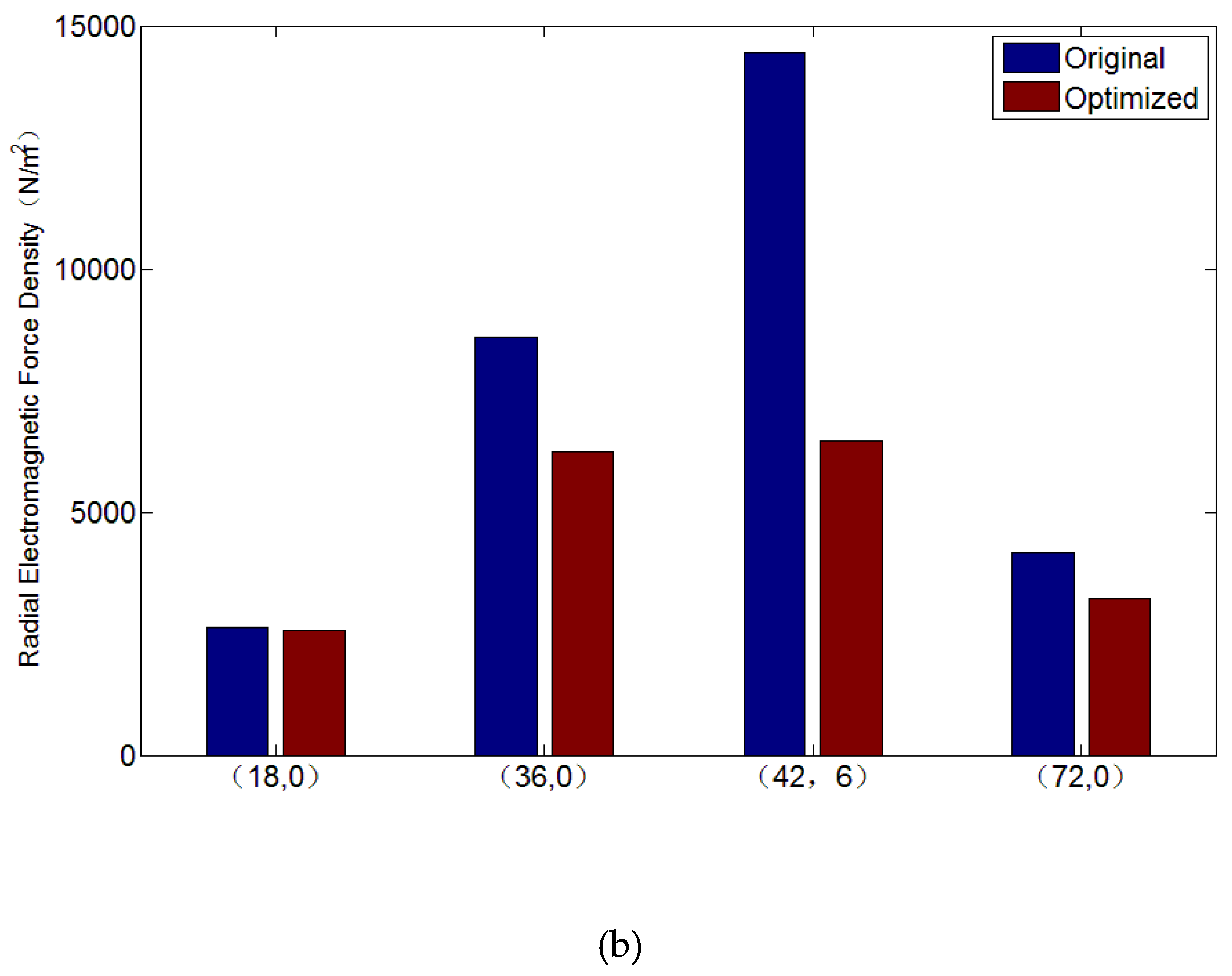
3.3. Comparison of Radial Electromagnetic Force Before and After Rotor Slotting
Figure 5 is a time–space diagram of the radial force density after optimization, and Figure 6b,c are comparisons of amplitude of radial force of orders (6,6), (18,0), (36,0), (42,6), and (72,0) before and after optimization. It can be seen from the figure that the radial electromagnetic forces of orders (6,6), (36,0), (42,6), and (72,0) decrease in varying degree, while the change of order (18,0) was not obvious. In the case that other factors remained unchanged, it could be considered that the vibration and noise of orders (6,6), (36,0), (42,6), and (72,0) were improved, but that of order (18,0) was not significantly improved. Then, the simulation results need to be verified experimentally.
3.4. Tangential Electromagnetic Force Analysis
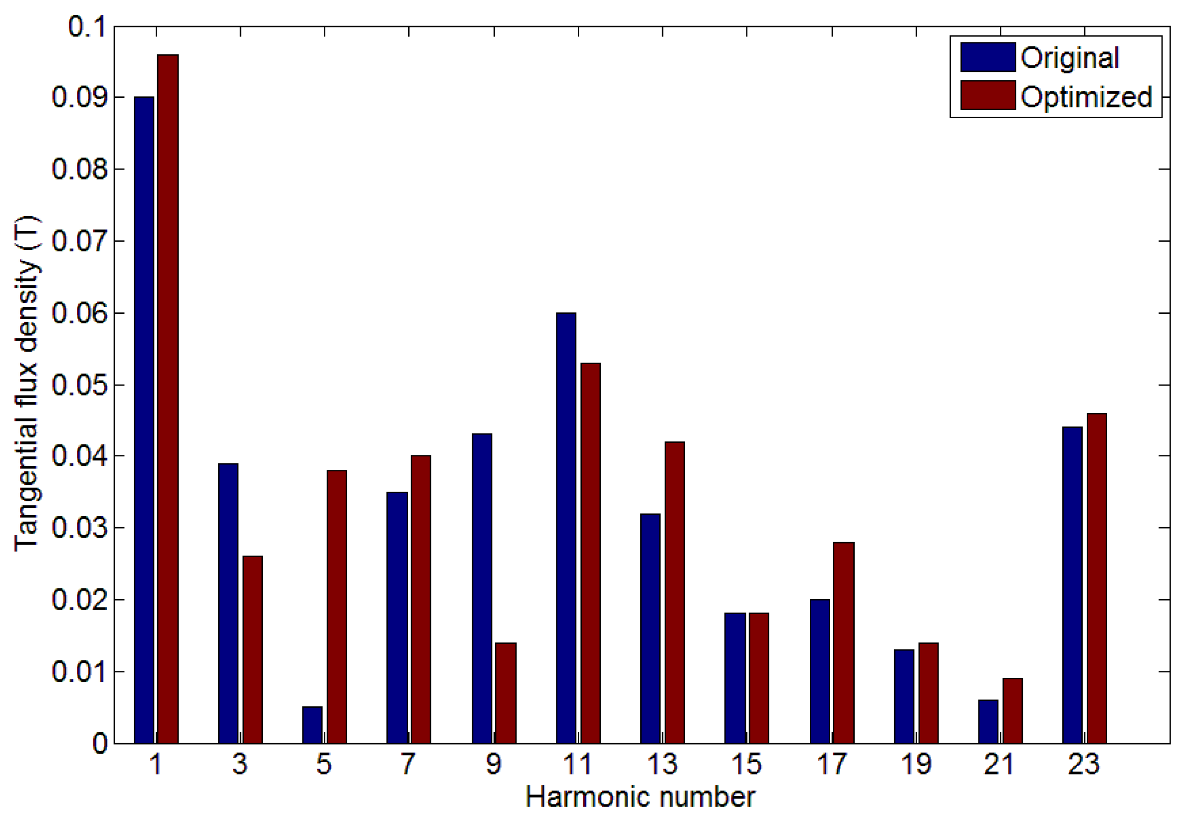
It is well known that the optimization of motor NVH performance should be carried out under the premise of not reducing or slightly reducing the output torque. If the output torque is greatly weakened, then the NVH optimization at this condition is not optimal. The output torque of the motor was generated by the tangential electromagnetic force. Figure 7 shows the comparison of the amplitude of tangential air gap flux density of the motor before and after optimization. It can be seen from the figure that the fundamental amplitude of the tangential air gap flux density increased, and the 3rd, 9th, and 11th harmonics were greatly reduced, thereby reducing the torque ripple. However, since the 5th harmonic increased after rotor slotting, there was still some optimization space in reducing the torque ripple. The output torque of the motor is shown in Table 5. The output torque only decreased by 1.09% after rotor slotting, which had little effect on the power performance of the motor.
4. Test and Verification
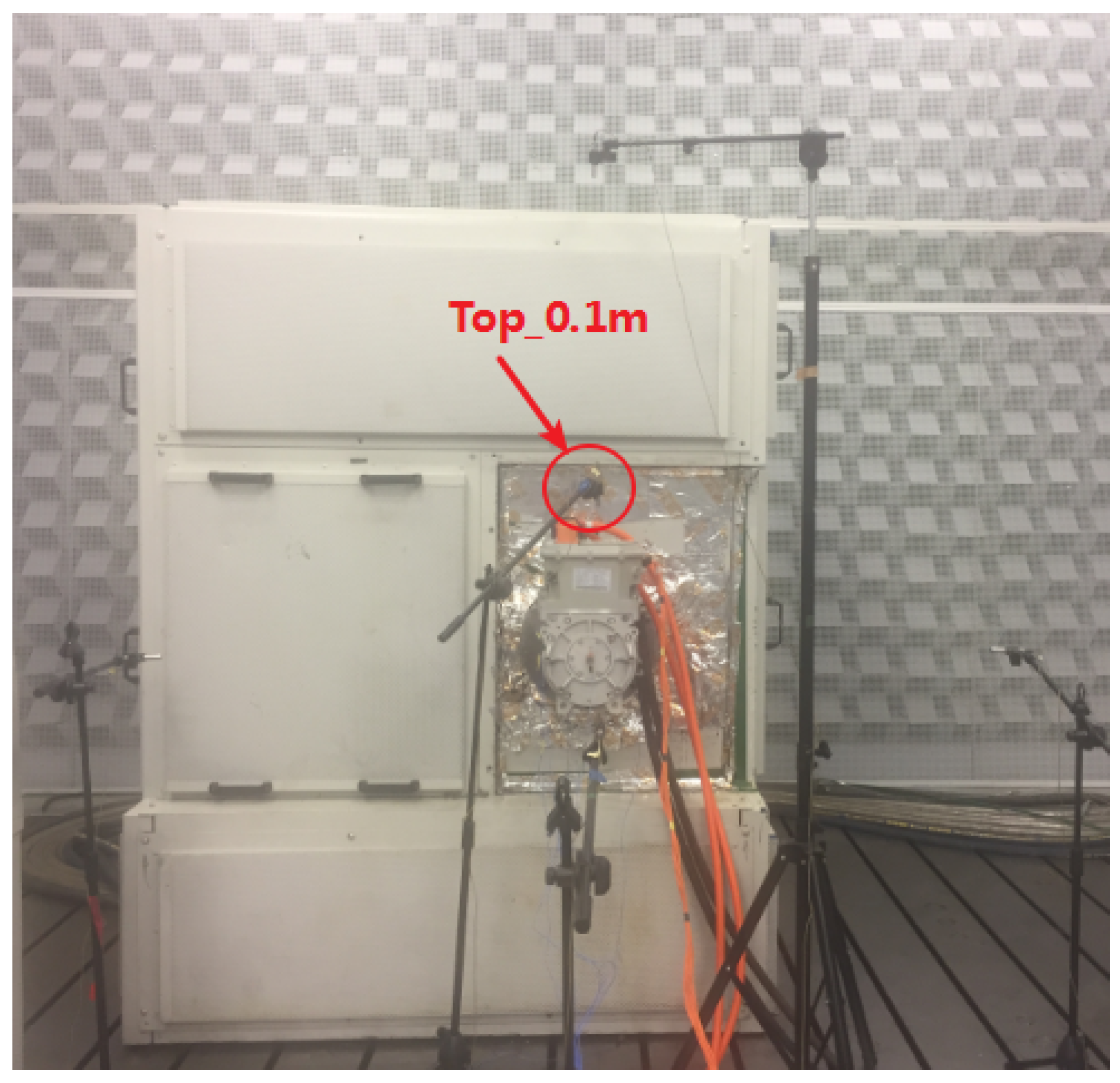
In order to verify the accuracy of theoretical analysis and simulation, the NVH test of the motor was carried out in the semi-anechoic chamber [24], and the motors before and after optimization were tested under the same conditions respectively, and the noise test results were compared. The detailed parameters of the test equipment and test conditions are shown in Table 6 and Table 7. The noise of the motor during operation is measured by a microphone placed 0.1 m above the motor envelope, as shown in Figure 8. The time domain data of the noise of the motor before and after optimization were collected and compared after data processing.
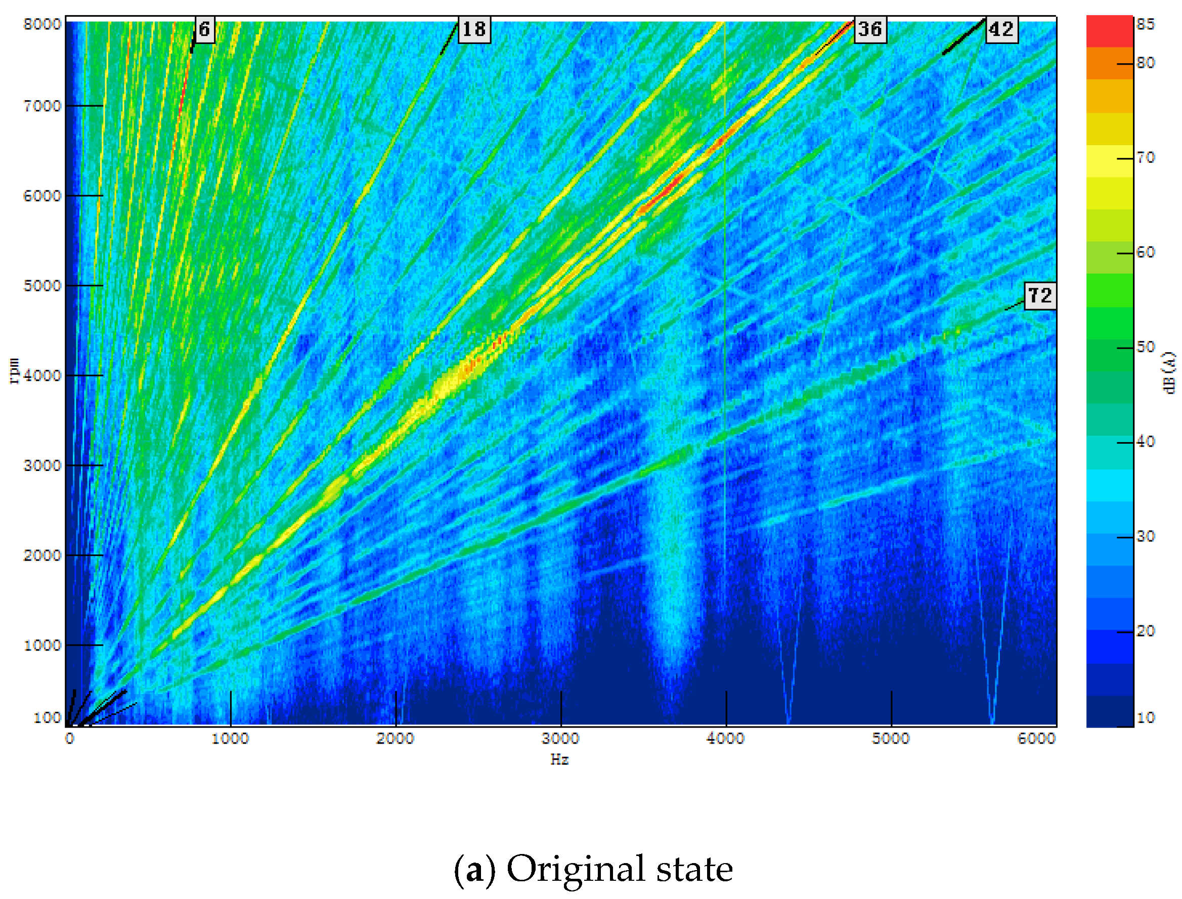
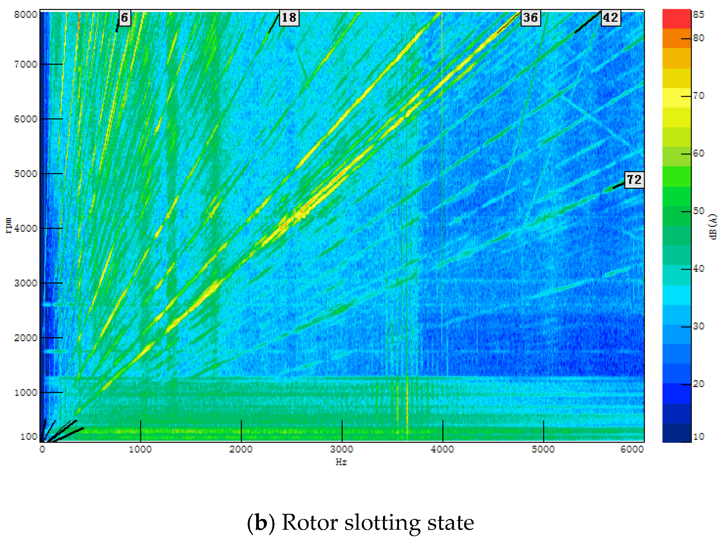
The colormap of the noise test is shown in Figure 9. Figure 9a is the test result of the motor noise in the original state, and Figure 9b is the test result in the rotor slotting state. According to Figure 9, it can be seen from the colormap obtained from the experimental test that during the process of the motor speed increasing from 100 to 8000 rpm, the electromagnetic order noise of the motor was an integer multiple of 6, which was consistent with the previous theoretical analysis results. At the same time, according to the space–time diagrams of the radial force density in Figure 2 and Figure 5, it can be seen that this motor would have NVH problems in the frequency order of 6th, 18th, 36th, 42nd, and 72nd, and both colormaps verify the simulation results. According to comparison of Figure 9a,b, it can be seen that the noise energy of the 6th, 36th, and 72nd frequency order after optimization decrease compared to the original one. The noise of the 18th order did not change much, which was consistent with the simulation results, and the accuracy of theoretical analysis and simulation results was verified. Since the noise of 42nd order was relatively small, the improvement after optimization was not obvious.
By using the rotor slotting method, the 6th, 36th, and 72nd frequency order noise of the motor could be reduced, and the electromagnetic NVH performance was improved. Furthermore, in actual testing, under the premise that other factors were unchanged, reducing the harmonic amplitude by using the method of rotor slotting could indeed effectively reduce the electromagnetic order noise. Additionally, the fast-channel method of electromagnetic NVH optimization proposed in this paper was also verified.
5. Conclusions
(1) Through the theoretical analysis, the frequency order and spatial order of the 6-pole 36-slot PMSM were integer multiples of 6. With simulation analysis, it was found that the motor had a large radial force density amplitude at orders (6,6), (18,0), (36,0), (42,6), and (72,0), which might cause a large electromagnetic vibration and noise.
(2) After decomposing the electromagnetic force of specific orders, it was found that the fundamental amplitude of the radial air gap flux density of the armature reaction field decreased due to the rotor slotting optimization, which weakened the radial electromagnetic force of orders (6,6), (36,0), (42,6), and (72,0). After rotor slotting, the output torque decreased by 1.09%, which had little effect on the power performance of the motor.
(3) The results of the motor NVH test shows that the noise energy of the 6th, 36th, and 72nd frequency order was reduced after rotor slotting, and the 18th order noise changed little, which was consistent with the simulation results. The accuracy of theoretical analysis and simulation results was verified. For the 42nd order noise, the noise energy was very small, and the improvement after optimization was not obvious.
(4) According to conclusion (3), we could draw a conjecture that a large radial electromagnetic force did not necessarily cause significant electromagnetic vibration and noise, but obvious electromagnetic vibration and noise was generally caused by a large radial electromagnetic force. The accuracy of this conjecture would be verified in the future studies.
(5) This paper proposed a new electromagnetic order noise optimization method, that is, under the premise that other factors were unchanged, the harmonics obtained from the mechanism analysis were used as optimization targets, and the rotor slotting was used to weaken these harmonics amplitudes to achieve the purpose of reducing electromagnetic order noise. The method could quickly locate the root cause of electromagnetic NVH and provide a fast channel for electromagnetic NVH optimization from simulation to verification, and improve the optimization efficiency of NVH.
Author Contributions
Y.W. wrote the paper, conceived and designed the analysis; H.G. performed the experiment and collected the data; H.W. contributed to the conception of the study; W.M. helped perform the analysis with constructive discussions. All authors have read and agreed to the published version of the manuscript.
Funding
This research received no external funding.
Acknowledgments
This study is supported by the Natural Science Foundation of Tianjin, China (Grant No.18JCQNJC75000).
Conflicts of Interest
The authors declare no conflict of interest.
Nomenclature
| Notations | Meaning |
| br(θ,t) | the radial air gap flux density |
| fm(θ,t) | the permanent magnet magnetomotive force(MMF) |
| fmo | the radial modal frequency of the motor |
| fn | the radial electromagnetic force frequency |
| fs(θ,t) | the armature MMF |
| Fu | the amplitude of the μth MMF |
| Fv | the amplitude of the υth MMF |
| n | the spatial order of the radial electromagnetic force |
| p | the pole pairs |
| Pr | the radial electromagnetic force amplitude |
| Pr(θ,t) | the radial electromagnetic force density |
| t | time |
| w | the angular velocity |
| Y | the radial vibration amplitude of the motor |
| Z | the number of slots |
| μ | the permanent magnet harmonics |
| υ | the armature harmonics |
| μ0 | air gap magnetic permeability |
| θ | the angular position in the stator steady frame |
| λ(θ,t) | air gap permeance |
| λ0 | the amplitude of the static component of the air gap permeance |
| λi | the amplitude of the ith component of the air gap permeance |
References
- Haodong, Y.; Yangsheng, C. Influence of Radial Force Harmonics with Low Mode Number on Electromagnetic Vibration of PMSM. IEEE Trans. Energy Convers. 2014, 29, 38–45. [Google Scholar]
- Guillaume, V.; Ghias, B.; Yacine, A.; Ghaleb, H. Impact of Pole and Slot Combination on Vibrations and Noise of Electromagnetic Origins in Permanent Magnet Synchronous Motors. IEEE Trans. Magn. 2015, 51, 1–4. [Google Scholar]
- Jacek, F.G.; Chong, W.; Joseph, C.L. Noise of Polyphase Electric Motors; CRC Press: Boca Raton, FL, USA, 2005; ISBN -13: 978-0824723811. [Google Scholar]
- Valavi, M.; Nysveen, A.; Nilssen, R. Influence of Pole and Slot Combinations on Magnetic Forces and Vibration in Low-Speed PM Wind Generators. IEEE Trans. Magn. 2015, 51, 1–10. [Google Scholar] [CrossRef]
- Ziqiang, Z.; Howe, D. Instantaneous magnetic field distribution in brushless permanent magnet DC motors. III: Effect of stator slotting. IEEE Trans. Magn. 1993, 29, 143–151. [Google Scholar]
- Hong-Seok, K.; Kwang-Joon, K. Characterization of noise and vibration sources in interior permanent-magnet brushless DC motors. IEEE Trans. Magn. 2004, 40, 3482–3489. [Google Scholar]
- Lin, F.; Zuo, S.; Deng, W.; Wu, S. Noise Prediction and Sound Quality Analysis of Variable-Speed Permanent Magnet Synchronous Motor. IEEE Trans. Energy Convers. 2017, 32, 698–706. [Google Scholar] [CrossRef]
- Braunisch, D.; Ponick, B.; Bramerdorfer, G. Combined Analytical–Numerical Noise Calculation of Electrical Machines Considering Nonsinusoidal Mode Shapes. IEEE Trans. Magn. 2013, 49, 1407–1415. [Google Scholar] [CrossRef]
- Mostafa, V.; Jean Le, B.; Arne, N. An Investigation of Zeroth-Order Radial Magnetic Forces in Low-Speed Surface-Mounted Permanent Magnet Machines. IEEE Trans. Magn. 2016, 52, 1–6. [Google Scholar]
- Islam, R.; Husain, I. Analytical Model for Predicting Noise and Vibration in Permanent-Magnet Synchronous Motors. IEEE Trans. Ind. Electron. 2010, 46, 2346–2354. [Google Scholar] [CrossRef]
- Lee, S.K.; Kang, G.H.; Jin, H. Finite Element Computation of Magnetic Vibration Sources in 100 kW Two Fractional-Slot Interior Permanent Magnet Machines for Ship. IEEE Trans. Magn. 2012, 48, 867–870. [Google Scholar] [CrossRef]
- Zhu, Z.Q.; Jamil, M.L.M.; Wu, L.J. Influence of Slot and Pole Number Combinations on Unbalanced Magnetic Force in PM Machines with Diametrically Asymmetric Windings. IEEE Trans. Ind. Appl. 2013, 49, 19–30. [Google Scholar] [CrossRef]
- Min, S.G.; Sarlioglu, B. Modeling and Investigation on Electromagnetic Noise in PM Motors with Single and 290 Double Layer Concentrated Winding for EV and HEV Application. IEEE Trans. Ind. Electron. 2018, 4, 292–302. [Google Scholar]
- Fakam, M.; Hecquet, M.; Lanfranchi, V.; Randria, A. Design and Magnetic Noise Reduction of the Surface Permanent Magnet Synchronous Machine Using Complex Air-Gap Permeance. IEEE Trans. Magn. 2015, 51, 1–9. [Google Scholar] [CrossRef] [Green Version]
- Zhu, Z.Q.; Xia, Z.P.; Wu, L.J.; Jewell, G.W. Analytical Modeling and Finite-Element Computation of Radial Vibration Force in Fractional-Slot Permanent-Magnet Brushless Machines. IEEE Trans. Ind. Appl. 2010, 46, 1908–1918. [Google Scholar] [CrossRef]
- Shuguang, Z.; Fu, L.; Xudong, W. Noise Analysis, Calculation, and Reduction of External Rotor Permanent-Magnet Synchronous Motor. IEEE Trans. Ind. Electron. 2015, 62, 6204–6212. [Google Scholar]
- Shuanglong, W.; Shuguang, Z.; Xudong, W. Vibroacoustic Prediction and Mechanism Analysis of Claw Pole Alternators. IEEE Trans. Ind. Electron. 2016, 64, 4463–4473. [Google Scholar]
- Jie, M.; Ziqiang, Z. Unbalanced Magnetic Force Mitigation in 3-slot/2-pole Permanent Magnet Machine by Inserting Auxiliary Slots. In Proceedings of the 2017 IEEE International Electric Machines and Drives Conference (IEMDC), Miami, FL, USA, 21–24 May 2017; pp. 1–8. [Google Scholar]
- Kai, W.; Haiyang, S.; Lufeng, Z.; Chuang, L.; Ziqiang, Z. An Overview of Rotor Pole Optimization Techniques for Permanent Magnet Synchronous Machines. Proc. CSEE 2007, 37, 7304–7318. [Google Scholar]
- Ma, F.; Yin, H.; Wei, L.; Tian, G.; Gao, H. Design and Optimization of IPM Motor Considering Flux Weakening Capability and Vibration for Electric Vehicle Applications. Sustainability 2018, 10, 1533. [Google Scholar] [CrossRef] [Green Version]
- Ma, F.; Yin, H.; Wei, L.; Wu, L.; Gu, C. Analytical Calculation of Armature Reaction Field of the Interior Permanent Magnet Motor. Energies 2018, 11, 2375. [Google Scholar] [CrossRef] [Green Version]
- Chen, Y.; Zhu, Z.; Ying, S. Analysis and Control of Motor Noise; Zhejiang University Press: Hangzhou, China, 1987; pp. 47–51. [Google Scholar]
- Hui, G.; Yongchao, W. Noise Analysis of Permanent Magnet Motors with Different Slot-pole Combinations. Micromotors 2019, 52, 1–4. [Google Scholar]
- Hui, G.; Yongchao, W.; Dong, W. CATARC New Type Drivetrain NVH Test Facility; No. 2019-01-0788; SAE International: Detroit, MI, USA, 2019. [Google Scholar]
Figure 1.
Motor flux density distribution.

Figure 2.
Time–space diagram of the radial force density of the motor in original state.

Figure 3.
Rotor slot position.

Figure 4.
The comparison of air gap flux density harmonic amplitude of orders before and after rotor slotting. (a) Order (6,6); (b) order (18,0); (c) order (36,0); (d) order (42,6); and (e) order (72,0).
Figure 4.
The comparison of air gap flux density harmonic amplitude of orders before and after rotor slotting. (a) Order (6,6); (b) order (18,0); (c) order (36,0); (d) order (42,6); and (e) order (72,0).


Figure 5.
Time–space diagram of the radial force density after the rotor slotting.

Figure 6.
The comparisons of radial force density of orders before and after rotor slotting. (a) Order 6 and (b) order (18,0), (36,0), (42,6), and (72,0).
Figure 6.
The comparisons of radial force density of orders before and after rotor slotting. (a) Order 6 and (b) order (18,0), (36,0), (42,6), and (72,0).


Figure 7.
Comparison of tangential air gap flux density harmonic amplitude.

Figure 8.
Noise test.

Figure 9.
Noise test colormap.


Table 1.
Spatial order and frequency order characteristics of 6-pole 36-slot permanent magnet synchronous motors (PMSM).
Table 1.
Spatial order and frequency order characteristics of 6-pole 36-slot permanent magnet synchronous motors (PMSM).
| Conditions | Spatial Orders | Frequency Orders |
|---|---|---|
| Unload | 0, 6, 12, … | 0, 6, 12, 18, 24, 30, 36, … |
| Full Load | 0, 6, 12, ... | 0, 6, 12, 18, 24, 30, 36, … |
Table 2.
Motor structure parameters.
| Items | Unit | Value |
|---|---|---|
| Number of Rotor Pole | - | 6 |
| Number of Stator Slot | - | 36 |
| Stator Outer Diameter | mm | 179 |
| Stator Inner Diameter | mm | 91.2 |
| Rotor Outer Diameter | mm | 90.3 |
| Rotor Inner Diameter | mm | 26.8 |
| Air Gap Length | mm | 0.45 |
| PM Width | mm | 15.4 |
| PM Thickness | mm | 3.13 |
| PM Material | - | N35 |
| Remanence of PM | T | 1.23 |
| Iron Core Material | - | DW540 |
Table 3.
Magnetic field harmonics that cause specific order electromagnetic force of a 6-pole 36-slot PMSM.
Table 3.
Magnetic field harmonics that cause specific order electromagnetic force of a 6-pole 36-slot PMSM.
| Frequency Orders | Spatial Order | Interactions of Magnetic Field Harmonics |
|---|---|---|
| 6 | 6 | |
| 18 | 0 | |
| 36 | 0 | |
| 42 | 6 | |
| 72 | 0 |
Table 4.
Rotor slot parameters.
| Items | Unit | Value |
|---|---|---|
| Center Distance | mm | 69 |
| Angle | ° | 14.5 |
| Slotting Radius | mm | 24.5 |
Table 5.
Comparison of output torque before and after slotting.
| Original State (Nm/RMS) | Rotor Slotting State (Nm/RMS) | Reduced Percentage (%) |
|---|---|---|
| 94.09 | 93.06 | 1.09 |
Table 6.
Test equipment and environment.
| Items | Unit | Value |
|---|---|---|
| Background Noise | dB(A) | 10 |
| Cut-off Frequency | Hz | 50 |
| Sound Absorption Structure | - | ASA |
| Dynamometer Maximum Power | kW | 220 |
| Dynamometer Maximum Torque | Nm | 450 |
| Dynamometer Maximum Speed | r/min | 10000 |
| Dynamometer Inertia | kg/m2 | 0.05 |
Table 7.
Test conditions.
| Items | Unit | Value |
|---|---|---|
| Speed | r/min | 100–8000 |
| Power | kW | 70 |
| DC Voltage | V | 350 |
| Maximum DC Current | A | 200 |
| Operating Temperature | °C | 60–80 |
© 2020 by the authors. Licensee MDPI, Basel, Switzerland. This article is an open access article distributed under the terms and conditions of the Creative Commons Attribution (CC BY) license (http://creativecommons.org/licenses/by/4.0/).
Share and Cite
MDPI and ACS Style
Wang, Y.; Gao, H.; Wang, H.; Ma, W. NVH Optimization Analysis of Permanent Magnet Synchronous Motor by Rotor Slotting. Vehicles 2020, 2, 287-302. https://0-doi-org.brum.beds.ac.uk/10.3390/vehicles2020016
AMA Style
Wang Y, Gao H, Wang H, Ma W. NVH Optimization Analysis of Permanent Magnet Synchronous Motor by Rotor Slotting. Vehicles. 2020; 2(2):287-302. https://0-doi-org.brum.beds.ac.uk/10.3390/vehicles2020016
Chicago/Turabian StyleWang, Yongchao, Hui Gao, Haiyang Wang, and Wenpeng Ma. 2020. "NVH Optimization Analysis of Permanent Magnet Synchronous Motor by Rotor Slotting" Vehicles 2, no. 2: 287-302. https://0-doi-org.brum.beds.ac.uk/10.3390/vehicles2020016