Article

Electrified Powertrain with Multiple Planetary Gears and Corresponding Energy Management Strategy

1
Autonomous Vehicles & Artificial Intelligence Laboratory (AVAILab), Coventry University, Coventry CV1 5FB, UK
2
Smart Vehicles Control Laboratory (SVeCLab), University of Birmingham, Birmingham B15 2TT, UK
3
FEV Group GmbH, Neuenhofstraße 181, 52078 Aachen, Germany
4
Smart Vehicles Control Laboratory (SVeCLab), University of Sussex, Brighton BN1 9RH, UK
*
Author to whom correspondence should be addressed.
Submission received: 21 May 2021 / Revised: 12 June 2021 / Accepted: 16 June 2021 / Published: 1 July 2021

Abstract

:
Modern hybrid electric vehicles (HEVs) like the fourth generation of Toyota Prius incorporate multiple planetary gears (PG) to interconnect various power components. Previous studies reported that increasing the number of planetary gears from one to two reduces energy consumption. However, these studies did not compare one PG and two PGs topologies at their optimal operation. Moreover, the size of the powertrain components are not the same and hence the source of reduction in energy consumption is not clear. This paper investigates the effect of the number of planetary gears on energy consumption under optimal operation of the powertrain components. The powertrains with one and two PGs are considered and an optimal simultaneous torque distribution and mode selection strategy is proposed. The proposed energy management strategy (EMS) optimally distributes torque demands amongst the power components whilst also controlling clutches (i.e., mode selection). Results show that increasing from one to two PGs reduces energy consumption by 4%.

1. Introduction

Fuel economy improvement is a vital research topic in the automotive industry because of environmental concerns and limited crude oil supplies. According to the vehicle licensing statistics report [1] from the Department of Transport UK, the registered number of Hybrid Electric Vehicles (HEV) in 2020 was 108% higher than that in 2019. Meanwhile, the sale of petrol and diesel vehicles decreased by 8% and 31%, respectively. A hybrid powertrain shows 17% less energy consumption compared to a fully electric and 22% less energy consumption compared to a conventional gasoline powertrain when simulated in a real traffic drive scenario [2,3]. Hybrid electric powertrains with two motors are becoming more popular due to the lower cost of both the electric machines and the drive electronics. Prominent examples are Toyota’s Hybrid Synergy Drive (HSD) [4], Honda’s Intelligent Multi-Mode Drive (iMMD) [5] and General Motors’ Voltec-2 [6].
A key factor in reducing fuel consumption in a hybrid powertrain is its topology, which refers to how the powertrain’s components (i.e., engine, motors and output) are connected with the nodes of the planetary gears (PG). Liu et al. [7] presented an exhaustive search method to analyse all possible topologies for hybrid powertrains with multiple PGs. A 2-PG powertrain has more clutches than a 1-PG powertrain, achieving multimode operation by engaging or disengaging clutches. While Toyota Prius operates in one mode only, Zhang et al. [8] introduced four modes of operation using three clutches. Results show that this reduces fuel consumption from 115.3 g to 96.2 g. In turn, 2-PG-HEV designs incorporated by Toyota Prius and Chevrolet Volt are claimed to provide improved fuel economy compared to their 1-PG counterparts [6,9] for the Federal Urban Drive Cycle (FUDS). In both cases, increasing the number of clutches increases the number of modes.
Studies show that optimal mode selection reduces fuel consumption in HEVs [5,10,11,12]. Up to 12 different topologies are possible in a 1-PG powertrain. By incorporating six clutches, eight modes per topology can be realised. However, 1152 topologies with two modes each are possible for 2-PG powertrains by using only two clutches. Evidently, there is a need for a systematic screening and analysis of modes to identify optimal topology to minimise fuel consumption. The latter is controlled not only by the mode selection but also by the Energy Management Strategy (EMS).
Literature shows that engine and equivalent fuel consumption can be reduced by optimising the EMS. There are different types of energy management strategies used in HEVs, such as rule-based [13,14], instantaneous optimisation-based [15,16,17,18,19], learning-based EMS [20] and predictive EMS [21,22]. A gap in these strategies is that they do not incorporate mode selection because it leads to a challenging mixed-integer nonlinear optimisation problem. Moreover, these strategies have sequential mode selection and torque distribution, which does not guarantee optimal torque distribution among powertrain components. To address these issues, we propose a simultaneous torque distribution and mode selection strategy. The proposed strategy is classified under instantaneous optimisation-based EMS.
Every energy management strategy reported in the literature is optimised for a specific topology with either one or two PGs. In addition, mode selection is not considered in conjunction with EMS in any of the previous studies. To compare two different topologies, an EMS with simultaneous mode selection is important because torque distribution changes with mode. The torque distribution between components caused by mode change affects the operation of components. Therefore, for optimal operation of powertrain components and comparison between different topologies, EMS considering mode selection is required.
While the above-mentioned studies investigate the performance of the electrified powertrains with multiple PGs in a fixed topology, the effects of the number of PGs on the fuel consumption and battery SoC are not addressed. Furthermore, the electrified powertrains in those investigations have different component sizes depending on whether they are within a one- or two-PG architecture. The contributions of this paper are as follows:
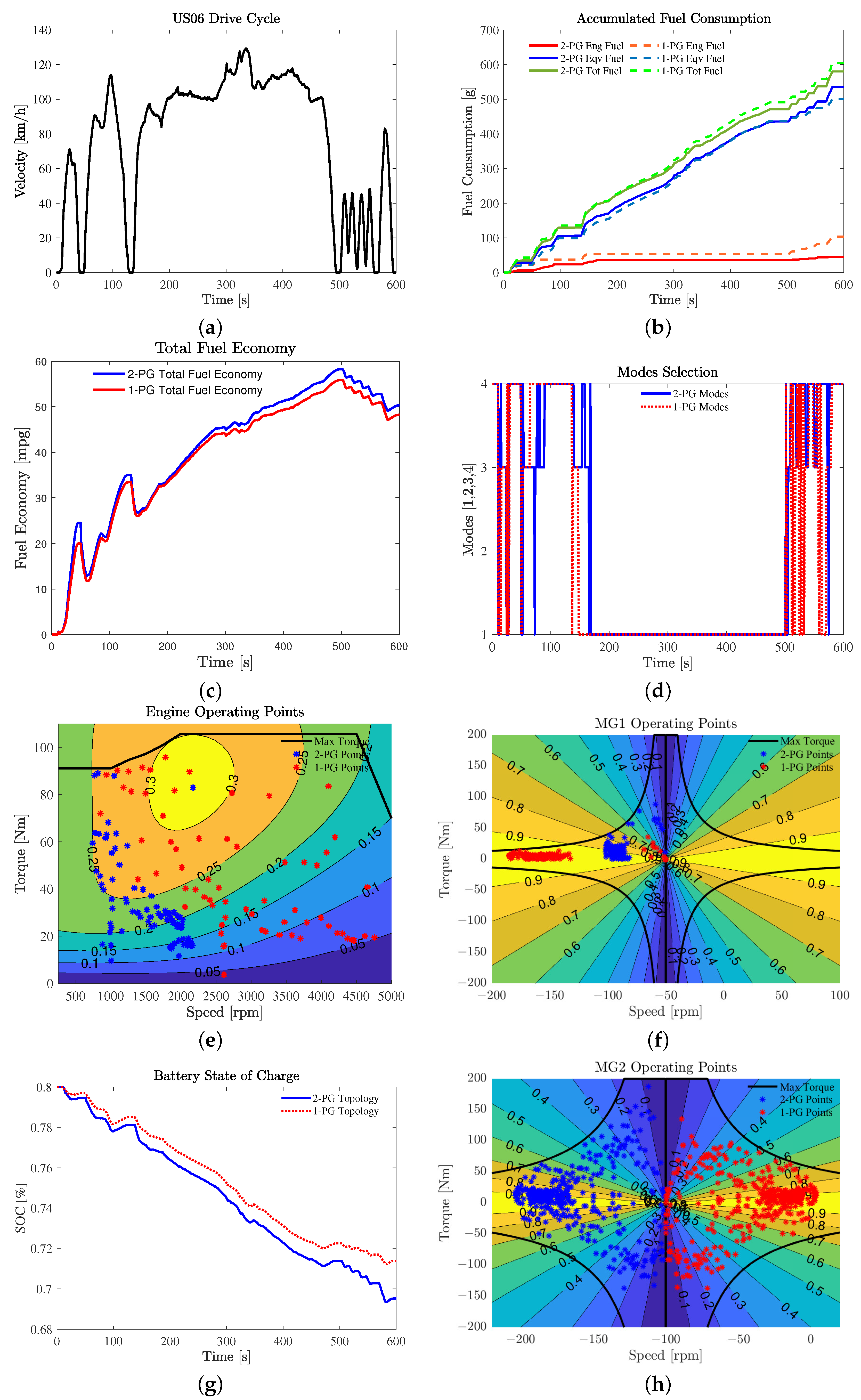
  • Comprehensive investigation of the effects of multiple PGs on the performance of the electrified vehicles. It is shown that increasing the number of PGs from one to two improves fuel economy by 4%.
  • Development of an optimal EMS for the electrified powertrains with multiple PGs, to distribute torque demands amongst power components, as well as to simultaneously select the mode of operation of gearbox.
  • Development of a solver for the resulting mixed-integer EMS using NEOS server.
The remainder of the paper is organised as follows: The system description is presented in Section 2; the modes for the drivetrain with one and two PGs are described in Section 3, whilst an energy management strategy (EMS) with embedded mode selection is proposed in Section 4; simulation results and discussions are provided in Section 5 and conclusions are presented in Section 6.

2. System Description

The powertrain components used in this study are adapted from ASM hybrid model of dSPACE. dSPACE is the simulation software that can perform hardware in loop (HIL) and software in loop (SIL) simulations, and it is available in the AVAILab of Coventry University. The values of component sizes are tabulated in Table 1.

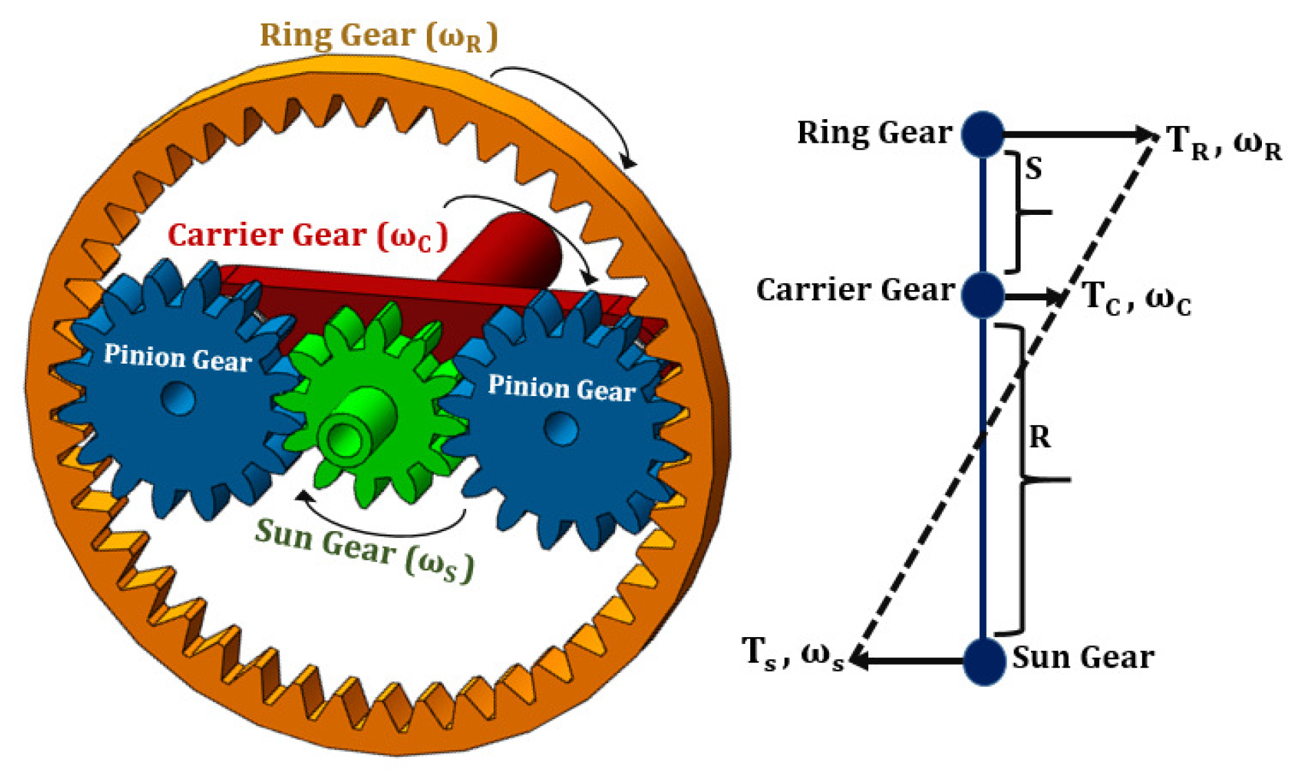
2.1. Planetary Gearbox

Planetary gearbox is the main gearbox of the hybrid powertrain and may contain one or more planetary gears. A PG consists of the sun gear, the ring gear and the carrier gear with several pinions. Lever analogy [23] is used to demonstrate the dynamics of 1-PG powertrain, as shown in Figure 1. The angular velocities of sun gear, ring gear and carrier gear must satisfy the constraint equation given in Equation (1) [23].
ω S + ω R = ω C ( R + S )
In this work, only 1-PG and 2-PG topologies are considered. The 1-PG topology used here has Motor Generator 1 (MG1) connected to the sun gear, Motor Generator 2 (MG2) connected to the ring gear and the engine connected to the carrier gear.
The 1-PG topology with four clutches [8] is shown in Figure 2. Depending on the clutch engagements, four modes can be generated, which are described in Table 2.
In the 2-PG topology, MG1 is connected to the sun gear of the first PG ( S 1 ), MG2 is connected to the sun gear of the second PG ( S 2 ) and the engine is connected to the carrier gear of the first PG ( C 1 ). The 2-PG topology with five clutches [8] is shown in Figure 3. All four modes generated by engaging and disengaging clutches are similar to those of the 1-PG topology.
Four different modes of operation are described in Table 2. Mode 1 ( M 1 ) refers to 2EV Mode, where both MG1 and MG2 provide the torque requested by the vehicle. Mode 2 ( M 2 ) refers to series mode, where MG2 provides the torque requested by the vehicle while engine and MG1 charge the battery. Mode 3 ( M 3 ) refers to input split mode, where MG2 and engine provide the torque requested by the vehicle while MG1 acts as a speed controller for the engine. Mode 4 ( M 4 ) refers to 1EV mode, where only MG2 provides torque.

2.2. Electric Motors

Motor Generator 1 (MG1) is the smaller of the two motors in the powertrain with a capacity of 42 kW. The maximum speed and maximum torque of MG1 are ±30,000 rpm and ±200 Nm, respectively. MG1 is attached to the sun gear in the 1-PG topology ( S 1 ) and to the sun gear of the first PG in the 2-PG topology ( S 1 ). MG1 not only contributes to providing the torque requested in Mode 1 but also acts as a speed controller for the engine in Mode 3. The efficiency of MG1 is calculated as in Equation (2).
η m g 1 k = 1 1 + T m g 1 k C T m g 1 2 R m g 1 T m g 1 k ω m g 1 k
Motor Generator 2 (MG2) is the motor having a capacity of 60 kW. The maximum speed and maximum torque of MG2 are ±15,000 rpm and ±200 Nm, respectively. In 1-PG topology, both MG2 and the differential are connected to the ring gear ( R 1 ). In 2-PG topology, MG2 is connected to the sun gear ( S 2 ) whilst the differential is connected to the ring gear ( R 2 ) of the second PG. The efficiency of MG2 is calculated as in Equation (3).
η m g 2 k = 1 1 + T m g 2 k C T m g 2 2 R m g 2 T m g 2 k ω m g 2 k

2.3. Engine

A gasoline engine with a maximum power of 50 kW and a maximum torque at 2000 rpm of 105 Nm is used for both topologies. The engine is connected to the carrier gear of the first PG ( C 1 ). The fuel flow rate of the engine ( q k ) is measured in mm 3 /cycle and modelled using a 5-degree polynomial as a function of engine torque and angular velocity (see Appendix A). The efficiency of engine is calculated as in Equation (4).
η b t h k = π T e k ρ q k Q H H V

2.4. Battery

A battery with a capacity of 27 kWh is used to operate both MG1 and MG2 in this study. The battery’s state-of-charge (SoC) is calculated as shown in Equation (5).
S o C k + 1 = S o C k T k P b a t t k 3600 · 27000
This equation shows that the SoC in the next time-step depends on the SoC in the current time-step and on battery power. In turn, the latter is a function of torque, angular velocity and efficiency of MG1 and MG2. Battery power is given by Equations (6)–(8) during motoring and by Equation (9) during regeneration.
P b a t t k = T m g 2 k ω m g 2 k η m g 2 k 1 + T m g 1 ω m g 1 η mg 1 k 1 M 1 , k
P b a t t k = T m g 2 k ω mg 2 k η m g 2 k 1 + T m g 1 ω m g 1 η m g 1 k + 1 M 2 , k
P b a t t k = T m g 2 k ω m g 2 k η m g 2 k 1 M i , k , i { 3 , 4 }
P b a t t k = T m g 2 k ω m g 2 k η m g 2 k + 1 M i , k , i { 1 , 2 , 3 , 4 }
Both MG1 and MG2 are used for motoring in Mode 1 whereas only MG2 is used for motoring in Modes 2–4. Regeneration is only performed by MG2. MG1 is also used as generator for charging the battery in series mode, which is referred to as Mode 2.

3. Modes for the Drivetrain with Multiple Planetary Gears

Modes formulation for 1-PG and 2-PG topologies can be represented by automated mode selection process [8]. Using four clutches in 1-PG topology and five clutches in 2-PG topology, four different modes are realised. The torque, angular velocity, inertia and output corresponding to each component in every mode are shown in the equations below.

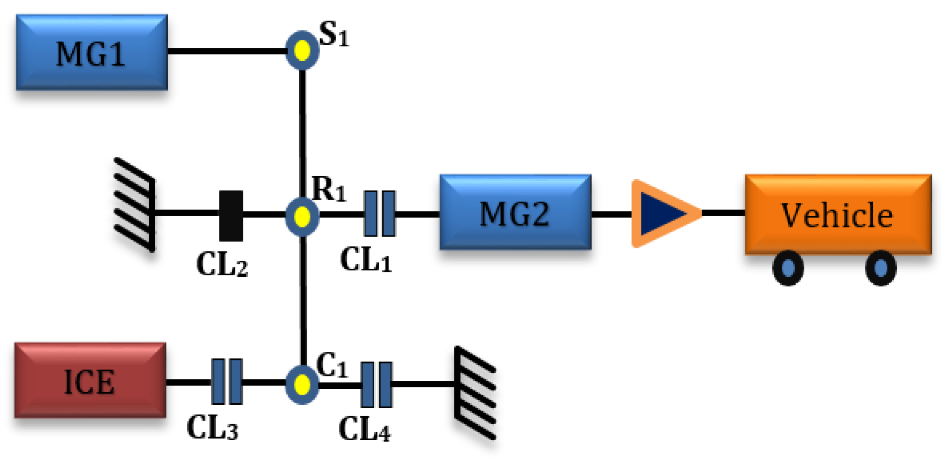
3.1. Drivetrain with 1PG

For the drivetrain with 1-PG topology, MG2 connects to the ring gear ( R 1 ), MG1 connects to the sun gear ( S 1 ) and the engine connects to the carrier gear ( C 1 ). The 1-PG topology with four clutches [8] is shown in Figure 2, where four different modes can be produced according to the clutch engagements. The governing equations corresponding to all modes for the 1-PG topology are as follows:
  • Mode 1 (2EV Mode) is realised by engaging clutch 1 (CL 1 ) and CL 4 whilst disengaging CL 2 and CL 3 . Using automated modelling, the mode dynamics for Mode 1 is as shown in Equation (10).
    m r t y r e 2 K 2 + I m g 2 0 R 1 0 I m g 1 S 1 R 1 S 1 0 × ω ˙ o u t ω ˙ m g 1 F 1 = T m g 2 T r e q T m g 1 0
  • Mode 2 (Series Mode) is realised by engaging CL 1 , CL 2 and CL 3 whilst disengaging CL 4 . The mode dynamics for Mode 2 is as shown in Equations (11) and (12).
    I e 0 R 1 + S 1 0 I m g 1 S 1 R 1 + S 1 S 1 0 × ω ˙ e ω ˙ m g 1 F 1 = T e T m g 1 0
    m r t y r e 2 K 2 + I m g 2 ω ˙ o u t = T m g 2 T r e q
  • Mode 3 (Input Split Mode) is realised by engaging CL 1 and CL 3 whilst disengaging CL 2 and CL 4 . The mode dynamics for Mode 3 is as shown in Equation (13).
    I e 0 0 R 1 + S 1 0 m r t y r e 2 K 2 + I m g 2 0 R 1 0 0 I m g 1 S 1 R 1 + S 1 R 1 S 1 0 × ω ˙ e ω ˙ o u t ω ˙ m g 1 F 1 = T e T m g 2 T r e q T m g 1 0
  • Mode 4 (1EV Mode) is realised by engaging CL 1 and CL 4 whilst disengaging CL 2 and CL 3 . In this mode, only MG2 is engaged to the differential via CL1, and therefore a simple equation can represent the mode dynamics as shown in Equation (14).
    m r t y r e 2 K 2 + I m g 2 ω ˙ o u t = T m g 2 T r e q

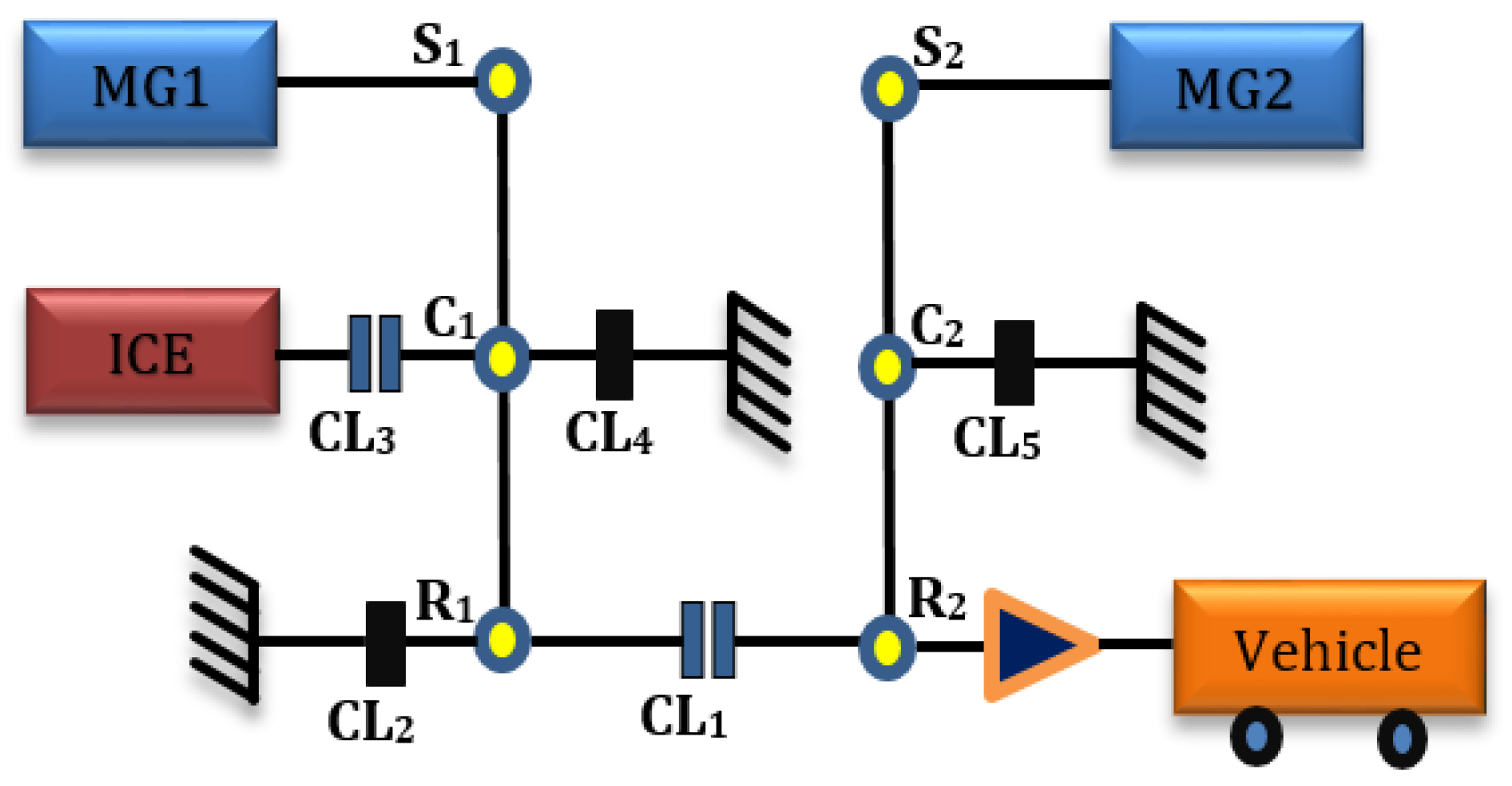
3.2. Drivetrain with 2PG

For the drivetrain with 2-PG topology, MG2 connects to the sun gear of the second PG ( S 2 ), MG1 connects to the sun gear of the first PG ( S 1 ), whilst the engine connects to the carrier gear of the second PG ( C 2 ). The 2-PG topology with five clutches [8] is shown in Figure 3, where four different modes can be produced according to the clutch engagements (similar to the 1-PG topology modes). The governing equations corresponding to all modes for the 2-PG topology are as follows:
  • Mode 1 (2EV Mode) is realised by engaging CL 1 , CL 2 , CL 4 , CL 5 whilst disengaging CL 3 . The mode dynamics for Mode 1 is as shown in Equation (15).
    I o u t + I R 1 0 0 R 1 R 2 0 I m g 1 0 S 1 0 0 0 I m g 2 0 S 2 R 1 S 1 0 0 0 R 2 0 S 2 0 0 × ω ˙ o u t ω ˙ m g 1 ω ˙ m g 2 F 1 F 2 = T r e q T m g 1 T m g 2 0 0
  • Mode 2 (Series Mode) is realised by engaging CL 2 , CL 3 and CL 5 whilst disengaging CL 1 and CL 4 . The mode dynamics for Mode 2 is as shown in Equations (16) and (17).
    I e 0 R 1 + S 1 0 I m g 1 S 1 R 1 + S 1 S 1 0 × ω ˙ e ω ˙ m g 1 F 1 = T e T m g 1 0
    I o u t 0 0 R 2 0 I m g 2 0 S 2 0 0 0 0 R 2 S 2 0 0 × ω ˙ o u t ω ˙ m g 2 F 1 F 2 = T r e q T m g 2 0 0
  • Mode 3 (Input Split Mode) is realised by engaging CL 1 , CL 3 and CL 5 and disengaging CL 2 and CL 4 . The mode dynamics for Mode 3 is as shown in Equation (18).
    I o u t + I R 1 0 0 0 R 1 R 2 0 I e 0 0 R 1 + S 1 0 0 0 I m g 1 0 S 1 0 0 0 0 I m g 2 0 S 2 R 1 R 1 + S 1 S 1 0 0 0 R 2 0 0 S 2 0 0 × ω ˙ o u t ω ˙ e ω ˙ m g 1 ω ˙ m g 2 F 1 F 2 = T r e q T e T m g 1 T m g 2 0 0
  • Mode 4 (1EV Mode) is realised by disengaging and engaging CL 2 , CL 4 & CL 5 and disengaging CL 1 & CL 3 . The mode dynamics for Mode 4 is as shown in Equation (19).
    I o u t 0 0 R 2 0 I m g 2 0 S 2 0 0 0 0 R 2 S 2 0 0 × ω ˙ o u t ω ˙ m g 2 F 1 F 2 = T r e q T m g 2 0 0

4. Energy Management Strategy with Mode Selection

In this study, the performances of drivetrains with 1-PG and 2-PG topologies are compared. For a meaningful comparison between topologies, they must be operating at their optimal performance. Since modes have an impact on the performance of powertrain components, it is crucial that the EMS selects modes and torque distribution simultaneously. Therefore, the energy management strategy (EMS) proposed in this work considers both mode selection and torque distribution simultaneously.
Developing an EMS with mode selection is a difficult optimisation problem because of mixed-integer variables and discontinuity in mode selection within a continuous drive cycle. In addition, the torque distribution is different for every mode, adding nonconvexity to the system. Complementarity is used to formulate mode selection to address discontinuity within the modes.

4.1. EMS Formulation

The energy management strategy is a multistage problem discretised with a sampling time of 1 s for the US06 drive cycle. The objectives of the EMS are to minimise total fuel consumption, mode shifting and deviation of battery SoC. The problem is turned into a single-objective optimisation problem by means of a convex combination of these objectives. The decision variables are the engine torque, MG2 torque, angular velocity of MG1, modes and α : u = [ T e , T m g 2 , ω m g 1 , M 1 , M 2 , M 3 , M 4 , α ] T . Binary variable α represents the states of the motor, with α = 0 during regeneration and α = 1 during motoring. The battery SoC is a differential state variable: x = [ S o C ] . The optimisation problem is formulated so that it provides a locally optimal solution for any SoC value used at the start of the cycle. The algebraic variables of the problem are MG1 torque, MG2 angular velocity and engine angular velocity: z = [ T m g 1 , ω m g 2 , ω e ] T .

4.1.1. Objective Function

As mentioned before, the objective function consists of a convex combination of three objectives, as shown in Equation (20). The first two objectives are total fuel consumption ( m ˙ t k ) and a mode shift penalty ( s ˙ k ). The third objective is given by a penalty for battery SoC deviation between the start and the end of the cycle. The weights for the SoC and mode shift penalties in the convex combination are set to small values so that total fuel consumption dominates the objective function.
J = k = 0 600 T s 0.5 m ˙ t k + 0.1 s ˙ k + 0.4 ( 0.8 S o C k ) 2
m ˙ t k = m ˙ i c e k + m ˙ e q v k
m ˙ i c e k = q ρ ω e k 120
m ˙ e q v k = T m g 2 k ω m g 2 k η m g 2 k η b a t t c h a r η b a t t d i s c h a r 1 0.35 1 Q H H V M 4 , k α k T m g 2 k ω m g 2 k η m g 2 k η b a t t c h a r η b a t t d i s c h a r 1 η b t h k 1 Q H H V M 3 , k α k T mg 2 k ω m g 2 k η m g 2 k η b a t t c h a r η b a t t d i s c h a r 1 η b t h k 1 Q H H V M 2 , k α k T m g 2 k ω m g 2 k η m g 2 k + T m g 1 k ω m g 1 k η m g 1 k η b a t t c h a r η b a t t d i s c h a r 1 0.35 1 Q H H V M 1 , k α k
s ˙ k = 1 2 δ γ I e ω e k ω e k 1 2 + I m g 1 ω m g 1 k ω m g 1 k 1 2
Equation (24) computes the mode shift penalty at every time interval k, where γ is a weighting factor fixed to 0.02 [11]. The mode state related factor δ = 0 if the next and current modes are the same, whilst δ = 1 otherwise. The mode shift penalty is necessary to avoid an excessive number of mode shifts. This is a key term which represents the rotational kinetic energy change in the hybrid system. Frequent mode shift also leads to mechanical losses due to recurrent engagement and disengagement of clutches.

4.1.2. Constraints

The constraints in Equations (25) and (26) show the distribution of torque at every mode for 1-PG topology and 2-PG topologies respectively. Constraints in Equation (27) show complementarity between modes. The EMS can choose only one mode at any time-step (k), which will change the torque distribution between components.
T m g 1 k = S 1 R 1 T m g 2 k α k + T r e q k D G R M 1 , k
T m g 1 k = S 1 T e k R 1 + S 1 M 2 , k
ω M G 1 k = R 1 S 1 ω M G 2 k M 1 , k α k
T m g 2 k = T r e q k D G R M i , k , i { 2 , 4 }
T m g 2 k = R 1 T e k R 1 + S 1 α k + T r e q k D G R M 3 , k
ω m g 2 k = D G R V v e h k r t y r e M i , k , i { 1 , 2 , 3 , 4 }
ω e k = ω m g 1 k 1 + R 1 S 1 + ω mg 2 k 1 + S 1 R 1 M 3 , k α k
ω e k = ω m g 1 k 1 + R 1 S 1 M 2 , k
T m g 1 k = S 1 R 1 R 2 S 2 T M G 2 k α k + T r e q k D G R M 1 , k
T m g 1 k = S 1 T e k R 1 + S 1 M 2 , k
ω mg 1 k = S 2 S 1 ω m g 2 k M 1 , k α k
T m g 2 k = S 2 R 2 T r e q k D G R M i , k , i { 2 , 4 }
T m g 2 k = S 2 R 2 R 1 T e k R 1 + S 1 α k + T r e q k D G R M 3 , k
ω m g 2 k = D G R V v e h k r t y r e R 2 S 2 M i , k , i { 1 , 2 , 3 , 4 }
ω e k = ω m g 1 k S 1 R 1 + S 1 ω mg 2 k S 2 R 1 + S 1 M 3 , k α k
ω e k = ω m g 1 k 1 + R 1 S 1 M 2 , k
0 < = M 4 , k M 1 , k > = 0 0 < = M 4 , k M 2 , k > = 0 0 < = M 4 , k M 3 , k > = 0 0 < = M 3 , k M 1 , k > = 0 0 < = M 2 , k M 3 , k > = 0 0 < = M 2 , k M 1 , k > = 0 M 1 , k + M 2 , k + M 3 , k + M 4 , k = 1

4.1.3. Optimal Control Problem of the Developed EMS

The optimal control problems of the developed EMS strategies for the both 1-PG and 2-PG topologies are represented as Equation (28). The two problems are similar except in modelling of the gears. While the 1-PG topology is modelled with Equations (25) and (27), the 2-PG topology is modelled using Equations (26) and (27). In both cases, the objective function is the same and decision variables, differential state variable and algebraic variables are constrained by their lower and upper boundaries (boxing constraints).
u * = arg min u k = 0 600 T s l ( x , u , k ) s . t . : ( 25 ) ( or ( 26 ) ) , ( 27 ) u ̲ u u ¯ x ̲ x x ¯ z ̲ z z ¯ M 1 , M 2 , M 3 , M 4 , α { 0 , 1 }

5. Simulation Results and Discussion

A Mathematical Programming Language (AMPL) [24] is used to formulate the EMS optimisation problem. AMPL was designed as a mathematical modelling language for linear programming but was later extended to integer, mixed-integer linear, mixed-integer nonlinear and complementarity problems [25]. There are significant advantages of modelling optimisation problems with AMPL thanks to its symbolic representation. This includes the possibility of automated analysis of model parts for linearity, convexity, automatic differentiation, extended error checking, and automatic generation of model code for lower-level languages [26].
Problem (28) is a Mixed Integer Non-Linear Programming (MINLP), which means it is also nonconvex. Due to mixed integers and nonconvexity, it becomes difficult to get a locally optimal solution. To address these issues Knitro solver is used for solving the optimisation problem. Knitro is a commercially used solver which is developed by Richard et al. [27]. It uses Branch and Bound (BB) technique to solve problems with discrete variables. Knitro also have inbuilt solvers like Sequential Quadratic Programming (SQP), Linear Programming (LP) and Non-Linear Programming (NLP) to solve continuous variables. NEOS server [28,29] is used to access Knitro solver for solving the optimisation problem. Figure 4 summarises simulation results of the 1-PG and 2-PG topologies over the US06 drive cycle in Figure 4a.
The total fuel consumption of the powertrain with two PGs drops by 4% compared to 1-PG topology from 604.6 g to 579.8 g, as shown in Figure 4b. The total fuel consumption is the sum of the direct fuel consumption by engine and the equivalent fuel consumption by electric drivetrains. Equivalently, Figure 4c also shows that the total fuel economy of the 2-PG topology is 50.28 mpg which is higher than 48.22 mpg of the 1-PG topology.
The main reason for the lower fuel consumption of the 2-PG topology is that the corresponding EMS uses the engine at lower speed than in 1-PG, resulting in a decrease in direct fuel consumption as given in Figure 4b. This particularly happens during the time intervals of 0–180 s and 500–600 s, when the EMS configures the powertrain frequently for Mode 3 as shown in Figure 4d. During Mode 3, both the MG2 and engine contributes to the torque at wheels, and MG1 only restrains the speed of engine within the optimal range to reduce bsfc. From Equations (25h) and (26h), it is evident that for 2-PG topology, the speed of the engine relates to the difference of speeds of MG1 and MG2, while it is the weighted sum of these two speeds for the 1-PG topology. Therefore, and as shown in Figure 4e, EMS of the 2-PG topology can choose a high value for the speed of MG1 as a decision variable to reduce the speed of engine. EMS of the 1-PG-topology, on the other hand, should reduce the speed of MG1 at high vehicle speeds to reduce the speed of engine; however, the latter still increases to up to 5000 rpm by high vehicle speed. As a result, the speed and hence power of the engine becomes lower in the 2-PG topology at Mode 3 that is applied when the torque demand is high.
The equivalent fuel consumption of 2-PG topology is 535.16 g, which is higher than 501.29 g of 1PG topology (Figure 4b). The amount of fuel required by engine to generate the equivalent electrical energy that motors consume from battery is referred to as equivalent fuel consumption. The reason for this increase in equivalent fuel consumption is that MG1 operates at higher torque and lower speed range in 2-PG topology during Mode 1, as shown in Figure 4f. This behaviour is explained by the constraints Equation (25a) and Equation (26a), where the torque provided by MG1 in the 2-PG topology is R 2 S 2 = 2.63 times higher than the torque provided by MG1 in the 1-PG topology.
Figure 4d shows that the optimal mode selection strategies, calculated by the EMSs, are different for the 1-PG and 2-PG topologies. The EMS of both the topologies selects Mode 1 during the time interval of 180 s to 500 s. Mode 1 refers to 2EV mode, where both MG1 and MG2 contribute to the torque provided at the wheels of the vehicle. During this time interval, torque demand is not high but vehicle speed fluctuates frequently.
During the time intervals of 0–180 s and 500–600 s of the drive cycle, on the other hand, torque demand is high with sharp variation of the vehicle speed. In response, EMSs choose Modes 1 as well as 3 and 4. As mentioned, 2-PG topology provides the flexibility of using the engine at lower speed that makes EMS more eager to choose the combination of Modes 3 and 4 instead of Mode 1. Switching between modes should be minimum because turning the engine on and off between Modes 3 and 1 increases fuel consumption. Moreover, engaging and disengaging the clutches to produce different modes contributes to the mechanical losses. Equation (24) represents the way that the EMSs penalise the number of mode shifting. Total number of the mode switch over the US06 drive cycle is 1.5% less in 2-PG topology compared to 1-PG topology.
Figure 4g illustrates variation of the state of charge (SoC) of batteries. The final SoC of batteries are respectively 71.38% and 69.53% for the 1-PG and 2-PG topologies. This complies with Figure 4b that illustrates higher utilisation of the electric drivetrain by the 2-PG rather than 1-PG topology.
Figure 4h presents the resulting operating points of MG2, which has a significant impact on the total fuel consumption of the topologies as the main source of power in Modes 1, 3 and 4. The main difference between the operation of MG2 in the 1-PG and 2-PG topologies is in the direction of rotation, as in Figure 4h. Figure 5a,b illustrate this fact with more details. Moreover, Figure 5c,d indicate the details of the torques contributed by different components. This change of direction of rotation of MG2 makes reduction of engine speed in Mode 3 possible, as discussed before.
Table 3 summarises the simulation results of fuel consumption, final value of SoC and tracking error of torque for the 1-PG and 2-PG topology over US06 driving cycle. As explained above and summarised in the table, the 2-PG topology improves the total fuel consumption, as well as the torque tracking error, i.e., the difference between the desired and supplied torques at wheels. This tracking error is due to the limitations of the state-of-the-art numerical solvers for the mixed-integer optimal control problems. The simulation results show that these limitations induce the majority of tracking errors during Mode 1, where the solvers relax the equality constraints (25) and (26). As shown in Figure 4d, the 1-PG topology operates in Mode 1 more frequently, which introduces more tracking error.

6. Conclusions

This work proposes a systematic method to understand the effects of multiple planetary gears on the performance and fuel economy of hybrid electric vehicles. A hybrid powertrain with two PGs and one with a single PG were modelled over a US06 drive cycle, while all remaining powertrain components were maintained the same. The proposed EMS is capable of simultaneously selecting modes and distributing torques over a given drive cycle for the optimal performance. The resulting MINLP problem is solved using Knitro solver. It is important to note that the proposed strategy is applicable to any drive cycle.
The proposed EMS minimises (i) total fuel consumption calculated adding engine fuel consumption and equivalent fuel consumption of the electric machines, (ii) mode shifting and (iii) deviation of battery SoC. The EMS considers mode selection and torque demand distribution simultaneously amongst the powertrain components. The incorporation of mode selection challenged the EMS by adding mixed-integer variables, discontinuity within a continuous drive cycle and nonconvexity. Complementarity addressed the discontinuity in mode selection and the problem was turned into single-objective optimisation by means of a convex combination of the three objectives. A solver was also developed using NEOS server.
Results show that increasing the number of PGs from one to two reduces total fuel consumption by 4%. The main reason of the reduction in total fuel consumption of the 2-PG is the capability to change the direction of rotation of MG2. This ability enabled the corresponding optimal EMS to use the engine at more efficient rotational speeds than in the case of 1-PG. The flexibility of using the engine at lower speed makes the EMS eager to choose the combination of Modes 3 (input split) and 4 (1EV) instead of switching to Mode 1 (2EV). The reduction in the total number of mode switches (1.5% over the drive cycle) in 2-PG topology compared to 1-PG topology decreased the mechanical losses associated to mode switch. Therefore, the most efficiency engine operation, the reduction of mode switch and the higher utilisation of the electric drivetrain are the major contributors to the reduction in total fuel consumption in 2-PG with respect to 1-PG topology.
The methodology developed can be extended to any hybrid electric powertrain topologies/architectures and to any number of planetary gears. It should be noted, however, that the added cost of a more complex topology was not considered in this study.

Author Contributions

Original draft written by D.R.; conceptualization carried out by D.R. and A.M.D.; methodology done by D.R. and A.M.D.; investigation, D.R., J.M.H., M.S.I., A.M.D.; formal analysis D.R., J.M.H., M.S.I., J.S., A.M.D.; resources by M.S.I. and J.S.; funding acquisition J.M.H., M.S.I., A.M.D.; supervision by J.M.H., M.S.I., J.S., A.M.D.; writing-review and editing by D.R., J.M.H., M.S.I., J.S., A.M.D.; project administration D.R. and A.M.D.; software D.R. and A.M.D. All authors have read and agreed to the published version of the manuscript.

Funding

This research was co-funded by Coventry University and FEV Europe GmbH.

Institutional Review Board Statement

Not applicable.

Informed Consent Statement

Not applicable.

Conflicts of Interest

The authors declare no conflict of interest.

Abbreviations

r t y r e Radius of tyre
m i c e Engine fuel consumption
b s f c Brake specific fuel consumption
m e q v Equivalent fuel consumption
m t Total fuel consumption
ω R Angular velocity of ring gear
ω S Angular velocity of sun gear
ω C Angular velocity of carrier gear
ω o u t Angular velocity of output shaft
T m g 1 Torque of motor generator 1
T m g 2 Torque of motor generator 2
T e Torque of engine
η m g 1 Efficiency of motor generator 1
η m g 2 Efficiency of motor generator 2
η b t h Brake thermal efficiency of engine
T r e q Torque requested by vehicle
mMass of vehicle
C T m g 2 Torque constant MG2
C T m g 1 Torque constant MG1
R m g 2 MG2 Resistance
R m g 1 MG1 Resistance
P b a t t Battery power
M i Mode i
I * Inertia of powertrain components
ω * Angular velocity of powertrain components
R i Radius of ring gear of i-PG Topology
S i Radius of sun gear of i-PG Topology
F i Internal force acting between gears of i-PG Topology
S o C State of charge
kTime interval (1 s)
qFuel flow rate of engine
ρ Density of gasoline
Q HHV Calorific value of gasoline
α Motor states −1 for motoring and 0 for regeneration

Appendix A. Deriving an Equation for Mass Flow Rate per Cycle of Fuel of Engine

The mass of fuel from engine is calculated by Equation (22). The variable q used in that equation refers to mass flow rate of fuel per cycle. Using dSPACE engine dynamics model, q is derived as 5-degree polynomial equation which is the function of engine torque (T e ) and engine speed ( ω e ). The equation of q is as follows:
q = p 00 + p 10 ω e k + p 01 T e k + p 20 ω e k 2 + p 11 ω e k T e k + p 02 T e k 2 + p 30 ω e k 3 + p 21 ω e k 2 T e k + p 12 ω e k T e k 2 + p 03 T e k 3 + p 40 ω e k 4 + p 31 ω e k 3 T e k + p 22 ω e k 2 T e k 2 + p 13 ω e k T e k 3 + p 04 T e k 4 + p 50 ω e k 5 + p 41 ω e k 4 T e k + p 32 ω e k 3 T e k 2 + p 23 ω e k 2 T e k 3 + p 14 ω e k T e k 4 + p 05 ω e k 5
p 00 = 9.888 × 10 1 p 10 = 3.087 × 10 4 p 02 = 9.858 × 10 3 p 30 = 2.739 × 10 11 p 21 = 1.265 × 10 8 p 12 = 3.348 × 10 7 p 13 = 1.059 × 10 11 p 04 = 1.742 × 10 6 p 50 = 7.724 × 10 19 p 41 = 8.884 × 10 18 p 32 = 4.498 × 10 15 p 23 = 1.147 × 10 13 p 14 = 2.844 × 10 12 p 05 = 5.227 × 10 9 p 01 = 5.154 × 10 2 p 20 = 4.332 × 10 8 p 11 = 5.215 × 10 5 p 03 = 2.006 × 10 4 p 40 = 9.107 × 10 15 p 31 = 9.222 × 10 13 p 22 = 8.382 × 10 11

References

  1. Thomas Parry, S.R. Vehicle Licensing Statistics: 2020 Quarter 3 (Jul-Sep); Department of Transport: London, UK, 2020. [Google Scholar]
  2. Wegener, M.; Plum, T.; Eisenbarth, M.; Andert, J. Energy saving potentials of modern powertrains utilizing predictive driving algorithms in different traffic scenarios. J. Automob. Eng. 2020, 234, 992–1005. [Google Scholar] [CrossRef]
  3. Eisenbarth, M.; Wegener, M.; Scheer, R.; Andert, J.; Buse, D.S.; Klingler, F.; Sommer, C.; Dressler, F.; Reinold, P.; Gries, R. Toward Smart Vehicle-to-Everything Connected Powertrains: Driving real component test benches in a fully interactive virtual smart city. IEEE Veh. Technol. Mag. 2020, 16, 75–82. [Google Scholar] [CrossRef]
  4. Sieg, C.; Küçükay, F. Benchmarking of Dedicated Hybrid Transmissions. Vehicles 2020, 2, 100–125. [Google Scholar] [CrossRef] [Green Version]
  5. Chen, X.; Jiang, J.; Zheng, L.; Tang, H.; Chen, X. Study and Analysis of a Multi-Mode Power Split Hybrid Transmission. World Electr. Veh. J. 2020, 11, 46. [Google Scholar] [CrossRef]
  6. Duhon, A.N.; Sevel, K.S.; Tarnowsky, S.A.; Savagian, P.J. Chevrolet Volt Electric Utilization. SAE Int. J. Altern. Powertrains 2015, 4, 269–276. [Google Scholar] [CrossRef]
  7. Liu, J.; Peng, H. A systematic design approach for two planetary gear split hybrid vehicles. Veh. Syst. Dyn. 2010, 48, 1395–1412. [Google Scholar] [CrossRef]
  8. Zhang, X.; Li, S.E.; Peng, H.; Sun, J. Efficient Exhaustive Search of Power-Split Hybrid Powertrains With Multiple Planetary Gears and Clutches. J. Dyn. Syst. Meas. Control. 2015, 137. [Google Scholar] [CrossRef]
  9. Conlon, B.M.; Blohm, T.; Harpster, M.; Holmes, A.; Palardy, M.; Tarnowsky, S.; Zhou, L. The Next Generation “Voltec” Extended Range EV Propulsion System. SAE Int. J. Altern. Powertrains 2015, 4, 248–259. [Google Scholar] [CrossRef]
  10. Zhang, X.; Peng, H.; Sun, J. A near-optimal power management strategy for rapid component sizing of multimode power split hybrid vehicles. IEEE Trans. Control. Syst. Technol. 2015, 23, 609–618. [Google Scholar] [CrossRef]
  11. Zhuang, W.; Zhang, X.; Li, D.; Wang, L.; Yin, G. Mode shift map design and integrated energy management control of a multi-mode hybrid electric vehicle. Appl. Energy 2017, 204, 476–488. [Google Scholar] [CrossRef]
  12. Anselma, P.G.; Huo, Y.; Amin, E.; Roeleveld, J.; Emadi, A.; Belingardi, G. Mode-shifting Minimization in a Power Management Strategy for Rapid Component Sizing of Multimode Power Split Hybrid Vehicles. SAE Tech. Pap. Ser. SAE Int. 2018. [Google Scholar] [CrossRef] [Green Version]
  13. Sorrentino, M.; Rizzo, G.; Arsie, I. Analysis of a rule-based control strategy for on-board energy management of series hybrid vehicles. Control. Eng. Pract. 2011, 19, 1433–1441. [Google Scholar] [CrossRef]
  14. Liang, J.; Zhang, J.; Zhang, H.; Yin, C. Fuzzy Energy Management Optimization for a Parallel Hybrid Electric Vehicle using Chaotic Non-dominated sorting Genetic Algorithm. Automatika 2015, 56, 149–163. [Google Scholar] [CrossRef] [Green Version]
  15. Gupta, V. ECMS based hybrid algorithm for energy management in parallel hybrid electric vehicles. HCTL Open Int. J. Technol. Innov. Res. (IJTIR) 2015, 14, 1814–2321. [Google Scholar]
  16. Paganelli, G.; Delprat, S.; Guerra, T.M.; Rimaux, J.; Santin, J.J. Equivalent consumption minimization strategy for parallel hybrid powertrains. In Proceedings of the Vehicular Technology Conference. IEEE 55th Vehicular Technology Conference, VTC Spring 2002 (Cat. No. 02CH37367), Birmingham, AL, USA, 6–9 May 2002; Volume 4, pp. 2076–2081. [Google Scholar]
  17. Paganelli, G.; Tateno, M.; Brahma, A.; Rizzoni, G.; Guezennec, Y. Control development for a hybrid-electric sport-utility vehicle: Strategy, implementation and field test results (I). In Proceedings of the American Control Conference, Arlington, VA, USA, 25–27 June 2001; Volume 2, p. 5064. [Google Scholar]
  18. Brahma, A.; Guezennec, Y.; Rizzoni, G. Optimal energy management in series hybrid electric vehicles. In Proceedings of the 2000 American Control Conference. ACC (IEEE Cat. No.00CH36334), Chicago, IL, USA, 28–30 June 2000. [Google Scholar] [CrossRef]
  19. Zhang, Y.; Chu, L.; Fu, Z.; Guo, C.; Zhao, D.; Li, Y.; Ou, Y.; Xu, L. An improved adaptive equivalent consumption minimization strategy for parallel plug-in hybrid electric vehicle. Proc. Inst. Mech. Eng. Part D J. Automob. Eng. 2018, 233, 1649–1663. [Google Scholar] [CrossRef]
  20. Hu, Y.; Li, W.; Xu, K.; Zahid, T.; Qin, F.; Li, C. Energy Management Strategy for a Hybrid Electric Vehicle Based on Deep Reinforcement Learning. Appl. Sci. 2018, 8, 187. [Google Scholar] [CrossRef] [Green Version]
  21. Zhang, S.; Xiong, R.; Sun, F. Model predictive control for power management in a plug-in hybrid electric vehicle with a hybrid energy storage system. Appl. Energy 2017, 185, 1654–1662. [Google Scholar] [CrossRef]
  22. Zhang, F.; Wang, L.; Coskun, S.; Pang, H.; Cui, Y.; Xi, J. Energy Management Strategies for Hybrid Electric Vehicles: Review, Classification, Comparison, and Outlook. Energies 2020, 13, 3352. [Google Scholar] [CrossRef]
  23. Benford, H.L.; Leising, M.B. The Lever Analogy: A New Tool in Transmission Analysis. SAE Tech. Pap. Ser. SAE Int. 1981. [Google Scholar] [CrossRef]
  24. Fourer, R.; Gay, D.M.; Kernighan, B.W. AMPL: A Modeling Language for Mathematical Programming; Cengage Learning: Boston, MA, USA, 2002. [Google Scholar]
  25. Biegler, L.T. Nonlinear Programming; Society for Industrial and Applied Mathematics: Philadelphia, PA, USA, 2010. [Google Scholar] [CrossRef]
  26. Gay David, M. Hooking your Solver to Ampl; Computing Sciences Research Center Bell Laboratories: Murray Hill, NJ, USA, 1997. [Google Scholar]
  27. Byrd, R.H.; Jorge, N.; Richard, A.W. Knitro: An integrated package for nonlinear optimization. In Large Scale Nonlinear Optimization; Springer: Boston, MA, USA, 2006; Volume 35. [Google Scholar]
  28. Dolan, E.D.; Fourer, R.; Goux, J.P.; Munson, T.S.; Sarich, J. Kestrel: An Interface from Optimization Modeling Systems to the NEOS Server. Informs J. Comput. 2008, 20, 525–538. [Google Scholar] [CrossRef] [Green Version]
  29. Czyzyk, J.; Mesnier, M.P.; More, J.J. The NEOS Server. IEEE Comput. Sci. Eng. 1998, 5, 68–75. [Google Scholar] [CrossRef]
Figure 1. Three-dimensional representation of a planetary gearbox with its lever analogy.
Vehicles 03 00021 g001
Figure 2. Topology of the drivetrain with one planetary gear used in this study.
Vehicles 03 00021 g002
Figure 3. Topology of the drivetrain with two planetary gears used in this study.
Vehicles 03 00021 g003
Figure 4. Simulation results for (a) US06 drive cycle, (b) Engine, equivalent, and total fuel consumption, (c) Total fuel economy, (d) Mode selection as given in Table 2, (e) Operating points of engine, (f) Operating points of MG1, (g) Battery state of charge for 1-PG and 2-PG topology, (h) Operating points of MG2.
Vehicles 03 00021 g004
Figure 5. Simulation results for (a) Angular velocities of each component at each mode for 1-PG topology, (b) Angular velocities of each component at each mode for 2-PG topology, (c) Torque distribution at each mode for 1-PG topology, (d) Torque distribution at each mode for 2-PG topology.
Vehicles 03 00021 g005
Table 1. Sizes of the powertrain components.
Component NameParameters (Maximum Values)
Internal Combustion Engine (ICE)50 kW at 4500 rpm, 105 Nm at 2000 rpm
Motor Generator 2 (MG2)60 kW, ± 200  Nm, ±13,000 rpm
Motor Generator 1 (MG1)42 kW, ± 200  Nm, ±30,000 rpm
Battery27 kWh
PG1 (R 1 :S 1 )2:6
PG2 (R 1 :S 1 )2:6
PG2 (R 2 :S 2 )2:63
Differential Gear Ratio(D G R )3.95
Vehicle Mass (m)1450 kg
Tyre Radius (r t y r e )0.33 m
Table 2. Different modes of operation for 1-PG and 2-PG topologies.
ModeRepresented asMode Classification
1M 1 2EV Mode
2M 2 Series Mode
3M 3 Input Split Mode
4M 4 1EV Mode
Table 3. Summary of simulation results of the 1-PG and 2-PG topologies over the US06.
Description1-PG Topology Values2-PG Topology Values
Total Engine Fuel Consumption103.3 g44.9 g
Total Equivalent Fuel Consumption501.3 g535.2 g
Total Fuel Consumption604.6 g579.8 g
Total Fuel Economy48.2 mpg50.3 mpg
Battery SoC at the end of cycle71.4%69.5%
Torque Tracking error13.2 Nm11.4 Nm
Publisher’s Note: MDPI stays neutral with regard to jurisdictional claims in published maps and institutional affiliations.

