Review

Effect of Components and Operating Conditions on the Performance of PEM Electrolyzers: A Review

Department of Chemical Engineering, University of Waterloo, Waterloo, ON N2L 3G1, Canada
*
Authors to whom correspondence should be addressed.
Submission received: 5 August 2022 / Revised: 8 September 2022 / Accepted: 13 September 2022 / Published: 23 September 2022
(This article belongs to the Collection Feature Papers in Electrochemistry)

Abstract

:
Hydrogen is considered to be the fuel of the future and with the advancement of fuel cell technology, there is a renewed interest in hydrogen production by the electrolysis of water. Among low-temperature water electrolysis options, polymer electrolyte membrane (PEM) electrolyzer is the preferred choice due to its compact size, intermittent use, and connectivity with renewable energy. In addition, it is possible to generate compressed hydrogen directly in the PEM electrolyzer, thereby reducing the additional pressurization cost for hydrogen storage. The development of electrocatalysts for oxygen evolution reaction (OER) and hydrogen evolution reaction (HER) is a major focus of electrolysis research. Other components, such as PEMs, gas diffusion layers (GDL), and bipolar plates (BPs) have also received significant attention to enhance the overall efficiency of PEM electrolyzers. Improvements in each component or process of the PEM electrolyzer have a significant impact on increasing the energy efficiency of the electrolyzer. This work discusses various synthesis techniques to improve the dispersion of OER electrocatalyst and reducing catalyst loading for the PEM electrolyzer. Various techniques are discussed for the development of electrocatalysts, including nanostructured, core shell, and electrodeposition to deposit catalysts on GDL. The design and methodology of new and improved GDL are discussed along with the fabrication of gas diffusion electrodes and passivation techniques to reduce the oxidation of GDL. The passivation technique of BPs using Au and Pt is summarized for its effect on electrolysis efficiency. Finally, the optimization of various operating conditions for PEM electrolyzer are reviewed to improve the efficiency of the electrolyzer.

1. Introduction

Hydrogen is an energy-dense and clean fuel and provides 140 MJ/Kg upon oxidation, and its only byproduct is water [1]. Hydrogen is mainly produced by steam methane reforming, which can produce high-pressure hydrogen along with CO and CO2 [2]. Hydrogen is predominantly used in making NH3 by the Haber–Bosch process, which is then used for making urea (fertilizer) [3]. In addition, hydrogen is used extensively in petrochemical processes and petroleum refining. Steam methane reforming is not a renewable route to obtain hydrogen, and thus water electrolysis is the most sought-after route to obtain clean and renewable hydrogen. Climate change is also linked to the burning of fossil fuels and greenhouse gases, so obtaining hydrogen from renewable sources will also decrease the effects of global warming [4]. The energy source for the electrolysis must be from a renewable source, such as from wind turbines and photo voltaic cells to obtain CO2-free H2 from the electrolysis. This hydrogen can be utilized for transportation purposes, such as in fuel-cell-powered vehicles.
PEM water electrolysis is the most efficient and practical technology for producing renewable hydrogen with high purity [5,6]. There is renewed interest in hydrogen production from water by utilizing renewable energy sources and by application of new technologies in catalysis and material science. PEM electrolyzer has many advantages compared with other electrolysis methods; the biggest advantages are the formation of high-purity hydrogen, a small carbon footprint and compact design, the application of higher current density on the electrodes and a high-pressure operation up to 200 bar [7]. The high-pressure operation allows the hydrogen to be delivered and used at high pressure and minimizes the extra cost of pressurization. These are the reasons that PEM electrolyzers are the preferred choice for producing high-purity hydrogen [8,9,10].
A PEM electrolyzer consists of a catalyst-coated membrane (CCM) that is fabricated by spraying the catalyst on the ion-exchange resin membrane. The perfluorosulfonic acid (PFSA) membranes are usually used in PEM electrolyzers due to their high conductivity and stability in a corrosive environment. The CCM is sandwiched between the anode and cathode electrodes. Each catalyst layer is made up of a catalyst layer, gas diffusion layer (GDL) and BPs (Bipolar plates) that transfer gas and liquid in and out of the cell and act as a current collector. Some other configurations are also used in the literature, where the catalyst is coated onto the metal GDL to improve the dispersion of the catalyst and to decrease the passivation of GDL.
Water electrolysis in the PEM electrolyzer involves the splitting of water into hydrogen and oxygen with the application of an electric current [11]. A hydrogen evolution reaction (HER) takes place on the cathode side and an OER (Oxygen Evolution Reaction) takes place at the anode [12,13]. The minimum voltage required across the electrodes to split water is 1.23 V based on a low-heating value, which results in the evolution of hydrogen and oxygen. In a real scenario, this voltage is always higher because of the overpotential at both electrodes [14,15]. To decrease the overpotential, research efforts have been directed at developing catalysts with low overpotential. For half-cell reactions, the OER at the anode is more demanding due to the four-electron process mechanism in the generation of oxygen; on the other hand, the HER is comparatively less demanding than the OER and has a relatively lower overpotential [16,17].
Gas diffusion layers (GDL) are an important part of the PEM electrolyzer; they control the diffusion of water into the catalyst layer, and the diffusion of water, hydrogen and oxygen out of the catalyst layer [18,19]. Carbon paper, and carbon cloths are used at the cathode while metallic titanium mesh, titanium foam and titanium felt are used at the anode in commercial electrolyzers. The GDL experiences a highly oxidizing and corrosive environment at the anode and requires more research to optimize its properties [7,20,21,22]. The GDL also offers ohmic resistance due to the random pore size, shape and uneven surface in contact with the catalyst layer [20,23,24]. Much effort is needed to improve the corrosion-resistant properties and decrease the ohmic resistance by designing and optimizing the GDL morphology [25,26].
BPs transfer mass and electrons, and should provide good mechanical support for the PEM electrolyzer. They are expensive and heavier components of the PEM electrolyzer and account for approximately 48% of the cost of the PEM electrolyzer stacks [27,28,29]. Stainless steel, titanium (Ti), and graphite are common materials used to create BPs [29,30,31]. Ti offers good electrical conductivity, corrosion resistance, and mechanical strength, but it is very expensive and due to its hardness, it is difficult to work with [29,32,33]. Graphite is used due to its high electrical conductivity, but its brittleness leads to high machining costs, and it is also not suitable for the anode side PEM electrolyzer due to corrosion. Stainless steel offers good electrical conductivity and mechanical strength but can be corroded when used at the anode due to the acidic environment and high potential [7,29].
Figure 1 shows a schematic of the PEM electrolyzer; the main component includes a polymer electrolyte membrane that is sandwiched by catalyst layer for the OER and HER. After the catalyst layer, there is gas diffusion layer on both the cathode and anode side for the transfer of water, hydrogen and oxygen gases. GDL are connected with BPs, which supply gases in flow channels [34].
This review will discuss the main components of the PEM electrolyzer, such as the OER catalyst, gas diffusion layer and BPs. In addition, it will also discuss the performance of the PEM electrolyzer based on operating conditions. For the OER catalyst, different strategies of catalyst development will be discussed; in the case of GDL, different passivation techniques and fabrication methods will be reviewed; and for BPs, metal and metal oxide coating methods for the prevention of corrosion and passivation will be discussed in detail. In addition, we provide a discussion of the operating conditions of the PEM electrolyzer to achieve the best performance.

2. Catalysts

2.1. Oxygen Evolution Reaction Catalysts

The Oxygen Evolution Reaction (OER) involves four electrons and has a higher overpotential than the hydrogen evolution reaction (HER), which is a two-electron process [35,36]. The kinetics of OER is slow compared to HER, which proceeds through the reduction of H+ at the Pt electrode. To reduce the overall cost of the PEM electrolyzer cells and to have large-scale mega-Watt (MW) and giga-Watt plants and for the realization of the hydrogen economy based on renewable energy sources, OER catalyst loading needs to be decreased, while achieving high activity. In addition, there is an issue with the stability of the non-precious transition metal oxide catalysts in an acidic environment; the catalysts leach out and degrade during the reaction [37,38].
OER in the PEM electrolysis cell takes place in an acidic environment and requires the catalyst to be active and stable under such a corrosive environment. There have been major research efforts to address these problems with variety of catalyst designs and strategies. Among the various transition metals, including both noble and non-noble materials, only iridium (Ir) has demonstrated a good balance between stability and activity due to its intrinsic properties. In other words, due to the thermodynamic instability of most of the transition metals, iridium (Ir)-based materials have been developed and reported as OER electrocatalysts in acidic media [36,39,40,41,42,43].
However, as Ir is a highly scarce and significantly costly material, it has been a challenge for researchers to reduce the amount of Ir that is utilized in the catalyst layer within the anode, eventually decreasing the total cost of the system at a practically viable level. In polymer electrolyte membrane water electrolysis (PEMWE), the IrO2 catalyst loading for the OER is in the range of 1–5 mg·cm−2 at the anode and 0.4–0.8 mg/cm2 for Pt catalyst for the HER at the cathode [44,45,46,47,48,49]. The operation is performed at high-current densities of 2 A·cm−2 and in industrial operations, use of densities greater than 2 A·cm−2 is more favorable. At higher current densities and at low loading of the OER catalyst, degradation in the performance has been reported, with the current density decreased from 1.33 to 0.67 A·cm−2 at 1.6 V when the IrO2 loading was decreased from 3 mg·cm−2 to 0.5 mg·cm−2 [50].
There have been various strategies, such as nano structuring of Ir [51,52,53,54,55,56], alloying Ir with hetero metals (oxides) [57,58,59,60,61,62], and anchoring Ir on supporting substrates [63,64,65,66,67,68,69,70] to reduce the utilization of Ir and improve mass activity, as well as enhancing electrochemical stability. This section will focus on how researchers improved the activity and durability of Ir-based materials with a variety of material design strategies. Particularly, as there is a huge difference in the testing environment between the theoretical three-electrode half-cell system and the practical PEMWE system, performance from the half-cell to the PEMWE would not be directly interpreted. Therefore, we discuss those electrocatalysts, which were developed via the above various design strategies and were applied to the practical operation of the PEMWE.

2.2. Nano Structuring of Ir

Nano structuring of iridium, such as using thin layers of Iridium with very low loading was reported to decrease the overall catalyst usage with the higher activity. The main purpose of the engineering structure of Ir or IrOx is to increase Ir utilization, improve inter- and intra-crystallite contact, and enlarge the contact area between the catalyst layer (CL) and the gas diffusion layer (GDL), all of which contribute to the improvement of anode performance in PEMWE [42]. As reported previously, the loading of Ir or IrO2 should be retained at higher than ~1 mg/cm2 for membrane electrode assembly (MEA) fabricated via spraying and sputtering methods [38,46,48].
The electrodeposition method is considered to be one of the efficient methods to deposit a catalyst on the GDL; this method also helps to decrease overall catalyst loading due to good dispersion of catalysts. This method is also industrially scalable to make large electrodes. Electrodeposition methods have been used to deposit IrO2 thin films on several different substrates, which include carbon paper [55], titanium [71], indium-tin oxide [72], boron-doped diamond [73], and gold [74].
As another case of employing the electrodeposition technique, Park et al. adopted the decal-transfer method to obtain an inverse-opal (IO) structured MEA, which features a hierarchically ordered and interconnected porous structure with monodispersed sized pores as shown in Figure 2a–c [51]. The researchers first employed a sacrificial polymer soft template on a smooth surface substrate and conducted electrodeposition of Ir to achieve the inverse-opal structure. The unique structure enhanced the mass transport of reactants. In addition, the porous structure considerably increased the specific surface area, which could improve the degree of catalyst utilization and cell efficiency. Through the simple and reproducible synthetic process, the resultant IO-IrO2-MEA not only showed lower ohmic resistance when compared to the conventionally prepared MEA but also showed remarkable improvement in PEMWE performance with 870 mA·cm−2 at 1.6 V with a low loading of 0.02 mg·cm−2; the performance was 2.5-fold higher when compared to the conventional MEA. Figure 2d shows the Nyquist plot at 1.6 V of IO MEA and the conventional MEA. The first x-intercept shows the ohmic resistance and the diameter of the circle shows the charge transfer resistance is both lower on IO-ME compared to the conventional MEA. These results mean that IO-MEA enhances the electron transfer and charge transfer due to its ordered structure.
Moreover, its mass activity (MA) reached 43.5 A/mg, which is one of the highest MA among the recorded catalysts. The improvement is attributed to the unique IO morphology, which suggests enormous porosity and surface area, and an interconnected porous nature, leading to enhanced electron and mass transfer and boosted Ir utilization efficiency (eventually equal to a reduced loading of Ir).
Other than the electrodeposition methods exploited to reduce the loading of Ir and boost Ir utilization, there has been a unique top-down synthesis for the nanoporous (np) nanosheet (NS) of Ir as studied by Chatterjee et al. In this research, an alloy of Ni and Ir was prepared first in a form of thin sheets, and then it was electrochemically dealloyed in acidic medium [56]. During the selective electrochemical etching process, the nanoporous Ir nanosheet (npIrx-NS) was delaminated from the foil electrode, which was precipitated at the bottom of the electrochemical cell. The as-obtained npIrx-NS had nanosized (~5 nm) porosity, with a few hundred nanometers in thickness, and lateral dimensions in micron-scale. The use of the resultant npIrx-NS in PEMWE demonstrated comparable performance to commercial TKK IrO2 at an ultra-low loading (0.06 mg/cm2). Interestingly, in comparison to relatively higher loading of 0.17 mg/cm2, the low loading showed significantly lower mass transport resistance due to the reduction in stacking of the two-dimensional nanosheets and an overall decrease in the corresponding catalyst layer thickness. This novel aspect derives from the positive combination of the laterally connected and interconnected Ir nanosheets as well as the nano-porosity, as shown in Figure 2e.

2.3. Alloying Ir with Hetero Metal (Oxide)

Through an alloying of Ir with hetero metal elements, the surface chemical properties could be optimized owing to the electronic structure modulation, the modification of charge distributions, and morphological advantages. Specifically, alloying of Ir with metals (M = Cu, Fe, Ni, and Co) results in different oxidation states of Ir, such as (+3, +4 or >4+). Alloying of Iridium with relatively less expensive metals results in similar stability and activity, while reducing the loading of Iridium. The d-band shift away from the fermi level was reported for IrCoNi systems, resulting in lower binding energy to oxygen intermediates when compared with Ir [75].
The core-shell structure is an efficient way to achieve a good balance between the activity and the stability of the electrocatalysts in PEMWE. It has been proved that the core shell structure provides distinctive physicochemical properties arising from the strain on the surface and atomic localization, which affects the charge transfer between the core and shell structure. The strong interaction between the shell and core renders charge redistributions of the shell species, which can further improve the intrinsic catalytic activity. Moreover, the electrochemically stable shell protects the core that has excellent OER activity, leading to a synergistic impact to break the conventional trade-off relationship between activity and stability. Regarding Ir utilization, this unique structure can effectively reduce the amount of Ir loading [76,77,78].
A self-assembled RuO2@IrOx core-shell nanostructure was designed by Ma et al. to achieve higher activity and stability. Figure 3a shows the TEM of a RuO2@IrO2 core-shell structure. The synergistic effect causes the decrease in overpotential from 260 to 215 mV at 10 mA·cm−2 for the RuO2 and RuO2@IrOx core-shell, respectively, Figure 3b shows the polarization curves of RuO2, IrO2, and RuO2@IrOx catalysts. Under similar conditions, the IrO2 catalysts had 316 mV of overpotential for the OER reaction. For the single cell PEM electrolyzer, the catalyst was deposited over the anode, and a lower voltage of 1.683 V at 1000 mA·cm−2 was achieved, whereas corresponding cell voltages for RuO2 and IrO2 anodes were 1.715 V and 1.748 V, respectively. Figure 3c shows the Nyquist plots for the single cell measured at 0.1 A·cm−2 at 80 °C. The catalyst showed stability of 300 h at 1 A·cm−2, which was attributed to the protective layer of IrOx [79]. The IrO2@TiO2 catalyst was developed by the wet chemical method, and the cross section of the IrO2@TiO2 catalysts with Nafion is shown in Figure 3d. The positively charged TiO2 electrostatically attracts the [IrCl6], which results in the full coverage of TiO2 particles with the Ir precursor, followed by a high-temperature pyrolysis to obtain the final catalyst. Figure 3e shows the polarization curves of the PEM electrolysis cells using IrO2@TiO2, unsupported IrO2, and IrO2/TiO2 commercial catalysts [80]. IrO2@TiO2 achieved a higher current density compared to other catalysts with a similar catalyst loading.
Zheng et al. recently reported a simple CO-induced phase-separation strategy for synthesizing a core-shell IrRux@Ir catalyst [62]. By adopting the different adsorption rates of CO on the surface of Ir and Ru, the chemical reduction of Ir and Ru created different phases and completed the core-shell IrRux@Ir. The strong interaction between the core and the shell was confirmed by XPS analysis, which further triggered the increase in the oxidation state of Ir within the Ir shell, leading to an improvement in OER activity. Furthermore, it has been well-known that Ru is extremely unstable during the acidic OER process [42]. Benefitting from the core-shell structure, the IrRux core was efficiently protected by the relatively more stable Ir shell against dissolution in the harsh OER potential, which could significantly improve its electrochemical stability. Consequently, the IrRux@Ir catalyst demonstrated the highest OER activity (both specific and mass) compared to reference materials, such as IrRux, Ir, RuO2 nanoparticles, and IrO2 nanoparticles. The MEA with the IrRux@Ir catalyst showed a stable performance for 400 hr with the current density of 1 A·cm−2 at 1.83 V. The overpotential of IrRux@Ir was 288 mV and its mass activity was 3.88, 5.02 and 37.55 times higher than RuO2, Ir and IrO2. Regarding the PEMWE performance, IrRux@Ir exhibited a higher activity with lower overvoltage than those of IrRux and Ir. Particularly, IrRux@Ir showed substantially increased durability in comparison with IrRux, where the MEA with the IrRux@Ir anode maintained an initial cell voltage of 1.83 V for almost 400 h of electrolysis. In contrast, the MEA with the IrRux catalyst showed a fast voltage degradation after only 130 h, confirming its poor durability. The improvement in both activity and stability confirmed by the theoretical half-cell and the PEMWE cell environment corroborated the efficient role of the core-shell structure. Similarly, the IrOx coating of sub monolayer thickness was coated on a RuO2 thin film to provide enhanced stability compared with pure RuO2. The IrOx amorphous coating not only minimized RuO2 oxidation but also increased the OER activity [78]. Nano structures with a core shell structure are considered to be a promising approach for the OER reaction as well as decreasing the content of the IrO2 catalyst. The understanding of the core shell is complex in a catalyst and more studies are needed to focus on the interaction of the core and shell materials [76,78].
There is a significant effect of catalyst composition on the OER activity; in their work Faustini et al. fabricated the Ir0.7Ru0.3O2 mixed-phase Ir-Ru oxides nanostructure by a spray-drying method; Figure 4a shows the SEM images of Ir0.7Ru0.3Ox calcined at 450 °C. The final catalyst had a porous structure; the mixed-phase catalyst performed better than the benchmark IrO2 catalyst. Figure 4b shows the forward scan of cyclic voltammetry with Ir0.7Ru0.3O2 (black), IrOx (blue) samples, and commercial IrO2. For the PEM water electrolysis at the current density of 1 A·cm−2, the cell voltage was 1.680 and 1.656 V for IrOx and Ir0.7Ru0.3O2, respectively. At a higher current density of 2 A·cm−2, both catalysts had similar activity with a cell voltage of 1.85 V [81]. The Ir-Ru oxide catalyst was also evaluated at a very low loading of 0.34 mg·cm−2 in the PEM electrolyzer. At a very high current density of 3 A·cm−2, the cell voltage was 1.8 V. The catalyst stability test was performed in actual electrolyzer operations at 80 °C for 1000 h [82]. The RuIrCoOx catalyst was also investigated for the OER reaction; Figure 4c shows the SEM of the RuIrCoOx catalyst. The catalyst was tested using linear voltammetry and chronopotentiometry; Figure 4d shows the performance of a single-cell electrode with the area of 4 cm2, the inset shows the plot of the electrolyzer voltage with time for the 15 h of testing at 25 °C. Tafel slopes for the RuIrOx benchmark commercial catalyst were higher than the RuIrCoOx [83].
Regarding the morphological and electronic modification effect through the heterostructures, Jiang et al. reported an efficient way to increase Ir utilization and mass activity by synthesizing an Ir0.6Sn0.4O2 (IrSn)-alloyed composite as an efficient anode catalyst for PEMWE [58]. The role of the introduced Sn in this study was not only to increase the utilization of Ir (improved Ir accessibility), but also to enhance OER activity derived from the modified electronic structure of IrO2. In particular, compared to the reference catalyst, IrB (particle diameter: 200~500 nm), IrSn demonstrated a smaller particle size (~50 nm in diameter) and pores, which resulted in more electrochemical active sites in IrSn. As SnO2 has similar lattice parameters, alloying IrO2 with SnO2 could increase nanoparticle dispersions and the efficient removal of hydroxyl groups for more released active sites on IrO2. Regarding the ratio between Sn and Ir, the higher Ir (6:4 and 8:2 for Ir:Sn) highlighted the positive role of Sn in the alloyed composite. As a result, the IrSn anode demonstrated a higher cell voltage of 1.89 V at 2 A·cm−2, compared to 1.948 V for the IrB electrode. The loading effect of the catalysts was also investigated, where 0.5 mg/cm2 of the IrSn catalyst presented the highest mass activity of 6720 mA/mgIr at 1.95 V in PEMWE.
In an effort to reduce the Ir content of the OER catalyst and to maintain its stability in an acidic environment, Strasser et al. developed an IrNi@IrOx core shell structure and used Sb-doped SnO2 as a support on which these core shell nanoparticles were dispersed. The final composite catalysts showed a high activity and stability with low Ir content [76].

2.4. Depositing Ir on Supporting Substrates

As IrO2 is very expensive compared to other transition earth metal catalysts, to limit the amount of precious metal used, less expensive and stable diluents are often used to decrease the price of the catalyst (48). One of the strategies used to minimize the amount of precious metal used is to form a mixed oxide-based catalyst with a non-noble metal; the difference between the electronic orbitals gives rise to a synergistic effect to improve the catalytic activity. There have been several supports evaluated for the OER catalysts, that include TiO2 [84], doped TiO2 [85], TiN [86], Ti metal [87], antimony-doped tin oxide (ATO) [88], fluorine-doped tin oxide [89], and TaC [90]. These supports showed promising results for the OER due to their stability during the OER conditions.
As one of the efficient methods to increase Ir accessibility as well as improve OER performance, anchoring Ir species on supporting substrates has been rigorously investigated [84,91,92]. The major advantages of this catalyst design strategy are: (i) increasing the active surface of the catalyst; (ii) stabilizing the active species and preventing it from severe agglomeration; (iii) enhancing electrical conductivity through robust interactions between the deposited materials and the supporting substrates; and (iv) possible tuned electronic structures via the interactions. Islam et al. reported a highly active and durable Ir-based electrocatalyst consisting of amorphous Ir deposited on boron carbide (Ir/B4C) for acidic OER [68]. Due to its significant electrical conductivity and electrochemical stability, B4C was adopted as a good candidate to be used in supporting materials, when compared to conventional carbon materials. Through systematic investigation and due to the use of NaBH4 as a reducing agent, the researchers obtained uniformly distributed amorphous Ir nanoparticles on the B4C, which exhibited the highest OER activity among all developed catalysts and it outperformed commercial catalysts. The excellent OER activity is attributed to the highly concentrated Ir (III) and OH species, where the OH groups combined with the Ir surface have a crucial role in the improvement of the OER activity in an acidic medium. Regarding the PEMWE performance, the resultant Ir/B4C demonstrated 1.98 A·cm−2 at 1.8 V at the low Ir loading of 0.5 mg·cm−2, which is higher than the commercial reference catalysts, such as Ir black (1.36 A·cm−2) and IrO2 (0.69 A·cm−2). When the cell was operated at 1 A·cm−2 for 48 h, the cell voltage increase was 6.1% with Ir/B4C, whereas the commercial IrO2 showed a much higher degradation (16.4%), which was consistent with the durability results obtained with the half-cell analysis. The improved stability was ascribed to the robust metal-support interaction enhancing the charge transfer for equilibrating the respective Fermi levels and preventing the agglomeration of Ir, thereby stabilizing the active species.
Jiang et al. suggested tungsten oxide (WOx) nanorods as an efficient supporting material with a decoration of defective thin Ir film [67]. The ordered array of WOx was prepared by a hydrothermal reaction of W foil, followed by an electrodeposition process for decorating Ir on the surface, completing Ir@WOx NRs (nanorods). The reason for utilizing WOx as the supporting substrate was due to its excellent stability in the electrochromic field. Moreover, it has been proved that the vertically aligned channels could improve water conservation to reduce the mass transport resistance during the operation of PEMWE. The electrodeposition also enabled a defective thin layer (68 nm) of Ir coating on the WOx NRs. Therefore, it was possible to reduce the total loading of Ir and obtain improved Ir mass activity. As a result, the PEMWE performance of Ir@WOx NRs assembled MEA demonstrated 2.2 A·cm−2 at 2 V and a long operation for 1030 h at 0.5 mA·cm−2 with a low Ir loading (0.14 mgIr·cm−2). The cell voltage decay rate was only 49.7 µV/h, which is primarily attributed to the chemically stable WOx and its strong interaction with the coated Ir particles.
Typically, TiO2 has low conductivity but using it as a supporting material has demonstrated substantial promotion of activity during electrolysis [84,93]. Due to its high stability, low cost, and ease of availability, TiO2 is a good contender to be used for OER catalyst support. The stability of the IrO2/TiO2 catalyst has been attributed to the electronic interaction of these two different metal oxides [91]. Mazure et al. modified the Adam fusion method to develop the supported IrO2/TiO2 catalyst. The catalyst showed an increase in performance compared to the unsupported IrO2 catalyst [92]. Layered IrO2/TiO2 were also tested by Brent et al. and they optimized the supported catalysts to decrease the overall loading of Ir [93]. The optimized loading for the anode was 1–2 mg·cm−2 to obtain the optimized activity. It was also reported that the IrO2 loading of less than 0.5 mg·cm−2 was not sufficient to cover the TiO2 supports due to very thin film formation. In other studies, it was reported that due to the low conductivity of TiO2, a high amount of IrO2 was required to form an electrically connected structure between IrO2 and TiO2 [84,92].
Compared to the layered IrO2/TiO2 structure, the core shell structure is preferred to achieve the high activity with the least amount of catalyst loading. In another work, a mixed-phase TiO2 doped with Ta was used as a support for IrO2 for PEM water electrolysis; Figure 5a shows the TEM of the 40IrO2/Ti0.7Ta0.3O2 catalyst. The catalyst with the composition of 40IrO2/Ti0.7Ta0.3O2 gives the highest activity in PEM water electrolysis, at a current density of 1000 mA·cm−2, the cell voltage was 1.849 V for 40IrO2/Ti0.7Ta0.3O2 catalyst; the polarization curves are shown in Figure 5b. The improved performance was attributed due to the lower ohmic resistance and charge transfer resistance [94]. The enhanced performance was attributed to the higher electrochemical surface area; the total metal content was also reported to be half [95]. The IrO2/Ti catalyst was developed by Miller et al. by physically mixing the IrO2 catalyst and Ti metal support. The physical mixing process increased the dispersion of IrO2 over Ti particles and when it was used as an anode in the electrolyzer operation, a high activity was achieved. The cell voltage was 1.73 V at 1 A·cm−2 with the catalyst loading of 0.12 mg·cm−2 [87]. When same catalyst was modified with Mo, it resulted in a higher surface area and small particle size. Small-particle-sized IrO2 (2–3 nm) was also synthesized by using the sulfite complex route [96,97].
A novel IrOx/SrTiO3 catalyst was fabricated using the pulse deposition method, and the bulk of the catalyst was epitaxial layers of SrIrO3 deposited on SrTiO3. The active catalyst was formed by Sr leaching during the OER. The overpotential on the catalyst film decreased from 340 to 320 mV in 10 min in cyclic voltammetry at a current density of 10 mA·cm−2. Chronoamperometric testing for 2 h showed that the overpotential dropped to 270 mV in 0.5 M H2SO4, and the catalyst showed stability for 30 h with the same overpotential [98]. Indium Tin Oxide (ITO) as a support was also explored by the researchers; in the study IrO2 was deposited on ITO by using the Adam fusion method. The particle size of IrO2 was 3–5 nm on the ITO support, which were 17–28 nm in size. The PEM water electrolysis activity for the catalyst 90% IrO2-ITO at 80 °C was 1.74 V at 1 A·cm−2, which was similar to that of unsupported IrO2 [99].

3. Gas Diffusion Layers

Gas Diffusion Layers (GDL) are porous materials that sandwich MEA from both sides. GDL performs the function of electron conduction between the cathode and anode, as well as transport of water into the MEA and gases (O2 and H2) out of the catalyst layer at MEA [44,100,101].
In PEM cell operation, GDL based on carbon materials, such as carbon cloth, and carbon paper are not suitable due to their susceptibility to be oxidized, due to the high oxygen evolution potential at the PEM anode. The carbon-based GDL are prone to be oxidized at the anode and possibly release CO2 [102,103]. Due to their high conductivity and mechanical strength, metallic GDL have received more attention in PEM electrolyzer research. Porous titanium mesh and felt are used as a preferred choice for anode GDL due to their corrosion-resistant properties in acidic conditions [24,82,104,105,106].
The resistivity of titanium GDL increased during the operation due to the formation of a TiO2 passivation layer which increased the contact resistance between the GDL and other components [107]. There are several methods to minimize this effect, such as coating GDL with IrO2 and Pt layers. This, however, increases the cost of GDL and thus the overall cost of the PEM electrolyzer [20,108,109,110].
The contact between the MEA and GDL must be uniform to avoid any uneven current distribution; if the contact is not uniform, it gives rise to the deterioration of the membrane. As titanium felt is fabricated by sintering titanium particles, it does not offer a flat surface and good contact. To ensure good contact between the MEA and GDL, microporous layers of Ti were used, which consist of relatively smaller particles of Ti deposited on top of Ti GDL [24,104,105,106]. Microporous layers (MPL) are also used to control the porosity of the Ti GDL by controlling the pore size of the opening. Regulating the porosity of GDL influences the mass transport of water and H2 and O2 gases formed at MEA. Not properly channelizing the gases from the PEM electrolyzer results in a mass transport limitation situation due to the blockage of the active sites at the PEM.
To overcome these problems associated with the operations of GDL, several strategies have been reported and in the next section, these will be discussed in detail. Such strategies include the deposition of the catalyst directly on the GDL, which is termed as the catalyst-coated substrate (CCS) method, to protect the Ti GDL from passivation. Other techniques, such as the deposition of thin nanometer layers of IrO2 and Pt on the GDL will be discussed. Deposition of MPL on the GDL to regulate the porosity and contact resistance will be examined. New novel techniques for the fabrication of GDL will also be reviewed.

3.1. Gas Diffusion Layers Modification by Microporous Layer (MPL)

In commercial electrolyzers and research-based electrolyzers, Ti-based gas diffusion layers (GDL) are used at the anode, which are mostly made up of Ti felt, Ti mesh, Ti foam, and sintered Ti particles [20]. These GDL need to fulfill different requirements, such as high conductivity, corrosion resistance, and low mass transfer losses [19,23,111]. Due to the porosity, morphology, and thickness of these GDL, mass transfer resistance and interfacial contact resistance increases between GDL and MEA [105]. In the Catalyst Coated Membrane (CCM) configuration, the GDL only make limited contact with the membrane due to its porous structure. In the case of the catalyst-coated substrate (CCS), when porous Ti GDL is coated with a catalyst, part of the catalyst fills the inner porous structure of the anode and does not touch the membrane. In both cases, there is inadequate contact between the GDL and the catalyst, which gives rise to hot spots and results in puncturing of the membrane, which causes the PEM electrolyzer efficiency to decrease [25,26,111,112].
MPL has a smaller particle size than the porous Ti-GDL particles and serves to form uniform contact between the interfaces by filling the large pores. MPL is usually used in PEM fuel cells, where they are coated on the GDL and provide contact between the GDL and the catalyst layer [100]. In PEM fuel cell operation, MPL is reported to decrease the interfacial contact resistance, and improve mass transport [100]. In PEM fuel cells, carbon paper is used as the MPL, but in the case of the PEM electrolyzer, it cannot be used due to the highly acidic and corrosive environment. There are limited choices for the MPL for PEM water electrolysis; the material should be corrosion resistant and must have good conductivity to decrease the ohmic resistance. For that reason, most of the literature is focused on Ti MPL for PEMWE; there are few reports on other metal oxide based MPL [113,114].
Ti particles as MPL were used to modify the pore structure and pore diameter of the Ti felt in the PEM electrolyzer. Several pieces of Ti felt were used as anodes with varying pore diameter and porosity. The activity improved in PEM operation with the decrease in pore diameter of the Ti felt, when the mean pore diameter of the current collector was higher than 10 μm. The cell performance did not change with the porosity when the porosity was higher than 0.50 [104]. Hwang et al. used MPL by depositing Ti powder over Ti felt in a unitized reversible fuel cell. The Ti powder only covered a fraction of the pores and went inside the pores where it became inaccessible. For that reason, MPL did not achieve the required results and there was no activity improvement in the electrolysis [24]. Titanium particles with <45 μm were deposited by vacuum plasma spraying on a sintered titanium filter which acted as current collector in the PEM electrolyzer. A decrease in interfacial contact resistance of 20 mΩ·cm2 was reported. In addition, the application of MPL on the current collector had a moderate effect on the activity of PEM electrolyzer when the current densities were lower than 1.2 mA·cm−2. When the PEM electrolyzer was operated at higher current densities, mass transport resistance increased and the overpotential of PEM electrolyzer was decreased to 256 mV at a very high current density of 5 A·cm−2 [105].
Rather than using MPL to modify GDL, porous GDL were reported to be fabricated by sintering Ti particles to achieve the desired porosity and structure. Grigoiev et al. fabricated and optimized the titanium current collector by sintering Ti particles with varying size. From their optimization study, they concluded that the optimum particle sizes were 50–75 μm and the pore size was 12–13 μm [115]. A hierarchically structured porous transport layer (PTL) with specifically designed interfaces was fabricated for the PEM electrolyzer. It was named the multi-layer porous transport layer (ML-PTL). Four sintered Ti PTL were fabricated in which three different microporous layers were used with particle sizes of 7, 15 and 18 μm on a relatively coarser support layer of 33 μm. ML-PTL were made by co-sintering Ti powders; the PTL had high porosities of 35%, a low tortuosity of 1.7, and a high thermal conductivity of 10 W·(mK)−1. In addition, ML-PTL has a very low surface roughness of 11 to 16 μm whereas the support layer has a roughness of 28 μm [116]. As there was a discrepancy in the results when Ti MPL was used to modify GDL, an alternative method was used to study the effect of MPL with different particle sizes of Ti. The MPL was developed on thin tunable liquid gas diffusion layer by depositing titanium micro particles 5 μm and nano 30–50 nm particles. Figure 6a shows the cross section of the gas diffusion layer deposited with 5 μm particles of Ti with a coating thickness of 20 µm. Figure 6b shows the performance of the PEM electrolysis cell, due to the application of MPL there was a slight enhancement in the activity at a low current density range of less than 0.5 A·cm−2 where the cell voltage was lower for the modified GDL with MPL. In that current density range, the activation overpotential was the main contributor to the total cell voltage, and the increase in the thickness of the MPL caused the cell voltage to increase. Figure 6c shows the Nyquist plot with different frequency ranges, the x-intercept at high frequency (>3 kHz) is indicative of the ohmic resistance, which increased with the increase in the MPL thickness. In contrast, activation resistance, which is indicated by the diameter of the semicircle, decreased with the addition of MPL over GDL. The micro particles MPL caused an increase in ohmic resistance but improved the catalytic activity, whereas nano particle MPL did not change the catalytic activity but increased the ohmic resistance greater than the former one. The micro particle MPL provided a higher surface area which increased the active sites and thus the catalytic activity. The nano MPL formed a dense surface and decreased the possibility of increasing the OER active sites [111].
As most of the researchers showed the positive effects of an MPL on PEMWE activity, J Polonsky et al. used antimony-doped tin oxide (ATO) mixed with Nafion solution over titanium felt. They reported an enhancement in the electrolyzer activity in the voltage range dominated by charge transfer kinetics. At higher current densities, the MPL offered increased resistance. For the polarization curves for the PEM electrolysis cell using modified and unmodified GDL, the work showed that with the application of an MPL the overall activity decreased. The cell without an MPL achieved three times more current density than the modified GDL [106].
In principle, noble metals Pt, Pd, and IrO2 can be used as MPL materials. Other metal oxides are also reported to act as an MPL. IrO2/Ta2O5 was coated on the titanium porous disc to achieve corrosion resistance and oxidation. During the water electrolysis the proposed MPL could convert the oxygen species into the oxygen gas, and it was stable for 600 h at a current density of 1 A·cm−2 [117].
To improve the lifetime of the carbon paper gas diffusion layer and decrease the oxidation of carbon GDL, IrO2 was coated on one side of the GDL. The lifetime of the PEM electrolysis cell reached 2000 h at a very high current density of 1400 mA·cm−2. The lifetime increased to 10 times compared to the commercial carbon-black (XC-72)-powder-coated GDL. The IrO2 coating acted as a protective layer and decreased the passivation of carbon GDL during the water electrolysis condition [118].

3.2. Novel Thin Tunable Gas Diffusion Layer

The conventional Ti felt and meshes have non-uniform pore sizes and uneven structures. This makes it very difficult to correlate the electrical and conductive properties and the correlation of these properties with the activity of the PEM electrolyzer. The thickness of Ti mesh and Ti felt GDL is in the range of 200 μm, which offers a very long conductive path and increases the mass transfer resistance. In this section, novel Ti GDL with a controlled pore size and porosity will be discussed, which are fabricated with new methods [7,119,120].
A novel planar titanium gas diffusion layer with straight-through pores and tunable pores was fabricated to mitigate the shortcomings of the conventional Ti-based GDL. The thin tunable titanium GDL was developed by lithographically and chemical wet-etching of Ti foils. The GDL thickness was reduced to 25 μm compared to a few hundred microns for conventional Ti GDL. Through the visualization experiment, which was possible due to the straight-through pores, it was found that during the electrochemical reaction the oxygen bubbles nucleate at the edges of the pores. The GDL with a pore size of 400 μm and 0.7 porosity showed the maximum performance. Electrochemical Impedance spectroscopy results showed that the losses due to the activation and mass transfer decreased from 0.046 ohm·cm2 for 0.3 porosity GDL to 0.039 ohm·cm2 for 0.7 porosity. The cell voltage at 2 A·cm−2 was 1.66 V, which was claimed to be the lowest value reported at that time [119]. Electron beam melting (EBM) as a low-cost method for fabrication was used to fabricate titanium GDL; Figure 7a shows the SEM of the GDL. The EBM technology allows the fabrication of three-dimensional GDL and could decrease the price of GDL. The ohmic loss for the EBM fabricated GDL was 0.36 ohm·cm2, whereas for the woven Ti mesh, it was 0.47 ohm·cm2, which were evaluated using Nyquist plot as shown in Figure 7b. The first x-intercept shows the ohmic loss due to the electrolyzer components. This shows the direct advantage of using the GDL with a distinct structure and flat morphology [7].
A GDL with different pore size distribution was fabricated by vacuum plasm spraying of Ti particles; it was reported that by this method, the gradient in pore size distribution could be introduced within the thickness of the GDL. This was achieved by varying the particle size of titanium powder particles and plasma parameters. The GDL layer which was in contact with the BPs had a pore radii of 10 μm, whereas the pores close to the electrodes had pores in the range of 5 μm. By using this fabrication method, it is possible to make low-cost membranes; it is also possible to decrease the tortuosity, capillary pressure, and bubble point by using different pore sizes that are in contact with BPs and electrodes Figure 7c [120].

3.3. Gas Diffusion Layers with Electrodeposited Catalyst

The electrodeposition of an oxygen evolution reaction (OER) catalyst on the gas diffusion layer (GDL) is a simple and easy-to-control method. The morphology of deposited material can be controlled by changing deposition parameters [121]. This process enables the utilization of expensive platinum group metal catalysts with a very low cost due to the direct deposition. The parameters can be altered to control the size and shape by controlling the deposition potential, the charge transfer, the concentration of the precursor solution, and the ligands [122,123]. This method also ensures better dispersion and utilization of the catalyst with high purity. Low-loading catalysts have been reported by these methods, which have similar and higher activity compared to the high loading 3 mg·cm−2 of IrO2 and 2 mg·cm−2 of Pt using the conventional MEA [124].
In a typical IrO2 electrodeposition method, IrCl4.H2O is used with oxalic acid and H2O2 and the solution is aged for 3 days [55,125]. The anodic current during the deposition is due to the electrochemical oxidation of ligands in the Ir complex (which results in the formation of IrO2 and CO2) and due to the OER reaction on the deposited IrO2 [126].
The anodic electrodeposition reaction is as follows.
[Ir(COO)2(OH)4]2− → IrO2 + 2CO2 + 2H2O + 2e
Before electrodeposition, the oxide layer from the surface needs to be etched, while electrodepositing over titanium mesh/felt GDL. If the surface is not properly etched by the acid, the native oxide layer of titanium dioxide would hinder the electrodeposition process. While preparing the catalyst-coated electrodes, the pre-etched surface improves the coverage of the electrodeposited catalyst and increases the surface area and surface adhesion [125,127].
Byung-Seok Lee et al. used the electrodeposition method to fabricate IrO2 electrodes on carbon paper GDL, which was used in PEM water electrolysis. Figure 8a shows the SEM image of IrO2 deposited on carbon paper with the deposition potential of 0.7 V for 10 min. Total catalyst loading, and morphology were controlled by changing the electrodeposition potential and the time. Catalyst loading ranges from 0.007–0.464 mg·cm−2 for the deposition time of 1–30 min. The same anode was used for PEM water electrolysis operation with IrO2 loading of 0.1 mg·cm−2 at the anode and 0.4 mg·cm−2 at the cathode; the PEM cell achieved 1.92 A·cm−2 at 1.8 V, which was similar to other reported results with considerably higher loading; Figure 8b shows the polarization curves of PEM electrolysis cell using the electrodeposited catalyst. At 1.6 V, the current density reached 1.01 A·cm−2. The enhanced mass activity was due to the better dispersion of IrO2. They also reported that at high deposition voltage or at longer deposition time, cracks were formed, which cause the surface of the carbon paper GDL to be exposed [55].
Electrodeposition of IrO2 was also studied on titanium felt electrode; prior to deposition the surface roughness and the native oxide was controlled by etching in 5% oxalic acid. Titanium felt which was etched at 30 min and further coated with IrO2 showed higher surface area and uniform thickness of the IrO2-deposited coating, Figure 8c shows the SEM of electrodeposited catalysts with an etching time of 30 min. The deposited electrode did not show any cracks as it was reported in other studies. Over-etching of the titanium felt for greater than 40 min caused the agglomeration of deposited particles. The OER test was performed in 0.1 M HClO4 with a three-electrode system, the overpotential and the Tafel slope for the IrO2/Titanium felt (etched for 30 min) was 370 mV and 51 mV·dec−1, which are the lowest values compared to other samples etched from 0 to 40 min; Figure 8d shows the Tafel plots for the OER reaction with different catalyst-coated titanium felt as a function of etching time. They reported the mass activity of 362.3 A·g−1 of Ir at 2 V (vs. RHE), with a loading of 0.2 mg·cm−2 [125].
One of the benefits of the electrodeposition method is that it can achieve very low loading of catalyst with high dispersion. Similar electrodeposition methods were reported for PEM water electrolysis at high-temperature and high-pressure operations. A very low loading of IrO2 (0.1 mg·cm−2) was achieved on a carbon paper substrate. The PEM water electrolysis cell was operated at 120 °C at 2.5 bar, electrolysis was performed using 0.4 mg·cm−2 of Pt loaded cathode along with the fabricated IrO2 anode. Current density of 1.79 A·cm−2 was achieved at 1.6 V, and increasing the pressure and temperature was reported to increase the current during electrolysis [128]. When these results are compared with similar work under these conditions with a powder IrO2 electrode with a high loading of 2 mg·cm−2, the results showed comparable activity [129,130,131].
The electrodeposition method is also used to provide an IrO2 passivation layer to protect Ti GDL, where deposited IrO2 also acts as a catalyst. In a high-temperature PEM water electrolysis operation at 120 °C, a less than one micron thickness of uniform film was coated on the titanium mesh GDL by anodic electrodeposition with a loading of as low as 0.4 mg·cm−2. The current density was 0.96 A·cm−2 at 1.6 V, and the cell degradation rate was also determined, which was at 1.5 mA·cm−2.h−1 at 1.72 V. The stability of the cell was correlated with the electrodeposited IrO2/Ti, which gives the passivation for the titanium mesh [110].
Ru-based catalysts were also electrodeposited on Ti foil for the OER. The fabricated Ru/Ti was further annealed at 300–600 °C in an oven to convert the RuOx into the crystalline RuO2 catalyst. Cyclic voltammetry was performed to study the stability of the electrode, the degradation due to dissolution and change of RuOx structure was reported which were analyzed by XPS [132]. Electrodeposited Pt/IrO2/Carbon and electrodes were also used in unitized regenerative fuel cells, which showed enhanced activities for water electrolysis at a very low loading of the catalyst [133,134]. A very low loading of Iridium 0.005–0.05 mg·cm−2 was deposited on titanium PTL by the plasma sputtering method. Iridium loading of 0.025 mg·cm−2 achieved a similar performance in the PEM electrolyzer as with a higher loading. The Iridium loading not only decreased the ohmic resistance of the PTL but also resulted in the enhancement of the catalyst activity. There was a 40-fold reduction in the Au or Pt loading when compared to the Iridium loading in this study [124].
When Ti PTL was covered with a coating layer of 0.1 mg·cm−2 of Platinum or Iridium, a ten-fold increase in the overall stability was reported for 4000 h cell operation with the use of coated PTL. It was found that after the formation of an IrOx layer of less than 10 nm, the bulk of Iridium retained a metallic state and ensured the stability of the PTL during the operation. The TiOx layer formed due to passivation which, under the Ir layer, was not further oxidized due to the Ir coating as opposed to the uncoated PTL [135].

4. Bipolar Plates

Bipolar plates (BPs) are used in the PEM electrolyzer stack where individual cells are connected in series. BPs provide the function of mass transport, heat transfer, and electrical conductivity. It also maintains the separation between H2 and O2 in the cell and provides structural integrity for high-pressure electrolyzer systems [27,136,137]. To be an ideal candidate material for the BPs, the material should have excellent electrical conductivity properties. Metallic plates used for this purpose must have low interfacial contact resistance as well as bulk resistance. The interfacial resistance originates from the surface of metallic BPs touching the adjacent gas diffusion layer. The overall resistance of the electrolyzer therefore depends on all components that constitute the electrolyzer [138].
The BPs at the anode need to be resistant to the oxidizing environment, during the electrolysis, oxidation at the anode side causes the oxidation of metallic BPs. In the case of Ti, a thin layer of TiO2 forms, which increases the interfacial contact resistance and thus decreases the overall performance of the electrolyzer. Stainless steel BPs, which have additives, such as Cr, will also become oxidized to Cr2O3 and iron oxidation to iron oxide also occurs [29]. The interfacial contact resistance due to the formation of a passivation layer causes the electrolyzer voltage to increase and therefore reduces the overall efficiency. At the cathode side, hydrogen is produced, and BPs do not corrode in the same way as it happened on the anode side. However, hydrogen embrittlement takes place due to the absorption of hydrogen on the surface of the metal [139]. In case of Ti, it was reported that the Ti plate can absorb 1000 ppm of H2 during the 500 h electrolysis operation [140].
In commercial applications of PEM electrolyzer, Ti-coated stainless steel and graphite-based BPs are used. It was reported that flow field and bipolar pates constitute 48% of the cost of electrolyzer stack [140]. Therefore, ideal BPs should offer low electrical resistance, corrosion resistance, and should have a lower cost to be economically feasible. In the next section, stainless steel and titanium-based BPs will be discussed, with the focus to decrease resistance and passivation by deposition of noble metal films and metal oxide layers.

4.1. Titanium-Based Bipolar Plates

Titanium bipolar plates BPs are oxidized due to the high potential and oxidizing environment. The TiO2 film that forms, due to the oxidation of Ti BPs, has a low electrical conductivity, and because of that, interfacial contact resistance increases between the gas diffusion layer GDL and BPs. For that reason, titanium BPs are usually coated with noble metals, such as Au and Pt. TiN and Ta2O5 coatings were also investigated to protect the BPs from passivation. Various deposition techniques, such as electrodeposition, vapor phase deposition, and sputtering were used in the literature to protect the BPs.
Titanium separator plates are commonly used on the anode side and to prevent them from oxidation and corrosion they are usually coated with Pt. Research into substituting the noble metal coating and replacing them with refractory coatings is in progress. Plasma and thermal Nitridation approaches were also considered to modify the Ti (BPs) because they provide pinhole-free coatings. A TiN-based coating was applied to Ti BPs using thermal and plasma methods. Figure 9a shows the polarization curves using untreated, thermal, and nitride BPs; there was a decrease in the cell voltage of 0.2 to 0.3 V for nitrided BPs compared to untreated plates at 1.2 A·cm−2. The cell performance was reported to increase due to the decrease in interfacial contact resistance. There was an increase in cell voltage after 48 h at 1.2 A·cm−2 while the voltage did not change for the plasma nitride plate (see Figure 9b). Figure 9c shows the untreated, thermal nitride and plasma nitride plates after 48 h of cell operation and the magnified image of the thermal nitride plate flow field. The PEM water electrolysis performance for nitride Ti was 3–13% higher compared with untreated Ti (BPs). Oxidation of the TiN coating was reported for a longer operation of 500 h, with TiO2 deposits on the TiN coating. It was also reported that nitriding decreased the uptake of H2 and would decrease the susceptibility of Ti embrittlement due to TiH formation [141].
Electrodeposition is an easy-to-upscale process and could decrease the price of the coating process. Electrodeposition of platinum on Ti BPs can decrease the oxidation and corrosion on the surface. The ohmic resistance of the Ti BPs before and after the deposition process was 0.39 Ω and 0.15 Ω for uncoated and Pt coated plates, respectively. As other components of the cell were not modified during the operation, the decrease in ohmic resistance was attributed to the Pt loading, which not only increased conductivity but also prevented the oxidation of the Ti plates. An improved electrolysis performance was also reported with Pt/Ti plates compared to the uncoated plates [142].
In similar study, gold-coated Ti bipolar pates were fabricated by vacuum sputtering. The ohmic resistance of the cell was 0.4 Ω and after the coating it reduced to 0.18 Ω. The gold coating acted as the barrier layer, which decreased the chances of the formation of a passive layer on the surface of the Ti BPs. The optimum gold loading was 1 μm which gave a stable electrolysis performance [109].
Mixed metal oxide coating of Ta2O5 and IrO2 and boron-doped diamond were also used to coat the Ti substrate and tested for stability in a simulated electrolyzer environment by immersing the Ti substrate in 0.5 M H2SO4 and 2 ppm HF at 80 °C for 240 h. The EIS tests were also conducted in the simulated solution. Both coatings were reported to be good for limiting the passivation of Ti [143].
To use the high conductivity of Ag nano particles and the corrosion-resistant properties of TiN, a Ti-Ag-N film was applied to the surface of Ti plate. The results showed that the coated Ti plate had excellent corrosion resistance at a high potential of 2 V SCE (Standard Calomel Electrode) and in an oxidation environment. A similar simulated solution of 0.5 M H2SO4 and 2 ppm HF was used, which offered a harsher environment than the PEM electrolyzer. The interfacial contact resistance of the plates was slightly increased from 2.3 to 7 mΩ.cm−2 after the potentiation polarization for 6.5 h [144].
The cathodic arc evaporation technique was used to deposit TiN and ZrN phases onto the titanium and SS304 substrate, which acted as a BPs. The corrosion resistance for coated SS304 and Ti was 215 and 200 times improved, respectively, compared to untreated Ti. The superior corrosion-resistant properties were claimed to be due to the nano-composite structure of TiN and ZrN, which forms a dense column-like microstructure that becomes impermeable to the corrosive medium. There was a slight increase in the resistance due to the deposition of the coating [145].

4.2. Stainless Steel Bipolar Plates

Titanium bipolar plates (BPs) are expensive and difficult to work with when complicated flow patterns need to be machined. Stainless steel is an alternative as it is less expensive and there is less susceptibility of hydrogen embrittlement and it is easier to machine compared with titanium [32,146,147]. A lot of research has been focused on replacing titanium with stainless steel; the main issue is that stainless steel is not as corrosion resistant as titanium under electrolysis conditions. In the case of stainless steel, due to oxidation during the process, Fe2+ and Ni2+ cations are formed, and they may be released in the solution and diffuse to the catalyst-coated membrane (CCM) thereby decreasing the stability and activity of the PEM electrolyzer [148,149,150].
Titanium and platinum are coated on stainless steel BPs to protect it from passivation. The vacuum plasma spraying method was used to deposit a dense titanium coating on stainless steel (BPs), and a thin layer of Pt was deposited on Ti by the plasma vapor deposition method. Electrochemical characterization showed that the coating could protect the stainless-steel surface from corrosion. For the stability test, the Pt/Ti coating was evaluated in a PEM water electrolysis cell for about 200 h with an average degradation rate of 26.5 μV·h−1. When the same coated BPs were used in the PEM water electrolysis stack, it showed a very low degradation for 1000 h of operation. In the same work, (8 wt% Pt/Ti) was deposited by the physical vapor deposition to obtain a thick 60 μm coating, and the coated plates were tested in a PEM electrolyzer with a simulated feed. When only Pt was deposited on the stainless-steel plates, they reported pitting corrosion on the plate. An optimized thickness of 30 μm was suggested to reduce the thickness of the film as well as the cost of the overall stack [32].
A similar approach of the successive deposition technique was used to deposit Ti by vacuum thermal spraying (VPS) and electrodeposition of Au. The coating of Au/Ti had a thickness of about 30.8 μm with a roughness factor of 0.64. The roughness of Ti layer provided good adhesion to the electrodeposited Au nano particles and caused a decrease in interfacial contact resistance. The interfacial contact resistance was 10 mΩ.cm2 at 150 N·cm2, the coating was tested in a simulated feed that mimicked the PEM water electrolysis anode environment. Under these conditions, the Ti coating protected the stainless-steel substrate for a long time. The Au was detached after 6 h at 2 V vs. RHE [151].
Ti-coated stainless steel BPs were used in the PEM water electrolysis and tested for 1000 h at 1 A·cm−2. The coating was reported to protect the plate from passivation. However, when it was used at the cathode and came into contact with carbon GDL, degradation took place. For the anode side, the coating was further modified by a 1.5 μm Pt layer to form a Pt/Ti interface. The dual-coated layers gave the highest performance for the PEM water electrolysis for both the anode and cathode. It was also evaluated that there is no need for any coating when stainless steel is used at the cathode side; it was further proposed that cheaper alternatives, such as Cu or Al can be used at the cathode side [147].
Different parameters were altered to deposit Ti coating on stainless steel BPs by vacuum plasma spraying to obtain the thick coating. Ti powder (45 μm) was sprayed in the absence of oxygen to obtain oxygen-deficient TiO2-x which is more conductive than TiO2. The coating ensured less corrosion current and protected the stainless-steel BPs [152].
A dual-layered coating of Nb/Ti was deposited by successive steps of vapor phase sputtering to Ti (50 μm) followed by magnetron puttering of Nb (1 µm) to deposit Nb/Ti over a stainless-steel substrate. Figure 9d shows the low and high magnification images of a cross-sectional SEM of the substrate with Ti and Nb coatings. The Nb surface coating reduced the interfacial contact resistance by one order of magnitude compared to the unmodified Ti. Interfacial contact resistance was measured by changing the compaction forces (Figure 9e). The electrical properties did not change even after the formation of Nb2O5 on the surface of Nb. The PEM electrolyzer equipped with the Nb/Ti-coated BPs were tested as an anode for 1000 h at 1 A·cm−2 which showed stable cell performance. The Nb layers showed cracking due to H2 embrittlement, which showed only the anode side bipolar plate should be modified with Nb [139]. Potentiostatic and potentiodynamic tests with non-coated metals, such as molybdenum, 354 SMO, tungsten, AISI 316 L, AISI 304 L, Inconel 625, niobium, and tantalum, at potentials of 2 V vs. SHE (Standard Hydrogen Electrode) were carried out. Niobium and tantalum metals showed an increase in interfacial contact resistance whereas Ti showed little increase in potentiostatic test for one hour. The polarization test at 2 V for a longer period showed an increase in ICR also for titanium. It was reported that the ICR increase was due to the formation of oxide layer on the metal surface [138].
The electrodeposition method was also used to deposit RuO2 on the ferritic stainless-steel plate which was used as a BPs. In the deposition solution, HNO3 was added to RuCl3.xH2O which helped to stabilize the deposited RuO2. The interfacial contact resistance (ICR) measurement showed that the deposition of RuO2 on stainless steel had a positive effect and caused the interfacial contact resistance value to decrease. The ICR values were 2.4 and 2.2 mΩ.cm2 at 150 N·cm−2 under an air and H2-purged environment, respectively [153]. A total of 10 nm Au was deposited on SS316 L material, the area specific resistance of the coated sample with a flat surface was 0.9 mΩ.cm2 and for the BPs was 6.3 mΩ.cm2 at the compaction force of 60 N·cm−2. The corrosion current density for 24 h potentiostatic condition was 1 μA·cm−2 at 0.8 V/NHE (Normal Hydrogen Electrode) in simulated cathode conditions [154].
A detailed study was performed to evaluate a low-cost material for BPs, and the material tested included coated stainless steels (SS316L, SS321 and SS904L). Deposition by the physical vapor method was used to coat layers of CrN/TiN, Ti/TiN, Ti, and TiN on stainless-steel BPs. After the corrosion test in the simulated feed, the ICR was measured. The ICR changed from 4.3 to 3.7 mΩ.cm2 for Ti/TiN on SS316L and for Ti/TiN on SS321 it changed from 10.0 and 9.6 mΩ.cm2 [155].
Multicoated layers of C + CrN were deposited over SS316L by cathode arc-ion plating; the multilayer was made up of 1.22 μm, CrN and the layer beneath was a 7 nm carbon layer. The corrosion current density evaluated from electrochemical tests in a simulated cathodic and anodic feed was 0.07 μA·cm−2 and 0.12 μA·cm−2, respectively. The simulated feed consisted of 0.1 M H2SO4 and 2 ppm HF, and the ICR was 12 mΩ⋅cm2 at a compacting pressure of 150 N·cm−2 [156].

5. Performance of PEMWE According to Operating Conditions

Optimization of operating conditions for PEMWE is important for the performance of catalysts and to carry out the electrolysis operation with low voltage loss. Although the importance of optimization has been underestimated, many recent studies have reported a rapid performance improvement of PEMWE [35,56,157,158,159,160,161,162,163,164,165,166,167,168]. This section summarizes the research on the improvement of performance and durability through the optimization of each component of PEMWE.

5.1. Operating Temperature

Generally, electrolyzers operate at high temperatures to achieve high efficiencies. The performance of PEMWE according to temperature was studied electrochemically by Choi et al. [157]. They operated the PEMWEs at temperatures of 75, 80 and 85 °C, and the current density increased with increasing temperature under the same MEA conditions (Figure 10a). As for the increase in current density due to the increase in temperature, it was confirmed through EIS analysis that the increase in ionic conductivity had a significant effect on the performance improvement. Nafion increased its ionic conductivity to 0.191 S·cm−1, 0.2 S·cm−1, and 0.211 S·cm−1, respectively, at temperatures of 75, 80, and 85 °C. Additionally, as the operating temperature increased, the activation potential decreased, which exponentially improved performance with an increase in exchange current density. However, there is a limit to the improvement of cell performance because the electrolyte vaporizes at operating temperatures above 100 degrees. Kai et al. proposed a pressurized operation to prevent a decrease in liquid saturation and water shortage that occurs at high temperatures [158]. They raised the temperature to 120 °C and raised the pressure to 0.22 MPa to prevent the gas saturation from rising above 0.3, and the overvoltage decreased from 1.57 to 1.51 V Figure 10b.
M. Chandesris et al. developed a 1D PEMWE model that incorporated the chemical degradation of membranes [159]. They studied the time change in membrane thickness when applying a constant current density and reported that at 333 and 353 K, the time for membrane thickness to decrease below 50% decreased from 35,000 to 8700 h, respectively, as shown in Figure 10c. When the membrane becomes thinner, oxygen and hydrogen crossover can occur, which can cause an explosion. Inaba et al. reported a sharp increase in the cross current of hydrogen with increasing temperatures from 60 to 80 °C (Figure 10d) [160]. Yoshitake et al. reported that the tensile strength of Nafion decreased with increasing temperature [161]. Therefore, the increased flexibility of the membrane due to the increase in temperature is considered to be the main cause of gas crossover.

5.2. Flow Rate

The flow rate has a large impact on performance in PEMWE. OER and HER effectively occur only when electrolyte is continuously supplied to the anode and cathode. The generated gas must be discharged to prevent performance degradation due to mass transfer loss.
Ogumerem et al. reported a 33% increase in the current density value at 2.5 V under the 300 mL min−1 and 0.5 T magnetic flux density working conditions (Figure 11a,b) [162]. The increase in flow rate is explained by reducing the ohmic resistance by eliminating the non-uniform bubble distribution between the electrolyte and electrode interface [35,163]. Moreover, higher flow rates allow for faster product outgassing from the electrode surface and thus reduce mass transport losses [164].
Choi et al. measured PEMWE performance at flow rates of 25 standard cubic centimeters per minute (sccm), 50 sccm, and 75 sccm (Figure 11c) [157]. At the same voltage, the current density increased with a decreasing flow rate. On the other hand, Lopata et al. reported results in which performance decreased with increasing flow rate [165]. They recorded a maximum current density at 1.0 mL·min−1 and then the performance decreased as the flow rate increased (Figure 11d). These differences are due to differences in the conditions of the PTL or the shape of the channel. Therefore, it is important to find the maximum flow rate value that represents the maximum current density according to the shape of the PEMWE.

5.3. H2 Pressurized Operation

Production of pressurized hydrogen in the stack avoids additional mechanical compression, reducing costs, and increasing efficiency at the system level. The current standard operating range for commercial PEMWE is approximately 60–80 °C, 30 bar, and a nominal current density of 2 A·cm−2 [44]. Recently, many researchers have reported studies on the production of high-pressure hydrogen directly from the PEMWE stack.
Zhang et al. developed a five-cell PEMWE stack capable of withstanding 50 bar and a catalyst-coated proton exchange membrane to form a membrane electrode assembly MEA [166]. The PEMWE stack produced a constant level of hydrogen in the range of 0 to 50 bar without significant change (Figure 12a). The contact resistance between the MEA and the metal bipolar plate was reduced and the gas pressure generated had little effect on the electrolysis performance.
Bernt et al. analyzed the gas permeation phenomena of Nafion 212 and Nafion 117 under a high-pressure operation of 30 bar [168]. Under normal conditions, the thinner Nafion 212 (51 μm) had a higher current density than the Nafion 117 (178 μm). However, as the operating pressure was increased from 1 to 30 bar, the hydrogen concentration in oxygen increased more rapidly than 212 to 117 under low current operating conditions (Figure 12b,c). Under the high current condition of 4000 mA or more, the hydrogen concentration showed a safe level of less than 2%.
Stiber et al. showed that the PEMWE cell operated successfully under the conditions of 52 °C and 95 bar [167]. They were also able to predict the performance at 1 and 90 bar at 52 and 90 °C using a simple numerical model based on the Nernst equation (Figure 12d). It proved that PEMWE can produce high-pressure hydrogen without a mechanical compressor as there is no significant difference in cell performance due to the pressure difference.

6. Summary and Outlook

This review discussed the oxygen evolution catalysts and two main components of PEM electrolyzer, the GDL and BPs. Operating conditions were also discussed to improve the performance of the PEM electrolyzer. The development of proton exchange membrane water electrolysis has considerably evolved due to its high-power density, flexible handling, and environmental benignity. As the high overpotentials at the anode, which comes from the oxygen evolution reaction in acidic conditions, far reduces the overall energy efficiency of the system, iridium-based catalysts have been rigorously suggested as the practically usable catalysts owing to the significant stability as well as the excellent activity. In this perspective, iridium is an indispensable catalytic material that directs the research of anode catalysts to improve the activity and durability of iridium-based electrocatalysts through many different attempts, such as nano structuring, alloying with hetero metals (oxides), and deposition on 1D or 2D conductive substrates. The ultimate goal of iridium-based catalyst research is to significantly reduce the mass of iridium and to increase both the activity and durability of the engineered catalysts. Accordingly, this review only handled the OER catalysts, which are (i) iridium-based materials that have been (ii) applied to actual PEMWE cells, to closely focus on the practicality of the PEMWE system. Furthermore, as there are many other challenges, such as electrode and cell design other than the electrochemical activity, that determine the overall performance of PEMWE cell, catalysts only with a half-cell OER performance have not been considered.
Several techniques for catalyst design were discussed, which aimed to improve the catalyst’s intrinsic activity, reduce catalyst loading and improve the stability of the catalyst. A core shell catalyst system is also being investigated with the least expensive material in the core and an Iridium catalyst on the shell side. The alloying of Iridium allows the Ir to be present in different oxidation states such as (+3 and +4) and decreases the binding energy of oxygen intermediates on the surface. These factors are responsible for improving the activity of the alloyed catalyst. Anchoring Iridium on conductive supports is also one of the catalyst designs which has been thoroughly investigated in the literature; this catalyst design enhances the active surface species, renders the agglomeration of nano particle catalysts and improves the conductivity of the catalyst.
More attention is still required to increase the catalytic activity of the OER catalysts with new design strategies, such as Iridium bimetallic and trimetallic catalytic systems that can decrease the iridium loading with equivalent catalytic activity and stability. Advanced characterization techniques will be needed to understand the nature of active sites and reaction mechanisms on these catalysts. The stability of the alloyed and supported catalysts is still one of the challenges and more research focus is needed to overcome this problem. Discussion on the various iridium-based material modifications for improving the performance of PEMWE in Section 2 of this review would provide insights into how to make PEMWE a more practical system for widespread commercial operation.
GDL are also an important component of PEMWE, and this paper reviewed several methods by which GDL have been designed to improve performance. MPL with micron size have been reported to show improved contact between GDL and the membrane. Other novel methods have also been reported for the fabrication of a thin tunable gas diffusion layer, which offers very low ohmic resistance and improves water electrolysis performance. Electrodeposition of a catalyst on GDL with optimized loading has also been one of the methods to not only improve catalyst dispersion but also help to decrease the corrosion of GDL. Low-cost and corrosion-resistant GDL are required to decrease the cost of the PEM electrolyzer and improve the overall stability of the system. There is a need to engineer GDL with specific pore sizes to improve the gas diffusion and improve the electrical contact with the current collector. MPL-modified GDL needs to be studied in more detail, and there is also a need to improve the deposition methods of an MPL on a GDL. Pore-graded GDL with different porosity at the catalyst layer and the current collector is efficient in improving the catalyst dispersion on the GDL and avoiding catalyst loss due to the filling of larger pores in foam-based GDL. Novel techniques in GDL fabrication, such as thin tunable GDL with a thickness of l5 micrometer have been shown to improve ohmic contact and improve the overall performance of the PEM electrolyzer. More research is needed in this direction to engineer GDL with very low thickness while retaining similar or better electrical, corrosion-resistant, and mass transport properties.
BPs experience a harsher environment due to the acidic medium; the anode side tends to oxidize, which increases the interfacial contact resistance. This review addressed both titanium and stainless-steel BPs passivation techniques using various techniques, such as electrodeposition, sputtering, and vapor phase deposition. The main challenge in this research is the replacement of Ti BPs with stainless steel, which is relatively cheaper but more susceptible to corrosion. Different protective coatings based on Pt, Au, Ta, and Nb have been reviewed as the protective coating of BPs. It is still a challenge to improve stability without increasing interfacial contact resistance. Passivation with noble metals, such as Pt and Au, are reported to achieve lower interfacial contact resistance and improve the efficiency of the process. However, the use of noble metals needs to be avoided to decrease the cost of the electrolyzers. Other methods, such as nitridation techniques and passivation with non-noble materials, such as Nb, can offer a low-cost alternative for the passivation of BPs.
Optimizing the operating conditions of PEMWE is an important factor in enabling the performance of catalysts and membranes to be reproduced without compromising performance. Operating the cell at a high temperature increases the amount of hydrogen generated by reducing the overvoltage, but it causes a sharp decrease in the lifespan due to the deterioration of the membrane. The circulation speed of the electrolyte affects the performance which depends on the shape of the flow channel. It is necessary to optimize the flow rate according to the characteristics of the cell. PEMWE can produce pressurized hydrogen, which can reduce the cost of hydrogen production, but the pressure must be adjusted according to the characteristics of the membrane, and the concentration of oxygen in the hydrogen must be analyzed to prevent explosion. For the commercialization of PEMWE, the operating conditions at the stack-scale needs to be further studied.

Author Contributions

K.W.A.: Conceptualization, Methodology, Data curation, Writing—original draft, and Visualization. M.J.J.: Methodology, Data curation, and Writing—original draft. M.G.P.: Methodology, Data curation, and Writing—original draft. Z.C.: Review and editing, Supervision, Project administration, and Funding acquisition. M.F.: Conceptualization, Methodology, Writing—original draft, Supervision, Project administration, and Funding acquisition. All authors have read and agreed to the published version of the manuscript.

Funding

This research received no external funding.

Institutional Review Board Statement

Not applicable.

Informed Consent Statement

Not applicable.

Data Availability Statement

Not applicable.

Acknowledgments

This work was supported by the Department of Chemical Engineering at the University of Waterloo, Canada Research Chair Tier I-Zero-Emission Vehicles and Hydrogen Energy Systems Grant number: 950-232215.

Conflicts of Interest

The authors declare that they have no known competing financial interests or personal relationships that could have appeared to influence the work reported in this paper.

References

  1. Chi, J.; Yu, H. Water electrolysis based on renewable energy for hydrogen production. Chin. J. Catal. 2018, 39, 390–394. [Google Scholar] [CrossRef]
  2. LeValley, T.L.; Richard, A.R.; Fan, M. The progress in water gas shift and steam reforming hydrogen production technologies–a review. Int. J. Hydrogen Energy 2014, 39, 16983–17000. [Google Scholar] [CrossRef]
  3. Smith, C.; Hill, A.K.; Torrente-Murciano, L. Current and future role of Haber–Bosch ammonia in a carbon-free energy landscape. Energy Environ. Sci. 2020, 13, 331–344. [Google Scholar] [CrossRef]
  4. Midilli, A.; Dincer, I. Hydrogen as a renewable and sustainable solution in reducing global fossil fuel consumption. Int. J. Hydrogen Energy 2008, 33, 4209–4222. [Google Scholar] [CrossRef]
  5. Barbir, F. PEM electrolysis for production of hydrogen from renewable energy sources. Sol. Energy 2005, 78, 661–669. [Google Scholar] [CrossRef]
  6. Aricò, A.; Siracusano, S.; Briguglio, N.; Baglio, V.; Di Blasi, A.; Antonucci, V. Polymer electrolyte membrane water electrolysis: Status of technologies and potential applications in combination with renewable power sources. J. Appl. Electrochem. 2013, 43, 107–118. [Google Scholar] [CrossRef]
  7. Mo, J.; Dehoff, R.R.; Peter, W.H.; Toops, T.J.; Green, J.B., Jr.; Zhang, F. Additive manufacturing of liquid/gas diffusion layers for low-cost and high-efficiency hydrogen production. Int. J. Hydrogen Energy 2016, 41, 3128–3135. [Google Scholar] [CrossRef]
  8. Chisholm, G.; Kitson, P.J.; Kirkaldy, N.D.; Bloor, L.G.; Cronin, L. 3D printed flow plates for the electrolysis of water: An economic and adaptable approach to device manufacture. Energy Environ. Sci. 2014, 7, 3026–3032. [Google Scholar] [CrossRef]
  9. Song, S.; Zhang, H.; Ma, X.; Shao, Z.; Baker, R.T.; Yi, B. Electrochemical investigation of electrocatalysts for the oxygen evolution reaction in PEM water electrolyzers. Int. J. Hydrogen Energy 2008, 33, 4955–4961. [Google Scholar] [CrossRef]
  10. Han, B.; Steen, S.M., III; Mo, J.; Zhang, F. Electrochemical performance modeling of a proton exchange membrane electrolyzer cell for hydrogen energy. Int. J. Hydrogen Energy 2015, 40, 7006–7016. [Google Scholar] [CrossRef] [Green Version]
  11. Wang, J.; Liu, W.; Li, X.; Ouyang, T.; Liu, Z. Strong hydrophilicity NiS2/Fe7S8 heterojunctions encapsulated in N-doped carbon nanotubes for enhanced oxygen evolution reaction. Chem. Commun. 2020, 56, 1489–1492. [Google Scholar] [CrossRef] [PubMed]
  12. Li, J.; Yan, M.; Zhou, X.; Huang, Z.; Xia, Z.; Chang, C.; Ma, Y.; Qu, Y. Mechanistic insights on ternary Ni2−xCoxP for hydrogen evolution and their hybrids with graphene as highly efficient and robust catalysts for overall water splitting. Adv. Funct. Mater. 2016, 26, 6785–6796. [Google Scholar] [CrossRef]
  13. Wang, X.; Ouyang, T.; Wang, L.; Zhong, J.; Liu, Z. Surface Reorganization on Electrochemically-Induced Zn–Ni–Co Spinel Oxides for Enhanced Oxygen Electrocatalysis. Angew. Chem. 2020, 132, 6554–6561. [Google Scholar] [CrossRef]
  14. Kanan, M.W.; Nocera, D.G. In situ formation of an oxygen-evolving catalyst in neutral water containing phosphate and Co2+. Science 2008, 321, 1072–1075. [Google Scholar] [CrossRef]
  15. Zhao, D.; Zhuang, Z.; Cao, X.; Zhang, C.; Peng, Q.; Chen, C.; Li, Y. Atomic site electrocatalysts for water splitting, oxygen reduction and selective oxidation. Chem. Soc. Rev. 2020, 49, 2215–2264. [Google Scholar] [CrossRef]
  16. Subbaraman, R.; Tripkovic, D.; Strmcnik, D.; Chang, K.C.; Uchimura, M.; Paulikas, A.P.; Stamenkovic, V.; Markovic, N.M. Enhancing hydrogen evolution activity in water splitting by tailoring Li+-Ni(OH)2-Pt interfaces. Science 2011, 334, 1256–1260. [Google Scholar] [CrossRef]
  17. Kirshenbaum, M.J.; Richter, M.H.; Dasog, M. Electrochemical Water Oxidation in Acidic Solution Using Titanium Diboride (TiB2) Catalyst. ChemCatChem 2019, 11, 3877–3881. [Google Scholar] [CrossRef]
  18. Gatto, I.; Stassi, A.; Baglio, V.; Carbone, A.; Passalacqua, E.; Aricò, A.; Schuster, M.; Bauer, B. Optimization of perfluorosulphonic ionomer amount in gas diffusion electrodes for PEMFC operation under automotive conditions. Electrochim. Acta 2015, 165, 450–455. [Google Scholar] [CrossRef]
  19. Mo, J.; Steen, S.; Kang, Z.; Yang, G.; Taylor, D.A.; Li, Y.; Toops, T.J.; Brady, M.P.; Retterer, S.T.; Cullen, D.A. Study on corrosion migrations within catalyst-coated membranes of proton exchange membrane electrolyzer cells. Int. J. Hydrogen Energy 2017, 42, 27343–27349. [Google Scholar] [CrossRef]
  20. Steen, S.M., III; Mo, J.; Kang, Z.; Yang, G.; Zhang, F. Investigation of titanium liquid/gas diffusion layers in proton exchange membrane electrolyzer cells. Int. J. Green Energy 2017, 14, 162–170. [Google Scholar] [CrossRef]
  21. Kang, Z.; Yu, S.; Yang, G.; Li, Y.; Bender, G.; Pivovar, B.S.; Green, J.B., Jr.; Zhang, F. Performance improvement of proton exchange membrane electrolyzer cells by introducing in-plane transport enhancement layers. Electrochim. Acta 2019, 316, 43–51. [Google Scholar] [CrossRef]
  22. Kang, Z.; Mo, J.; Yang, G.; Li, Y.; Talley, D.A.; Retterer, S.T.; Cullen, D.A.; Toops, T.J.; Brady, M.P.; Bender, G. Thin film surface modifications of thin/tunable liquid/gas diffusion layers for high-efficiency proton exchange membrane electrolyzer cells. Appl. Energy 2017, 206, 983–990. [Google Scholar] [CrossRef]
  23. Ito, H.; Maeda, T.; Nakano, A.; Kato, A.; Yoshida, T. Influence of pore structural properties of current collectors on the performance of proton exchange membrane electrolyzer. Electrochim. Acta 2013, 100, 242–248. [Google Scholar] [CrossRef]
  24. Hwang, C.M.; Ishida, M.; Ito, H.; Maeda, T.; Nakano, A.; Kato, A.; Yoshida, T. Effect of titanium powder loading in gas diffusion layer of a polymer electrolyte unitized reversible fuel cell. J. Power Sources 2012, 202, 108–113. [Google Scholar] [CrossRef]
  25. Liu, F.; Lu, G.; Wang, C. Low crossover of methanol and water through thin membranes in direct methanol fuel cells. J. Electrochem. Soc. 2006, 153, A543. [Google Scholar] [CrossRef]
  26. Nam, J.H.; Lee, K.; Hwang, G.; Kim, C.; Kaviany, M. Microporous layer for water morphology control in PEMFC. Int. J. Heat Mass Transfer 2009, 52, 2779–2791. [Google Scholar] [CrossRef]
  27. Minke, C.; Hickmann, T.; dos Santos, A.R.; Kunz, U.; Turek, T. Cost and performance prospects for composite bipolar plates in fuel cells and redox flow batteries. J. Power Sources 2016, 305, 182–190. [Google Scholar] [CrossRef]
  28. Bertuccioli, L.; Chan, A.; Hart, D.; Lehner, F.; Madden, B.; Standen, E. Study on Development of Water Electrolysis in the EU; Fuel Cells and Hydrogen Joint Undertaking: Lausanne, Switzerland, 2014; pp. 1–160. [Google Scholar]
  29. Yang, G.; Yu, S.; Mo, J.; Kang, Z.; Dohrmann, Y.; List, F.A., III; Green, J.B., Jr.; Babu, S.S.; Zhang, F. Bipolar plate development with additive manufacturing and protective coating for durable and high-efficiency hydrogen production. J. Power Sources 2018, 396, 590–598. [Google Scholar] [CrossRef]
  30. Wang, H.; Brady, M.P.; Teeter, G.; Turner, J. Thermally nitrided stainless steels for polymer electrolyte membrane fuel cell bipolar plates: Part 1: Model Ni–50Cr and austenitic 349™ alloys. J. Power Sources 2004, 138, 86–93. [Google Scholar] [CrossRef]
  31. Scotti, G.; Matilainen, V.; Kanninen, P.; Piili, H.; Salminen, A.; Kallio, T.; Franssila, S. Laser additive manufacturing of stainless steel micro fuel cells. J. Power Sources 2014, 272, 356–361. [Google Scholar] [CrossRef]
  32. Gago, A.; Ansar, S.; Saruhan, B.; Schulz, U.; Lettenmeier, P.; Cañas, N.A.; Gazdzicki, P.; Morawietz, T.; Hiesgen, R.; Arnold, J. Protective coatings on stainless steel bipolar plates for proton exchange membrane (PEM) electrolysers. J. Power Sources 2016, 307, 815–825. [Google Scholar] [CrossRef]
  33. Langemann, M.; Fritz, D.L.; Müller, M.; Stolten, D. Validation and characterization of suitable materials for bipolar plates in PEM water electrolysis. Int. J. Hydrogen Energy 2015, 40, 11385–11391. [Google Scholar] [CrossRef]
  34. Sun, X.; Xu, K.; Fleischer, C.; Liu, X.; Grandcolas, M.; Strandbakke, R.; Bjørheim, T.S.; Norby, T.; Chatzitakis, A. Earth-abundant electrocatalysts in proton exchange membrane electrolyzers. Catalysts 2018, 8, 657. [Google Scholar] [CrossRef]
  35. Jang, M.J.; Yang, J.; Lee, J.; Park, Y.S.; Jeong, J.; Park, S.M.; Jeong, J.; Yin, Y.; Seo, M.; Choi, S.M. Superior performance and stability of anion exchange membrane water electrolysis: PH-controlled copper cobalt oxide nanoparticles for the oxygen evolution reaction. J. Mater. Chem. A 2020, 8, 4290–4299. [Google Scholar] [CrossRef]
  36. Suen, N.; Hung, S.; Quan, Q.; Zhang, N.; Xu, Y.; Chen, H.M. Electrocatalysis for the oxygen evolution reaction: Recent development and future perspectives. Chem. Soc. Rev. 2017, 46, 337–365. [Google Scholar] [CrossRef]
  37. Wang, P.; Zhang, X.; Zhang, J.; Wan, S.; Guo, S.; Lu, G.; Yao, J.; Huang, X. Precise tuning in platinum-nickel/nickel sulfide interface nanowires for synergistic hydrogen evolution catalysis. Nat. Commun. 2017, 8, 1–9. [Google Scholar] [CrossRef]
  38. Jin, H.; Ruqia, B.; Park, Y.; Kim, H.J.; Oh, H.; Choi, S.; Lee, K. Nanocatalyst Design for Long-Term Operation of Proton/Anion Exchange Membrane Water Electrolysis. Adv. Energy Mater. 2021, 11, 2003188. [Google Scholar] [CrossRef]
  39. Song, F.; Bai, L.; Moysiadou, A.; Lee, S.; Hu, C.; Liardet, L.; Hu, X. Transition metal oxides as electrocatalysts for the oxygen evolution reaction in alkaline solutions: An application-inspired renaissance. J. Am. Chem. Soc. 2018, 140, 7748–7759. [Google Scholar] [CrossRef]
  40. Li, L.; Wang, P.; Shao, Q.; Huang, X. Recent progress in advanced electrocatalyst design for acidic oxygen evolution reaction. Adv. Mater. 2021, 33, 2004243. [Google Scholar] [CrossRef]
  41. McCrory, C.C.; Jung, S.; Peters, J.C.; Jaramillo, T.F. Benchmarking heterogeneous electrocatalysts for the oxygen evolution reaction. J. Am. Chem. Soc. 2013, 135, 16977–16987. [Google Scholar] [CrossRef]
  42. Chen, Z.; Guo, L.; Pan, L.; Yan, T.; He, Z.; Li, Y.; Shi, C.; Huang, Z.; Zhang, X.; Zou, J. Advances in oxygen evolution electrocatalysts for proton exchange membrane water electrolyzers. Adv. Energy Mater. 2022, 12, 2103670. [Google Scholar] [CrossRef]
  43. Jang, H.; Lee, J. Iridium oxide fabrication and application: A review. J. Energy Chem. 2020, 46, 152–172. [Google Scholar] [CrossRef]
  44. Carmo, M.; Fritz, D.L.; Mergel, J.; Stolten, D. A comprehensive review on PEM water electrolysis. Int. J. Hydrogen Energy 2013, 38, 4901–4934. [Google Scholar] [CrossRef]
  45. Xu, J.; Liu, G.; Li, J.; Wang, X. The electrocatalytic properties of an IrO2/SnO2 catalyst using SnO2 as a support and an assisting reagent for the oxygen evolution reaction. Electrochim. Acta 2012, 59, 105–112. [Google Scholar] [CrossRef]
  46. Siracusano, S.; Baglio, V.; Van Dijk, N.; Merlo, L.; Aricò, A.S. Enhanced performance and durability of low catalyst loading PEM water electrolyser based on a short-side chain perfluorosulfonic ionomer. Appl. Energy 2017, 192, 477–489. [Google Scholar] [CrossRef]
  47. Grigoriev, S.; Mamat, M.; Dzhus, K.; Walker, G.; Millet, P. Platinum and palladium nano-particles supported by graphitic nano-fibers as catalysts for PEM water electrolysis. Int. J. Hydrogen Energy 2011, 36, 4143–4147. [Google Scholar] [CrossRef]
  48. Yu, H.; Bonville, L.; Jankovic, J.; Maric, R. Microscopic insights on the degradation of a PEM water electrolyzer with ultra-low catalyst loading. Appl. Catal. B Environ. 2020, 260, 118194. [Google Scholar] [CrossRef]
  49. Siracusano, S.; Baglio, V.; Briguglio, N.; Brunaccini, G.; Di Blasi, A.; Stassi, A.; Ornelas, R.; Trifoni, E.; Antonucci, V.; Aricò, A. An electrochemical study of a PEM stack for water electrolysis. Int. J. Hydrogen Energy 2012, 37, 1939–1946. [Google Scholar] [CrossRef]
  50. Su, H.; Bladergroen, B.J.; Linkov, V.; Pasupathi, S.; Ji, S. Study of catalyst sprayed membrane under irradiation method to prepare high performance membrane electrode assemblies for solid polymer electrolyte water electrolysis. Int. J. Hydrogen Energy 2011, 36, 15081–15088. [Google Scholar] [CrossRef]
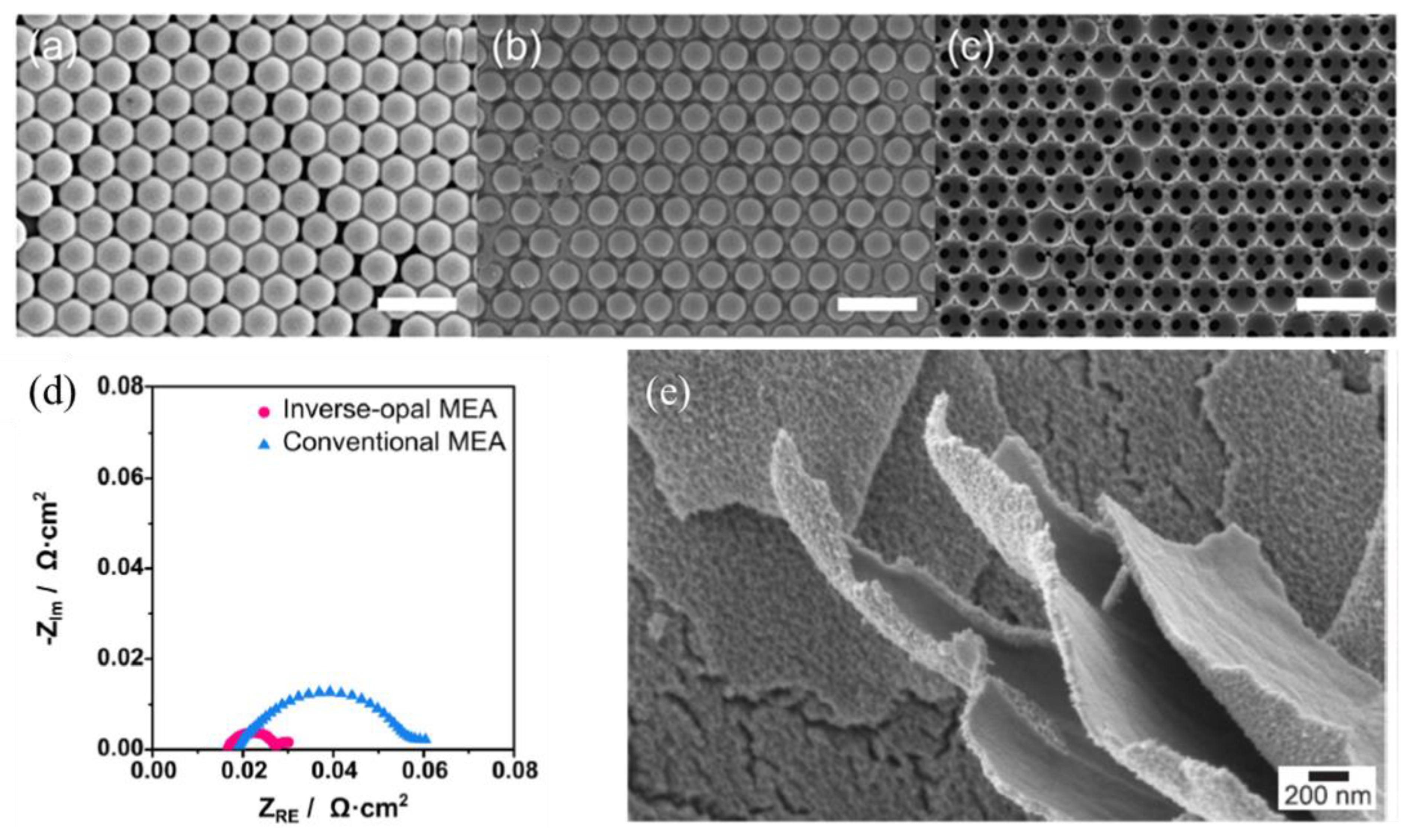
  51. Park, J.E.; Kim, S.; Kim, O.; Ahn, C.; Kim, M.; Kang, S.Y.; Jeon, T.I.; Shim, J.; Lee, D.W.; Lee, J.H. Ultra-low loading of IrO2 with an inverse-opal structure in a polymer-exchange membrane water electrolysis. Nano Energy 2019, 58, 158–166. [Google Scholar] [CrossRef]
  52. Oh, J.H.; Han, G.H.; Kim, H.; Jang, H.W.; Park, H.S.; Kim, S.Y.; Ahn, S.H. Activity and stability of Ir-based gas diffusion electrode for proton exchange membrane water electrolyzer. Chem Eng J. 2021, 420, 127696. [Google Scholar] [CrossRef]
  53. Lim, J.; Kang, G.; Lee, J.W.; Jeon, S.S.; Jeon, H.; Kang, P.W.; Lee, H. Amorphous Ir atomic clusters anchored on crystalline IrO2 nanoneedles for proton exchange membrane water oxidation. J. Power Sources 2022, 524, 231069. [Google Scholar] [CrossRef]
  54. Lee, S.W.; Baik, C.; Kim, D.; Pak, C. Control of Ir oxidation states to overcome the trade-off between activity and stability for the oxygen evolution reaction. J. Power Sources 2021, 493, 229689. [Google Scholar] [CrossRef]
  55. Lee, B.; Ahn, S.H.; Park, H.; Choi, I.; Yoo, S.J.; Kim, H.; Henkensmeier, D.; Kim, J.Y.; Park, S.; Nam, S.W. Development of electrodeposited IrO2 electrodes as anodes in polymer electrolyte membrane water electrolysis. Appl. Catal. B Environ. 2015, 179, 285–291. [Google Scholar] [CrossRef]
  56. Chatterjee, S.; Peng, X.; Intikhab, S.; Zeng, G.; Kariuki, N.N.; Myers, D.J.; Danilovic, N.; Snyder, J. Nanoporous Iridium Nanosheets for Polymer Electrolyte Membrane Electrolysis. Adv. Energy Mater. 2021, 11, 2101438. [Google Scholar] [CrossRef]
  57. Ghadge, S.D.; Velikokhatnyi, O.I.; Datta, M.K.; Shanthi, P.M.; Tan, S.; Damodaran, K.; Kumta, P.N. Experimental and theoretical validation of high efficiency and robust electrocatalytic response of one-dimensional (1D)(Mn, Ir) O2: 10F nanorods for the oxygen evolution reaction in PEM-based water electrolysis. ACS Catal. 2019, 9, 2134–2157. [Google Scholar] [CrossRef]
  58. Jiang, G.; Yu, H.; Hao, J.; Chi, J.; Fan, Z.; Yao, D.; Qin, B.; Shao, Z. An effective oxygen electrode based on Ir0.6Sn0.4O2 for PEM water electrolyzers. J. Energy Chem. 2019, 39, 23–28. [Google Scholar] [CrossRef]
  59. Lebedev, D.; Povia, M.; Waltar, K.; Abdala, P.M.; Castelli, I.E.; Fabbri, E.; Blanco, M.V.; Fedorov, A.; Copéret, C.; Marzari, N. Highly active and stable iridium pyrochlores for oxygen evolution reaction. Chem. Mater. 2017, 29, 5182–5191. [Google Scholar] [CrossRef]
  60. Lv, F.; Zhang, W.; Yang, W.; Feng, J.; Wang, K.; Zhou, J.; Zhou, P.; Guo, S. Ir-based alloy nanoflowers with optimized hydrogen binding energy as bifunctional electrocatalysts for overall water splitting. Small Methods 2020, 4, 1900129. [Google Scholar] [CrossRef]
  61. Ai, L.; Su, J.; Wang, M.; Jiang, J. Bamboo-structured nitrogen-doped carbon nanotube coencapsulating cobalt and molybdenum carbide nanoparticles: An efficient bifunctional electrocatalyst for overall water splitting. ACS Sustain. Chem. Eng. 2018, 6, 9912–9920. [Google Scholar] [CrossRef]
  62. Zheng, Y.; Zhang, F.; Wang, G.; Lai, D.; Zou, L.; Cheng, Q.; Li, J.; Zou, Z.; Yang, H. CO induced phase-segregation to construct robust and efficient IrRux@ Ir core-shell electrocatalyst towards acidic oxygen evolution. J. Power Sources 2022, 528, 231189. [Google Scholar] [CrossRef]
  63. Saveleva, V.A.; Wang, L.; Kasian, O.; Batuk, M.; Hadermann, J.; Gallet, J.; Bournel, F.; Alonso-Vante, N.; Ozouf, G.; Beauger, C. Insight into the mechanisms of high activity and stability of iridium supported on antimony-doped tin oxide aerogel for anodes of proton exchange membrane water electrolyzers. ACS Catal. 2020, 10, 2508–2516. [Google Scholar] [CrossRef]
  64. Kúš, P.; Ostroverkh, A.; Ševčíková, K.; Khalakhan, I.; Fiala, R.; Skála, T.; Tsud, N.; Matolin, V. Magnetron sputtered Ir thin film on TiC-based support sublayer as low-loading anode catalyst for proton exchange membrane water electrolysis. Int. J. Hydrogen Energy 2016, 41, 15124–15132. [Google Scholar] [CrossRef]
  65. Kim, H.; Kim, J.; Kim, J.; Han, G.H.; Guo, W.; Hong, S.; Park, H.S.; Jang, H.W.; Kim, S.Y.; Ahn, S.H. Dendritic gold-supported iridium/iridium oxide ultra-low loading electrodes for high-performance proton exchange membrane water electrolyzer. Appl. Catal. B Environ. 2021, 283, 119596. [Google Scholar] [CrossRef]
  66. Kim, E.; Shin, J.; Bak, J.; Lee, S.J.; hyun Kim, K.; Song, D.; Roh, J.; Lee, Y.; Kim, H.; Lee, K. Stabilizing role of Mo in TiO2-MoOx supported Ir catalyst toward oxygen evolution reaction. Appl. Catal. B Environ. 2021, 280, 119433. [Google Scholar] [CrossRef]
  67. Jiang, G.; Yu, H.; Li, Y.; Yao, D.; Chi, J.; Sun, S.; Shao, Z. Low-Loading and Highly Stable Membrane Electrode Based on an Ir@ WO x NR Ordered Array for PEM Water Electrolysis. ACS Appl. Mater. Interfaces 2021, 13, 15073–15082. [Google Scholar] [CrossRef]
  68. Islam, J.; Kim, S.; Thien, P.T.; Kim, M.; Cho, H.; Cho, W.; Kim, C.; Lee, C.; Lee, J.H. Enhancing the activity and durability of iridium electrocatalyst supported on boron carbide by tuning the chemical state of iridium for oxygen evolution reaction. J. Power Sources 2021, 512, 230506. [Google Scholar] [CrossRef]
  69. Hartig-Weiss, A.; Miller, M.; Beyer, H.; Schmitt, A.; Siebel, A.; Freiberg, A.T.; Gasteiger, H.A.; El-Sayed, H.A. Iridium oxide catalyst supported on antimony-doped tin oxide for high oxygen evolution reaction activity in acidic media. ACS Appl. Nano Mater. 2020, 3, 2185–2196. [Google Scholar] [CrossRef]
  70. Genova-Koleva, R.V.; Alcaide, F.; Álvarez, G.; Cabot, P.L.; Grande, H.; Martínez-Huerta, M.V.; Miguel, O. Supporting IrO2 and IrRuOx nanoparticles on TiO2 and Nb-doped TiO2 nanotubes as electrocatalysts for the oxygen evolution reaction. J. Energy Chem. 2019, 34, 227–239. [Google Scholar] [CrossRef]
  71. Steegstra, P.; Ahlberg, E. Influence of oxidation state on the pH dependence of hydrous iridium oxide films. Electrochim. Acta 2012, 76, 26–33. [Google Scholar] [CrossRef]
  72. Yamanaka, K. Anodically electrodeposited iridium oxide films (AEIROF) from alkaline solutions for electrochromic display devices. Jpn. J. Appl. Phys. 1989, 28, 632. [Google Scholar] [CrossRef]
  73. Terashima, C.; Rao, T.N.; Sarada, B.V.; Spataru, N.; Fujishima, A. Electrodeposition of hydrous iridium oxide on conductive diamond electrodes for catalytic sensor applications. J. Electroanal. Chem. 2003, 544, 65–74. [Google Scholar] [CrossRef]
  74. Ges, I.A.; Ivanov, B.L.; Werdich, A.A.; Baudenbacher, F.J. Differential pH measurements of metabolic cellular activity in nl culture volumes using microfabricated iridium oxide electrodes. Biosens. Bioelectron. 2007, 22, 1303–1310. [Google Scholar] [CrossRef] [PubMed]
  75. Feng, J.; Lv, F.; Zhang, W.; Li, P.; Wang, K.; Yang, C.; Wang, B.; Yang, Y.; Zhou, J.; Lin, F. Iridium-based multimetallic porous hollow nanocrystals for efficient overall-water-splitting catalysis. Adv. Mater. 2017, 29, 1703798. [Google Scholar] [CrossRef] [PubMed]
  76. Nong, H.N.; Oh, H.; Reier, T.; Willinger, E.; Willinger, M.; Petkov, V.; Teschner, D.; Strasser, P. Oxide-Supported IrNiOx Core–Shell Particles as Efficient, Cost-Effective, and Stable Catalysts for Electrochemical Water Splitting. Angew. Chem. Int. Ed. 2015, 54, 2975–2979. [Google Scholar] [CrossRef]
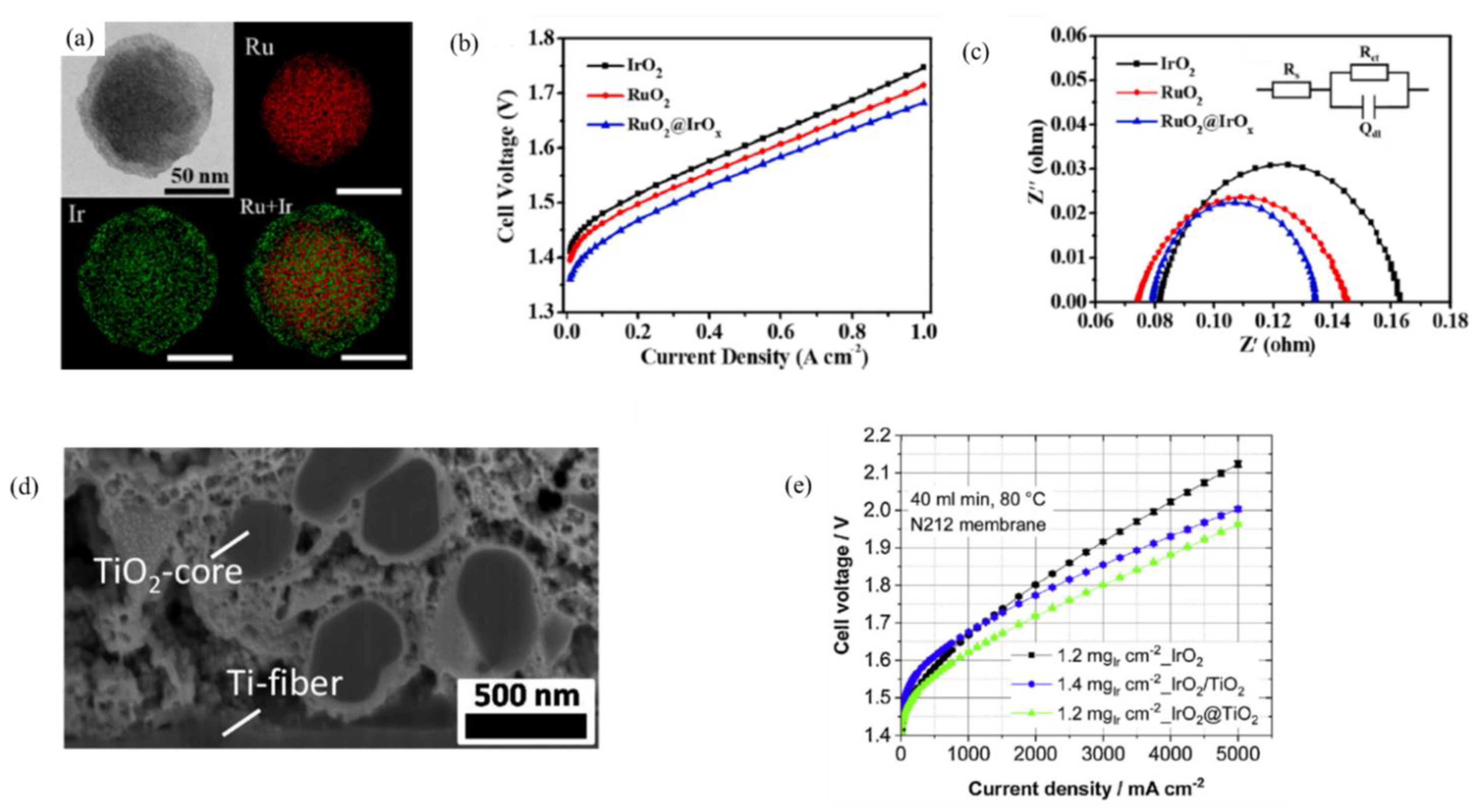
  77. Ma, Z.; Zhang, Y.; Liu, S.; Xu, W.; Wu, L.; Hsieh, Y.; Liu, P.; Zhu, Y.; Sasaki, K.; Renner, J.N. Reaction mechanism for oxygen evolution on RuO2, IrO2, and RuO2@ IrO2 core-shell nanocatalysts. J. Electroanal. Chem. 2018, 819, 296–305. [Google Scholar] [CrossRef]
  78. Escudero-Escribano, M.; Pedersen, A.F.; Paoli, E.A.; Frydendal, R.; Friebel, D.; Malacrida, P.; Rossmeisl, J.; Stephens, I.E.; Chorkendorff, I. Importance of Surface IrO x in Stabilizing RuO2 for Oxygen Evolution. J. Phys. Chem. B 2018, 122, 947–955. [Google Scholar] [CrossRef]
  79. Lv, H.; Wang, S.; Li, J.; Shao, C.; Zhou, W.; Shen, X.; Xue, M.; Zhang, C. Self-assembled RuO2@ IrOx core-shell nanocomposite as high efficient anode catalyst for PEM water electrolyzer. Appl. Surf. Sci 2020, 514, 145943. [Google Scholar] [CrossRef]
  80. Van Pham, C.; Bühler, M.; Knöppel, J.; Bierling, M.; Seeberger, D.; Escalera-López, D.; Mayrhofer, K.J.; Cherevko, S.; Thiele, S. IrO2 coated TiO2 core-shell microparticles advance performance of low loading proton exchange membrane water electrolyzers. Appl. Catal. B Environ. 2020, 269, 118762. [Google Scholar] [CrossRef]
  81. Faustini, M.; Giraud, M.; Jones, D.; Rozière, J.; Dupont, M.; Porter, T.R.; Nowak, S.; Bahri, M.; Ersen, O.; Sanchez, C. Hierarchically structured ultraporous iridium-based materials: A novel catalyst architecture for proton exchange membrane water electrolyzers. Adv. Energy Mater. 2019, 9, 1802136. [Google Scholar] [CrossRef]
  82. Siracusano, S.; Hodnik, N.; Jovanovic, P.; Ruiz-Zepeda, F.; Šala, M.; Baglio, V.; Aricò, A.S. New insights into the stability of a high performance nanostructured catalyst for sustainable water electrolysis. Nano Energy 2017, 40, 618–632. [Google Scholar] [CrossRef]
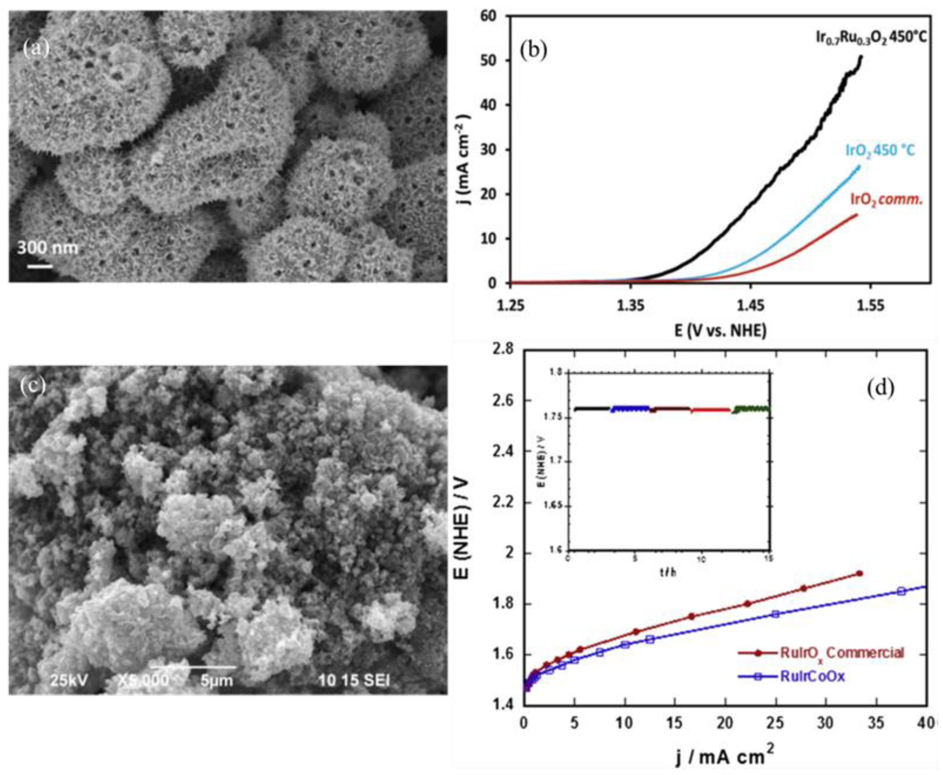
  83. Corona-Guinto, J.; Cardeño-García, L.; Martínez-Casillas, D.; Sandoval-Pineda, J.M.; Tamayo-Meza, P.; Silva-Casarin, R.; González-Huerta, R. Performance of a PEM electrolyzer using RuIrCoOx electrocatalysts for the oxygen evolution electrode. Int. J. Hydrogen Energy 2013, 38, 12667–12673. [Google Scholar] [CrossRef]
  84. Bernt, M.; Gasteiger, H.A. Influence of ionomer content in IrO2/TiO2 electrodes on PEM water electrolyzer performance. J. Electrochem. Soc. 2016, 163, F3179. [Google Scholar] [CrossRef]
  85. Marshall, A.T.; Sunde, S.; Tsypkin, M.; Tunold, R. Performance of a PEM water electrolysis cell using IrxRuyTazO2 electrocatalysts for the oxygen evolution electrode. Int. J. Hydrogen Energy 2007, 32, 2320–2324. [Google Scholar] [CrossRef]
  86. Li, G.; Li, K.; Yang, L.; Chang, J.; Ma, R.; Wu, Z.; Ge, J.; Liu, C.; Xing, W. Boosted performance of Ir species by employing TiN as the support toward oxygen evolution reaction. ACS Appl. Mater. Interfaces 2018, 10, 38117–38124. [Google Scholar] [CrossRef] [PubMed]
  87. Rozain, C.; Mayousse, E.; Guillet, N.; Millet, P. Influence of iridium oxide loadings on the performance of PEM water electrolysis cells: Part I–Pure IrO2-based anodes. Appl. Catal. B Environ. 2016, 182, 153–160. [Google Scholar] [CrossRef]
  88. Liu, G.; Xu, J.; Wang, Y.; Wang, X. An oxygen evolution catalyst on an antimony doped tin oxide nanowire structured support for proton exchange membrane liquid water electrolysis. J. Mater. Chem. A 2015, 3, 20791–20800. [Google Scholar] [CrossRef]
  89. Geiger, S.; Kasian, O.; Mingers, A.M.; Mayrhofer, K.J.; Cherevko, S. Stability limits of tin-based electrocatalyst supports. Sci. Rep. 2017, 7, 4595. [Google Scholar] [CrossRef]
  90. Polonský, J.; Mazúr, P.; Paidar, M.; Christensen, E.; Bouzek, K. Performance of a PEM water electrolyser using a TaC-supported iridium oxide electrocatalyst. Int. J. Hydrogen Energy 2014, 39, 3072–3078. [Google Scholar] [CrossRef]
  91. Oh, H.; Nong, H.N.; Reier, T.; Bergmann, A.; Gliech, M.; Ferreira de Arauújo, J.; Willinger, E.; Schloögl, R.; Teschner, D.; Strasser, P. Electrochemical catalyst–support effects and their stabilizing role for IrO x nanoparticle catalysts during the oxygen evolution reaction. J. Am. Chem. Soc. 2016, 138, 12552–12563. [Google Scholar] [CrossRef]
  92. Mazúr, P.; Polonský, J.; Paidar, M.; Bouzek, K. Non-conductive TiO2 as the anode catalyst support for PEM water electrolysis. Int. J. Hydrogen Energy 2012, 37, 12081–12088. [Google Scholar] [CrossRef]
  93. Karimi, F.; Peppley, B.A. Metal carbide and oxide supports for iridium-based oxygen evolution reaction electrocatalysts for polymer-electrolyte-membrane water electrolysis. Electrochim. Acta 2017, 246, 654–670. [Google Scholar] [CrossRef]
  94. Lv, H.; Zhang, G.; Hao, C.; Mi, C.; Zhou, W.; Yang, D.; Li, B.; Zhang, C. Activity of IrO2 supported on tantalum-doped TiO2 electrocatalyst for solid polymer electrolyte water electrolyzer. Rsc Adv. 2017, 7, 40427–40436. [Google Scholar] [CrossRef]
  95. Tariq, M.; Zaman, W.Q.; Wu, Y.; Nabi, A.; Abbas, Z.; Iqbal, W.; Sun, W.; Hao, Z.; Zhou, Z.H.; Cao, L. Facile synthesis of IrO2 nanoparticles decorated@ WO3 as mixed oxide composite for outperformed oxygen evolution reaction. Int. J. Hydrogen Energy 2019, 44, 31082–31093. [Google Scholar] [CrossRef]
  96. Siracusano, S.; Baglio, V.; Di Blasi, A.; Briguglio, N.; Stassi, A.; Ornelas, R.; Trifoni, E.; Antonucci, V.; Arico, A. Electrochemical characterization of single cell and short stack PEM electrolyzers based on a nanosized IrO2 anode electrocatalyst. Int. J. Hydrogen Energy 2010, 35, 5558–5568. [Google Scholar] [CrossRef]
  97. Siracusano, S.; Baglio, V.; Stassi, A.; Ornelas, R.; Antonucci, V.; Aricò, A. Investigation of IrO2 electrocatalysts prepared by a sulfite-couplex route for the O2 evolution reaction in solid polymer electrolyte water electrolyzers. Int. J. Hydrogen Energy 2011, 36, 7822–7831. [Google Scholar] [CrossRef]
  98. Seitz, L.C.; Dickens, C.F.; Nishio, K.; Hikita, Y.; Montoya, J.; Doyle, A.; Kirk, C.; Vojvodic, A.; Hwang, H.Y.; Norskov, J.K.; et al. A highly active and stable IrOx/SrIrO3 catalyst for the oxygen evolution reaction. Science 2016, 353, 1011–1014. [Google Scholar] [CrossRef]
  99. Puthiyapura, V.K.; Pasupathi, S.; Su, H.; Liu, X.; Pollet, B.; Scott, K. Investigation of supported IrO2 as electrocatalyst for the oxygen evolution reaction in proton exchange membrane water electrolyser. Int. J. Hydrogen Energy 2014, 39, 1905–1913. [Google Scholar] [CrossRef]
  100. Park, S.; Lee, J.; Popov, B.N. A review of gas diffusion layer in PEM fuel cells: Materials and designs. Int. J. Hydrogen Energy 2012, 37, 5850–5865. [Google Scholar] [CrossRef]
  101. Park, J.; Oh, H.; Lee, Y.I.; Min, K.; Lee, E.; Jyoung, J. Effect of the pore size variation in the substrate of the gas diffusion layer on water management and fuel cell performance. Appl. Energy 2016, 171, 200–212. [Google Scholar] [CrossRef]
  102. Mamaca, N.; Mayousse, E.; Arrii-Clacens, S.; Napporn, T.; Servat, K.; Guillet, N.; Kokoh, K. Electrochemical activity of ruthenium and iridium based catalysts for oxygen evolution reaction. Appl. Catal. B Environ. 2012, 111, 376–380. [Google Scholar] [CrossRef]
  103. Manzo-Robledo, A.; Boucher, A.; Pastor, E.; Alonso-Vante, N. Electro-oxidation of Carbon Monoxide and Methanol on Carbon-Supported Pt–Sn Nanoparticles: A DEMS Study. Fuel Cells 2002, 2, 109–116. [Google Scholar] [CrossRef]
  104. Ito, H.; Maeda, T.; Nakano, A.; Hwang, C.M.; Ishida, M.; Kato, A.; Yoshida, T. Experimental study on porous current collectors of PEM electrolyzers. Int. J. Hydrogen Energy 2012, 37, 7418–7428. [Google Scholar] [CrossRef]
  105. Lettenmeier, P.; Kolb, S.; Burggraf, F.; Gago, A.; Friedrich, K.A. Towards developing a backing layer for proton exchange membrane electrolyzers. J. Power Sources 2016, 311, 153–158. [Google Scholar] [CrossRef]
  106. Polonský, J.; Kodým, R.; Vágner, P.; Paidar, M.; Bensmann, B.; Bouzek, K. Anodic microporous layer for polymer electrolyte membrane water electrolysers. J. Appl. Electrochem. 2017, 47, 1137–1146. [Google Scholar] [CrossRef]
  107. Bystron, T.; Vesely, M.; Paidar, M.; Papakonstantinou, G.; Sundmacher, K.; Bensmann, B.; Hanke-Rauschenbach, R.; Bouzek, K. Enhancing PEM water electrolysis efficiency by reducing the extent of Ti gas diffusion layer passivation. J. Appl. Electrochem. 2018, 48, 713–723. [Google Scholar] [CrossRef]
  108. Wang, H.; Turner, J. Reviewing metallic PEMFC bipolar plates. Fuel Cells 2010, 10, 510–519. [Google Scholar] [CrossRef]
  109. Jung, H.; Huang, S.; Ganesan, P.; Popov, B.N. Performance of gold-coated titanium bipolar plates in unitized regenerative fuel cell operation. J. Power Sources 2009, 194, 972–975. [Google Scholar] [CrossRef]
  110. Choe, S.; Lee, B.; Cho, M.K.; Kim, H.; Henkensmeier, D.; Yoo, S.J.; Kim, J.Y.; Lee, S.Y.; Park, H.S.; Jang, J.H. Electrodeposited IrO2/Ti electrodes as durable and cost-effective anodes in high-temperature polymer-membrane-electrolyte water electrolyzers. Appl. Catal. B Environ. 2018, 226, 289–294. [Google Scholar] [CrossRef]
  111. Kang, Z.; Yang, G.; Mo, J.; Yu, S.; Cullen, D.A.; Retterer, S.T.; Toops, T.J.; Brady, M.P.; Bender, G.; Pivovar, B.S. Developing titanium micro/nano porous layers on planar thin/tunable LGDLs for high-efficiency hydrogen production. Int. J. Hydrogen Energy 2018, 43, 14618–14628. [Google Scholar] [CrossRef]
  112. Su, H.; Xu, Q.; Chong, J.; Li, H.; Sita, C.; Pasupathi, S. Eliminating micro-porous layer from gas diffusion electrode for use in high temperature polymer electrolyte membrane fuel cell. J. Power Sources 2017, 341, 302–308. [Google Scholar] [CrossRef]
  113. Hu, W.; Chen, S.; Xia, Q. IrO2/Nb–TiO2 electrocatalyst for oxygen evolution reaction in acidic medium. Int. J. Hydrogen Energy 2014, 39, 6967–6976. [Google Scholar] [CrossRef]
  114. Puthiyapura, V.K.; Mamlouk, M.; Pasupathi, S.; Pollet, B.G.; Scott, K. Physical and electrochemical evaluation of ATO supported IrO2 catalyst for proton exchange membrane water electrolyser. J. Power Sources 2014, 269, 451–460. [Google Scholar] [CrossRef]
  115. Grigoriev, S.; Millet, P.; Volobuev, S.; Fateev, V. Optimization of porous current collectors for PEM water electrolysers. Int. J. Hydrogen Energy 2009, 34, 4968–4973. [Google Scholar] [CrossRef]
  116. Schuler, T.; Ciccone, J.M.; Krentscher, B.; Marone, F.; Peter, C.; Schmidt, T.J.; Büchi, F.N. Hierarchically structured porous transport layers for polymer electrolyte water electrolysis. Adv. Energy Mater. 2020, 10, 1903216. [Google Scholar] [CrossRef]
  117. Sung, C.; Liu, C. A novel micro protective layer applied on a simplified PEM water electrolyser. Int. J. Hydrogen Energy 2013, 38, 10063–10067. [Google Scholar] [CrossRef]
  118. Liu, C.; Hu, L.; Sung, C. Micro-protective layer for lifetime extension of solid polymer electrolyte water electrolysis. J. Power Sources 2012, 207, 81–85. [Google Scholar] [CrossRef]
  119. Kang, Z.; Mo, J.; Yang, G.; Retterer, S.T.; Cullen, D.A.; Toops, T.J.; Green, J.B., Jr.; Mench, M.M.; Zhang, F. Investigation of thin/well-tunable liquid/gas diffusion layers exhibiting superior multifunctional performance in low-temperature electrolytic water splitting. Energy Environ. Sci. 2017, 10, 166–175. [Google Scholar] [CrossRef]
  120. Lettenmeier, P.; Kolb, S.; Sata, N.; Fallisch, A.; Zielke, L.; Thiele, S.; Gago, A.; Friedrich, K.A. Comprehensive investigation of novel pore-graded gas diffusion layers for high-performance and cost-effective proton exchange membrane electrolyzers. Energy Environ. Sci. 2017, 10, 2521–2533. [Google Scholar] [CrossRef]
  121. Kim, H.; Choe, S.; Park, H.; Jang, J.H.; Ahn, S.H.; Kim, S. An extremely low Pt loading cathode for a highly efficient proton exchange membrane water electrolyzer. Nanoscale 2017, 9, 19045–19049. [Google Scholar] [CrossRef]
  122. Egetenmeyer, A.; Radev, I.; Durneata, D.; Baumgärtner, M.; Peinecke, V.; Natter, H.; Hempelmann, R. Pulse electrodeposited cathode catalyst layers for PEM fuel cells. Int. J. Hydrogen Energy 2017, 42, 13649–13660. [Google Scholar] [CrossRef]
  123. Han, Y.J.; Zhang, X.; Leach, G.W. Shape control of electrodeposited copper films and nanostructures through additive effects. Langmuir 2014, 30, 3589–3598. [Google Scholar] [CrossRef] [PubMed]
  124. Liu, C.; Wippermann, K.; Rasinski, M.; Suo, Y.; Shviro, M.; Carmo, M.; Lehnert, W. Constructing a Multifunctional Interface between Membrane and Porous Transport Layer for Water Electrolyzers. ACS Appl. Mater. Interfaces 2021, 13, 16182–16196. [Google Scholar] [CrossRef]
  125. Park, Y.J.; Lee, J.; Park, Y.S.; Yang, J.; Jang, M.J.; Jeong, J.; Choe, S.; Lee, J.W.; Kwon, J.; Choi, S.M. Electrodeposition of high-surface-area IrO2 films on Ti felt as an efficient catalyst for the oxygen evolution reaction. Front. Chem. 2020, 8, 593272. [Google Scholar] [CrossRef] [PubMed]
  126. Wang, M.; Wang, Z.; Gong, X.; Guo, Z. The intensification technologies to water electrolysis for hydrogen production—A review. Renew. Sustain. Energy Rev. 2014, 29, 573–588. [Google Scholar] [CrossRef]
  127. Chalker, P.; Bull, S.; Rickerby, D. A review of the methods for the evaluation of coating-substrate adhesion. Mater. Sci. Eng. A 1991, 140, 583–592. [Google Scholar] [CrossRef]
  128. Lee, B.; Park, H.; Choi, I.; Cho, M.K.; Kim, H.; Yoo, S.J.; Henkensmeier, D.; Kim, J.Y.; Nam, S.W.; Park, S. Polarization characteristics of a low catalyst loading PEM water electrolyzer operating at elevated temperature. J. Power Sources 2016, 309, 127–134. [Google Scholar] [CrossRef]
  129. Antonucci, V.; Di Blasi, A.; Baglio, V.; Ornelas, R.; Matteucci, F.; Ledesma-Garcia, J.; Arriaga, L.; Aricò, A. High temperature operation of a composite membrane-based solid polymer electrolyte water electrolyser. Electrochim. Acta 2008, 53, 7350–7356. [Google Scholar] [CrossRef]
  130. Baglio, V.; Ornelas, R.; Matteucci, F.; Martina, F.; Ciccarella, G.; Zama, I.; Arriaga, L.; Antonucci, V.; Aricò, A. Solid Polymer Electrolyte Water Electrolyser Based on Nafion-TiO2 Composite Membrane for High Temperature Operation. Fuel Cells 2009, 9, 247–252. [Google Scholar] [CrossRef]
  131. Xu, W.; Scott, K.; Basu, S. Performance of a high temperature polymer electrolyte membrane water electrolyser. J. Power Sources 2011, 196, 8918–8924. [Google Scholar] [CrossRef]
  132. Kim, J.Y.; Choi, J.; Kim, H.Y.; Hwang, E.; Kim, H.; Ahn, S.H.; Kim, S. Activity and stability of the oxygen evolution reaction on electrodeposited Ru and its thermal oxides. Appl. Surf. Sci 2015, 359, 227–235. [Google Scholar] [CrossRef]
  133. Lee, B.; Park, H.; Cho, M.K.; Jung, J.W.; Kim, H.; Henkensmeier, D.; Yoo, S.J.; Kim, J.Y.; Park, S.; Lee, K. Development of porous Pt/IrO2/carbon paper electrocatalysts with enhanced mass transport as oxygen electrodes in unitized regenerative fuel cells. Electrochem. Commun. 2016, 64, 14–17. [Google Scholar] [CrossRef]
  134. Lim, A.; Kim, J.; Lee, H.J.; Kim, H.; Yoo, S.J.; Jang, J.H.; Park, H.Y.; Sung, Y.; Park, H.S. Low-loading IrO2 supported on Pt for catalysis of PEM water electrolysis and regenerative fuel cells. Appl. Catal. B Environ. 2020, 272, 118955. [Google Scholar] [CrossRef]
  135. Liu, C.; Shviro, M.; Gago, A.S.; Zaccarine, S.F.; Bender, G.; Gazdzicki, P.; Morawietz, T.; Biswas, I.; Rasinski, M.; Everwand, A. Exploring the Interface of Skin-Layered Titanium Fibers for Electrochemical Water Splitting. Adv. Energy Mater. 2021, 11, 2002926. [Google Scholar] [CrossRef]
  136. Li, X.; Sabir, I. Review of bipolar plates in PEM fuel cells: Flow-field designs. Int. J. Hydrogen Energy 2005, 30, 359–371. [Google Scholar] [CrossRef]
  137. Park, J.; Li, X. Effect of flow and temperature distribution on the performance of a PEM fuel cell stack. J. Power Sources 2006, 162, 444–459. [Google Scholar] [CrossRef]
  138. Lædre, S.; Kongstein, O.E.; Oedegaard, A.; Karoliussen, H.; Seland, F. Materials for Proton Exchange Membrane water electrolyzer bipolar plates. Int. J. Hydrogen Energy 2017, 42, 2713–2723. [Google Scholar] [CrossRef]
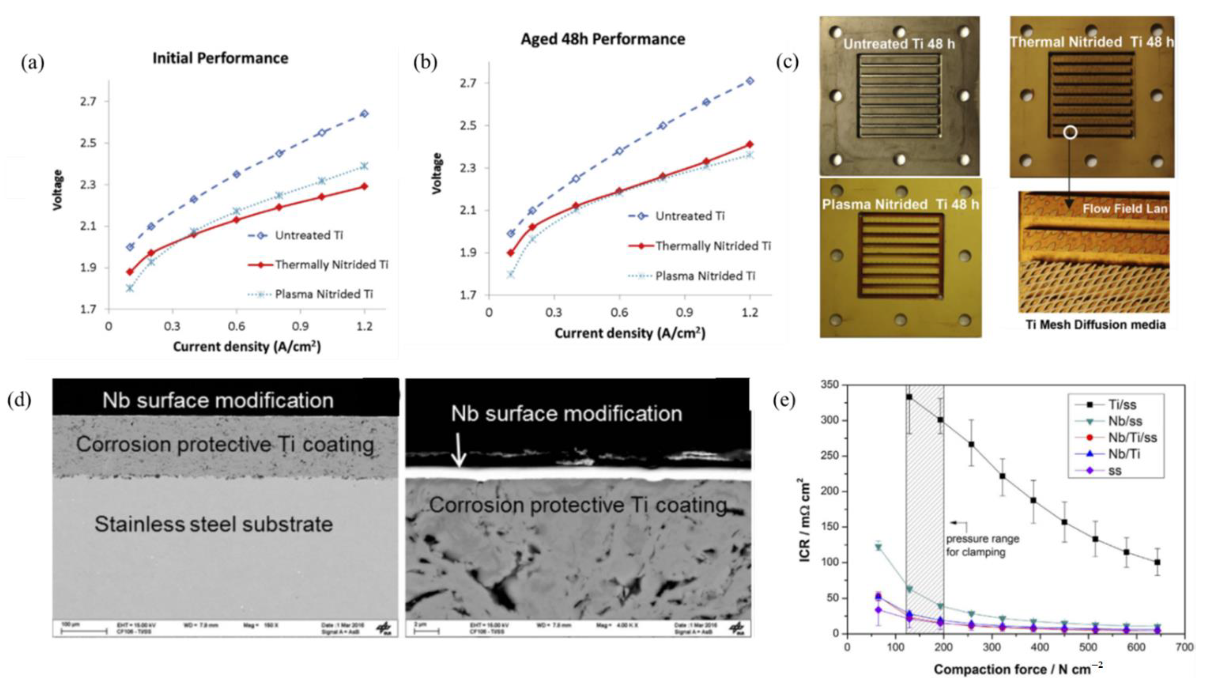
  139. Lettenmeier, P.; Wang, R.; Abouatallah, R.; Saruhan, B.; Freitag, O.; Gazdzicki, P.; Morawietz, T.; Hiesgen, R.; Gago, A.; Friedrich, K. Low-cost and durable bipolar plates for proton exchange membrane electrolyzers. Sci. Rep. 2017, 7, 44035. [Google Scholar] [CrossRef] [PubMed]
  140. Bessarabov, D.; Wang, H.; Li, H.; Zhao, N. PEM Electrolysis for Hydrogen Production: Principles and Applications; CRC Press: Boca Raton, FL, USA, 2016. [Google Scholar]
  141. Toops, T.J.; Brady, M.P.; Zhang, F.; Meyer, H.M., III; Ayers, K.; Roemer, A.; Dalton, L. Evaluation of nitrided titanium separator plates for proton exchange membrane electrolyzer cells. J. Power Sources 2014, 272, 954–960. [Google Scholar] [CrossRef]
  142. Jung, H.; Huang, S.; Popov, B.N. High-durability titanium bipolar plate modified by electrochemical deposition of platinum for unitized regenerative fuel cell (URFC). J. Power Sources 2010, 195, 1950–1956. [Google Scholar] [CrossRef]
  143. Wang, J.; Wang, W.; Wang, C.; Mao, Z. Corrosion behavior of three bipolar plate materials in simulated SPE water electrolysis environment. Int. J. Hydrogen Energy 2012, 37, 12069–12073. [Google Scholar] [CrossRef]
  144. Zhang, M.; Hu, L.; Lin, G.; Shao, Z. Honeycomb-like nanocomposite Ti-Ag-N films prepared by pulsed bias arc ion plating on titanium as bipolar plates for unitized regenerative fuel cells. J. Power Sources 2012, 198, 196–202. [Google Scholar] [CrossRef]
  145. Lin, M.; Wan, C.; Wu, W. Comparison of corrosion behaviors between SS304 and Ti substrate coated with (Ti, Zr) N thin films as Metal bipolar plate for unitized regenerative fuel cell. Thin Solid Films 2013, 544, 162–169. [Google Scholar] [CrossRef]
  146. Nikiforov, A.; Petrushina, I.; Christensen, E.; Tomás-García, A.; Bjerrum, N. Corrosion behaviour of construction materials for high temperature steam electrolysers. Int. J. Hydrogen Energy 2011, 36, 111–119. [Google Scholar] [CrossRef]
  147. Lettenmeier, P.; Wang, R.; Abouatallah, R.; Burggraf, F.; Gago, A.; Friedrich, K. Coated stainless steel bipolar plates for proton exchange membrane electrolyzers. J. Electrochem. Soc. 2016, 163, F3119. [Google Scholar] [CrossRef]
  148. Wu, J.; Yuan, X.Z.; Martin, J.J.; Wang, H.; Zhang, J.; Shen, J.; Wu, S.; Merida, W. A review of PEM fuel cell durability: Degradation mechanisms and mitigation strategies. J. Power Sources 2008, 184, 104–119. [Google Scholar] [CrossRef]
  149. Sun, S.; Shao, Z.; Yu, H.; Li, G.; Yi, B. Investigations on degradation of the long-term proton exchange membrane water electrolysis stack. J. Power Sources 2014, 267, 515–520. [Google Scholar] [CrossRef]
  150. Wang, X.; Zhang, L.; Li, G.; Zhang, G.; Shao, Z.; Yi, B. The influence of Ferric ion contamination on the solid polymer electrolyte water electrolysis performance. Electrochim. Acta 2015, 158, 253–257. [Google Scholar] [CrossRef]
  151. Gago, A.S.; Ansar, A.S.; Gazdzicki, P.; Wagner, N.; Arnold, J.; Friedrich, K.A. Low cost bipolar plates for large scale PEM electrolyzers. ECS Trans. 2014, 64, 1039. [Google Scholar] [CrossRef]
  152. Gago, A.; Ansar, A.; Wagner, N.; Arnold, J.; Friedrich, K.A. Titanium coatings deposited by thermal spraying for bipolar plates of PEM electrolysers. In Proceedings of the 4th European PEFC and H2 Forum, Lucerne, Switzerland, 2–5 July 2013. [Google Scholar]
  153. Kim, K.M.; Kim, J.H.; Lee, Y.Y.; Kim, K.Y. Electrodeposition of ruthenium oxide on ferritic stainless steel bipolar plate for polymer electrolyte membrane fuel cells. Int. J. Hydrogen Energy 2012, 37, 1653–1660. [Google Scholar] [CrossRef]
  154. Kumar, A.; Ricketts, M.; Hirano, S. Ex situ evaluation of nanometer range gold coating on stainless steel substrate for automotive polymer electrolyte membrane fuel cell bipolar plate. J. Power Sources 2010, 195, 1401–1407. [Google Scholar] [CrossRef]
  155. Rojas, N.; Sánchez-Molina, M.; Sevilla, G.; Amores, E.; Almandoz, E.; Esparza, J.; Vivas, M.R.C.; Colominas, C. Coated stainless steels evaluation for bipolar plates in PEM water electrolysis conditions. Int. J. Hydrogen Energy 2021, 46, 25929–25943. [Google Scholar] [CrossRef]
  156. Lee, S.; Woo, S.; Kakati, N.; Lee, Y.; Yoon, Y. Corrosion and electrical properties of carbon/ceramic multilayer coated on stainless steel bipolar plates. Surf. Coat. Technol. 2016, 303, 162–169. [Google Scholar] [CrossRef]
  157. Choi, Y.; Lee, W.; Na, Y. Effect of Gravity and Various Operating Conditions on Proton Exchange Membrane Water Electrolysis Cell Performance. Membranes 2021, 11, 822. [Google Scholar] [CrossRef] [PubMed]
  158. Kai, J.; Saito, R.; Terabaru, K.; Li, H.; Nakajima, H.; Ito, K. Effect of temperature on the performance of polymer electrolyte membrane water electrolysis: Numerical analysis of electrolysis voltage considering gas/liquid two-phase flow. J. Electrochem. Soc. 2019, 166, F246. [Google Scholar] [CrossRef]
  159. Chandesris, M.; Médeau, V.; Guillet, N.; Chelghoum, S.; Thoby, D.; Fouda-Onana, F. Membrane degradation in PEM water electrolyzer: Numerical modeling and experimental evidence of the influence of temperature and current density. Int. J. Hydrogen Energy 2015, 40, 1353–1366. [Google Scholar] [CrossRef]
  160. Inaba, M.; Kinumoto, T.; Kiriake, M.; Umebayashi, R.; Tasaka, A.; Ogumi, Z. Gas crossover and membrane degradation in polymer electrolyte fuel cells. Electrochim. Acta 2006, 51, 5746–5753. [Google Scholar] [CrossRef]
  161. Yoshitake, M.; Tamura, M.; Yoshida, N.; Ishisaki, T. Studies of perfluorinated ion exchange membranes for polymer electrolyte fuel cells. Denki Kagaku Oyobi Kogyo Butsuri Kagaku 1996, 64, 727–736. [Google Scholar] [CrossRef]
  162. Kaya, M.F.; Demir, N.; Rees, N.V.; El-Kharouf, A. Improving PEM water electrolyser’s performance by magnetic field application. Appl. Energy 2020, 264, 114721. [Google Scholar] [CrossRef]
  163. Olesen, A.C.; Rømer, C.; Kær, S.K. A numerical study of the gas-liquid, two-phase flow maldistribution in the anode of a high pressure PEM water electrolysis cell. Int. J. Hydrogen Energy 2016, 41, 52–68. [Google Scholar] [CrossRef] [Green Version]
  164. Hoeh, M.A.; Arlt, T.; Manke, I.; Banhart, J.; Fritz, D.L.; Maier, W.; Lehnert, W. In operando synchrotron X-ray radiography studies of polymer electrolyte membrane water electrolyzers. Electrochem. Commun. 2015, 55, 55–59. [Google Scholar] [CrossRef]
  165. Lopata, J.; Kang, Z.; Young, J.; Bender, G.; Weidner, J.; Shimpalee, S. Effects of the transport/catalyst layer interface and catalyst loading on mass and charge transport phenomena in polymer electrolyte membrane water electrolysis devices. J. Electrochem. Soc. 2020, 167, 064507. [Google Scholar] [CrossRef]
  166. Zhang, X.; Zhang, W.; Yang, W.; Liu, W.; Min, F.; Mao, S.S.; Xie, J. Catalyst-coated proton exchange membrane for hydrogen production with high pressure water electrolysis. Appl. Phys. Lett 2021, 119, 123903. [Google Scholar] [CrossRef]
  167. Stiber, S.; Balzer, H.; Wierhake, A.; Wirkert, F.J.; Roth, J.; Rost, U.; Brodmann, M.; Lee, J.K.; Bazylak, A.; Waiblinger, W. Porous Transport Layers for Proton Exchange Membrane Electrolysis Under Extreme Conditions of Current Density, Temperature, and Pressure. Adv. Energy Mater. 2021, 11, 2100630. [Google Scholar] [CrossRef]
  168. Bernt, M.; Schröter, J.; Möckl, M.; Gasteiger, H. Analysis of gas permeation phenomena in a PEM water electrolyzer operated at high pressure and high current density. J. Electrochem. Soc. 2020, 167, 124502. [Google Scholar] [CrossRef]
Figure 1. Schematic of the PEM electrolyzer showing its main components [34].
Electrochem 03 00040 g001
Figure 2. FE-SEM images of each step in the decal-transfer method: (a) self-assembled polystyrene beads as a template, (b) infiltration of IrO2 by using pulse electrodeposition, (c) inverse-opal electrode (the scale bar is 1 μm), and (d) Nyquist plot at 1.6 V for Inverse-opal and the conventional MEA. Reproduced with permission [51]. Copyright 2019, Elsevier Inc. (e) SEM of npIrx-NS. Reproduced with permission [56]. Copyright 2021, John Wiley and Sons.
Electrochem 03 00040 g002
Figure 3. (a) TEM image of core shell RuO2@IrOx nanoparticles and their corresponding EDX mapping, which shows the presence of Ru and Ir. (b) Polarization curves of the membrane electrode assemblies (MEAs) using RuO2, IrO2, and RuO2@IrOx as the OER catalyst. (c) Nyquist plots of the MEAs fabricated by using different catalysts, data were taken in the single cell at 0.1 A·cm−2 and 80 °C; the inset shows the equivalent circuit model. Reproduced with permission [79]. Copyright 2020, Elsevier Inc. (d) FIB/SEM cross-sections of the IrO2@TiO2 catalyst layers, the catalyst was deposited on titanium porous transport layers (PTL) containing 5 wt. % Nafion. (e) Polarization curves of the PEM water electrolysis cells using IrO2@TiO2 catalysts and commercially available unsupported IrO2 (Alfa Aesar) and IrO2/TiO2 (Umicore). Reproduced with permission [80]. Copyright 2020, Elsevier Inc.
Electrochem 03 00040 g003
Figure 4. (a) SEM of Ir0.7Ru0.3Ox catalyst calcined at 450 °C. (b) Cyclic voltammetry (forward scan) was recorded at 6 mV·s−1 of the Ir0.7Ru0.3O2 and IrOx samples obtained after calcination in air at 450 °C and commercial IrO2 with total catalyst loading of 0.0176 mg. Reproduced with permission [81]. Copyright 2018, John Wiley and Sons. (c) SEM of RuIrCoOx OER catalyst. (d) Polarization curves on a single cell (electrodes area of 4 cm2) with RuIrCoOx and RuIrOx catalysts, the inset shows electrolyzer voltage vs. time measured during the initial 15 h of operation at 25 °C. Reproduced with permission [83]. Copyright 2013, Elsevier Inc.
Electrochem 03 00040 g004
Figure 5. (a) TEM images of the unsupported 40IrO2/Ti0.9Ta0.1O2 catalyst (b) Polarization curves of a single electrolysis cell with different IrO2 loadings of Ti0.7Ta0.3O2 [94].
Electrochem 03 00040 g005
Figure 6. (a) Cross-section SEM image of titanium microporous layer (MPL) with a thickness of 20 μm over 25 μm gas diffusion layer. 5 μm microparticles of titanium particles were deposited as an MPL. (b) Polarization, and (c) Nyquist plot of the PEM electrolysis cell using a Liquid gas diffusion layer (LGDL) with 5 μm Ti particles as an MPL with a thickness of (A1 = 15 μm), (A2 = 20 μm) and (A3 = 40 μm), where A is the LGDL with the thickness of 25 μm and pore diameter of 800 μm. Reproduce with permission [111]. Copyright 2018, Elsevier Inc.
Electrochem 03 00040 g006
Figure 7. (a) SEM image of Ti GDL by the E-beam (EBM) method, alloy powder of Ti-6Al-4 V was used for the fabrication process, (b) Nyquist plot comparison of conventional woven Ti Mesh and GDL by the EBM method. Reproduced with permission [7]. Copyright 2016, Elsevier Inc., and (c) SEM image of pore graded porous transport layer, when used as a GDL, the top part will be in contact with the electrode and bottom part will be in contact with the bipolar plate [120].
Electrochem 03 00040 g007
Figure 8. (a) SEM images of the IrO2 catalyst deposited on carbon paper, (IrO2/CP) electrodes fabricated by electrodeposition at 0.7 V for 10 min, (b) Polarization curves of the PEM water electrolysis using single cells with IrO2/CP anodes (deposition voltage = 0.7 V; deposition time was from 1–30 min). Reproduced with permission [55]. Copyright 2015, Elsevier Inc. (c) SEM of IrO2 coated on Ti felt; the titanium felt was etched for 30 min before the deposition of IrO2. (d) Tafel plots with iR correction of different electrodes fabricated by changing the etching time from 0 to 40 min prior to the deposition of IrO2 [125].
Electrochem 03 00040 g008
Figure 9. (a) Polarization curves at 25°C with nitrided and unmodified bipolar plates. (b) Polarization curves after 48 h of operation. (c) Images of bipolar plates after 48 h, magnified image of thermal nitride plate flow field with Ti metal mesh. Reproduced with permission [141]. Copyright 2014, Elsevier Inc. (d) Cross-sectional SEM with low and high magnification of bipolar plates. (e) Graph showing interfacial contact resistance vs. the compaction force on the bipolar plates [139].
Electrochem 03 00040 g009
Figure 10. (a) Polarization curves of PEMWE at the different operating temperatures [157]. (b) Recommended region of operation pressure at each current density [158]. (c) Time evolution of the membrane thickness in percentage at 1 A·cm−2 at 333 K and 353 K. Plain lines: coupled model taking into account the thinning of the membrane; dotted lines: linear model without coupling with the membrane thinning. Reproduced with permission [159]. Copyright (2015), Elsevier Inc. (d) Effects of gas pressure on H2 crossover current density at different cell temperatures. Reproduced with permission [160]. Copyright (2006), Elsevier Inc.
Electrochem 03 00040 g010
Figure 11. Effect of flow rate on the performance of the: (a) non-magnetized, and (b) 0.5 T magnetized PEMWE cell. Reproduced with permission [162]. Copyright (2020), Elsevier Inc. (c) Polarization curves of PEMWE at the different flow rates [157]. (d) Current density vs. the anode water feed rate for the 4 cm2 PEMWE cell under potentiostatic control at 55 °C. PTL pore opening sizes are given in the legend [165].
Electrochem 03 00040 g011
Figure 12. (a) Effect of gas production pressures on the stack performance. Reproduced with permission [166]. Copyright (2021), AIP Publishing. The volume fraction of H2 (XH2) in the O2–containing anode gas vs. current density for PEMWE operation at different H2 partial pressures and ambient pressure in the anode compartment at 80 °C based on the H2 permeation rates for (b) Nafion117 and (c) Nafion 212 [168]. (d) Polarization curve with PSL/mesh-PTL at a pressure of 1 and 90 bar at 52 and 90 °C up to 6 A·cm−2. The dashed lines represent the simulated polarization curve of PSL/mesh-PTL at 1 and 90 bar as well as 90 °C up to 6 A·cm−2. Reproduced with permission [167]. Copyright 2021, John Wiley and Sons.
Electrochem 03 00040 g012
Publisher’s Note: MDPI stays neutral with regard to jurisdictional claims in published maps and institutional affiliations.

