
A Novel Dual-Band Implantable Antenna for Pancreas Telemetry Sensor Applications


Electrical and Computer Engineering Department, University of Patras, 26504 Patras, Greece
*
Authors to whom correspondence should be addressed.
Telecom 2022, 3(1), 1-16; https://0-doi-org.brum.beds.ac.uk/10.3390/telecom3010001
Submission received: 21 November 2021
/
Revised: 6 December 2021
/
Accepted: 10 December 2021
/
Published: 1 January 2022
(This article belongs to the Special Issue Modern Circuits and Systems Technologies on Communications 2021)
Abstract
:In this study, a novel implantable dual-band planar inverted F-antenna (PIFA) is proposed and designed for wireless biotelemetry. The developed antenna is intended to operate on the surface of the pancreas within the Medical Device Radiocommunications Service (MedRadio 401–406 MHz) and the industrial scientific and medical band (ISM, 2.4–2.5 GHz). The design analysis was carried out in two steps, initially inside a canonical model representing the pancreas, based on a finite element method (FEM) numerical solver. The proposed antenna was further simulated inside the human body taking into account the corresponding dimensions of the tissues and the electrical properties at the frequencies of interest using a finite-difference time-domain (FDTD) numerical solver. Resonance, radiation performance, electrical field attenuation, total radiated power, and specific absorption rate (SAR), which determines the safety of the patient and the maximum permissible input power and other electromagnetic parameters, are presented and evaluated.
1. Introduction
In recent years, significant research has been made in wireless body area networks and their applications in the field of telemedicine. Specifically, implantable medical devices are widely used for the transmission of vital data. Their development creates the prospects for a better life quality of patients, especially those who suffer from chronic diseases [1]. For example, continuous non-invasive glucose monitoring can help patients suffering from diabetes, a very common, life-threatening disease. To carry out such an application, the antenna must be carefully designed, given that it provides a communication link between the internal and the external sensor and that it is responsible for the radiation performance and the transmission of the electromagnetic waves. Such an application could be used in a sensor that will be informed about the glucose levels of the pancreas, then send the results to a sensor on the surface or outside the body, which will communicate with a doctor via the internet and regulate the levels of insulin to be taken by the patient.
An implantable device has many requirements and a single operating band may not meet some of them since it needs to transmit data and be autonomous at the same time. Consequently, it is highly demanded to have multiband operation for other functions such as wireless power transfer and/or wake-up/sleep modes. Research on the dual band function of implantable antennas has been reported for example in [2,3,4].
This study is an extended version of our work reported in [5], where we presented the design of a novel implantable dual-band antenna and its performance simulated inside a cuboid pancreas model with dielectric properties of the pancreas. In this work, the proposed antenna’s function is further analyzed through simulations inside the pancreas of a male and a female human phantom, taking into account the impact of the human body on the signal propagation and the safety limits of the absorbed energy by surrounding tissues. The antenna resonates at MedRadio and ISM bands, aiming to serve different functions of the implantable device. In order be small-sized, a shorting pin was inserted, given that it plays a significant role in the miniaturization of the antenna [6,7,8,9,10]. Research also has been conducted regarding the use of U-shaped slots to achieve the multiband operation of the patch antenna [11,12,13,14].
Furthermore, we focused on a printed double-resonance slotted patch antenna, loaded with u-shaped slots and a pin that were used to introduce and tune the double resonance. The frequencies sought were the Medical Device Radiocommunications Service (MedRadio) 401–406 MHz and Industrial, Scientific, and Medical 2.4–2.5 GHz frequency bands. The former could serve for information transmission to an external receiver, while the latter could serve for wireless charging. The use of a full metallic ground plane thus had a second role. It could serve as backing for a circuit or other metallic structures without affecting the antenna performance [4]. In addition, we sought a slot antenna because of its superior far-field radiation properties and its robustness against tissue variability, which is usual in such designs.
The antenna design process followed a two-step approach: the first step was to achieve resonance inside an equivalent simplified model with the dielectric properties of the pancreas. To design the antenna, each element was inserted depending on the impact of the antenna behavior, surface current density, and radiation performance. Some useful conclusions are presented in every stage of the design until resonance was achieved. In this step, we used HFSS Software (High Frequency Structure Simulator) [15].
The second step was to implant the antenna in a more accurate human phantom with the help of the software Sim4Life of ZMT, Zurich MedTech [16]. The behavior of the antenna was analyzed when it was placed on the surface of the pancreas of two anatomical models (male and female) with all the electric properties and geometrical characteristics of biological tissues for the analysis of signal behavior as it propagated through the human organs. Radiation performance, electric field distributions, SAR values, and maximum allowable power values as well as electric field fluctuations when the electromagnetic wave was away from the antenna were calculated and evaluated in each anatomical model, and a comparative study was performed between the two models.
2. Methods and Results
2.1. Antenna Design
The main objective of the proposed antenna design process was to be as small as possible, which made the design quite complex as it depended on many parameters (geometrical shape and size of the antenna components). To achieve a better size reduction, we chose a very thin substrate of high-dielectric material [8] and installed a small pin which transforms this antenna into a PIFA (planar inverted F-antenna). The choice of the pin position was based on the observation that the maximum size reduction would be achieved by placing the pin away from the zero point of the electric field as well as at a suitable point so that it did not affect the tuning of the antenna.
Furthermore, another requirement was to transmit in two frequency bands MedRadio and ISM for the transmission of vital data and its energy management. To achieve the function at both frequencies, two U-shaped slots were placed on the conductive surface which redefined the path of the surface currents. The basic geometry of the U-slotted antenna was first introduced in 1995 by Huyn and Lee [17].
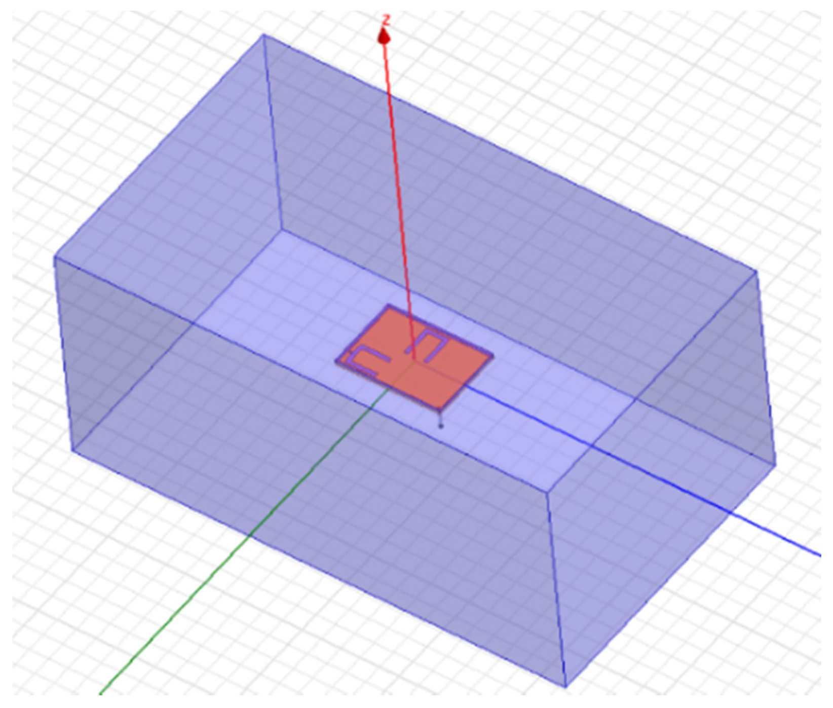
The antenna was designed directly into the pancreas rectangle box displayed in Figure 1, and the shorting pin position and U-slots placement and dimensions were manually optimized to achieve optimum performance at the frequencies of interest, using HFSS Software (high frequency structure simulator) [15].
Antenna Characteristics
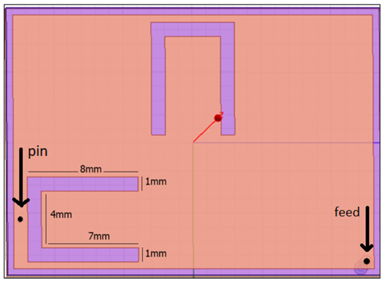
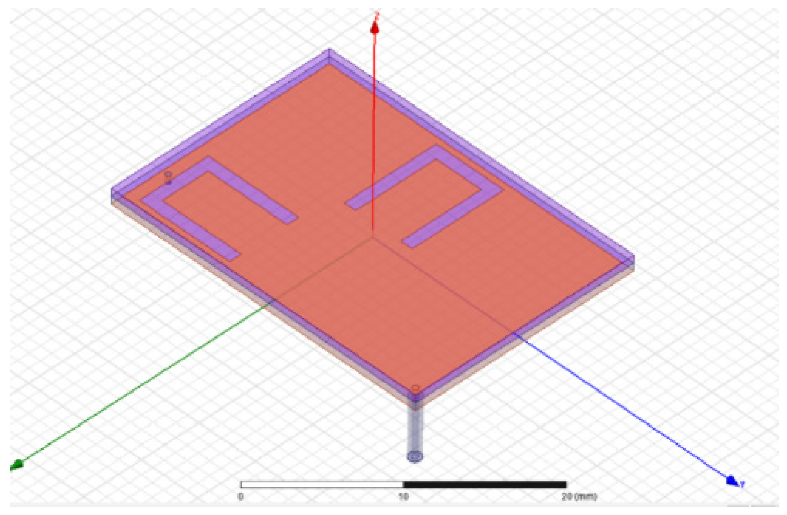
The patch surface and ground plane had dimensions of 18 mm × 26 mm and 19 mm × 27 mm, illustrated in Figure 2 and Figure 3. The substrate was made of high-dielectric material (Rogers RO 6010 εr = 10.2, tan δ = 0.023) and a thickness of 0.635 mm. An identical superstrate layer covered the patch surface to insulate the metallic radiating patch from the surrounding human tissues. In the edge of the antenna, we inserted a shorting pin with radius of 0.2 mm, shown in Figure 2. Two U-shaped slots were added in the patch surface, with dimensions shown in Figure 1. A 50 Ω coaxial cable of 5 mm length was used as feed, which consisted of an external conductor (radius = 0.48 mm) made of dielectric material Teflon (tm) (εr = 2.2) and an internal one (radius 0.24 mm).
The antenna was designed in the center of a simplified equivalent model, with the electrical properties of the pancreas and the shape of a rectangle box of dimensions 74 mm × 127 mm × 59 mm. The electrical properties of the pancreas that represent the pancreas tissue at the frequencies of interest are shown in Table 1 from IT’IS database [18].
2.2. Radiation Performance Analysis
2.2.1. Resonance
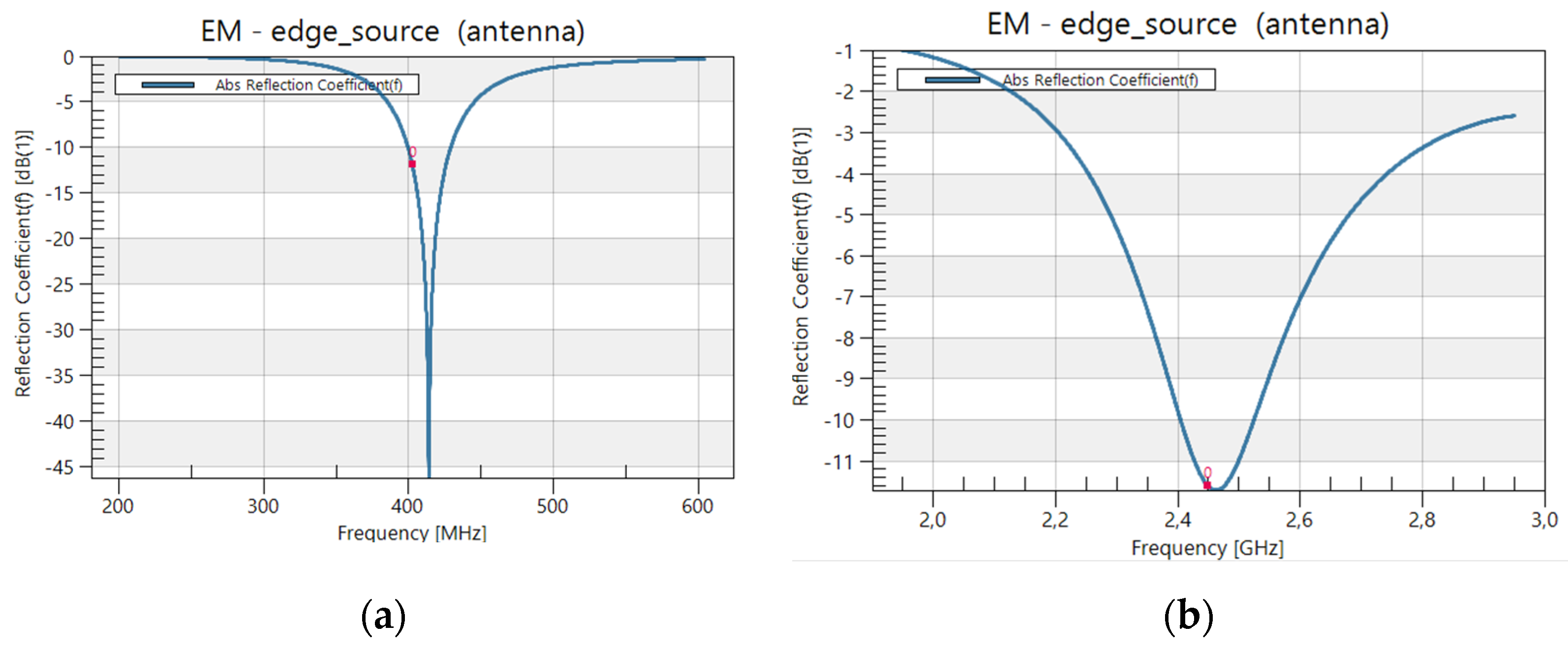
In order to understand the antenna behavior, resonance performance dependence on structure modifications was analyzed. For both frequencies, we requested that S11 resonance fell below −10 dB.
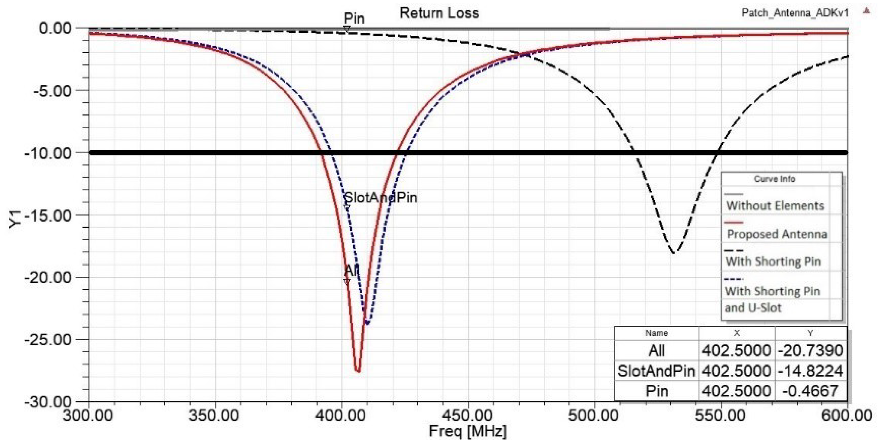
In the MedRadio band, before any structure modification, the antenna showed no resonance, as displayed in Figure 4. When the antenna turned into PIFA, we observed a resonance at 430 MHz. With every U-slot addition, the resonance improved, and the S11 reached −20.7 dB. The 10 dB bandwidth was 30.29 MHz.
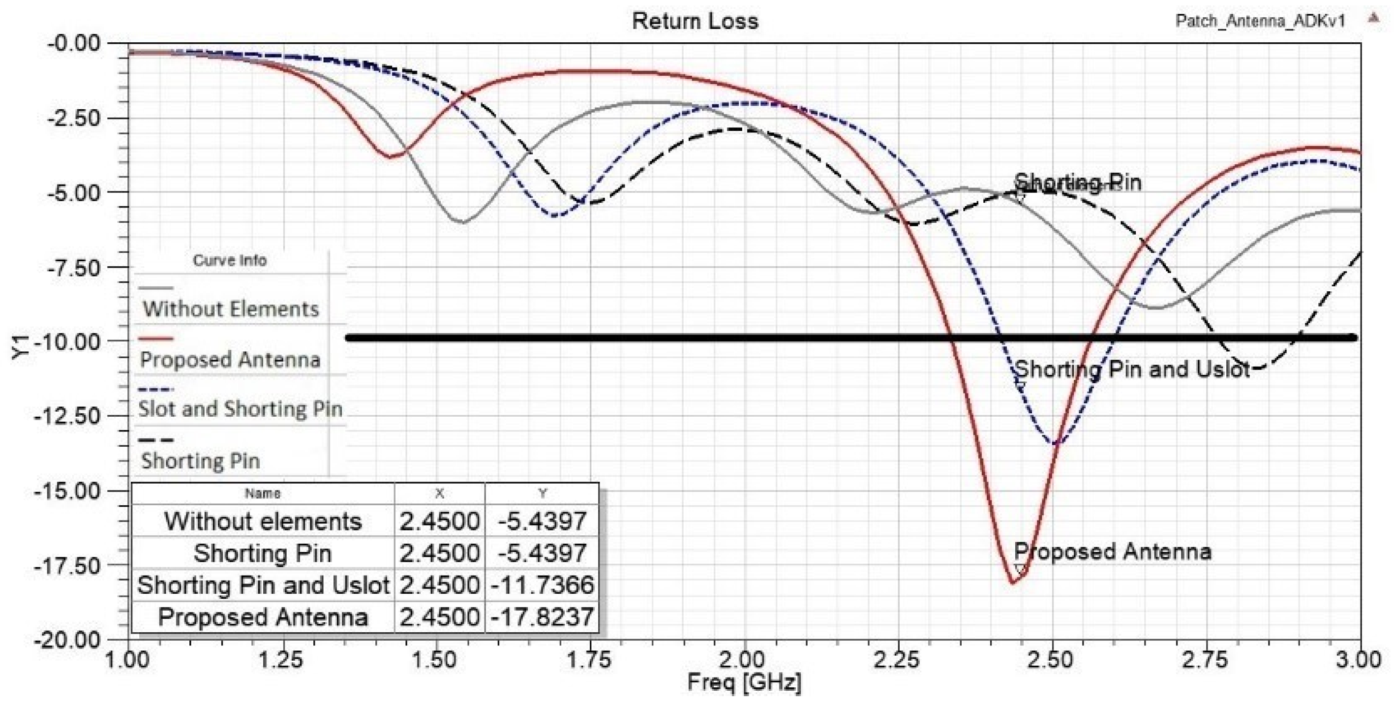
The impact on the reflection coefficient in the ISM band operation is shown in Figure 5. Without adding any elements, we observed a possible resonance although it did not cover the −10dB requirement. After the structure modifications, the existing resonance optimized and S11 was −17.8 dB at the operating frequency of 2.45 GHz. The bandwidth was 225.2 MHz.
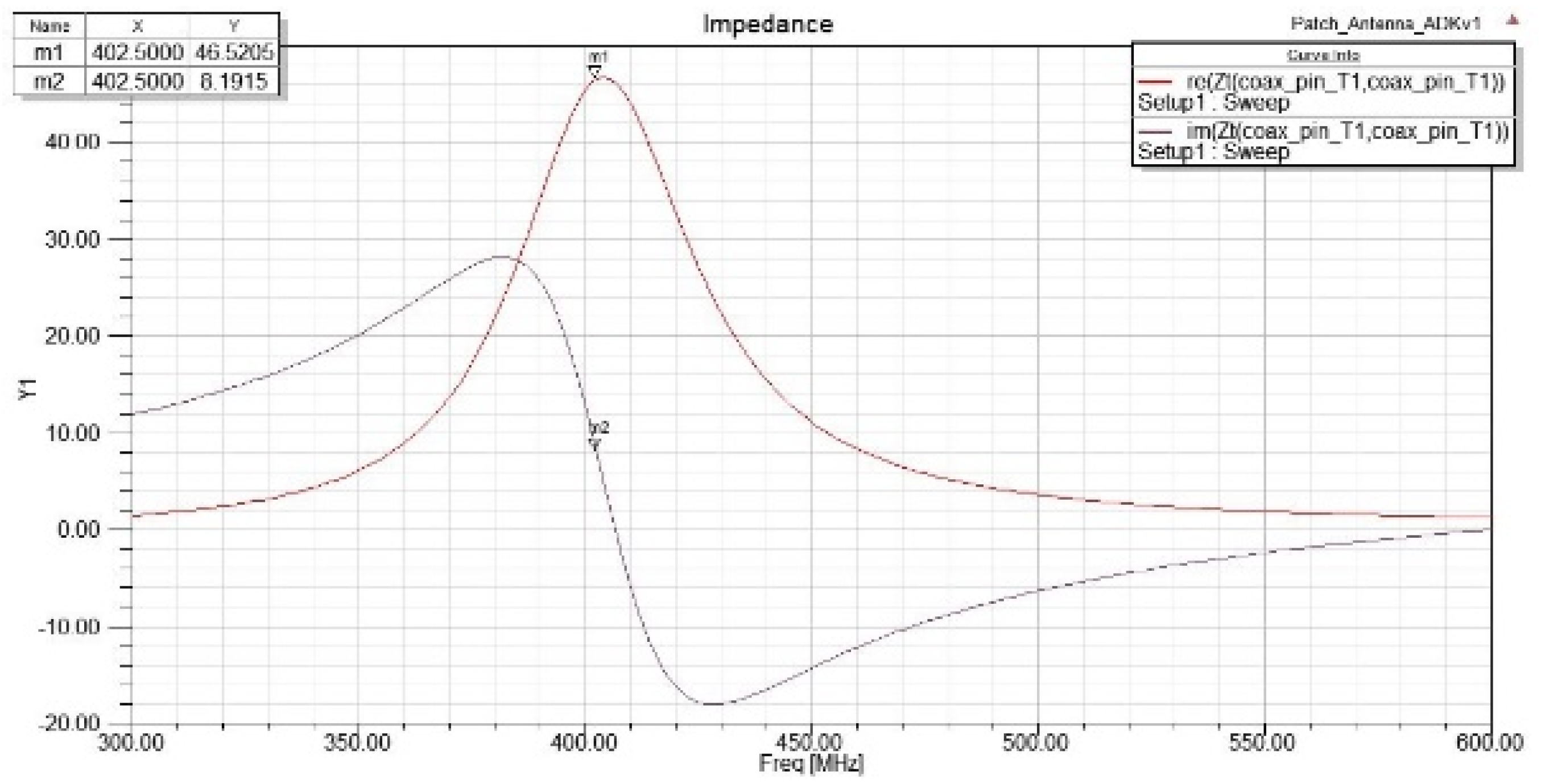
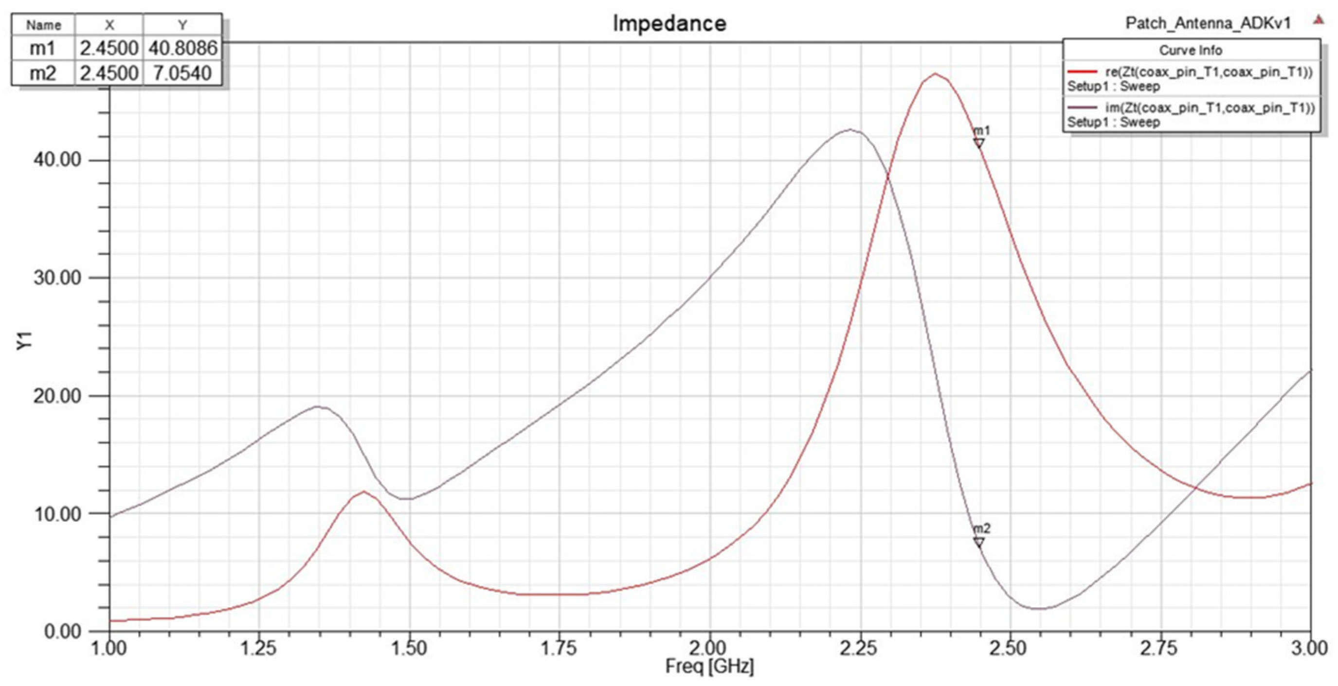
Overall, the proposed antenna performance on the desired operation frequencies satisfied the −10 dB limit, indicated by the black line in Figure 4 and Figure 5. In addition, the 10 dB bandwidth covered the MedRadio and ISM bands. In addition, at 402.5MHz the real part of the impedance of the proposed antenna, extracted from our simulations, is 46.52 Ω and the imaginary 8.19, and at 2.45GHz the real part is 40.8 Ω and the imaginary part is 7Ω as displayed in Figure 6 and Figure 7.
2.2.2. Surface Current Density
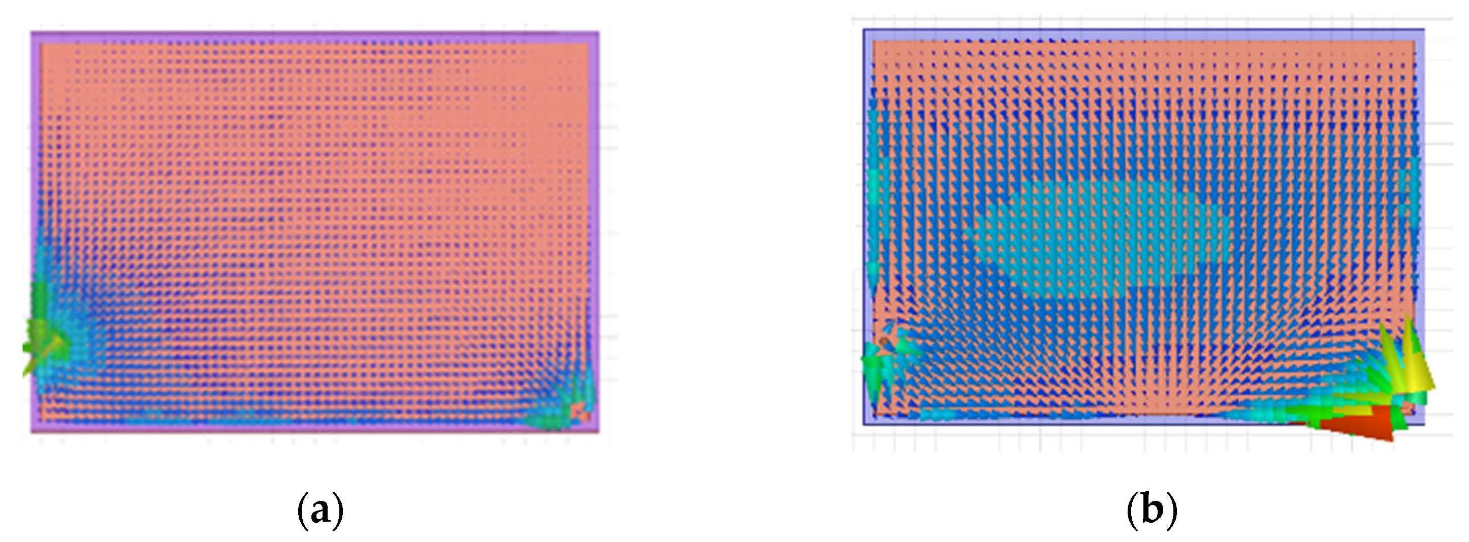
The influence of the structure modifications on the antenna surface current density is presented. The impact of the antenna structure modifications on the current distribution is shown in Figure 8, Figure 9, Figure 10 and Figure 11.
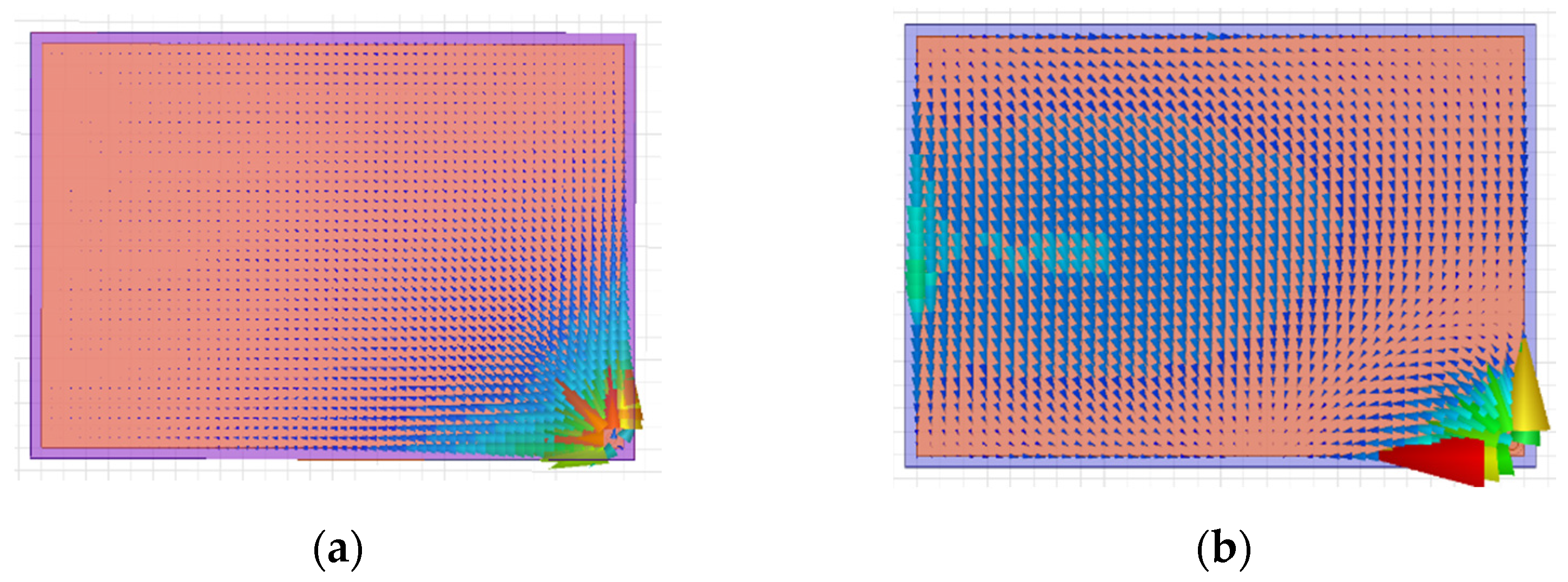
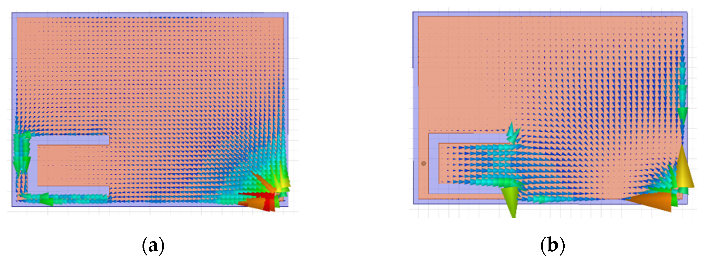
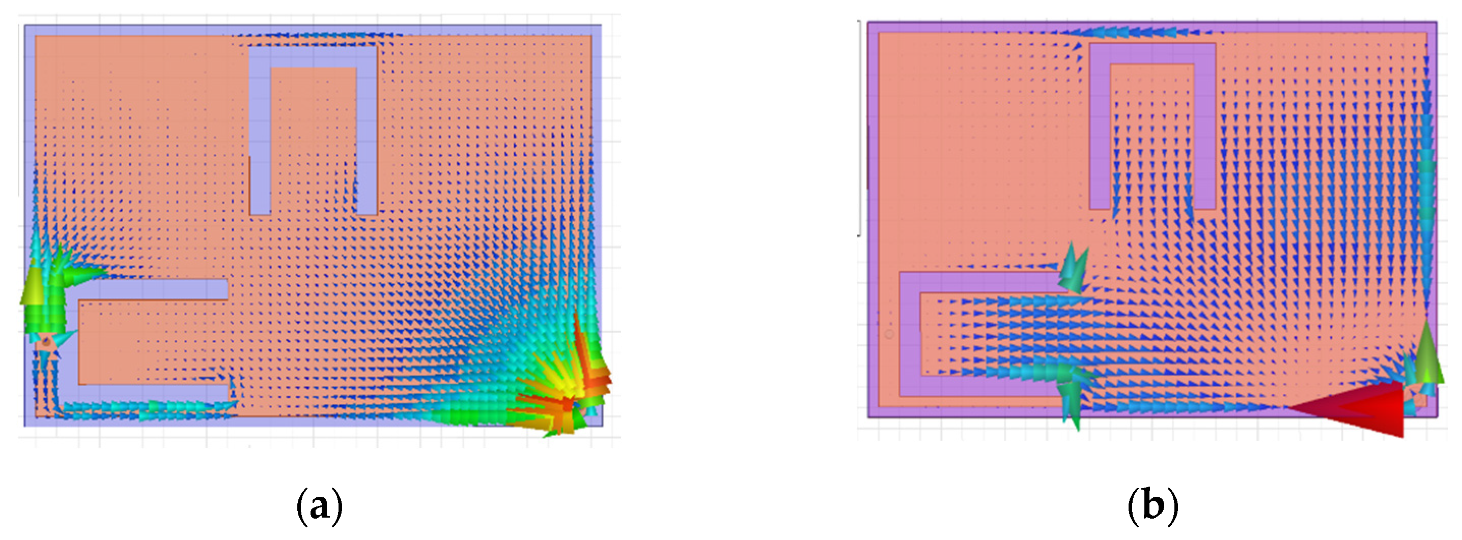
At 402.5 MHz, the surface current was mostly concentrated near the feed. Adding the shorting pin, the surface current was directed towards the pin, as shown in Figure 9a. This explains the resonance that occurred with the pin insertion, noted before. Adding the U-shaped slots distributed the surface current around the perimeter of the antenna surface, as shown in Figure 10a and Figure 11a, and shifted the resonance to the left. As a result of these changes, the antenna tuned in the MedRadio band. In the ISM band, the shorting pin did not much affect the surface current’s course.
It was observed that the current distribution was concentrated in the middle of the surface, as shown in Figure 9b. Changes occurred in the surface current distribution due to the U-slots, as displayed in Figure 10b and Figure 11b, which made the antenna resonance shift to the left and tune at the ISM band. In the ISM band, the current distribution was more affected by the U-slots than by the pin, compared with the MedRadio band.
2.2.3. Realized Gain
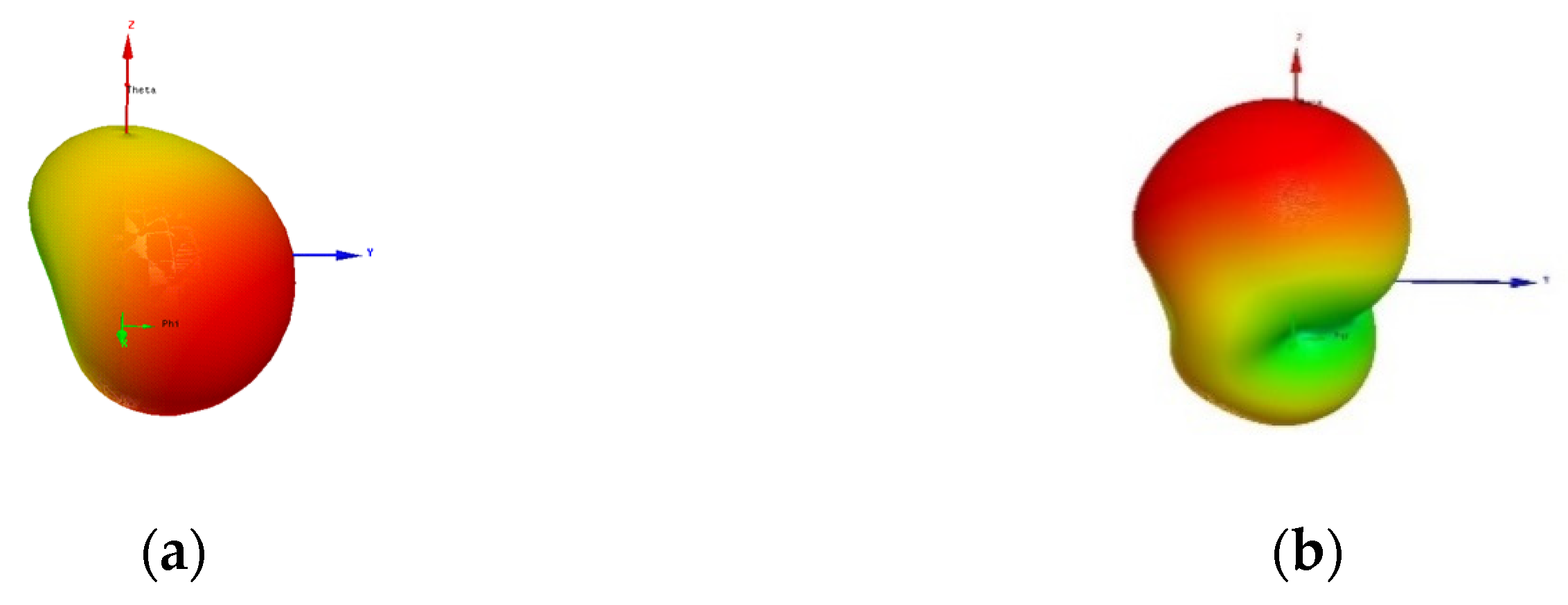
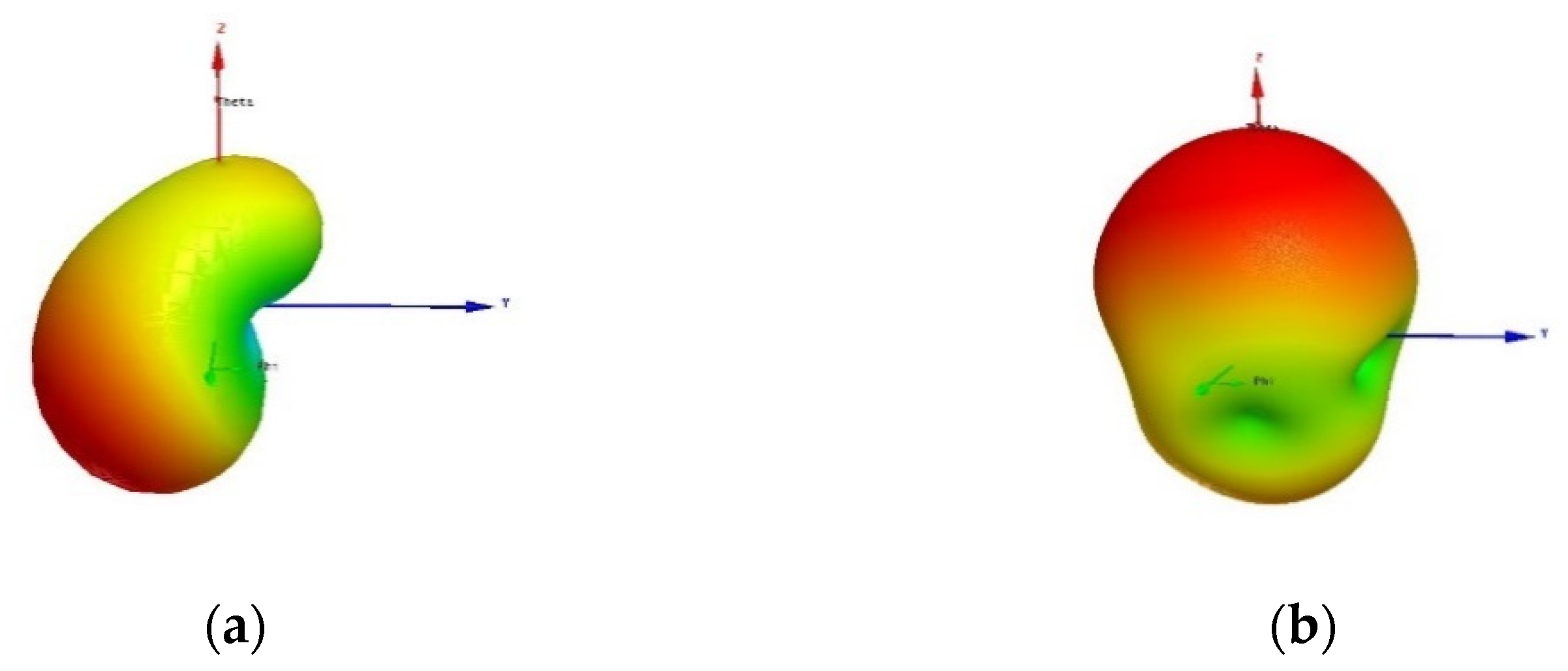
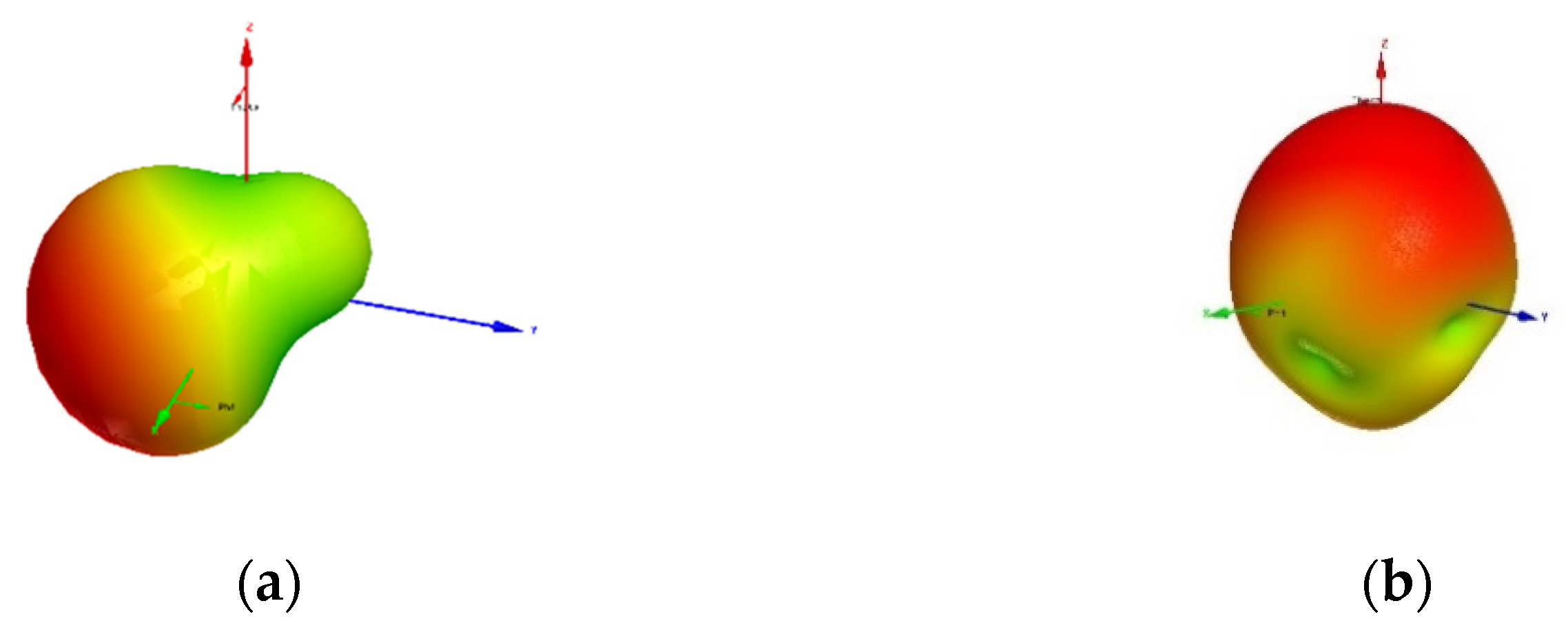
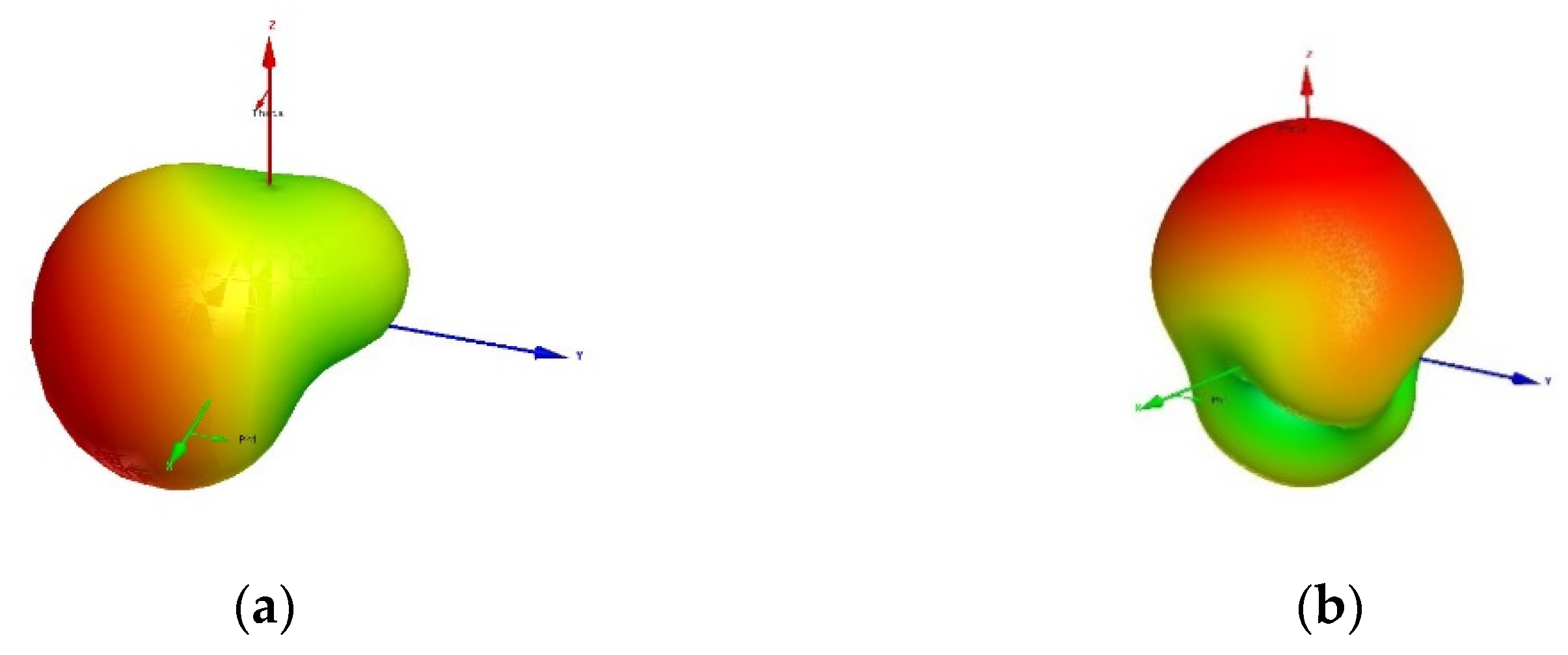
It was observed that in every stage of the antenna design the 3D radiation pattern changed depending on the frequency of interest and the results are displayed in Figure 12, Figure 13, Figure 14 and Figure 15. Peak radiation concentration is shown in red color.
Moreover, realized gain values changed with the structure modifications and reached their peak values with −31 dB at 402.5 MHz and −22 dB at 2.45 GHz. The antenna showed directional behavior in both frequencies. In the MedRadio band, the radiation pattern was directed to the x − (−y), as shown in Figure 15a plane, and in the ISM band, it was directed to the z axis. Table 2 shows the results of maximum Realized Antenna Gain extracted from simulations.
2.2.4. Electric Current Distribution
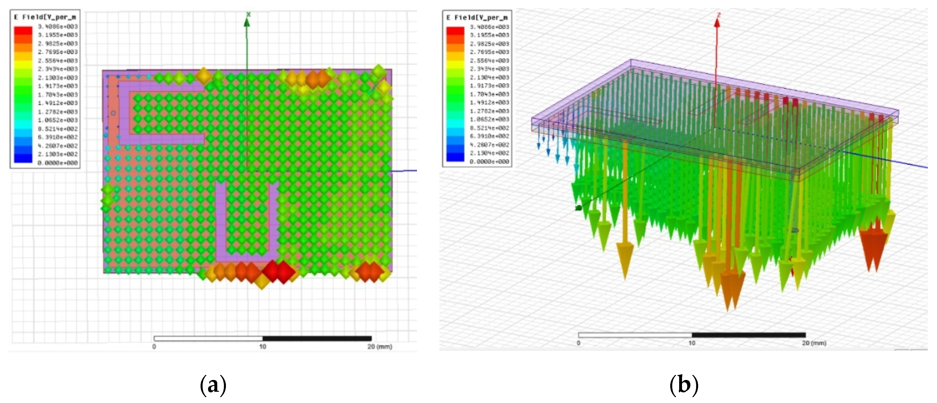
In general, complex phenomena were observed in the electric field due to the small size of the antenna so it was difficult to predict its distribution. However, we can draw some useful conclusions. For 1 W input power at the feed, the maximum electric field at 402.5 MHz was 3408 V/m, and at 2.45 GHz, it was 3770 V/m. The peak values of the electric field for both frequencies are shown in the Table 3.
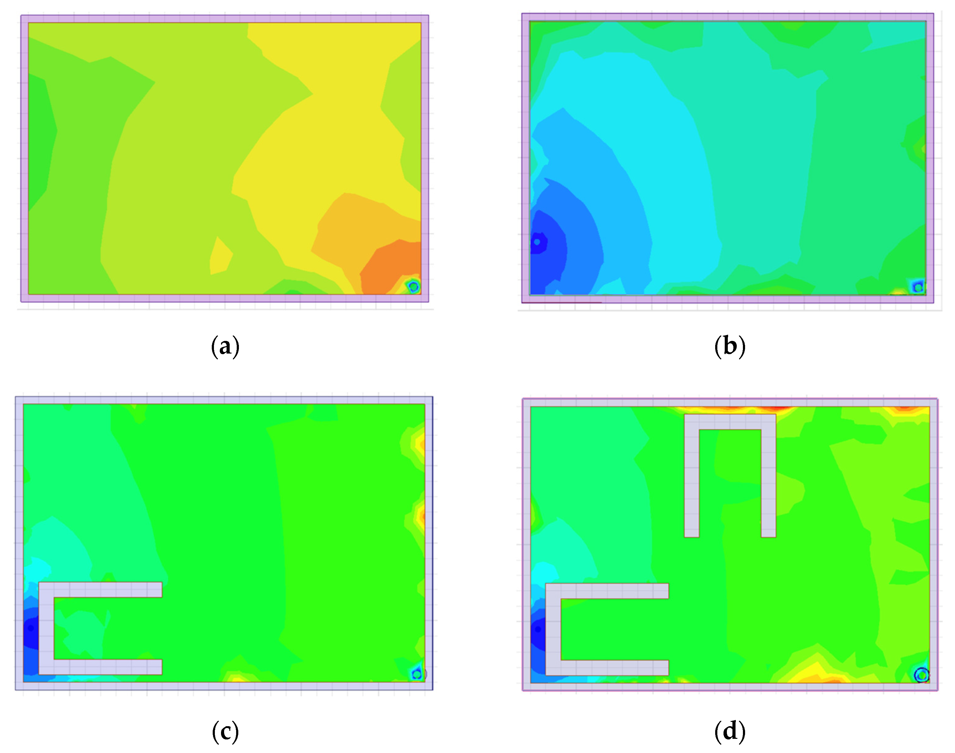
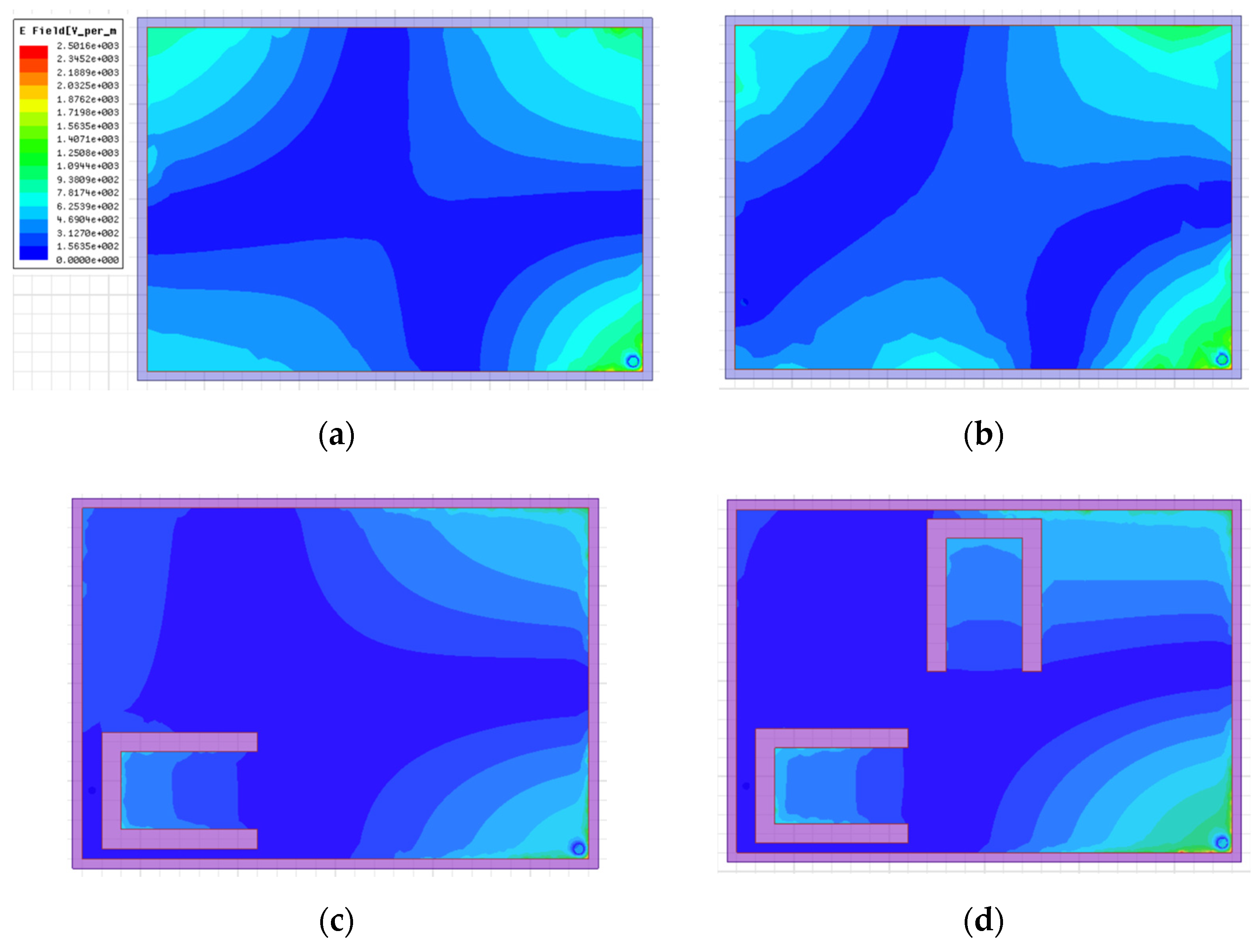
Electric field distribution at 402.5 MHz when every component is inserted is shown in Figure 16. Initially, the electric field of the plane microstrip antenna was very weak, with a maximum value 47 V/m and equally distributed in the conductive surface. As we inserted the shorting pin, the electric field concentrated on the edges, and the maximum value changed to 1007 V/m. This also shows why the resonance occurs when we insert the pin. When the U slots are added, the electric field distribution did not present significant changes, and the maximum values increased to 3408 V/m for the proposed antenna, which explained why the tunning improved with these structure modifications. Obviously, we fully exploited the antenna surface to achieve maximum radiation.
Figure 17 shows the electric field distribution of the proposed antenna at 402.5 MHz displayed in two- dimensional and three-dimensional space as displayed from our simulations.
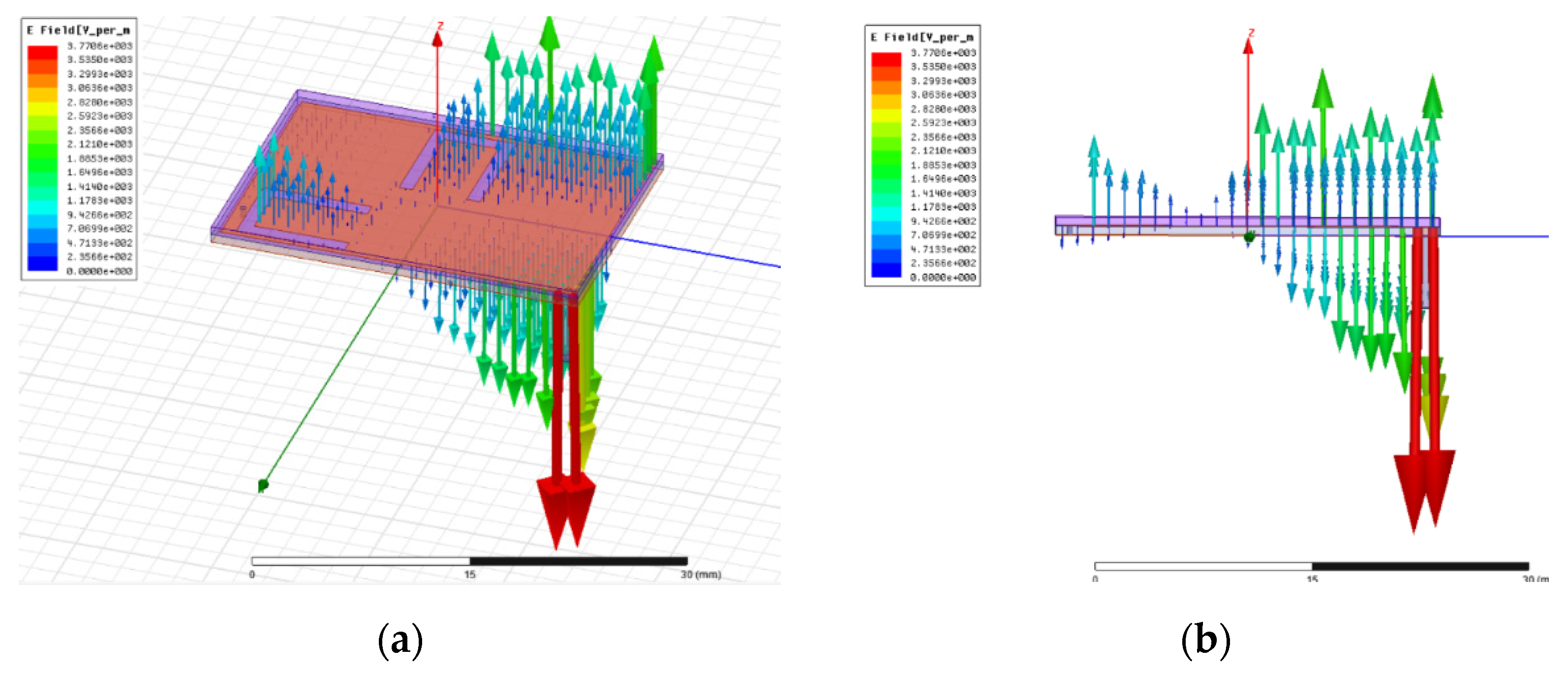
The electric field distribution at the ISM band, displayed in Figure 18, was similar in all steps of the design procedure, as the resonant mode already existed from the plain microstrip patch antenna before inserting any elements. It was observed that the maximum electric field distribution was found on the edges and the maximum value was at 2501 V/m before any modification while it increased to 3770 V/m after adding all the elements. In this case, antenna radiation mechanisms changed. Less than half of the antenna volume is now used, and resonance is along the x axis.
Figure 19 shows the electric field density of the proposed antenna at 2.45 GHz displayed in two- dimensional and three-dimensional space.
2.3. Antenna Simulation in Anatomical Models
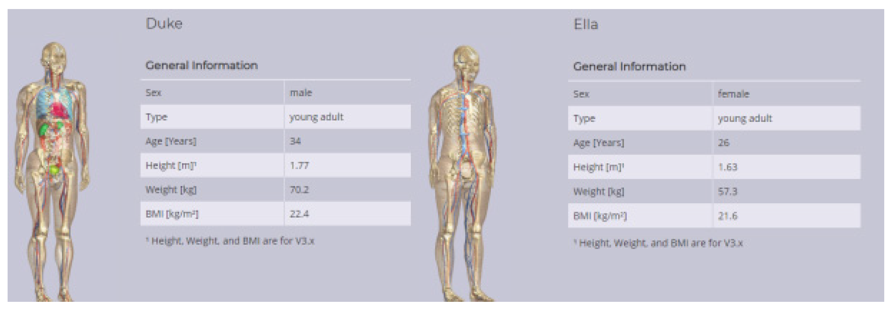
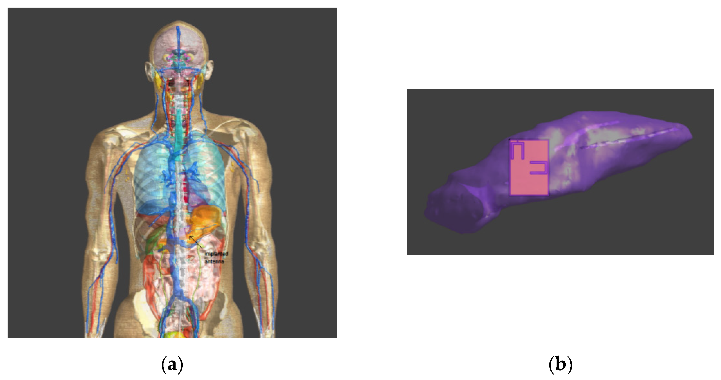
Furthermore, we studied the electromagnetic behavior of the proposed antenna when it was placed in an anatomical model that simulated the human body with all the electrical properties at the frequencies of interest and the corresponding tissue dimensions, depending on the age and sex of the anatomical model. The radiation from the antenna inside the human body and the spatial loss index, which determines the safety of the patient, were examined and characterized. The software of the company ZMT Zurich MedTech AG, Sim4Life [18] was used for the implementation of the simulation. We selected two typical anatomical models from the models ViP3.1 virtual population, as shown in Figure 20.
The pancreas is located in the terrestrial area, as illustrated in Figure 21; hence, the behavior of the antenna is mainly affected by the surrounding organs and tissues. In the simulation, there were 75 different tissues that were taken into account. Their electrical properties per frequency were obtained from the IT’IS Foundation [18].
2.3.1. Reflection Coefficient
Male Phantom
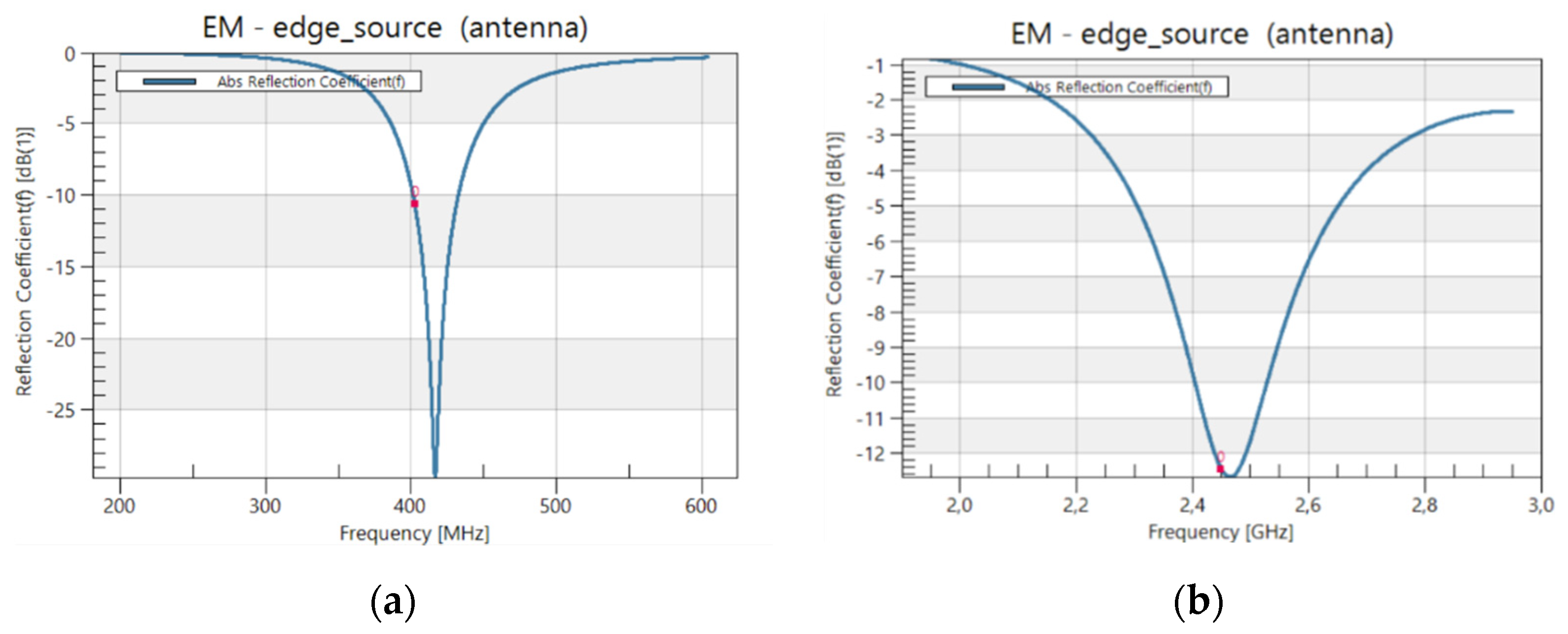
After inserting the antenna into the FDTD mesh, S11 was recalculated to verify antenna tuning to the selected frequencies (402.5 MHz, 2.45 GHz). For the male phantom, as we can see in Figure 22, the implanted antenna’s reflection coefficient was −11.9 dB at 402.5 MHz and −11.6 dB at 2.45 GHz. This value was below the −10 dB limit. As can be seen, the resonance has moved slightly. Still, because of the impedance bandwidth, 402.5 MHz and 2.45 GHz were satisfactorily covered. It should be noted though that not only changes in the environment but also different modeling techniques can affect the antenna’s simulated performance.
Female Phantom
As we see in Figure 23, the implanted antenna showed at 402.5 MHz a reflection coefficient of −10.65 dB, while at 2.45 GHz it had a reflection coefficient of −12.4 dΒ. These values were below the −10 dB limit. They were considered acceptable for the signal transmission power outside the body.
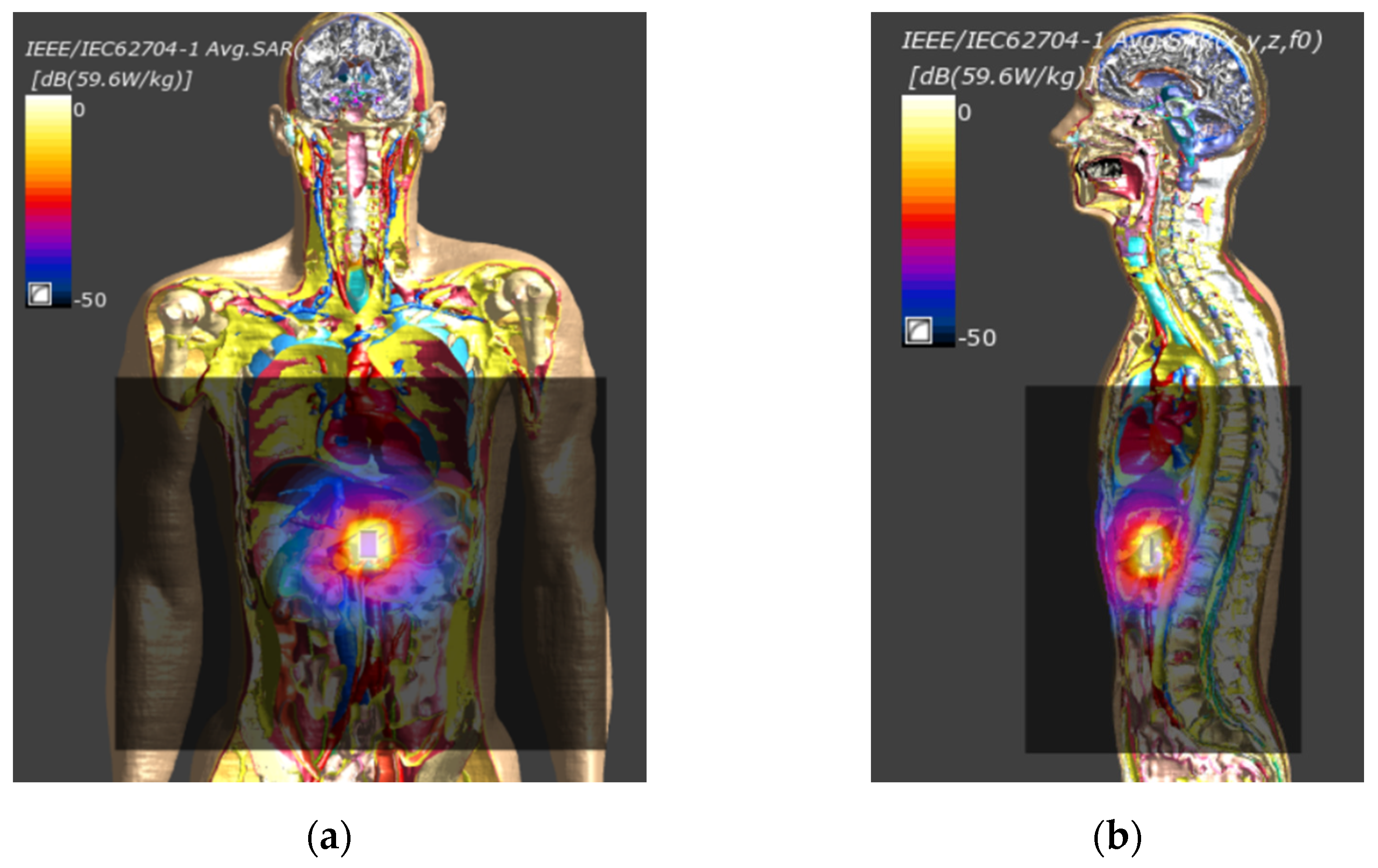
2.3.2. Specific Absorption Rate
The specific absorption rate (SAR) is the most important parameter for quantifying the electromagnetic radiation in human tissues in IEEE C95.1-2019, and [19] specified that the SAR 1 g and 10 g averages should not exceed 1.6 W/kg and 2 W/kg, respectively.
We set the input power equal to 1 W. In the male anatomical model, at 402.5 MHz the maximum SAR values for mass 1 g (pSAR1g) and 10 g (pSAR10g) were 148.38 W/kg and 59.6 W/kg, respectively. At 2.45 GHz the maximum values of SAR in mass 1 g (pSAR1g) and 10 g (pSAR10g) were equal to 217.4 W/kg and 57 W/kg, respectively. In the female anatomical model, at 402.5 MHz the maximum SAR values for mass 1 g (pSAR1g) and 10 g (pSAR10g) were 192.34 W/kg and 63.48 W/kg. At 2.45 GHz the maximum values of SAR in mass 1 g (pSAR1g) and 10 g (pSAR10g) were equal to 258.5 W/kg and 61.62 W/kg, respectively.
As we can observe, the values of SAR were high, compared against the specified limits. This was expected for 1W input power. However, for implanted sensors, antennas are expected to operate at much lower power, usually not exceeding 0 mW. As shown in the summary Table 4, the antenna was safe to use, with a maximum permissible input power (Pmax) much higher than 1mW.
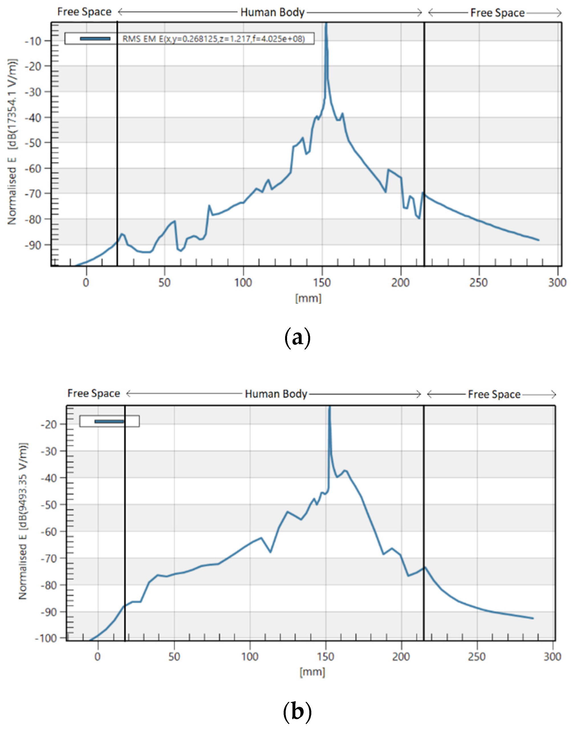
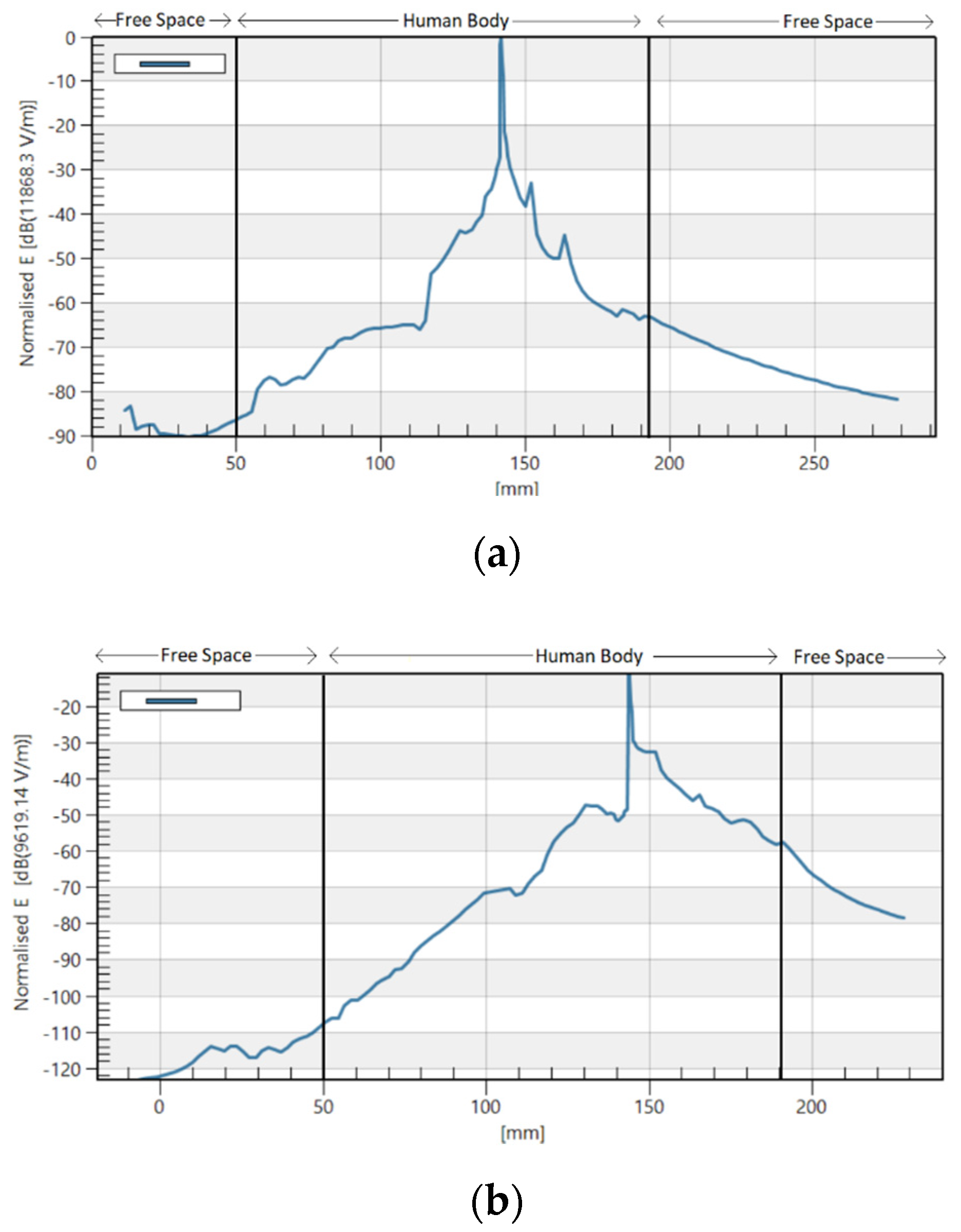
2.3.3. Electrical Field Attenuation
The attenuation of the normalized electric field when the electromagnetic wave propagated from the pancreas to the external space of anatomical model in both directions of x axis as a function of distance and when the antenna operated at 402.5 MHz and 2.45 GHz is shown in Figure 25 and Figure 26. As noted, when the electric field propagated outside the body, attenuation followed well known curves [20].
2.3.4. Total Radiated Power (TRP)
The value of total radiated power (TRP) in the male anatomical model was estimated to be −15 dBm at 402.5 MHz and −16 dBm at 2.45 GHz. In the female anatomical model TRP was calculated −9 dBm at 402.5 MHz and −14 dBm at 2.45 GHz when the input power was 1 W.
It was observed that the gain and the total radiated power (TRP) were somewhat higher in the female model. This may be due to the anatomical differences between the male and female body. In the male body, the pancreas is covered by the stomach and liver. In contrast, in the female body, the pancreas is covered only by the small intestine. Thus, the radiated power has fewer obstacles as it is propagated to the external receiver.
3. Discussion
In this paper, an implantable dual-band antenna for biomedical telemetry was designed to operate at MedRadio and ISM bands. Miniaturization and dual-band function were attained by adding a shorting pin and cutting U-shaped slots on the patch surface. The performance of the proposed antenna was evaluated inside a pancreas equivalent model, and the resonance and radiation performance were found to be within acceptable limits for an implantable device.
In addition, for a more accurate estimation of the implantable antenna behavior, the antenna was simulated and measured in the pancreas’ surface of a male and a female human phantom. As seen from the analysis of the simulation results, resonance, radiation, and patient safety performance were considered satisfactory for the desired frequencies in both human phantoms. The reflection coefficient in both cases satisfied the −10 dB limit. Nonetheless, at 402.5 MHz, there was a shift in the S11 resonance as compared with the cubic model. Finally, gain and radiated power were low due the antenna’s small size and the absorption of radiation by the tissues surrounding the pancreas, with slightly better values in the female human phantom.
The possibilities that implantable devices can offer to medicine and human body networks in general offer a variety of research perspectives. Future extensions of this work for further investigation of the wireless channel within the human body could be the following:
- Application of the proposed antenna to the other anatomical models provided by Sim4Life to study its performance and compare results.
- Extension of the wireless antenna connection study, within an anatomical model with an external receiver, inside a medical room.
- Further downsizing of the proposed antenna designed in this work, with structure modifications and algorithms.
- The construction of the proposed antenna could be carried out to study in vitro its behavior in a real environment within a liquid or gel that simulates the dielectric characteristics of human tissue. Such methods have been used in Reference [3] for exporting experimental data.
Author Contributions
Writing—original draft preparation, M.M.; writing—review and editing, S.K. (Stavros Koulouridis); supervision, S.K. (Stavros Kotsopoulos). All authors have read and agreed to the published version of the manuscript.
Funding
This research received no external funding.
Data Availability Statement
This article is an extended version of our paper [5] presented in MOCAST Conference.
Conflicts of Interest
The authors declare no conflict of interest.
References
- Kiourti, A.; Nikita, K.S. A review of in-body biotelemetry devices: Implantables, ingestibles, and injectables. IEEE Trans. Biomed. Eng. 2017, 64, 1422–1430. [Google Scholar] [CrossRef] [PubMed]
- Lee, C.-M.; Yo, T.-C.; Huang, F.-J.; Luo, C.-H. Dual-resonant Π-shape with double L-strips PIFA for implantable biotelemetry. Electron. Lett. 2008, 44, 837–838. [Google Scholar] [CrossRef]
- Karacolak, T.; Hood, A.Z.; Topsakal, E. Design of a dual-band implantable antenna and development of skin mimicking gels for continuous glucose monitoring. IEEE Trans. Microw. Theory Tech. 2008, 56, 1001–1008. [Google Scholar] [CrossRef]
- Bakogianni, S.; Koulouridis, S. A Dual-Band Implantable Rectenna for Wireless Data and Power Support at Sub-GHz Region. IEEE Trans. Antennas Propag. 2019, 67, 6800–6810. [Google Scholar] [CrossRef]
- Matthaiou, M.; Koulouridis, S.; Kotsopoulos, S. Design and Analysis of an Implantable Dual-Band Antenna for Pancreas Biotelemetry. In Proceedings of the 2021 10th International Conference on Modern Circuits and Systems Technologies (MOCAST), Thessaloniki, Greece, 5–7 July 2021. [Google Scholar]
- Bonefačić, D.; Rapinac, B. Some considerations on size reduction of a microstrip patch antenna. In Proceedings of the 2007 19th International Conference on Applied Electromagnetics and Communications, Dubrovnik, Croatia, 24–26 September 2007; pp. 3–6. [Google Scholar] [CrossRef]
- Kumar, P.; Singh, G. Microstrip Antennas Loaded with Shorting Post. Engineering 2009, 1, 41–45. [Google Scholar] [CrossRef] [Green Version]
- Moghariya, D.; Kothari, T.; Patel, P.M.P. Miniaturisation Method to Reduce the Size of Microstrip Antenna for Lower Frequency. Int. J. Sci. Res. Dev. 2013, 1, 26–28. [Google Scholar]
- Kiourti, A.; Tsakalakis, M.; Nikita, K.S. Parametric study and design of implantable PIFAs for wireless biotelemetry. Lect. Notes Inst. Comput. Sci. Soc. Telecommun. Eng. 2012, 83, 96–102. [Google Scholar] [CrossRef]
- Kim, J.; Rahmat-Samii, Y. Implanted antennas inside a human body: Simulations, designs, and characterizations. IEEE Trans. Microw. Theory Tech. 2004, 52, 1934–1943. [Google Scholar] [CrossRef]
- Clenet, M.; Shafai, L. Multiple resonances and polarisation of U-slot patch antenna. Electron. Lett. 1999, 35, 101–103. [Google Scholar] [CrossRef]
- Ghalibafan, J.; Attari, A.; Kashani, F. A New Dual-Band Microstrip Antenna with U-Shaped Slot. Prog. Electromagn. Res. C 2010, 12, 215–223. [Google Scholar] [CrossRef] [Green Version]
- Thakur, V.; Kashyap, S. Implementation and Developments of Single Feed Design using Multiple U- Slotted Patch Antenna for Wireless Applications. Int. J. Eng. Res. 2015, 4, 93–98. [Google Scholar] [CrossRef]
- Lee, K.-F.; Yang, S.L.S.; Kishk, A.A. Dual- and multiband U-slot patch antennas. IEEE Antennas Wirel. Propag. Lett. 2008, 7, 645–647. [Google Scholar] [CrossRef]
- Ansys Electronics Suite18.2; Ansys Inc.: Canonsburg, PA, USA, 2018.
- Sim4Life, Ver. 5.2.1.1375, ZMT Zurich MedTech AG, Zeughausstrasse 43, Zurich, Switzerland. Available online: https://zmt.swiss/sim4life/ (accessed on 1 October 2020).
- Huynh, T.; Lee, K.-F. Single-layer single-patch wideband microstrip antenna. Electron. Lett. 1995, 31, 1310–1312. [Google Scholar] [CrossRef]
- Hasgall, P.A.; Di Gennaro, F.; Baumgartner, C.; Neufeld, E.; Lloyd, B.; Gosselin, M.C.; Payne, D.; Klingenböck, A.; Kuster, N. IT’IS Database for Thermal and Electromagnetic Parameters of Biological Tissues. Version 4.0, 15 May 2018. Available online: https://itis.swiss/virtual-population/tissue-properties/downloads/database-v4-0/ (accessed on 1 October 2020).
- IEEE Standard for Safety Levels with Respect to Human Exposure to Electric, Magnetic, and Electromagnetic Fields, 0 Hz to 300 GHz. In IEEE Std C95.1-2019 (Revision of IEEE Std C95.1-2005/ Incorporates IEEE Std C95.1-2019/Cor 1-2019); IEEE: New York, NY, USA, 2019; pp. 1–312. [CrossRef]
- Alomainy, A.; Hao, Y.; Yuan, Y.; Liu, Y. Modelling and Characterisation of Radio Propagation from Wireless Implants at Different Frequencies. In Proceedings of the 2006 European Conference on Wireless Technology, Manchester, UK, 10–12 September 2006; pp. 119–122. [Google Scholar] [CrossRef]
Figure 1.
Proposed antenna design for pancreas implantation.

Figure 2.
Proposed Antenna Characteristics.

Figure 3.
Design of the proposed antenna.

Figure 4.
Reflection coefficient after antenna structure modifications in the MedRadio band in the pancreas model.
Figure 4.
Reflection coefficient after antenna structure modifications in the MedRadio band in the pancreas model.

Figure 5.
Reflection coefficient after antenna structure modifications in the ISM band in the pancreas model.
Figure 5.
Reflection coefficient after antenna structure modifications in the ISM band in the pancreas model.

Figure 6.
Calculated impedance of the antenna in the MedRadio band in the pancreas model.

Figure 7.
Calculated impedance of the antenna in the ISM band in the pancreas model.

Figure 8.
Surface current distribution without elements upon the patch at (a) 402.5 MHz and at (b) 2.45 GHz.
Figure 8.
Surface current distribution without elements upon the patch at (a) 402.5 MHz and at (b) 2.45 GHz.

Figure 9.
Impact of the shorting pin on the surface current distribution at (a) 402.5 MHz and at (b) 2.45 GHz.
Figure 9.
Impact of the shorting pin on the surface current distribution at (a) 402.5 MHz and at (b) 2.45 GHz.

Figure 10.
Surface current distribution with the shorting pin and one of the U-slots at (a) 402.5 MHz and at (b) 2.45 GHz.
Figure 10.
Surface current distribution with the shorting pin and one of the U-slots at (a) 402.5 MHz and at (b) 2.45 GHz.

Figure 11.
Surface current distribution of the final antenna design at (a) 402.5 MHz and at (b) 2.45 GHz.
Figure 11.
Surface current distribution of the final antenna design at (a) 402.5 MHz and at (b) 2.45 GHz.

Figure 12.
Realized gain without elements upon the patch at (a) 402.5 MHz and (b) 2.45 GHz.

Figure 13.
Realized gain with the shorting pin at (a) 402.5 MHz and (b) 2.45 GHz.

Figure 14.
Realized gain of with the shorting pin and one of the U-slots upon the patch at (a) 402.5 MHz and (b) 2.45 GHz.
Figure 14.
Realized gain of with the shorting pin and one of the U-slots upon the patch at (a) 402.5 MHz and (b) 2.45 GHz.

Figure 15.
Realized gain at (a) 402.5 MHz and (b) 2.45 GHz.

Figure 16.
Electric field distribution of the modified antenna at 402.5 MHz without structure modifications (a), after inserting the sorting pin (b), after inserting the first U-slot (c), and after inserting the second U-slot (d).
Figure 16.
Electric field distribution of the modified antenna at 402.5 MHz without structure modifications (a), after inserting the sorting pin (b), after inserting the first U-slot (c), and after inserting the second U-slot (d).

Figure 17.
Electric field distribution of the proposed antenna at 402.5 MHz displayed in two- dimensional (a) and three-dimensional space (b) as displayed from our simulations.
Figure 17.
Electric field distribution of the proposed antenna at 402.5 MHz displayed in two- dimensional (a) and three-dimensional space (b) as displayed from our simulations.

Figure 18.
Electric field distribution of the modified antenna at 2.45 GHz with no structure modifications (a), after inserting the sorting pin (b), after inserting the first U-slot (c), and after inserting the second U-slot (d).
Figure 18.
Electric field distribution of the modified antenna at 2.45 GHz with no structure modifications (a), after inserting the sorting pin (b), after inserting the first U-slot (c), and after inserting the second U-slot (d).

Figure 19.
Electric field density of the proposed antenna at 2.45 GHz displayed in two- dimensional (a) and three-dimensional space (b).
Figure 19.
Electric field density of the proposed antenna at 2.45 GHz displayed in two- dimensional (a) and three-dimensional space (b).

Figure 20.
Selected anatomical models from the ViP3.1 virtual population.

Figure 21.
Anatomical model (a) and simulation of the implanted antenna on the pancreas surface (b).
Figure 21.
Anatomical model (a) and simulation of the implanted antenna on the pancreas surface (b).

Figure 22.
Resonance performance at (a) 402.5 MHz and (b) 2.45 GHz of the male human phantom.

Figure 23.
Resonance performance at (a) 402.5 MHz and (b) 2.45 GHz of the female human phantom.

Figure 24.
Spatial distribution of SAR for 10 g tissue mass at 402.5 MHz in the male anatomical model (a) front side (b) left side extracted from Sim4Life simulation software [16].
Figure 24.
Spatial distribution of SAR for 10 g tissue mass at 402.5 MHz in the male anatomical model (a) front side (b) left side extracted from Sim4Life simulation software [16].

Figure 25.
Attenuation of electric field along the x-cut of the male human phantom at (a) 402.5 MHz and (b) 2.45 GHz.
Figure 25.
Attenuation of electric field along the x-cut of the male human phantom at (a) 402.5 MHz and (b) 2.45 GHz.

Figure 26.
Attenuation of electric field along the x-cut of the female human phantom at (a) 402.5 MHz and (b) 2.45 GHz.
Figure 26.
Attenuation of electric field along the x-cut of the female human phantom at (a) 402.5 MHz and (b) 2.45 GHz.


Table 1.
Dielectric properties of the pancreas [18].
Table 1.
Dielectric properties of the pancreas [18].
| Frequency | Relative Permittivity (εr) | Bulk Conductivity (S/m) |
|---|---|---|
| 402.5 MHz | 61.2155 | 0.8779 |
| 2.45 GHz | 57.201 | 1.968 |
Table 2.
Results of maximum Realized Antenna Gain extracted from simulations.
| Frequency | Realized Gain (dB) at 402.5 MHz | Realized Gain (dB) at 2.45 GHz |
|---|---|---|
| Without Elements | −42.4 | −24.6 |
| Shorting pin | −35 | −22.3 |
| Shorting pin and U-slot | −30.8 | −24.1 |
| Proposed Antenna | −31 | −22 |
Table 3.
Maximum Electric Field and Antenna Structure Modifications extracted from the simulations.
| Structure Modifications | Electric Field (V/m) at 402.5 MHz | Electric Field (V/m) at 2.45 GHz |
|---|---|---|
| Without Elements | 47.7 | 2501.6 |
| Shorting pin | 1007.5 | 1885.9 |
| Shorting pin and U-slot | 3554 | 4784.5 |
| Proposed Antenna | 3408.6 | 3770.6 |
Table 4.
Specific absorption rate and maximum permissible input power.
| Human Phantom | Frequency | SAR, 1 g (W/kg) | Pmax, 1 g (mW) | SAR, 10 g (W/kg) | Pmax, 10 g (mW) |
|---|---|---|---|---|---|
| Male | 402.5 MHz | 148.38 | 10.8 | 59.6 | 33.6 |
| 2.45 GHz | 217.4 | 7.4 | 57 | 35.1 | |
| Female | 402.5 MHz | 192.34 | 8.3 | 63.48 | 31.5 |
| 2.45 GHz | 258.5 | 6.1 | 61.62 | 32.4 |
Publisher’s Note: MDPI stays neutral with regard to jurisdictional claims in published maps and institutional affiliations. |
© 2022 by the authors. Licensee MDPI, Basel, Switzerland. This article is an open access article distributed under the terms and conditions of the Creative Commons Attribution (CC BY) license (https://creativecommons.org/licenses/by/4.0/).
Share and Cite
MDPI and ACS Style
Matthaiou, M.; Koulouridis, S.; Kotsopoulos, S. A Novel Dual-Band Implantable Antenna for Pancreas Telemetry Sensor Applications. Telecom 2022, 3, 1-16. https://0-doi-org.brum.beds.ac.uk/10.3390/telecom3010001
AMA Style
Matthaiou M, Koulouridis S, Kotsopoulos S. A Novel Dual-Band Implantable Antenna for Pancreas Telemetry Sensor Applications. Telecom. 2022; 3(1):1-16. https://0-doi-org.brum.beds.ac.uk/10.3390/telecom3010001
Chicago/Turabian StyleMatthaiou, Maria, Stavros Koulouridis, and Stavros Kotsopoulos. 2022. "A Novel Dual-Band Implantable Antenna for Pancreas Telemetry Sensor Applications" Telecom 3, no. 1: 1-16. https://0-doi-org.brum.beds.ac.uk/10.3390/telecom3010001