
5G Physical Layer-Based Procedure to Support Time-Sensitive Networking
by
 and
and
Faiza Bouchmal
1,*, 
Oscar Carrasco
1,
Yang Fu
1,
Jaime Rodrigo
1,
Jose F. Monserrat
2 and
and
Narcís Cardona
2 1
Casa Syetems SL, 46014 Valencia, Spain
2
ITEAM Research Institute, Universitat Politècnica de València, Camino de Vera s/n, 46022 Valencia, Spain
*
Author to whom correspondence should be addressed.
Telecom 2024, 5(1), 49-64; https://0-doi-org.brum.beds.ac.uk/10.3390/telecom5010004
Submission received: 20 November 2023
/
Revised: 31 December 2023
/
Accepted: 15 January 2024
/
Published: 24 January 2024
Abstract
:Deploying 5G in new and diverse use cases, such as Industry 4.0 and factory automation, requires 5G systems to harmonize with the communication technologies used in these industries. To this end, 3GPP Release 16 and Release 17 have made significant progress in integrating 5G systems with the IEEE 802.1 working group specifications on Time-Sensitive Networking (TSN). This paper explains a method and architecture for supporting TSN over a wireless channel in a 5G network that adds the TSN synchronization function in a Small Cell gNB implementing the TSN Translator function (SC-TT). This TSN-capable small cell provides TSN over the wireless network to synchronize UEs with the Grand Master (GM) using the physical layer signal of the 5G radio frame and the transmission of the GM reference time to provide high-precision synchronization. This paper explores the pivotal role of a Slot Indicator Signal in enhancing synchronization precision, ensuring that the UE-GM synchronization occurs within an exceptionally narrow timeframe as small as 10 ns.
1. Introduction
Advances in robotics and automation have provided highly configurable equipment with advanced features for automated manufacturing. Such features allow multiple mobile robotics to execute complex industrial processes. However, equipment capable of performing dexterous functions may require large volumes of data to be exchanged with low latency. Given such low latency requirements, wired connections have provided high bandwidth synchronization between devices, such as between the local clocks of different network components. When the local clocks of different network components are synchronized, these components can form a virtual clock domain. The virtual clock domain represents the common reference time that each local clock is synchronized to. The precision of the virtual clock domain is directly related to the uncertainty between the time measured on a local clock of a network component and the reference time of the virtual clock domain. However, in various applications, such as those that include dynamic and/or reconfigurable equipment that is mobile, wired communication may not be possible and/or it may limit the mobility and/or degree of flexibility for configuring the equipment, which can impact the use case scenarios [1,2].
Notably, 5G networks provide high bandwidths to handle high-volume data transfer that may be used to synchronize instructions between different robotic network components [3]. However, wireless communication between network components often includes additional associated delays relative to wired communication protocols that may further complicate and prevent precise synchronization between robotic network components [4,5]. For example, wireless communications may be susceptible to delays in the transmission/delivery and processing of received data. Such additional delays may compound synchronization deviations that may cause deviations between the local clock of the network component and the reference time of a virtual clock domain, thus impacting the synchronization. For example, two components operating in concert to perform an industrial process may produce costly, damaging, and/or dangerous errors when the two components work too far out of synchronization. In some applications, delays may result in errors during manufacturing or damage to the components. Thus, the speed and complexity of components in an IIOT facility may be limited based on the synchronization between the clocks of each component in the virtual clock domain. While wireless operation may be desirable, additional delays added through wireless communications can render conventional techniques inadequate for synchronizing devices using wireless communications.
It can be desirable or necessary to use critical process data in synchronized networks, such as to coordinate scheduled events between different instances of robotic equipment and/or to monitor the status of an ongoing process. Some industrial applications require accurate time information for synchronous communications. Clock synchronicity among devices is crucial, with a maximum allowed time offset within a synchronization domain ranging from less than 1 μs to 10 μs [6] depending on the specific scenario and the number of inter-communicating devices. However, as process complexity increases, so does the complexity of real-time data that may be relied on to monitor critical process data for industrial processes. For example, in addition to real-time data, other data types, such as energy data metrics and maintenance reports, may also be used in process monitoring.
The IEEE 802.1 AS protocol, known for its precise time-synchronization capabilities, holds the potential for application across various wireless technologies, like WiFi, Bluetooth, or cellular technologies. However, this paper is dedicated to delving into its specific implementation within the realm of 5G technology. By focusing on this particular context, challenges, opportunities, and implications that arise when integrating IEEE 802.1 AS into the 5G framework are discussed, including the specific aspects of a new concept of Time-Sensitive-Enabled Small Cell (TESC) and related synchronization protocols.
The structure of this paper is as follows: Section 2 provides an overview of the contemporary landscape concerning the integration of TSN within 5G networks. Section 3 offers an in-depth exploration of the TESC concept and its architectural framework. We also discuss the essential elements of TESC and the mechanisms required to maintain virtual clock domain accuracy within the TSN Slice. Section 4 focuses on the methodology for the end-to-end synchronization protocol with the new proposed mechanism. This protocol plays a pivotal role in achieving synchronization for the internal clocks of UE. Section 5 explores the innovative use of New Radio (NR) Radio Frames and the slot indicator signal to achieve synchronization within TESC and includes a discussion of the results. Finally, Section 6 draws the main conclusions of this paper.
2. Literature Review
2.1. Configuration Methods in 3GPP Standards
Enabling wireless TSN for real-time communication presents a challenge in achieving dynamic industrial automation across diverse applications like collaborative robotics, precision manufacturing, and Industry 4.0 initiatives, where TSN-enforceable communications play a key role in providing reliable scheduling and synchronization for multiple Industrial IoT applications with system controllers. A significant milestone in this pursuit is represented by Release 16, which lays a robust foundation for the seamless integration of 5G and TSN [7]. Under the umbrella of this release, 3GPP delineates the essential features of the 5G System designed to support TSN standards. Furthermore, it introduces novel entities that translate TSN protocols into internal 5G procedures. This development carries substantial practical implications, particularly in scenarios involving motion control and control-to-control communication.
In the specific context of these scenarios, a controller assumes the role of transmitting a downlink timestamp—a critical component for synchronizing one or multiple actuators tasked with the execution of precise and coordinated tasks. This synchronization, underpinned by the fusion of TSN and 5G technologies, can revolutionize the landscape of dynamic industrial automation, opening new horizons for realizing agile and responsive industrial processes.
Furthermore, Release 17 expands the integration of TSN to include uplink synchronization, where machine sensors transmit timestamps to a controller or monitoring device [8]. This use case holds significant importance, particularly in applications like smart grids, where accurate interpretation of sensor measurements is crucial. Release 18 includes new signaling messages that could allow the UE to synchronize over the air.
Thus, 3GPP has put forth three distinct configuration methods from Release 16 to Release 18 [9]:
- (a)
- 5G as a PTP instance (Release 16): The 5GS can be integrated with a PTP network as another PTP node that disseminates either the 5GS clock or an external clock. In this case, the 5GS can be configured as a PTP Boundary Clock where the 5GS is used as the time source. The 5GS maintains the timescale used in the PTP domain and synchronizes the connected PTP time receivers. Alternatively, the 5GS can be configured as a PTP Transparent Clock, which measures the time taken for the PTP event messages to travel within the 5GS, referred to as the residence time. Here, the 5GS is used to correct PTP messages.
- (b)
- 5G as a Time-Aware System (Release 17): 5GS acts as a bridge and ‘‘time-aware system’’ when integrated with IEEE TSN networks. In this scenario, the TSN domain uses its clock domain, and the Generalized Precision Time Protocol (gPTP) is used to distribute the time information from a Grand Master (GM)—the main source of time—to all the time receivers.
- (c)
- Over the Air Interface Synchronization (OAS) (Release 18): The 5G Next Generation–Radio Access Network (NG–RAN) can directly transmit epoch/Coordinated Universal Time (UTC) time to the UE via the air interface. To circumvent any confusion regarding the timing of transmission and reception, the network provides Reference Time Information (RTI) about a specific air interface event, such as a System Frame boundary, which the UE can easily identify. This RTI can be broadcast to the whole cell via the System Information Block 9 (SIB9) or dedicated Radio Resource Control (RRC) messages targeted for a single device.
Methods (a) and (b) require the incorporation of the IEEE specifications into the 3GPP; the support for (g)PTP is introduced at the edges of the 5GS. This involves the introduction of two new functional entities—the Device-Side TSN Translator (DS-TT) on the UE (User Equipment) side and the Network-Side TSN Translator (NW-TT) on the 5G network side. In the 5G Core, the configuration of the DS-TT and the NW-TT is carried out by a newly introduced function, called the TSN Application Function (TSN AF). This functionality was initially introduced in Release 16; however, in Release 17, the TSN AF was replaced by the Time-Sensitive Communication Time-Synchronization Function (TSCTSF).
The TSCTSF supports the control and configuration of the DS-TT and NW-TT and provides an additional Time-Sensitive Communication (TSC) toolbox for enhanced functionality such as Quality of Service (QoS).
3GPP has proved to be of special interest for method (c), which focuses on the direct monitoring and reporting of timing synchronization status over the air interface. A dedicated key issue has been included in Technical Report (TR) 23.700-25 [10] to address this. The study’s conclusion proposes an approach that involves the gNB sending a status report ID in the SIB to notify UEs of new RAN timing synchronization status reports. UEs can actively retrieve the information by transitioning to the RRC_Connected state or using the report ID as an index to automatically determine the synchronization status. Additional time-synchronization characteristics can be provided to UEs or AFs through Service Level Agreements (SLAs) or dedicated signaling. Thus, the report ID allows UEs to be aware of the availability of new information and prompts them to take action to retrieve the relevant timing synchronization status report from the network. However, the main limitation of this proposal is that the accuracy might be limited to 5–10 μs [11]. Besides this, method (c) does not support external time domains such as TSN.
The authors of [12] explore the integration of 5G and TSN in smart manufacturing, focusing on the synchronization requirements for industrial automation. They discuss the current state of 5G’s support for time synchronization and integration with TSN and highlight Release 16 and Release 17 work refining the time-synchronization protocol in 5G. This integration is evaluated in [13], where the authors develop an analytic framework to assess the accuracy of over-the-air time synchronization; the study concludes that this accuracy may be affected by factors such as clock drift, air-interface timing errors, reference time granularity, and synchronization frequency. Moreover, the authors of [14] add that the key challenge in achieving accurate time synchronization in integrated 5G and TSN networks is the disparity between a traditional TSN transparent clock and the 5G System emulating a transparent clock. This can result in synchronization errors, even with small frequency offsets between the ingress and egress of the 5G System. In order to address this challenge, these authors proposed that future research can focus on minimizing the impact of syntonization errors between 5G devices on time synchronization in integrated 5G-TSN networks.
2.2. Contribution to the State of the Art
While all the proposed solutions thoroughly investigate synchronization, focusing on accommodating TSN-capable IoT devices, addressing a critical aspect of the IoT landscape is essential. What about the existing IoT devices that are already deployed and lack TSN support? This is a pertinent question as many real-world industrial environments consist of a mix of legacy and modern IoT devices. Balancing synchronization strategies to cater to TSN-capable and non-TSN IoT devices becomes imperative for achieving comprehensive and practical synchronization solutions.
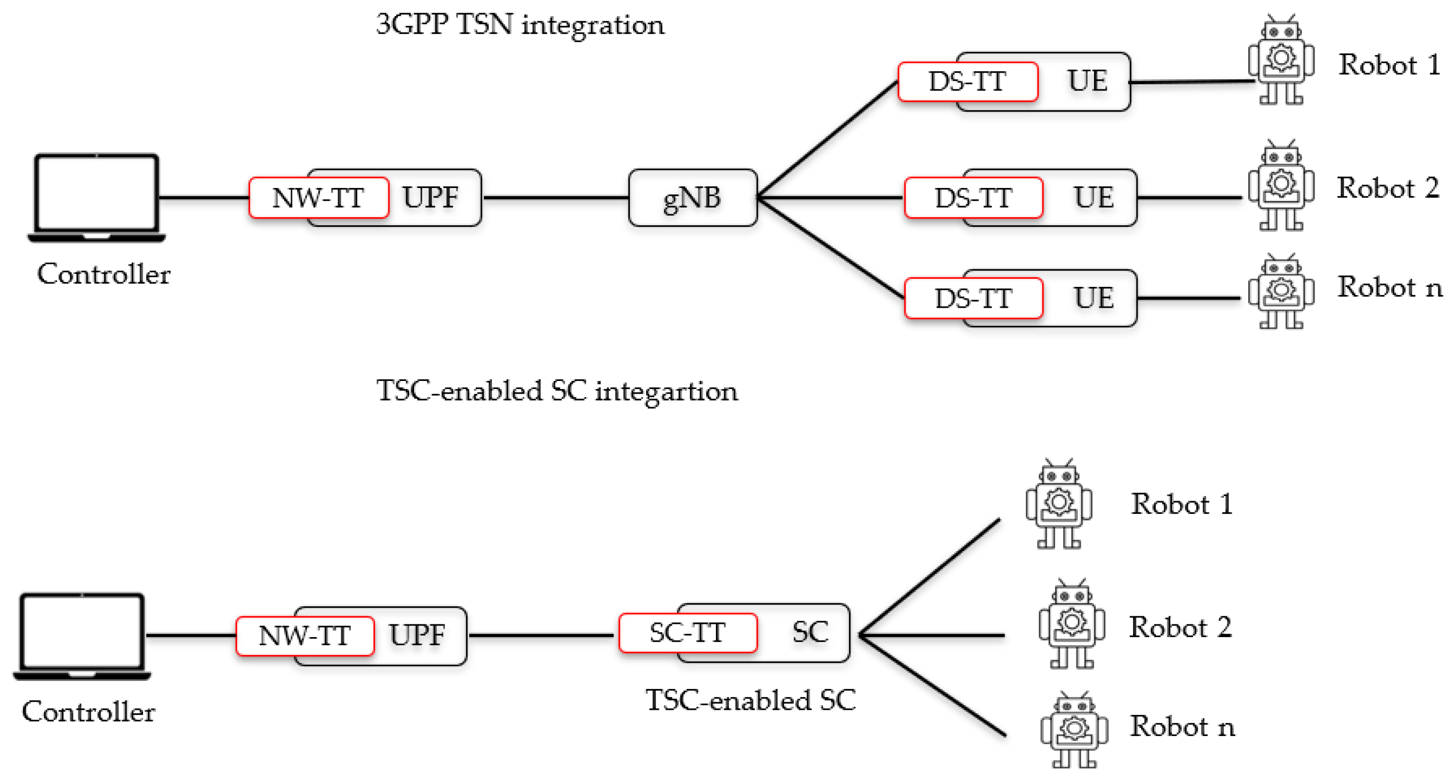
This paper presents a method and architectural framework designed to enable TSN functionality over a wireless channel within a 5G network. The approach involves incorporating TSN synchronization capabilities into a Small Cell gNB, effectively implementing what is known as the Small Cell TSN Translator function (SC-TT). This TSN-capable Small Cell provides TSN functionality over the wireless network, facilitating the synchronization of UEs with the Grand Master (GM). This synchronization is achieved by utilizing the 5G radio frame’s physical layer signal as a flank for the clock adjustment while the absolute time reference is given by the transmission of the GM reference time over the air, as specified by Release 18. In such a scenario, the Small Cell can synchronize its clock with the TSN domain by acting as a gPTP slave device; it receives gPTP synchronization messages from the gPTP GM clock in the TSN network and adjusts its local clock accordingly. The synchronization messages contain timing information, such as the current time and synchronization correction values, which the Small Cell uses to align its clock with the TSN domain. Once the Small Cell is synchronized, it uses the physical layer signal of the 5G radio frame to provide high-precision synchronization to the UE. This integration is exemplified in Figure 1, where the TESC includes the Small Cell TSN Translator (SC-TT) responsible for translating TSN messages into 5G signaling. This integration simplifies TSN synchronization for Small Cell manufacturers and facilitates the expansion of their market into automated factories. Additionally, it minimally impacts 5G IoT UE, making highly accurate TSN-capable IoT devices feasible, utilizing low-cost local oscillators, and extracting time and synchronization information from the 5G Radio Frame through slot indication and symbol boundary signals.
Drawing from the analysis of the current state of the art, the precision of Over-The-Air synchronization (OAS) is contingent upon the type of device. For UE equipped with PTP support, the precision level is achieved at less than 1 μs. Conversely, low-cost and low-energy UEs lacking PTP support can ensure an accuracy level of less than 10 μs [10,11,12,13]. Employing TESC ensures an accuracy level within the range of 0.01 μs to 1 μs, even for economical and energy-efficient UEs lacking PTP support. Table 1 provides a summary of this comparison. Section 4 and Section 5 explain how this accuracy is calculated.
3. Time-Sensitive-Enabled Small Cell
3.1. Concept and Architecture
As described above, providing a wireless TSN network poses some challenges. Implementations that use a dedicated TSN system, separate from the primary wireless network, may increase the complexity and cost of the UEs. To address such challenges, we develop a physical-layer procedure that disciplines the device clock using a timing signal extracted from the 5G NR radio frame sub-slot or Orthogonal Frequency Division Multiplexing (OFDM) symbol to achieve the desired synchronization accuracy. In some specific implementations of the proposed idea, the SC-TT embedded in the Small Cell (SC) is a gPTP instance that guarantees the synchronization and the accuracy of the 5G NR radio frame to maintain enforcement of the synchronization across the 5G industrial network.
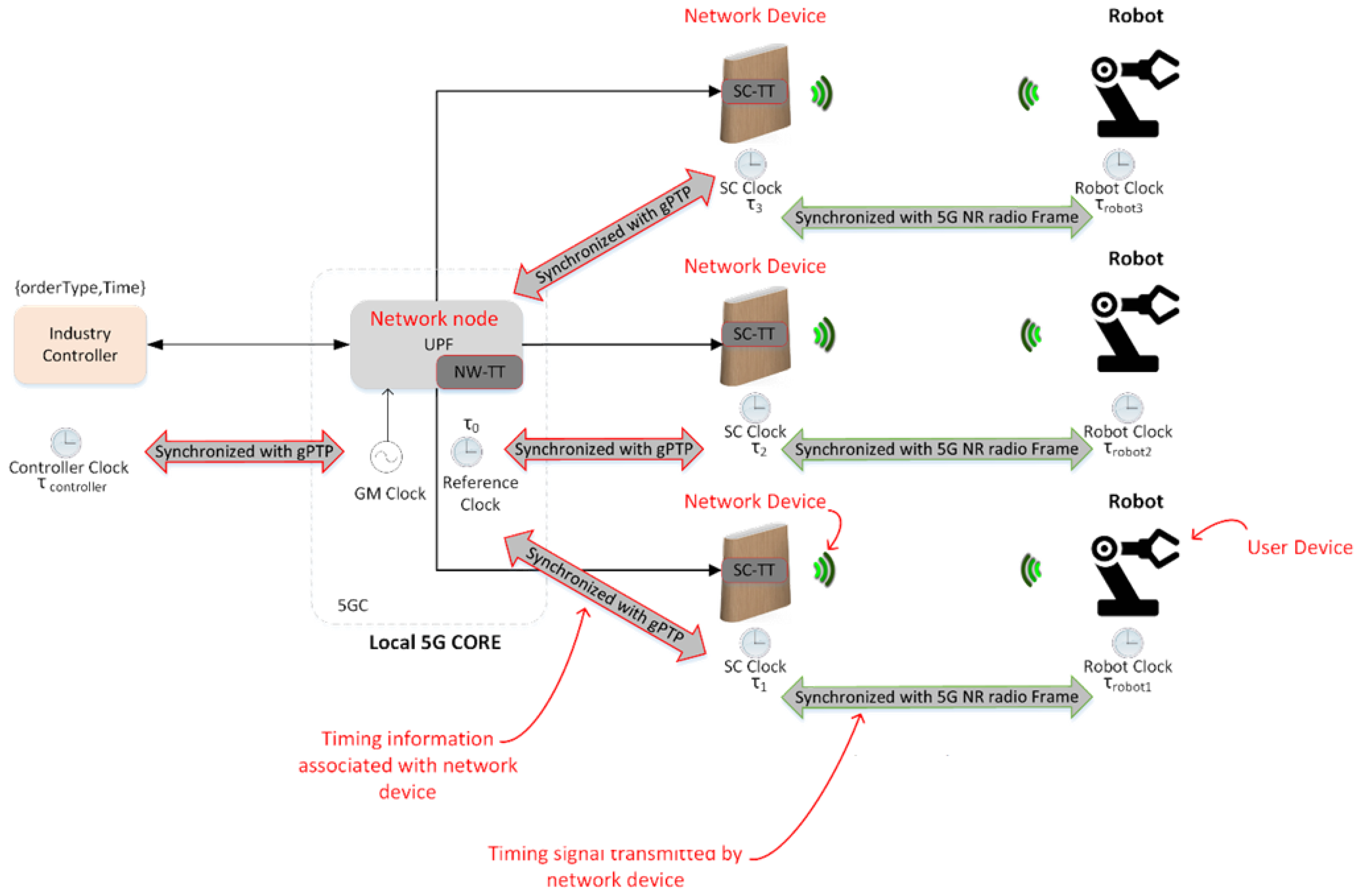
Figure 2 illustrates a private industrial network that contains multiple small TSC-enabled Small Cells (TSC-SCs): The three SCs communicate with the UPF to access the internet and industry controller; each TSC-SC may provide wireless connectivity to multiple equipment instances; the Network TSN Translator (NW-TT) interfaces the 5G and internet systems; and equipment instances (robots) wirelessly communicate with SCs. The arrows in red highlight the sycnrhonization using gPTP, while the arrows in green highlight the synchronization using 5G NR radio frame.
Network components have a local clock for local timekeeping. The local clocks may all be synchronized to a reference clock to provide a common understanding of time across the network components, forming a virtual clock domain. For example, a grand master clock may provide a time from an atomic clock, such as an atomic clock affiliated with the GPS or a national timekeeping system. The controller clock is synchronized with the reference clock and provides the Controller with a local time, which may be used in scheduling events or interpreting incoming signals.
As shown in Figure 2, SC clocks are synchronized with the reference clock, and UE clocks are synchronized with SC clocks. The synchronization of the UE clocks with an SC clock, and synchronization between the SC clock and the reference clock, provides synchronization between the UE clocks and the reference clock. In this way, each clock in the virtual clock domain has a common reference time. Thus, when the Controller schedules instructions for the robots to coordinate an assembly process, all the robots will be able to execute their respective portions of the assembly process at the prescribed time without interfering with each other.
The SC that provides access for UEs to the core network may communicate with other network components through wired connections and communicate with the UEs through wireless connections. For example, in Figure 2, the small cells and industry controller are each wired to the UPF, as indicated by the solid lines; the small cells wirelessly communicate with equipment instances (robots), as indicated by the three-arc wireless symbol; the wired connection may communicate using an Ethernet protocol; and the wireless connections may communicate through 5G or beyond 5G. Thus, network components that communicate through wired connections may be synchronized through a first-timing protocol using gPTP [14], and network components that communicate through wireless connections may be synchronized through a second-timing protocol based on using a 5G NR radio frame as explained in Section 4 and Section 5.
3.2. Virtual Clock Domain Accuracy and TSN Slice
A virtual clock domain enables the coordination of independent clocks across the network nodes to provide a distributed common timescale with defined accuracy. The accuracy of a virtual clock domain is based on the uncertainty of each clock relative to the reference time. Figure 3 illustrates a virtual clock domain including controllers, SCs, and Robots.
The controller clock is synchronized with the reference clock and provides a controller with a local time, which may be used in scheduling events or interpreting incoming signals. SC clocks are synchronized with the reference clock. Robot clocks are synchronized with SC clocks and, by extension, the reference clock. In this way, each clock in the virtual clock domain has a common reference time.
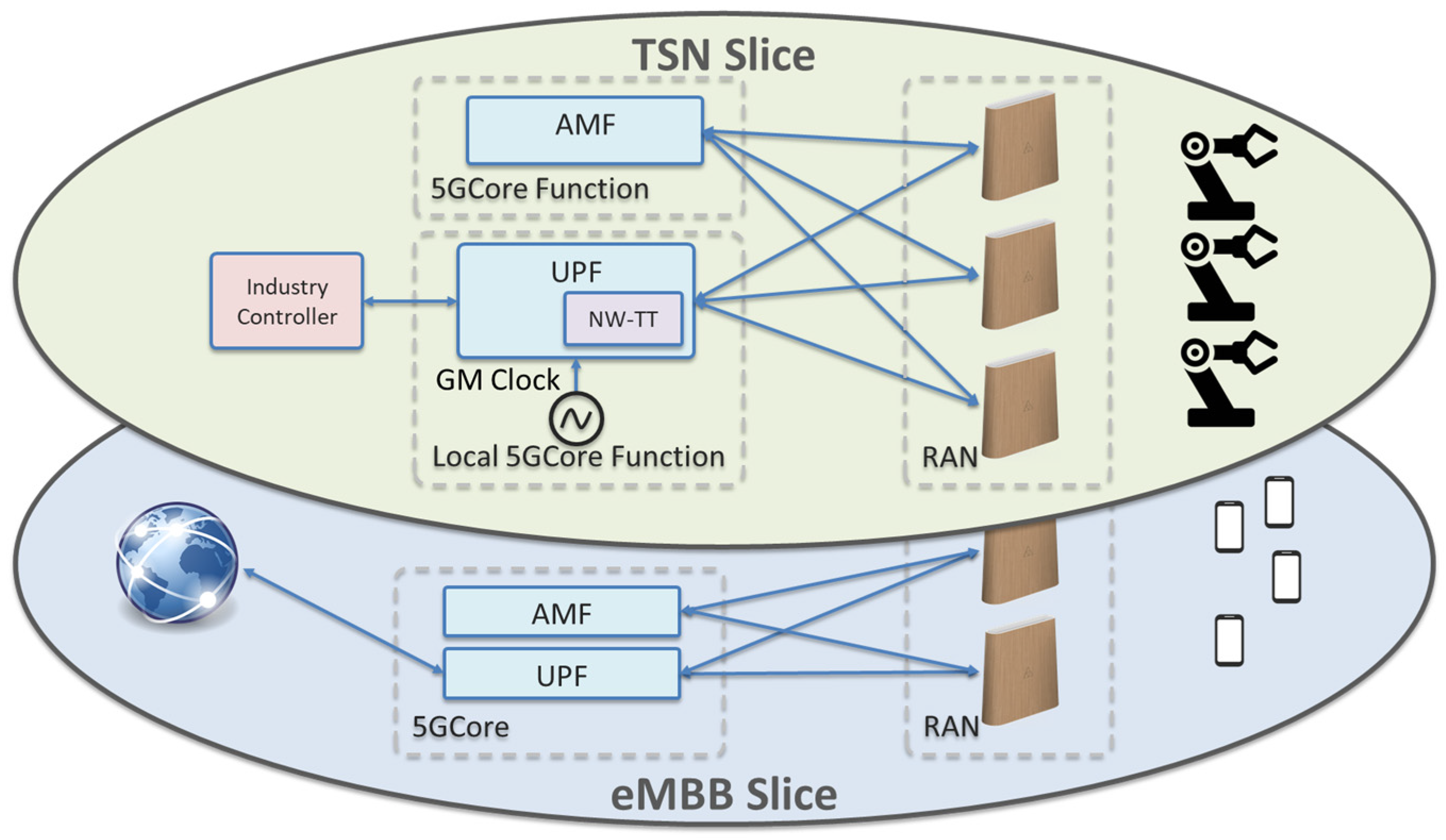
In connection with providing TSN functionality, the network should provide message delivery with guaranteed delivery of the time-constrained messages or signals. Quality of Service (QoS) policies may be implemented to prioritize the performance of different types of traffic from different UEs to guarantee message delivery. In our proposal, the QoS may be implemented by deploying a dedicated Network Slice. Network Slices are isolated, virtual end-to-end networks configured to fulfill specific parameters or requirements. For example, a network slice may be configured to provide specific QoS requirements regarding the latency and reliability of the TSN application.
Figure 4 illustrates a network including a dedicated virtual TSN slice. For this, resources from the AMF and the UPF may be dedicated to the virtual TSN slice. Moreover, network resources that provide access to the AMF and the UPF may allocate dedicated resources to the separate network slices providing different services. Virtual network slices may be implemented by dedicating a portion of computing capacity to provide a dedicated function or service to devices communicating with the network slice. Here, the TSN slice may be deployed together with a standard network slice to support the standard 5G smartphones and UEs. For example, the TSN slice may include dedicated resources from the AMF and the UPF to provide functionality to the robots. Additional AMF and UPF resources may be allocated to a virtual eMBB slice. The eMBB slice provides 5G network communication to smartphones.
4. End-to-End Synchronization Using TESC
To achieve end-to-end synchronization, our method is divided into two distinct parts. The first part initiates at the Grand Master (GM) clock, the main reference clock, and concludes at the SC. This phase closely aligns with the proposal outlined in 3GPP Release 17 and follows a similar procedure. However, the key distinction lies in terminating the gPTP flow at the SC rather than at the UE. The second part of the synchronization process focuses on the interaction between the SC and the UE. From the perspective of the UE, the SC assumes the role of the primary timing source, providing essential timing information utilizing the NR Radio Frame.
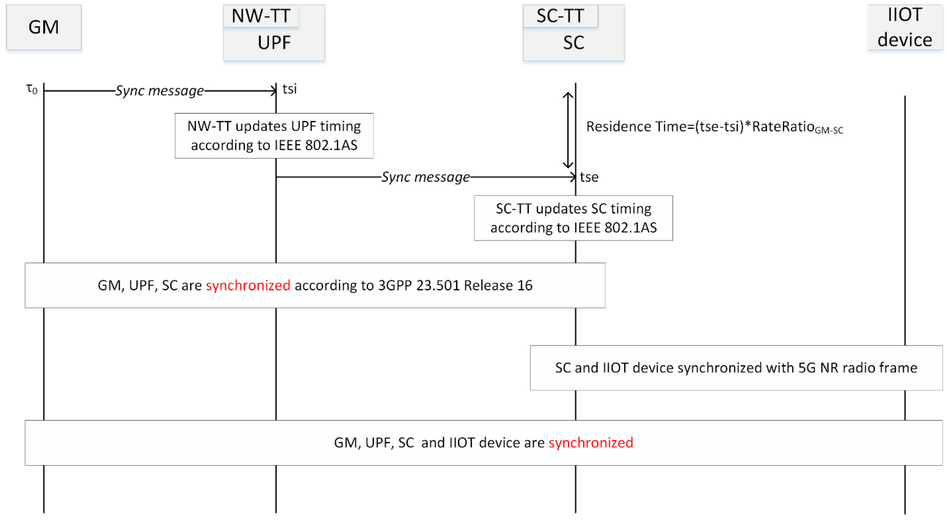
Figure 5 illustrates an end-to-end synchronization process for the synchronization of an industrial IoT UE with a GM clock. The UPF may include a NW-TT for encoding timing signals following a 5G network protocol by 3GPP Release 16 and Release 17. Moreover, the SC may include the SC-TT to decode timing signals from the UPF and synchronize the UE to the reference time of the GM.
4.1. Synchronization of the Internal Clock of the Small Cell: TSN-Based Synchronization
The synchronization process from the GM to the SC involves exchanging gPTP messages, such as Sync and Follow_Up messages, between the SC and the gPTP GM clock. These messages carry timing information and are used to calculate the clock offset and clock drift between the SC and the TSN domain. The SC adjusts its local clock based on the received timing information to achieve synchronization with the TSN domain.
In Figure 5, the UPF receives a Sync message from the GM. Using this message, the UPF implements a first-timing protocol to synchronize the UPF with the SC, whereas NW-TT and SW-TT implement a synchronization protocol following a Precision Time Protocol. For example, NW-TT and SC-TT may implement synchronization using the IEEE 802.1AS standard [15]. The 5G network may be transparently integrated with the TSN network. The integration between the 5G network and the TSN network may be implemented as a bridge in accordance with IEEE 802.1 standards [16,17]. Thus, the UPF uses a Sync message to update the local clock at the UPF, and NW-TT updates the UPF timing according to IEEE 802.1AS while the GM may directly communicate with the UPF. If the network includes multiple UPF facilities, the UPF may indirectly receive a Sync message from the GM through an intermediary UPF.
As described above, in connection with Figure 5, the first timing protocol, implemented using the NW-TT and SC-TT, may treat the SC as the endpoint of the TSN timing domain. For example, the synchronized time at the SC in the first timing protocol may be represented by the following equation:
where τsc is the synchronized time of the SC; τ0 is the reference time, received from the GM; δLink delay is the propagation time of the packet, including the sync message, through the cable from the GM to the NW-TT; and Tresidence is the residence time between the UPF and the SC expressed in the GM time base. The link delay may be calculated according to the IEEE 802.1AS standard. The residence time is measured using ingress timestamps (tsi) and egress timestamps (tse). For example, the tsi is recorded when a sync message is received at the UPF, and tse is recorded when a sync message is received at the SC. The residence time may be represented by the following equation:
where the RateRatio is the ratio between the frequency of the GM clock and the SC’s local clock. The RateRatio may be determined according to the IEEE 802.1AS standard. Therefore, the GM, UPF, and SC are synchronized according to 3GPP 23.501 Release 16 for downlink synchronization and 3GPP 23.501 Release 17 for uplink synchronization.
τsc = τ0 + δ(link delay) +Tresidence,
Tresidence = tse − tsi × RateRatio,
4.2. Synchronization of the Internal Clock of the UE: Physical Layer-Based Synchronization
The SC determines a timing adjustment based on the timing information, including the packet reference time and residence time, as they are transmitted from a GM clock to the SC. The residence time is further described above in connection with Figure 5. Also, the timing information includes a Timing Advance (TA), which is the time for the Reference Signal to travel from the SC to the UE’s receiver. TA may be determined using the Random-Access process. Thus, from the timing information, a virtual clock domain time is determined at which the UE will receive the radio frame transmitted from the SC. The Synchronization Time represents the time—in the virtual clock domain—when the radio frame will arrive at the UE. The Synchronization Time is further described in Section 5.
The SC adjusts a timing signal of the radio frame to adjust the timing of the UE clock. This timing signal may be a physical layer signal as, for example, a slot indication signal or a symbol boundary signal. The SC transmits the slot indication signal such that it arrives at the UE at an even timing interval of the reference time. This enables the UE to maintain precise synchronization with the reference clock between slot indication signals by using its accurate internal clock. The timing signal received by the UE is combined with a timing feedback circuit to adjust the internal clock flank of the UE. The feedback circuit is configured to adjust the timing of the internal clock flank such that the flank is coincident with subsequent timing signals. The synchronization of the UE clock to the virtual clock domain using a physical layer signal of the wireless network is detailed in the next section.
This paper presents an innovative approach that harnesses the slot indicator signal transmitted at the start of each frame to achieve precise synchronization, in line with our research findings. This slot indicator signal plays a crucial role as a cornerstone of the timing system. By strategically addressing issues related to path-delay estimation and time-of-arrival estimation errors, our method optimizes the slot indicator signal’s utility. Furthermore, our research underscores the significance of enhancing the granularity of reference time, a factor proven to reduce synchronization errors effectively. Additionally, we emphasize the importance of optimizing synchronization frequency to ensure the slot indicator signal’s periodic transmission is leveraged to the fullest extent. This comprehensive approach not only aligns with our research outcomes but also reinforces the feasibility of meeting synchronization requirements of less than 1 μs [6,13,18] or better in integrated 5G and TSN systems.
5. Using The 5G Physical Layer Signal for TSC Synchronization
Using the 5G physical layer slot indication signal for TSN synchronization is the main proposal of this paper. It represents a novel approach to achieving accurate time coordination in a wireless network independently of the end terminal capacities. This method involves a SC base station, which includes a gPTP instance that guarantees the synchronization and accuracy of the 5G NR radio frame. The SC then transmits a timing signal to the UE using the 5G NR radio frame. This timing signal includes both the synchronization and reference times. The UE receives this timing signal and uses it to synchronize its local clock with the SC clock. The SC handles this synchronization process, and the UE extracts the time and synchronization from the 5G NR radio frame.
5.1. Using the Physical Layer Slot Indication Signal with a Time-Locked Loop (TLL) for Enhanced Synchronization Precision
The symbols within a slot may be configured as downlink, uplink, or flexible (i.e., uplink or downlink) symbols. A slot indicator signal may be transmitted to the UE to specify the symbol allocation within each slot using the Downlink Control Information (DCI) protocol. The slot indicator may include an indication of the periodicity of the symbols configured in a downlink–uplink pattern, several consecutive full downlink slots at the beginning of each downlink–uplink pattern, several consecutive downlink symbols at the beginning of a partially-filled slot, several consecutive full uplink slots at the end of each downlink–uplink pattern, and/or several consecutive uplink symbols at the end of a partially-filled slot. Moreover, the slot indicator may be configured following other formats to provide the UE with an indication of slot and/or symbol usage.
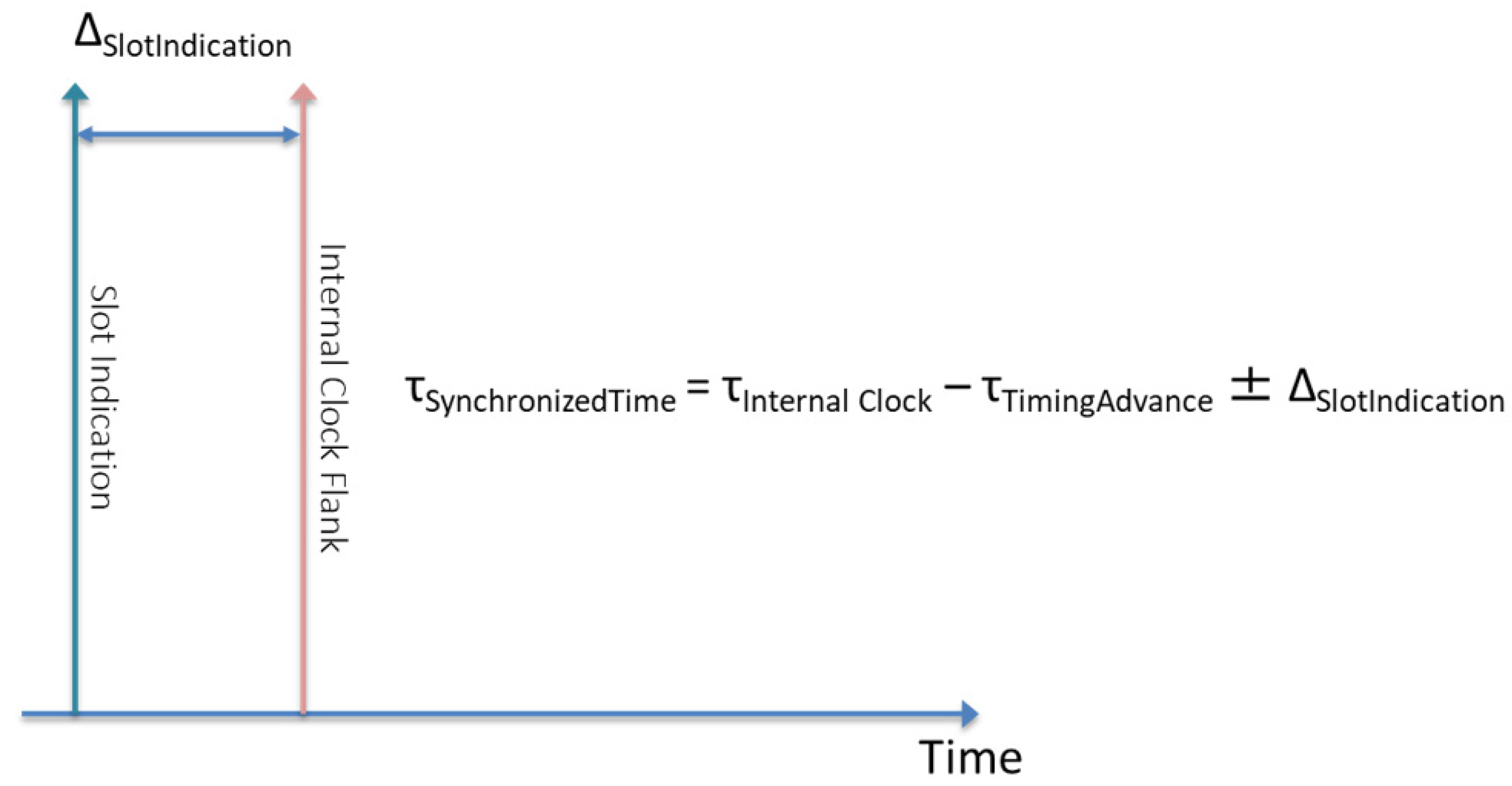
The SC may transmit the slot indication signal such that the arrival of the slot indication signal corresponds with a flank signal of the SC clock. Figure 6 illustrates a schematic of the timing between the SC clock flank signal and subframes of the radio frame. Thus, the UE may calculate the synchronized time according to Equation (3):
where τSynchronizedTime is the synchronized time in the UE, τInternal Clock is the time kept by the internal clock of the UE, τTimingAdvance is the timing advance value received from the SC, and ΔSlotIndication is the difference between the arrival time of the slot indication signal at the UE and the reference time. The synchronized time maintains synchronization with the reference clock between the slot indication signals.
τSynchronizedTime = τInternal Clock − τTimingAdvance ± ΔSlotIndication,
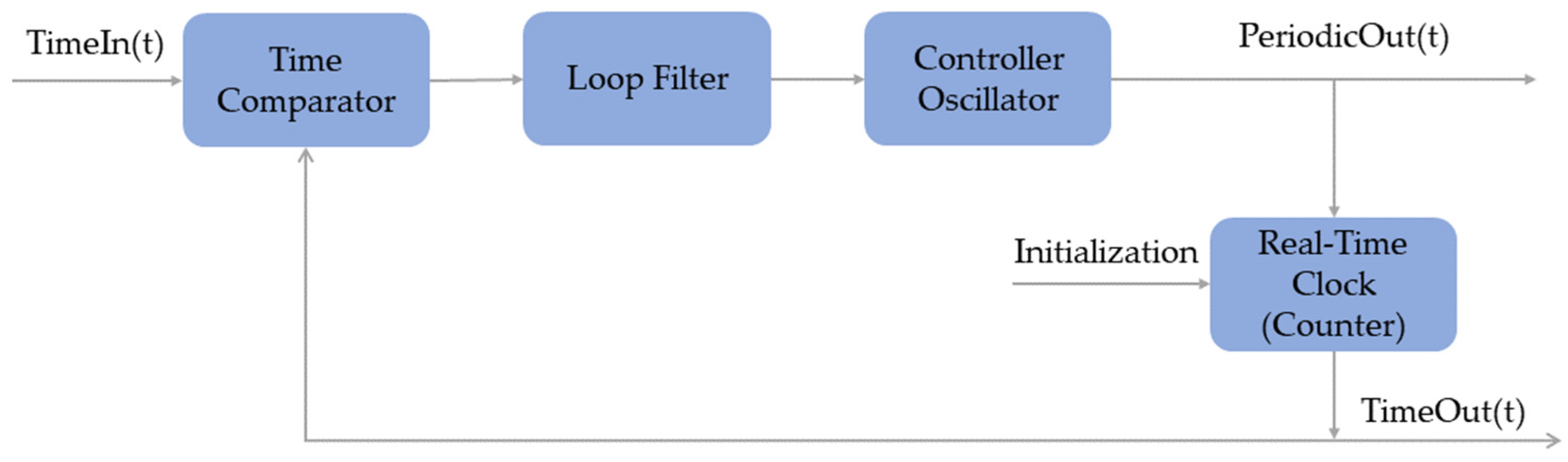
In this context, it is noteworthy to introduce the Time-Locked Loop (TLL) system, a specialized circuit designed for phase alignment and synchronization purposes, offering distinct advantages over traditional Phase-Locked Loops (PLLs). Unlike PLLs, the TLL operates in the time domain, making it ideal for applications where precise timing alignment is paramount. Thus, the TLL system can execute synchronization with the reference clock of the virtual clock domain; it effectively adjusts the internal clock of the UE to ensure synchronization with the received timing signals. Figure 7 illustrates a TLL feedback circuit, which contains the following elements:
- Controlled Oscillator: This component generates periodic timing signals.
- Real-Time Clock (Counter): This counts time based on the periodic timing signals from the controlled oscillator and produces a time-out signal.
- Time Comparator: This compares the computed time-out signal with a reference time-in signal.
- Loop Filter: The result of the comparison from the time comparator is filtered and then provided as feedback to the controlled oscillator.
The main advantages of using the proposed TLL circuit are:
- High Precision: The primary advantage of this TLL is its ability to achieve extremely high synchronization precision, down to 1 ns in specific scenarios [15]. This level of precision is critical for meeting the stringent timing requirements of 5G networks.
- Time Domain Operation: Unlike traditional Phase-Locked Loops (PLLs) that work in the phase domain, the TLL operates in the time domain. This makes it well-suited for applications where precise timing alignment is more important than phase alignment.
- Mitigation of Timing Variations: The TLL can correct for signal arrival-time variations due to signal propagation delays and clock drift; it monitors and adjusts the clock to mitigate these variations, ensuring reliable synchronization.
5.2. Improving Synchronization Precision with Slot Indication in 30 kHz Subcarrier Bandwidth
To provide synchronization with the reference time, the SC transmits the slot indication such that it arrives at an even timing interval of the reference time. For example, when the subcarrier spacing is 30 kHz, the slot duration is 500 µs and a new slot indicator is transmitted every 500 µs. In the illustrated example of Figure 8, the time format is hours:minutes:seconds:milliseconds microseconds nanoseconds. The slot indicators are transmitted such that they arrive at the UE when the reference time is an integer multiple of 500 µs. Slot indication signal [SL#0], for instance, arrives at the UE when the reference time is 16:30:23:000 000 000; slot indication signal [SL#1] arrives at the UE when the reference time is 16:30:23:000 500 000, 500 microseconds later, and so on.
The enforcement of the arrival time of the indication signals enables the UE to maintain precise synchronization with the reference clock between slot indication signals by using the precise internal clock, used to maintain frequency and phase synchronization. Here, the UE may use every slot indication signal to check and/or adjust the synchronization of the UE clock using one or more slot indication signals per radio frame. The degree of drift of the UE clock relative to the reference time, the distance from the UE to the SC, the velocity of the UE, and the particular process being executed by the UE may factor into determining how frequently to check and/or adjust the synchronization of the UE clock using one or more indication signals.
When a 60 kHz, 120 kHz, or 240 kHz subcarrier spacing is used, the respective subframes will have 4, 8, or 16 slots. Thus, the regularity of the slot indicator signal depends on the subcarrier spacing. For example, when the subcarrier spacing of 15 kHz is used, the slot indication signal is sent every 1 ms. In contrast, when we use 240 kHz, the slot indication signal is sent every 62.5 µs, which can provide higher precision. The level of precision attainable with this synchronization method depends on the subcarrier spacing utilized, making it a versatile and adaptable solution for 5G network synchronization needs.
5.3. Performance Evaluation
Numerical evaluations were conducted to assess the performance of Over-the-Air time Synchronization (OAS) using the method proposed in this paper. For these results, we have used 3GPP-defined values of UE timing errors, given by [18], ensuring that the UE can afford up to +/−0.1 ppm relative error, which is 0.2 µs clock drift per second assuming errors in both sides of the communication. Under this assumption, the network would only need to deliver the GM reference time at most every 5 s to remain within the 1 µs accuracy requirement. Moreover, the reference time granularity is 10 ns [13], which means that, once the UE gets a message containing the reference time GM, it gets its maximum accuracy that would start degrading at a pace of 0.2 ns per millisecond. In the analysis, the UE could synchronize every slot, via the Slot Indicator Signal, or could synchronize after several slots.
Figure 9 plots the UE’s synchronization accuracy depending on the Slot Indicator Signal period or, in other words, depending on how often the UE performs the synchronization process using the TESC. If the synchronization is made every slot, the accuracy would remain at 10 ns, but if the period of synchronization increases, after 50 ms, the drift would start affecting the accuracy. In the limit, if no resynchronization is made in any slot, the clock drift would reach 1 µs in 5 s, in which a new reference time would be provided to the UE in the application layer.
According to the results, when using TSN-enabled Small Cell we can maintain the most accurate clock, at 10 ns, which is required in scenarios such as coordinated maneuvering of autonomous vehicles, industrial automation in high-speed production lines, healthcare telesurgery, and AR gaming.
Next, the impact of the number of UEs to be synchronized to the GM on the consumption of Resource Blocks (RBs) was evaluated. We considered 5G numerology with SCS 15 kHz and 10 MHz bandwidth configurations, which entailed a maximum number of RBs per slot of 52, yielding 260,000 RBs every 5 s [19]. Assuming that the GM reference time can be encoded in 76 Bytes [15], this is equivalent to 4 RBs using a Quadrature Phase-Shift Keying (QPSK) modulation scheme with ½ code rate.
Figure 10 illustrates the rate of RB consumption as a function of the number of users in a cell. With the TESC proposal presented in this paper, only 0.0015% of the RBs are allocated to broadcast the GM reference time, transmitted once every 5 s to all UEs in the cell, and this rate remains constant regardless of the number of UEs. Consequently, this option proves highly advantageous in scenarios where the number of UEs is high and they require an accuracy level of less than 1 µs. Conversely, in a conventional 5G system with an accuracy level of 1 µs, the consumption of RBs increases as more UEs require synchronization. Furthermore, in a 5G system designed for 10 ns accuracy, the RB consumption rate experiences a rapid increase as the number of UEs grows, since the GM reference time has to be sent every 50 ms to every UE.
6. Conclusions
This paper has comprehensively explored the integration between 3GPP 5GS and TSN focusing on the advancements introduced in Releases 17 and 18. A significant breakthrough in this paper has revolved around a pioneering approach that places synchronization accuracy at its core while maximizing the utility of the slot indicator signal. The slot indicator signal has emerged as a critical component in achieving precise synchronization.
A key innovation has been introduced, incorporating the strategic deployment of the TSN Translator (SC-TT) within the SC instead of placing the loan of synchronization on the UE side. This novel approach revolutionizes the synchronization paradigm, improving synchronization accuracy within the range of 0.01 μs to 1 μs. This transformative use of the TSN translator at the SC level showcases the potential to expand the SC market and accelerate the deployment of the Industrial Internet of Things.
In the conducted numerical evaluations of the proposed method, adherence to 3GPP-defined values of UE timing errors was ensured, allowing for a permissible error range of up to +/−0.1 ppm (0.2 µs clock drift per second). The analysis revealed that synchronizing the UE in every slot maintained an accuracy of 10 ns, while longer resynchronization periods led to the drift affecting accuracy after 50 ms. TESC usage showed the ability to sustain the most accurate clock (10 ns) required for specific industrial applications. Additionally, the evaluation considered the impact of the number of UEs synchronized to the GM on RB consumption; with the proposed method, only 0.0015% of the RBs were allocated to broadcast the GM reference time every 5 s, maintaining a constant consumption regardless of the number of UEs. This proved advantageous in scenarios with a high number of UEs requiring sub-1 µs accuracy, contrasting with conventional 5G systems where RB consumption increases with the number of devices to be synchronized.
Author Contributions
Conceptualization, F.B., O.C. and J.F.M.; methodology, F.B., O.C. and J.F.M.; software, F.B., O.C. and J.F.M.; validation, F.B., O.C. and J.F.M.; formal analysis, F.B., O.C. and J.F.M.; investigation, F.B., O.C., J.F.M., Y.F. and J.R.; resources, F.B., O.C., J.F.M. and N.C.; data curation, F.B., O.C. and J.F.M.; writing—original draft preparation, F.B., O.C., Y.F., J.R., J.F.M. and N.C.; writing—review and editing, F.B., O.C. and J.F.M.; visualization, F.B., O.C. and J.F.M. All authors have read and agreed to the published version of the manuscript.
Funding
This research received no external funding.
Data Availability Statement
Data are contained within the article.
Conflicts of Interest
Authors Faiza Bouchmal, Oscar Carrasco, Yang Fu and Jaime Rodrigo were employed by the company Casa Syetems. The remaining authors declare that the research was conducted in the absence of any commercial or financial relationships that could be construed as a potential conflict of interest.
References
- Smith, J.; Johnson, K. The Impact of Robotics and Automation on Manufacturing Processes. J. Ind. Technol. 2020, 35, 123–145. [Google Scholar]
- Lee, H.; Kim, Y. Challenges and Solutions in Synchronizing Network Components in Industrial Automation. IEEE Trans. Ind. Inform. 2021, 17, 2100–2112. [Google Scholar]
- Patel, R.; Wang, L. The Role of 5G Networks in Industrial Automation: Opportunities and Challenges. J. Netw. Comput. Appl. 2022, 180, 102972. [Google Scholar]
- Zhang, X.; Liu, Y. Wireless Communication Delays and Their Impact on Industrial Process Synchronization. J. Ind. Inf. Integr. 2021, 22, 100185. [Google Scholar]
- Gupta, M.; Sharma, S. Real-Time Data Monitoring in Complex Industrial Processes. Comput. Ind. 2022, 133, 103413. [Google Scholar]
- 3GPP TS 22.104; Service Requirements for Cyber-Physical Control Applications in Vertical Domains, v. 18.3.0. Available online: https://portal.3gpp.org/desktopmodules/Specifications/SpecificationDetails.aspx?specificationId=3528 (accessed on 30 December 2023).
- 3GPP TS 23.501; System Architecture for the 5G System (5GS); Stage 2 (Release 16), v.16.6.0, September 2020. Available online: https://portal.3gpp.org/desktopmodules/Specifications/SpecificationDetails.aspx?specificationId=3144 (accessed on 30 December 2023).
- 3GPP TS 23.501; System Architecture for the 5G System (5GS); Stage 2 (Release 17), v17.7.0, December 2022. Available online: https://portal.3gpp.org/desktopmodules/Specifications/SpecificationDetails.aspx?specificationId=3144 (accessed on 30 December 2023).
- 3GPP, TS 23.501; System Architecture for the 5G System (5GS), Stage 2 (Release 18), v 18.2.2, September 2023. Available online: https://portal.3gpp.org/desktopmodules/Specifications/SpecificationDetails.aspx?specificationId=3144 (accessed on 30 December 2023).
- 3GPP, TR 23.700-25; Study on Timing Resiliency and TSC and URLLC Enhancements, v18.1.0. 2023. Available online: https://portal.3gpp.org/desktopmodules/Specifications/SpecificationDetails.aspx?specificationId=3995 (accessed on 30 December 2023).
- Chandramouli, D.; Andres-Maldonado, P.; Kolding, T. Evolution of Timing Services from 5G-A towards 6G. IEEE Access 2023, 11, 35150–35157. [Google Scholar] [CrossRef]
- Godor, I.; Luvisotto, M.; Ruffini, S.; Wang, K.; Patel, D.; Sachs, J.; Dobrijevic, O.; Venmani, D.P.; Le Moult, O.; Costa-Requena, J.; et al. A Look Inside 5G Standards to Support Time Synchronization for Smart Manufacturing. IEEE Commun. Stand. Mag. 2020, 4, 14–21. [Google Scholar] [CrossRef]
- Shi, H.; Aijaz, A.; Jiang, N. Evaluating the Performance of Over-the-Air Time Synchronization for 5G and TSN Integration. In Proceedings of the IEEE International Black Sea Conference on Communications and Networking (BlackSeaCom), Bucharest, Romania, 24–28 May 2021; pp. 1–6. [Google Scholar] [CrossRef]
- Striffler, T.; Schotten, H.D. The 5G Transparent Clock: Synchronization Errors in Integrated 5G-TSN Industrial Networks. In Proceedings of the IEEE 19th International Conference on Industrial Informatics (INDIN), Palma de Mallorca, Spain, 21–23 July 2021; pp. 1–6. [Google Scholar] [CrossRef]
- IEEE Std 802.1AS-2022; IEEE Standard for Local and Metropolitan Area Networks—Timing and Synchronization for Time-Sensitive Applications in Bridged Local Area Networks. IEEE Standards Association: Piscataway, NJ, USA, 2022.
- IEEE Std 802.1Qcc-2018; IEEE Standard for Local and Metropolitan Area Networks—Bridges and Bridged Networks—Amendment 9: Time-Sensitive Networking for Fronthaul. IEEE Standards Association: Piscataway, NJ, USA, 2018. Available online: https://1.ieee802.org/tsn/802-1cm-2018/ (accessed on 30 December 2023).
- IEEE Std 802.1-2022; IEEE Standard for Local and Metropolitan Area Networks—Media Access Control (MAC) Bridges and Virtual Bridged Local Area Networks. IEEE Standards Association: Piscataway, NJ, USA, 2022. Available online: https://1.ieee802.org/tsn/ (accessed on 30 December 2023).
- 3GPP, R2-2004585; Open Issues on Accurate Reference Timing CATT Discussion. June 2020. Available online: https://www.3gpp.org/ftp/tsg_ran/WG2_RL2/TSGR2_110-e/Inbox/Drafts/%5BOffline-053%5D%5BIIOT%5D%20Accurate%20Reference%20Time%20%28NTT%20DOCOMO%29/dratf_R2-20xxxxx_%5BAT110-e%5D%5B053%5D%5BIIOT%5D%20Accurate%20Reference%20Time%20%28NTT%20DOCOMO%29_v0%20.docx (accessed on 30 December 2023).
- 3GPP TS 38.133; NR; Requirements for Support of Radio Resource Management. V17.11.0, October 2023. Available online: https://portal.3gpp.org/desktopmodules/Specifications/SpecificationDetails.aspx?specificationId=3204 (accessed on 30 December 2023).
Figure 1.
Time-Sensitive Communication-enabled Small Cell (TESC) versus 3GPP integration.

Figure 2.
Time Sensitive-enabled Small Cell network: the main concept of the new proposed scheme.

Figure 3.
Virtual Clock Domain.

Figure 4.
TSN Slice.

Figure 5.
End-to-end synchronization procedure.

Figure 6.
Use of slot indication signals for UE clock synchronization.

Figure 7.
TLL circuit feedback for phase alignment and synchronization.

Figure 8.
Precise synchronization and Slot Indication for subcarrier bandwidth of 30 kHz in radio frame structure.
Figure 8.
Precise synchronization and Slot Indication for subcarrier bandwidth of 30 kHz in radio frame structure.

Figure 9.
UE’s clock accuracy level depending on the resynchronization period.

Figure 10.
Resource Block consumption depending on the number of UE for different synchronization options.
Figure 10.
Resource Block consumption depending on the number of UE for different synchronization options.


Table 1.
The accuracy level provided by the configuration methods of 3GPP and TESC.
| Type of UE | UE with No PTP | UE with PTP | All Type of UE |
|---|---|---|---|
| Synchronization method | (c) | (a) and (b) | TESC |
| Accuracy level | <10 μs | <1 μs | <0.01 μs–1 μs |
Disclaimer/Publisher’s Note: The statements, opinions and data contained in all publications are solely those of the individual author(s) and contributor(s) and not of MDPI and/or the editor(s). MDPI and/or the editor(s) disclaim responsibility for any injury to people or property resulting from any ideas, methods, instructions or products referred to in the content. |
© 2024 by the authors. Licensee MDPI, Basel, Switzerland. This article is an open access article distributed under the terms and conditions of the Creative Commons Attribution (CC BY) license (https://creativecommons.org/licenses/by/4.0/).
Share and Cite
MDPI and ACS Style
Bouchmal, F.; Carrasco, O.; Fu, Y.; Rodrigo, J.; Monserrat, J.F.; Cardona, N. 5G Physical Layer-Based Procedure to Support Time-Sensitive Networking. Telecom 2024, 5, 49-64. https://0-doi-org.brum.beds.ac.uk/10.3390/telecom5010004
AMA Style
Bouchmal F, Carrasco O, Fu Y, Rodrigo J, Monserrat JF, Cardona N. 5G Physical Layer-Based Procedure to Support Time-Sensitive Networking. Telecom. 2024; 5(1):49-64. https://0-doi-org.brum.beds.ac.uk/10.3390/telecom5010004
Chicago/Turabian StyleBouchmal, Faiza, Oscar Carrasco, Yang Fu, Jaime Rodrigo, Jose F. Monserrat, and Narcís Cardona. 2024. "5G Physical Layer-Based Procedure to Support Time-Sensitive Networking" Telecom 5, no. 1: 49-64. https://0-doi-org.brum.beds.ac.uk/10.3390/telecom5010004