
Simple Compact UWB Vivaldi Antenna Arrays for Breast Cancer Detection


1
WiSAR Lab, Atlantic Technological University (ATU), F92 FC93 Letterkenny, Ireland
2
Department of Electronics and Communications Engineering, Faculty of Engineering, Aden University, Aden 5243, Yemen
3
Electrical and Electronics Engineering Department, Faculty of Engineering and Natural, Sciences, Istinye University, Istanbul 34326, Turkey
*
Author to whom correspondence should be addressed.
Telecom 2024, 5(2), 312-332; https://0-doi-org.brum.beds.ac.uk/10.3390/telecom5020016
Submission received: 12 February 2024
/
Revised: 14 March 2024
/
Accepted: 3 April 2024
/
Published: 8 April 2024
Abstract
:In this study, at ultra-wideband (UWB) frequency band (3.1–10.6 GHz), we propose the use of compact 2:1 and 3:1 nonuniform transmission line Wilkinson power dividers (NTL WPDs) as feeding networks for simple 2 × 1 linear UWB Vivaldi tapered and nonuniform slot antenna (VTSA and VNSA) arrays. The 2:1 and 3:1 tapered transmission line (TTL) WPDs are designed and tested in this work as benchmarks for NTL WPDs. The VTSA array provides measured S11 < −10.28 dB at 2.42–11.52 GHz, with a maximum gain of 8.61 dBi, which is 24.39% higher than the single element. Using the VNSA array, we achieve 52% compactness and 6.76% bandwidth enhancement, with good measured results of S11 < −10.2 dB at 3.24–13 GHz and 15.11% improved gain (8.14 dBi) compared to the VNSA single element. The findings show that the NTL and Vivaldi nonuniform slot profile antenna (VNSPA) theories are successful at reducing the size of the UWB WPD and VTSA without sacrificing performance. They also emphasize the Vivaldi antenna’s compatibility with other circuits. These compact arrays are ideal for high-resolution medical applications like breast cancer detection (BCD) because of their high gain, wide bandwidth, directive stable radiation patterns, and low specific absorption rate (SAR). A simple BCD simulation scenario is addressed in this work. Detailed parametric studies are performed on the two arrays for impedance-matching enhancement. The computer simulation technology (CST) software is used for the simulation. Hardware measurement results prove the validity of the proposed arrays.
1. Introduction
The benefits of ultra-wideband (UWB) technology, in terms of a simple transceiver, low profile, wide bandwidth (BW), low power consumption, and low interference with the coexisting narrow band frequency technologies, are exploited in the recent wireless communication system applications to satisfy consumer demand and reduce the system budget [1]. These applications include an UWB see-through wall, microwave imaging, ground penetrating radar, ground and space communication, vehicular wireless communication, radio astronomy or telecommunication, water communication, and microwave moisture detection. To achieve these characteristics, Vivaldi or exponentially tapered slot antenna (VTSA or ETSA) with a low profile, wide BW, directive radiation patterns, easy integration with other circuits, and low cost is considered the best candidate for UWB technology among other broadband antennas [1].
Generally, a group of individual elements (array) can be used to enhance the antenna gain [2]. Various types of Vivaldi arrays are proposed by doubling slots or increasing the number of single elements with or without feeding networks. The Wilkinson power divider (WPD) is the most well-known microwave passive component, particularly as a feeding network in antenna arrays. Harmonic suppression and compactness techniques for WPD are addressed in [3]. Unequal split microstrip WPD is used as an alternative to a broadband coupler and a phase shifter in designing a microwave distribution network such as in antenna array beamforming [4]. Instead of adding a director to the Vivaldi antenna, its slot is doubled (DSVA) to enhance the BW and directivity [5,6]. For UWB, target detection, and high-speed 5G communication applications, BW and impedance matching improvement are achieved by etching slots on the proposed DSVAs’ edges in [5,7,8]. Enhanced directivity and gain required for UWB imaging and radar systems are achieved in the proposed DSVAs in [9,10] by adding zero-index metamaterial (ZIM) unit cells and a parasitic element, respectively. For the microwave imaging system, further improvement in gain and BW is achieved by loading the DSVAs with parasitic and slot edges [11,12,13]. Based on a low-loss substrate integrated waveguide (SIW) binary divider, a 1 × 8 Vivaldi array with enhanced performance is proposed for see-through-wall imaging, indoor localization systems, and breast tumor detection applications [14]. A wide scan angle (45°) with enhanced BW is achieved in [15] using a 1 × 8 phased array based on a dual-parabola-shaped tapered slot antenna fed by WPD. For underwater communication and long-distance detection applications, the gain is improved in [16,17] using 2 × 4 and 1 × 8 VTSA arrays fed by Wilkinson and T-junction dividers, respectively. The feeding topology in [18] combined with T-junction PD, frequency-independent phase shifter, and T-branch MS lines is used to reduce the size and enhance the BW and gain of the 1 × 6 VTSA array proposed for microwave sensing and communication applications. Further, 1 × 4 H-plane VTSA arrays are designed in [19,20] using T-junction and flexible Microstrip–Slotline–Microstrip (MSM) power dividers to improve the BW and gain for directional UWB system and satellite communication applications, respectively.
In [21], a cavity absorber material with corrugations is used to mount the 3 × 4 VTSA array for protection and performance enhancement. In [22,23], a 3 × 4 metal Vivaldi antenna array with wide BW (5 GHz), improved gain (14.84 dBi), and reduced side lobe level (<−20 dB) are designed for airborne applications. Authors in [24] designed a 4 × 4 (1.21–1.57 GHz) VTSA array fed by WPD with improved gain for radar application (wind profiler). In [25], two compact VTSAs with greater directivity are proposed to improve base station diversity. An amount of 16 circularly connected VTSAs with wide fractional BW (159.97%) are proposed in [26] to provide omnidirectional radiation for wireless communication systems.
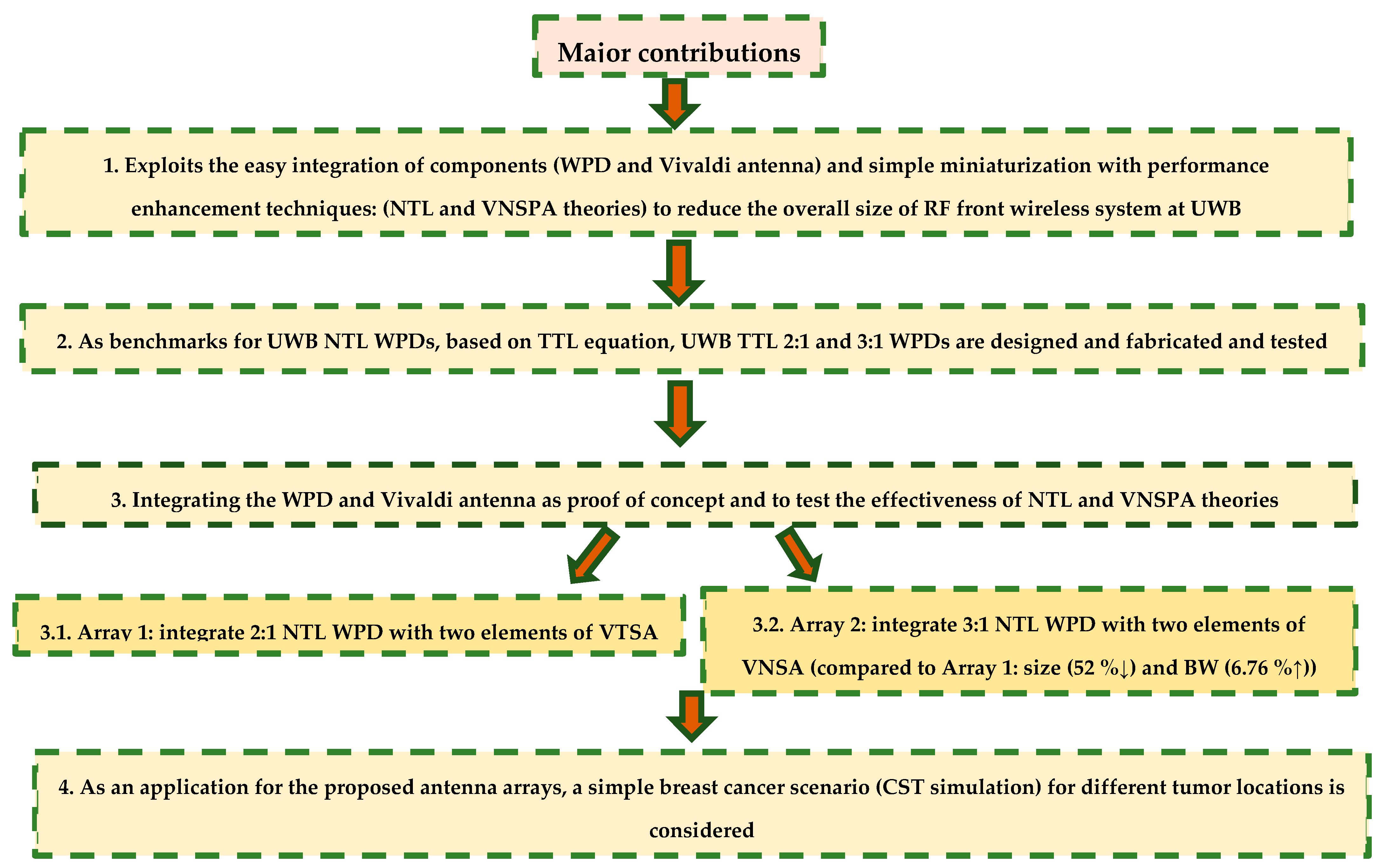
With the Internet of Things’ (IoT) rapid expansion and the connectivity of all devices, the primary concern in designing a modern wireless communication system is how to make it more reliable, compatible with recent application requirements, and suitable for customer needs. To that end, straightforward integration of equipment such as power dividers with antennas will aid in decreasing the overall size and power budget of the system. For this purpose, as a novelty of this work, at the UWB frequency band (3.1–10.6 GHz), the proposed compact UWB unequal split NTL WPD [27] is exploited as a feeding network for the compact UWB VTSA [1] and novel Vivaldi nonuniform slot antenna (VNSA) [28] to design, fabricate, and test simple compact Vivaldi arrays. Array 1 is achieved by integrating the designed compact UWB VTSA [1] and 2:1 unequal split NTL WPD [27]. Then, 52% compactness improvement with 6.76% BW enhancement is achieved in Array 2 by integrating the compact UWB VNSA and 3:1 unequal split WPD designed in [28] and [27], respectively. This work is regarded as proof of concept for the effectiveness of applying the NTL [27,29] and VNSPA [28] theories for compactness while maintaining or improving performance. Due to the good characteristics of the proposed arrays in terms of ease of integration, small size, wide BW, high gain, and stable directive radiation patterns, they are good candidates for breast cancer detection (BCD) applications. To prove that, a simple BCD scenario based on CST simulation is included in this work. The major contributions of this work are arranged in Figure 1 below.
2. The Proposed Antenna Design
2.1. Simple Compact 2 × 1 UWB Linear VTSA Array (Array 1)
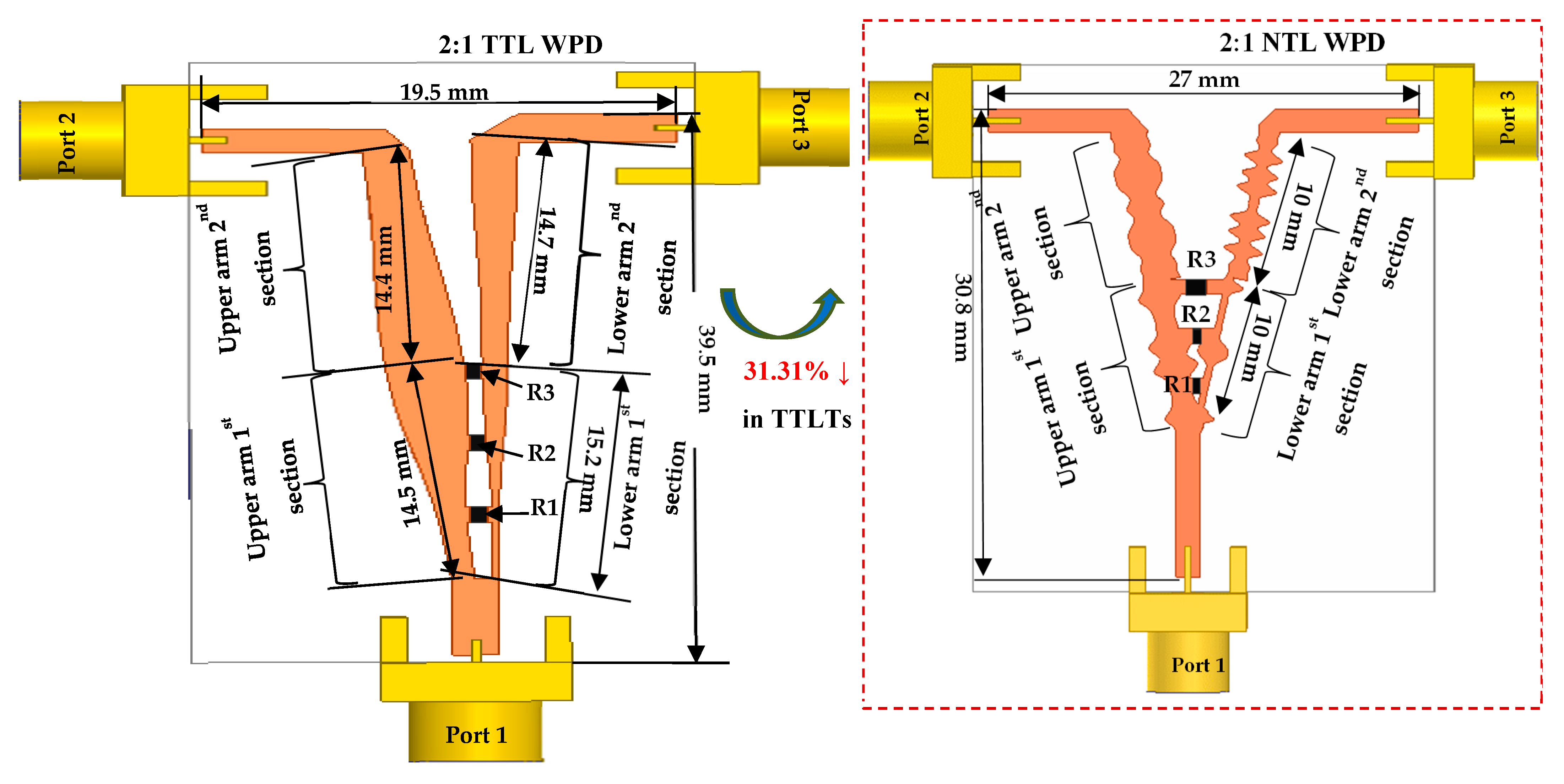
To design a compact and effective array for UWB applications, at 3.1–10.6 GHz, the compact 2:1 NTL WPD [27] is chosen in this work as a feeding network to the 2 × 1 VTSA array (Array 1). As a contribution and to demonstrate the performance of the NTL WPD despite the 33.31% compactness in its λ/4 transformers, the designed 2:1 UWB tapered transmission line (TTL) WPD based on the special TTL equation [30] is used here as a benchmark as shown in Figure 2. In this work, Rogers RO4003C substrate material (with a dielectric constant (εr) = 3.55, height (h) = 0.813 mm, dielectric loss tangent of 0.0027, and copper thickness = 0.035 mm) is chosen due to (1) its excellent performance at high frequencies (low dielectric loss tolerance and loss), (2) excellent dimension stability, and (3) stable electrical properties versus frequency. Figure 2 illustrates the 33.31% size reduction of 2:1 NTL transformers (NTLTs) as compared to TTL transformers (TTLTs). According to the design equations of WPD in [31], isolation between ports requires an isolation resistor. As shown in Figure 2, three isolation resistors, R1 = 82 Ω (TTL) and 130 Ω (NTL), R2 = 620 Ω (TTL) and 300 Ω (NTL), and R3 = 470 Ω (TTL) and 180 Ω (NTL) are used to guarantee high isolation between the output ports (Port 2 and Port 3). These optimum values are determined based on detailed parametric studies in [27,30] that examine the effect of different resistor values on the divider’s matching, transmission, and isolation. It should be noted that more resistors can enhance the isolation; however, only three are selected in this work to avoid the difficulties in soldering and integrating the surface mount resistors in the short distance between the two transformers (NTLTs or TTLTs). Detailed parametric studies of 2:1 TTL and NTL WPDs can be found in [30] and [27], respectively. The comparison between their results (the values of S11, S22, S33, S23, S12, S13, S12 group delay (GD), S13 GD, S12 phase and S13 phase) are demonstrated in Figure 3 and Figure 4 and Table 1.
Figure 3a–f show that both dividers satisfy good input, output matching, and isolation between output ports through the UWB frequency band where the measured insertion losses S12 and S13 are close to the theoretical values, −1.76 dB and −4.77 dB, respectively. To reduce the effect of fabrication errors [32], the SMA connector is considered in the simulation of these dividers. The disturbance in the measured results shown in Figure 3d–f, especially at high frequencies beyond 8 GHz, is due to the worse impedance mismatch and the increased insertion loss (conductor and dielectric losses) for the non-pure TEM transmission line at higher frequencies [31]. In addition, the difference between the simulation and measurement environments contributes to this disturbance. To ensure that the radio signal is transmitted successfully in UWB applications, GD should be flat through the UWB frequency band [33]. As demonstrated in Figure 4a,b, the proposed dividers give a nearly flat GD, with an increase in measured findings owing to manufacturing and measurement tolerances, as well as the difference between the simulation and measurement environments. Finally, it is observed from Figure 4c,d that there is a slight phase difference between the NTL and TTL WPDs because of their transformers’ different lengths. This slight phase difference and the acceptable values of return loss and isolation of NTL WPD indicate the effectiveness of applying NTL theory [27,29] for compactness and performance improvement (wide BW) without the need for additional components. This makes the NTL WPD an excellent option for an antenna feeder.
Now, the NTL UWB WPD (in the dashed box in Figure 2) [27] is integrated with two elements of compact UWB VTSAs [1] to obtain a compact 2 × 1 UWB linear VTSA array as demonstrated in Figure 5, where r, Wmin, Wmax, LT, Lqw (LT/4), radsl(LT/2), Wa, Wp (50 Ω), War, and Lar are the tapering rate, aperture opening, the aperture width, the taper slot length, the quarter wavelength of both microstrip and slot lines in microstrip to slot (M/S) transition, the radius of the slot, the antenna feed line width, the width of three ports of NTL WPD, the width, and the length of the proposed antenna array, respectively. As illustrated in Figure 5, the exponential tapering profile was obtained using ±Aerx where x is the position along LT and A = 0.5 × Wmin. Based on the design equations explained in [1], at the UWB frequency band (3.1–10.6 GHz) with fC = 6.85 GHz, the calculated LT and Wmax are selected to be 25 mm (>23.99 mm at fC = 6.58 GHz) and 22 mm (20.88 mm < Wmax < 23.07 mm), respectively. sp is the space between the two elements and can be calculated using
where c is the speed of light.
Parametric Studies
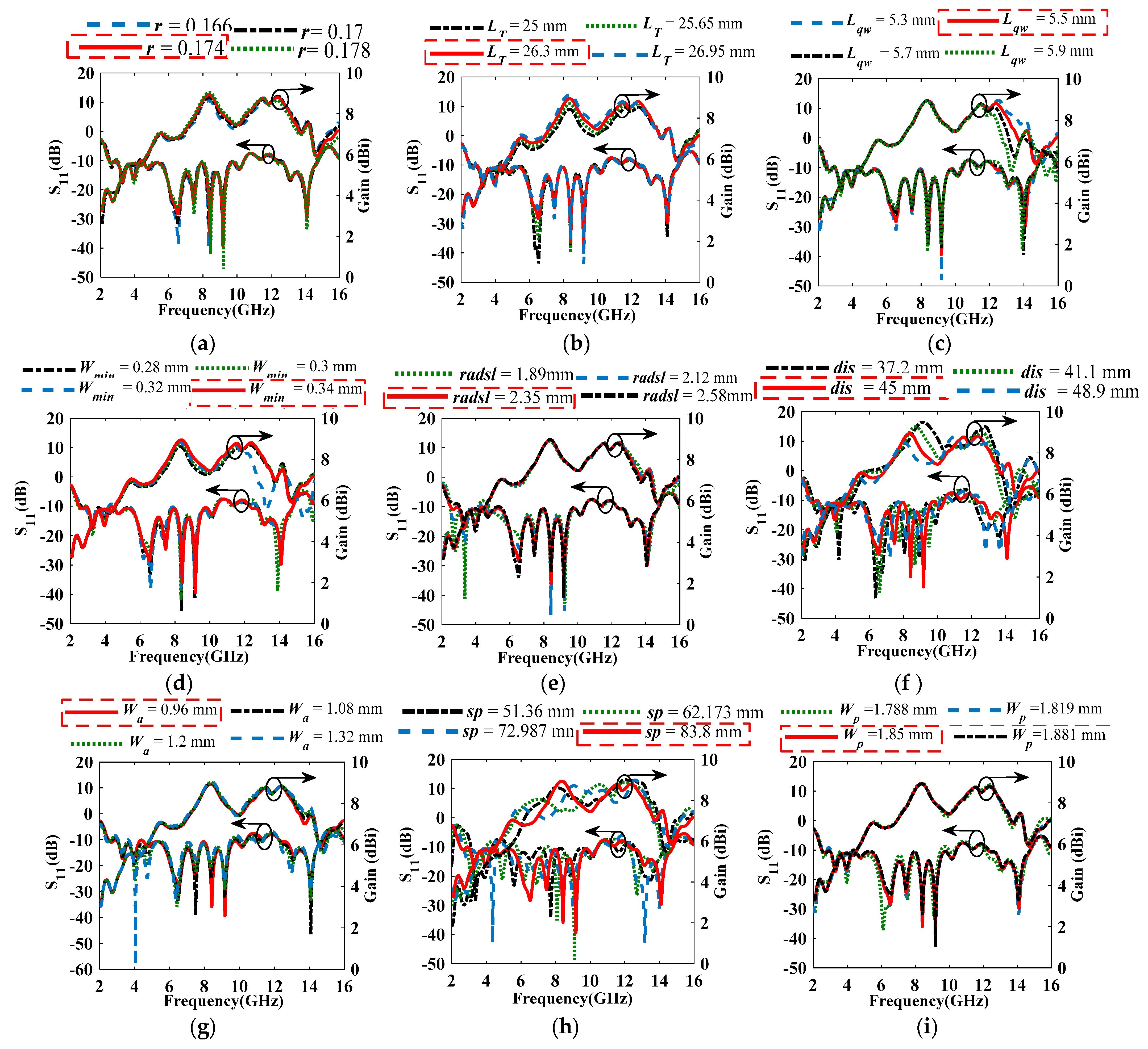
To address the array’s mismatch caused by the integration of the antenna and power divider, different parametric analyses are conducted as illustrated in Figure 6. The selected parameters are within the red dashed box. Figure 6a shows that the matching at r = 0.174 (S11 < −10.11 dB at 2.507–10.414 GHz and maximum gain (MG) = 8.94 dBi) is better than the optimized value for the single element, i.e., r = 0.17 (S11 < −9.69 dB) and at other values (r = 0.166 (S11 < −9.11 dB) and r = 0.178 (S11 < −9.6 dB). Figure 6b illustrates that the best obtained S11 is at LT = 26.3 mm (S11 < −10.11 dB at 2.507–10.414 GHz and MG = 8.94 dBi), which is better than at the optimized value for the single element, LT = 25 mm (S11 < −8.98 dB at 2.62–10.483 GHz MG = 8.4 dBi). Since r and LT in the array are higher than that of the single element, the value of Wmax is increased to 27.46 mm, which also will enhance the antenna gain [34].
As shown in Figure 6c, the best impedance matching is achieved at Lqw = 5.5 mm (S11 < −10.11 dB at 2.507–10.414 GHz and MG = 8.94 dBi), which is better than that at the optimized value for the single element, Lqw = 5.7 mm (S11 < −9.84 dB). As illustrated in Figure 6d, Wmin = 0.34 mm (S11 < −10.11 dB at 2.507–10.414 GHz and MG = 8.94 dBi) gives the best impedance matching and highest gain (related to Wmax), which is better than that at the optimized value for the single element, Wmin = 0.3 mm (S11 < −9.57 dB at 2.62–10.38 GHz and MG = 8.72 dBi). Figure 6e shows that as radsl increases, the BW decreases, and the gain increases. However, the best S11 is obtained at radsl = 2.35 mm (S11 < −10.11 dB at 2.507–10.414 GHz and MG = 8.94 dBi), which is better than that at the optimized value for the single element, i.e., at radsl = 1.89 mm (S11 < −7.96 dB). Although at radsl = 2.58 mm (S11 < −10 dB at 3.03–10.419 GHz and MG = 8.96 dBi), the gain is 0.78% higher, radsl = 2.35 mm is selected because of its improved impedance matching and broader BW. Since dis is related to the antenna width of a single element, Want = dis + Lqw, it affects the BW. As dis increases, the BW enhances as shown in Figure 6f. The best impedance matching is obtained at dis = 45 mm (S11 < −10.11 dB at 2.507–10.414 GHz and MG = 8.94 dBi), which is better than at the optimized value for the single element, dis = 37.2 mm (S11 < −8.85 dB).
The best impedance matching is found, as shown in Figure 6g at Wa = 0.96 mm (S11 < −10.11 dB at 2.507–10.414 GHz and MG = 8.94 dBi), which is better than at the optimized value for the single element, Wa = 1.2 mm (S11 < −8.81 dB). As shown in Figure 6h, the obtained impedance matching is not satisfactory at the calculated sp = 51.36 mm (S11 < −7.12 dB at 3.11–10.43 GHz and MG = 8.6 dBi); however, as sp increases (>51.36 mm), the impedance matching and gain improve, and the best matching is achieved at sp = 83.8 mm (S11 < −10.11 dB at 2.507–10.414 GHz and MG = 8.94 dBi). Finally, the optimum impedance matching level is reached, as seen in Figure 6i at WP = WP1 (for port 1) = WP2 (for port 2) = WP3 (for port 3) = 1.85 mm (S11 < −10.11 dB at 2.507–10.414 GHz and MG = 8.94 dBi), which outperforms the calculated one at WP = 1.819 mm (S11 < −9.16 dB). The optimized values for Array 1 with its single element (VTSA) are illustrated in Table 2.
2.2. Ultra Compact 2 × 1 UWB Linear VNSA Array (Array 2)
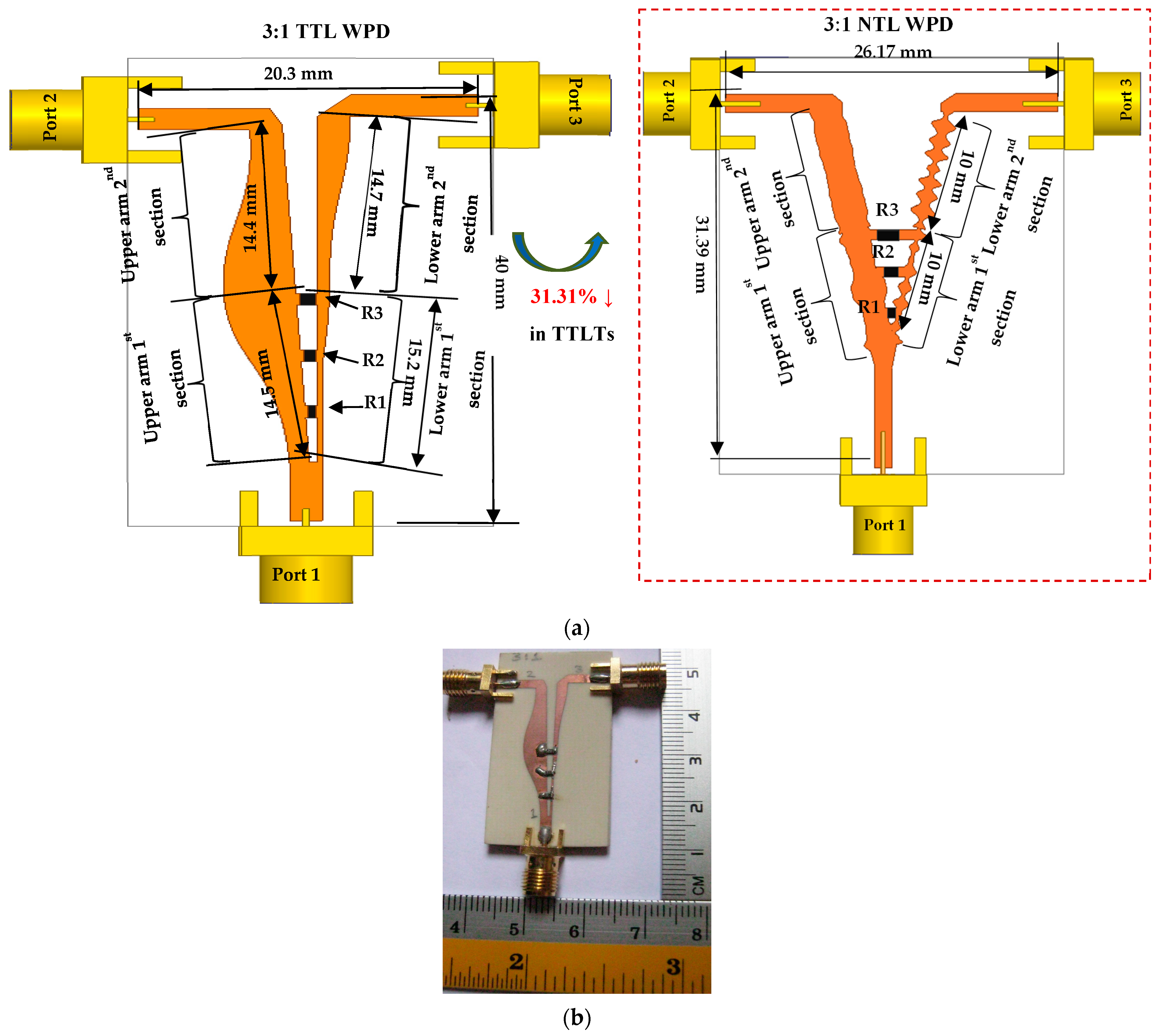
At the UWB frequency band (3.1–10.6 GHz), the compact UWB 3:1 NTL WPD [27] is selected here only to show its applicability as an antenna array’s feeding network. As a contribution and to test the 3:1 NTL WPD performance, a 3:1 TTL WPD is designed, fabricated, and tested using the same concept as in [30]. The 33.31% size reduction of 3:1 NTLTs as compared to TTLTs is shown in Figure 7a. The prototype of 3:1 TTL WPD is shown in Figure 7b. Based on the detailed parametric values on the effect of the isolation resistors on the divider performance, the R1, R2, and R3 values for 3:1 TTL WPD are 180 Ω, 910 Ω, and 240 Ω, respectively. However, they are equal to 270 Ω, 390 Ω, and 240 Ω, respectively, for 3:1 NTL WPD. The results of the two dividers are demonstrated in Table 3 and Figure 8 and Figure 9, which show the effectiveness of using NTL theory [27,29] to compact the 3:1 NTL WPD without degrading its performance. In terms of matching, isolation, and group delay, both dividers operate well over the UWB frequency spectrum. It can be observed that the measured insertion losses for both dividers, S12 and S13, are close to the theoretical values, −1.24 dB and −6 dB, respectively.
As a novelty in this work, the advantage of NTL [27,29] and VNSPA [28] theories is exploited to design the compact version of Array 1 by integrating two elements of the predesigned compact UWB VNSA [28] with 3:1 unequal split NTL WPD (in the dashed box of Figure 7) [27], resulting in the compact VNSA array (Array 2), as illustrated in Figure 10. Since the size of VNSA [28] is 51.94% smaller than VTSA [1], 52% compactness is achieved in the resulting array with a 6.76% BW enhancement and this illustrates the efficiency of applying the NTL and VNSPA theories to miniaturize the size of UWB WPD and VTSA, respectively, while maintaining good performance. The next section explains the parametric studies performed on Array 2 for performance enhancement.
Parametric Studies
As a result of the Vivaldi antenna’s ease of integration with other circuits, it provides good impedance matching of (S11 < −10.44 dB at 3.22–12.85 GHz and maximum gain of 8.4 dBi) with dimensions: radsl = 1.35 mm, dis = 21.8 mm, Wa = 1.34 mm, sp = 50 mm, Wp1 = 2.07 mm, and Wp2 = 1.7 mm, as shown in Figure 11. According to [28], it is worth mentioning here that the nonuniform slot length (LN) is 33.33% reduced from LT in [1] and r, Wmin, and Wmax cannot be changed here, as they are used in the constraints of the optimization MATLAB code to satisfy the equivalency between VTSA [1] and VNSA [28]. As illustrated in Figure 11a, 11b, and 11c, the impedance matching at radsl = 1.35 mm, dis = 21.8 mm, and sp = 50 mm are better than that at (radsl = 1.135 mm (S11 < −8.49 dB), 1.505 mm (S11 < −9.29 dB), and 1.69 mm (S11 < −8.51 dB)), (dis = 19.8 mm (S11 < −9.34 dB), 23.8 mm (S11 < −10.28 dB) 25.8 mm (S11 < −10.14 dB)), and (sp = 40 mm (S11 < −8.02 dB), 60 mm (S11 < −6.98 dB), and 70 mm (S11 < −7.66 dB)), respectively. Also here, the antenna feedline and divider port widths at the calculated value, Wa = 1.82 mm (S11 < −7.87 dB at 2.42–12.85 GHz and maximum gain of 8.4 dBi), Wp1 = 1.82 mm (S11 < −8.63 dB) and Wp2 = 1.82 mm (S11 < −9.74 dB) are not good as compared to the optimized ones, Wa = 1.34 mm, Wp1 = 2.07 mm and Wp2 = 1.7 mm in terms of impedance matching, as shown in Figure 11d, Figure 11e, and Figure 11f, respectively.
As compared to Array 1, the values of LT, dis, and sp are reduced from 26.3 mm to 16.75 mm, 45 mm to 21.8 mm, and 83.3 mm to 50 mm, respectively, which helps in reducing the size of Array 2 by more than 50% and enhancing the BW by 17.76% with only a 6.2% reduction in gain as compared to Array 1. The optimized values for Array 2 with its single element (VNSA) are illustrated in Table 4. The prototypes of the proposed arrays are shown in Figure 12.
3. Results and Discussion
Both arrays provide good measured and simulated results, as summarized in Table 5 and illustrated in Figure 13. Arrays 1 and 2 provide good, measured input impedance matching of <−10.28 dB (Sim. < −10.11 dB) and <−10.2 dB (Sim. < −10.29 dB) through 3.24–13 GHz (Sim. 3.22–12.85 GHz), respectively, as shown in Figure 13a, which implies the effectiveness of integrating the UWB VTSA [1] and VNSA [28] and UWB 2:1 and 3:1 unequal split NTL WPDs [27] for compactness and gain enhancement. As can be observed from Figure 13a and Table 5, with the 52% size reduction and 6.76% (Sim. 17.96%) BW improvement provided by Array 2, only 5.46% (Sim. 6.26%) of the MG is reduced. This implies the effectiveness of the VNSPA theory [28] for compactness and performance enhancement. Due to the difference in the signal path through the VTSA and VNSA in Array 1 and 2, respectively, there is a slight phase difference, as shown in Figure 13b. Fabrication tolerance, human and lab error, improper soldering of SMA connectors, and the difference between the simulation and actual measurement environment are the causes of the discrepancy between the results from the simulation and the findings from the measurements. It can be noticed from Table 5 and Figure 13c that the MG of the proposed Array 1 and 2 is enhanced by 23.39% (Sim. 25.84%) and 15.11% (Sim. 15.38%) as compared to the VTSA and VNSA single elements, respectively. Also, it can be noticed that the gain for Array 1 and Array 2 after reaching their peak values at around 8.8 GHz (Array 1: 8.61 dBi and Array 2: 8.1 dBi) reduces to 7.9 dBi and 7.8 dBi, respectively, at 9–10 GHz. These fluctuations mainly result from high-order modes at high frequency. Also, Figure 13d and Table 5 indicate that Arrays 1 and 2 achieve good efficiencies between 68.92% and 81.39% (Sim. 70.98% and 93.52%) and 73.17% and 92.11% (74.75% and 94.77%), respectively, at UWB. The good impedance matching of the proposed arrays can be expressed also in terms of the simulated input impedance, as shown in Figure 13d, where its real and imaginary parts oscillate around 50 Ω and 0 Ω, respectively.
A nearly flat group delay within the UWB frequency band is an important feature for UWB applications, to guarantee satisfaction of signal transmission. The measurement setup to obtain the face-to-face (F 2 F) group delay between two samples of Array 1 and Array 2 with R = 400 mm and 800 mm, respectively, are shown in Figure 14a. Figure 14b depicts that the approximate measured flat measured group delay provided by Arrays 1 and 2 are around 3.5 ns (Sim = 2.5 ns) and 2.3 ns (Sim = 1.7 ns). The measured group delay is greater than the simulated one due to the fabrication and measurement tolerance in which the signal will face more losses during its propagation.
The normalized simulated and measured radiation patterns of Array 1 and 2 are displayed in 2D polar plots and illustrated in Figure 15a–f at f = 5.85 GHz, 8.2 GHz, and 10.45 GHz for E-plane (XY-plane) and H-plane (XZ-plane). Due to higher-order modes and losses associated with fabrication errors and measurement tolerance, side lobe levels (SLLs) are introduced to patterns at high frequencies (8.2–10.45 GHz), which makes the measured pattern shape differ from the simulated one and it is more severe at the H-plane.
Finally, Table 6 illustrates other recent related work in the literature on different UWB VTSA arrays and DSVA. As illustrated in Table 5, Array 1 and Array 2 are the smallest, among others (for the 1 × N array, only the size of 1 × 2 is taken for comparison), and they provide wider BW than [5,9,11,12,18,20] and moderate high gain without any enhancement techniques. Although the size (1 × 2 case) of the VTSA arrays in [18,26] is smaller than Array 1 and Array 2, they provide higher gain and wider BW, respectively.
4. Application of The Proposed Antenna Design for Cancer Detection Scenario
Transmitting UWB signals to the breast (with and without tumor) and monitoring the backscattered S-parameters allow microwave imaging to detect the electrical differences between normal and malignant cells. Based on this approach, four samples of the proposed Array 2 are placed around a hemispherical breast phantom (radius = 50 mm) at a 10 mm distance in front of it. The phantom consists of skin, fat, and fibroglandular tissues including a tumor (diameter of 10 mm) deeply inside it, as shown in Figure 16a. Based on [35,36,37], the densities and electric properties of the breast phantom tissues, respectively, are illustrated in Table 7. As demonstrated in Figure 16a–e, the Robust Time Reverse (RTR) method [38] reconstructs the tumor’s 2D images from the antennas’ reflected and scattered signals with various considerations such as a smaller tumor, an off-center tumor, and more than one tumor (two and three). The features of the suggested antenna and the reconstructed images in Figure 16a–e demonstrate the antenna’s capacity to detect any tumor at any location inside the breast.
Finally, to guarantee the safety of the body from harmful electromagnetic radiation, the specific absorption rate (SAR) distribution of Array 2 (four samples) within the breast phantom, including the tumor, is calculated for an input power of 0.1 W at different resonance frequencies. The results are illustrated in Figure 17 where they do not exceed the safety limit and are less than the limit recommended by the council of the European Union (2 W/kg averaged over 10 g of actual tissue).
5. Conclusions
As proof of concept in the application of the NTL and VNSPA theories for compactness, while maintaining or enhancing good performance, the novelty of this work is achieved by designing, fabricating, and testing simple 2 × 1 linear compact VTSA and VNSA arrays at UWB frequency band (3.1–10.6 GHz). The compact VTSA array (Array 1) and VNSA array (Array 2) outperform the VTSA and VNSA single components in terms of enhanced impedance and gain by 24.39% and 15.11%, respectively. Array 2 achieves 52% compactness with 6.76% BW enhancement as compared to Array 1. The suggested compact arrays with high gain, wideband, stable radiation patterns, and low SAR are good candidates for high-resolution medical applications such as breast cancer detection (BCD), which is addressed in this paper using Array 2 based on the CST simulator. Detailed simulation and measurement setups for breast and brain cancer detection using N × 1 VTSA or VNSA arrays are aimed to be considered in our future work.
Author Contributions
Conceptualization, S.S.; validation, S.S.; formal analysis, S.S.; investigation, S.S.; resources, S.S.; data curation, S.S. and T.S.; writing—original draft preparation, S.S.; writing—review and editing, S.S., T.S. and N.T.; visualization, S.S., T.S. and N.T.; supervision, T.S. and N.T.; project administration, N.T.; funding acquisition, N.T. All authors have read and agreed to the published version of the manuscript.
Funding
This work was supported by Enterprise Ireland, Ireland.
Data Availability Statement
Data are contained within the article.
Conflicts of Interest
The authors declare no conflicts of interest.
References
- Saleh, S.; Ismail, W.; Abidin, I.S.Z.; Jamaluddin, M.H.; Bataineh, M.H.; Alzoubi, A.S. Compact UWB Vivaldi Tapered Slot Antenna. Alex. Eng. J. 2022, 61, 4977–4994. [Google Scholar] [CrossRef]
- Balanis, C.A. Antenna Theory: Analysis and Design; John Wiley & Sons: Hoboken, NJ, USA, 2016; ISBN 1118642066. [Google Scholar]
- Roshani, S.; Roshani, S.; Zarinitabar, A. A Modified Wilkinson Power Divider with Ultra Harmonic Suppression Using Open Stubs and Lowpass Filters. Analog. Integr. Circuits Signal Process. 2019, 98, 395–399. [Google Scholar] [CrossRef]
- Al Shamaileh, K.; Dib, N.; Abushamleh, S. A Dual-Band 1: 10 Wilkinson Power Divider Based on Multi-T-Section Characterization of High-Impedance Transmission Lines. IEEE Microw. Wirel. Compon. Lett. 2017, 27, 897–899. [Google Scholar] [CrossRef]
- Liu, Y.Q.; Liang, J.G.; Wang, Y.W. Gain-Improved Double-Slot TSA with Y-Shaped Corrugated Edges. Electron. Lett. 2017, 53, 759–760. [Google Scholar] [CrossRef]
- Wang, Y.-W.; Wang, G.-M.; Zong, B.-F. Directivity Improvement of Vivaldi Antenna Using Double-Slot Structure. IEEE Antennas Wirel. Propag. Lett. 2013, 12, 1380–1383. [Google Scholar] [CrossRef]
- Wang, Y.-W.; Wang, G.-M.; Yu, Z.-W.; Liang, J.-G.; Gao, X.-J. Ultra-Wideband E-Plane Monopulse Antenna Using Vivaldi Antenna. IEEE Trans. Antennas Propag. 2014, 62, 4961–4969. [Google Scholar] [CrossRef]
- Mohammad, Z.; Sarker, N.; Das, C. Design and Analysis of a Double Slotted with Multiple Strips Vivaldi Antenna for High-Speed 5G Communications. In Proceedings of the 3rd IEEE International Conference on Telecommunications and Photonics, ICTP 2019, Dhaka, Bangladesh, 28–30 December 2019; pp. 19–22. [Google Scholar] [CrossRef]
- Kumar, P.; Akhter, Z.; Jha, A.K.; Akhta, M.J. Directivity Enhancement of Double Slot Vivaldi Antenna Using Ani Isotropic Zero-Index Me Etamaterials. In Proceedings of the 2015 IEEE International Symposium on Antennas and Propagation & USNC/URSI National Radio Science Meeting, Vancouver, BC, Canada, 19–24 July 2015; pp. 2333–2334. [Google Scholar]
- Hoang, M.-H.; Yang, K.; John, M.; McEvoy, P.; Ammann, M. Ka-Band Vivaldi Antenna with Novel Core Element for High-Gain. In Proceedings of the Loughborough Antennas & Propagation Conference (LAPC 2017), Loughborough, UK, 13–14 November 2017; IET: London, UK, 2017; pp. 1–4. [Google Scholar]
- Zhu, S.; Liu, H.; Wen, P.; Du, L.; Zhou, J. A Miniaturized and High Gain Double-Slot Vivaldi Antenna Using Wideband Index-Near-Zero Metasurface. IEEE Access 2018, 6, 72015–72024. [Google Scholar] [CrossRef]
- Witriani, F.N.; Amrullah, Y.S.; Darwis, F.; Taufiqqurrachman, T.; Wijayanto, Y.N.; Paramayudha, K.; Elisma, E. Gain Enhancement of Double-Slot Vivaldi Antenna Using Corrugated Edges and Semicircle Director for Microwave Imaging Application. J. Elektron. Dan Telekomun. 2021, 21, 85. [Google Scholar] [CrossRef]
- Khaled Ahmed, S.; Abdul Hassain, Z.A. Design of High Gain Antenna Based on Array of Double Slot Vivaldi Structure. J. Eng. Sustain. Dev. 2020, 24, 241–246. [Google Scholar] [CrossRef]
- Lin, S.; Yang, S.; Fathy, A.E.; Elsherbini, A. Development of a Novel UWB Vivaldi Antenna Array Using SIW Technology. Prog. Electromagn. Res. 2009, 90, 369–384. [Google Scholar] [CrossRef]
- Yao, Y.; Liu, M.; Chen, W.; Feng, Z. Analysis and Design of Wideband Widescan Planar Tapered Slot Antenna Array. IET Microw. Antennas Propag. 2010, 4, 1632–1638. [Google Scholar] [CrossRef]
- Soothar, P.; Wang, H.; Muneer, B.; Dayo, Z.A.; Chowdhry, B.S. A Broadband High Gain Tapered Slot Antenna for Underwater Communication in Microwave Band. Wirel. Pers. Commun. 2021, 116, 1025–1042. [Google Scholar] [CrossRef]
- Ren, J.; Fan, H.; Tang, Q.; Yu, Z.; Xiao, Y.; Zhou, X. An Ultra-Wideband Vivaldi Antenna System for Long-Distance Electromagnetic Detection. Appl. Sci. 2022, 12, 528. [Google Scholar] [CrossRef]
- Ghimire, J.; Diba, F.D.; Kim, J.H.; Choi, D.Y. Vivaldi Antenna Arrays Feed by Frequency-Independent Phase Shifter for High Directivity and Gain Used in Microwave Sensing and Communication Applications. Sensors 2021, 21, 6091. [Google Scholar] [CrossRef] [PubMed]
- Li, P.; Liang, J.; Chen, X.; Parini, C. A 4-Element Ultra-Wideband Tapered-Slot-Fed Antenna Array. In Proceedings of the 2006 IEEE Antennas and Propagation Society International Symposium, Albuquerque, NM, USA, 9–14 July 2006; pp. 4475–4478. [Google Scholar]
- Xiao, B.; Yao, H.; Li, M.; Hong, J.S.; Yeung, K.L. Flexible Wideband Microstrip-Slotline-Microstrip Power Divider and Its Application to Antenna Array. IEEE Access 2019, 7, 143973–143979. [Google Scholar] [CrossRef]
- Tianang, E.G.; Elmansouri, M.A.; Filipovic, D.S. Cavity-Backed Vivaldi Array Antenna. In Proceedings of the 2016 10th European Conference on Antennas and Propagation, EuCAP 2016, Davos, Switzerland, 10–15 April 2016; Volume 1, pp. 1–4. [Google Scholar] [CrossRef]
- Tianang, E.G.; Elmansouri, M.A.; Filipovic, D.S. Flush-Mountable Vivaldi Array Antenna. In Proceedings of the 2016 IEEE Antennas and Propagation Society International Symposium, APSURSI 2016—Proceedings, Fajardo, PR, USA, 26 June–1 July 2016; Volume 425, pp. 1837–1838. [Google Scholar] [CrossRef]
- Tianang, E.G.; Member, S.; Elmansouri, M.A.; Member, S.; Filipovic, D.S.; Member, S.; An, A. Ultra-Wideband Lossless Cavity-Backed Vivaldi Antenna. IEEE Trans. Antennas Propag. 2018, 66, 115–124. [Google Scholar] [CrossRef]
- Prakash, A.; Chattoraj, N.; Shukla, S.B. Design and Development of Vivaldi Antenna Array for Wind Profiler RADAR Application. Microw. Opt. Technol. Lett. 2018, 60, 725–731. [Google Scholar] [CrossRef]
- Dong, Y.; Choi, J.; Itoh, T. Vivaldi Antenna with Pattern Diversity for 0.7 to 2.7 GHz Cellular Band Applications. IEEE Antennas Wirel. Propag. Lett. 2018, 17, 247–250. [Google Scholar] [CrossRef]
- Liu, H.; Liu, Y.; Zhang, W.; Gao, S. An Ultra-Wideband Horizontally Polarized Omnidirectional Circular Connected Vivaldi Antenna Array. IEEE Trans. Antennas Propag. 2017, 65, 4351–4356. [Google Scholar] [CrossRef]
- Saleh, S.; Ismail, W.; Zainal Abidin, I.S.; Jamaluddin, M.H.; Al-Gailani, S.A.; Alzoubi, A.S.; Bataineh, M.H. Nonuniform Compact Ultra-Wide Band Wilkinson Power Divider with Different Unequal Split Ratios. J. Electromagn. Waves Appl. 2020, 34, 154–167. [Google Scholar] [CrossRef]
- Saleh, S.; Ismail, W.; Zainal Abidin, I.S.; Jamaluddin, M.H.; Bataineh, M.H.; Al-Zoubi, A.S. Novel Compact UWB Vivaldi Nonuniform Slot Antenna with Enhanced Bandwidth. IEEE Trans. Antennas Propag. 2022, 70, 6592–6603. [Google Scholar] [CrossRef]
- Saleh, S.; Timmons, N.; Morrison, J.; Ismail, W. Compact Linearly Polarized 5G Vivaldi Non-Uniform Slot Filtering Antenna. Ain Shams Eng. J. 2023, 15, 102364. [Google Scholar] [CrossRef]
- Saleh, S.; Ismail, W.; Zainal Abidin, I.S.; Jamaluddin, M.H.; Bataineh, M.H.; Alzoubi, A.S. N-Way Compact Ultra-Wide Band Equal and Unequal Split Tapered Transmission Lines Wilkinson Power Divider. Jordanian J. Comput. Inf. Technol. 2020, 6, 291–302. [Google Scholar] [CrossRef]
- Pozar, D.M. Microwave Engineering; John Wiley & Sons: Hoboken, NJ, USA, 2011; ISBN 0470631554. [Google Scholar]
- Parveen, F.; Wahid, P. Design of Miniaturized Antipodal Vivaldi Antennas for Wideband Microwave Imaging of the Head. Electronics 2022, 11, 2258. [Google Scholar] [CrossRef]
- Elsheakh, D.M.N.; Eltresy, N.A.; Abdallah, E.A. Ultra Wide Bandwidth High Gain Vivaldi Antenna for Wireless Communications. Prog. Electromagn. Res. 2017, 69, 105–111. [Google Scholar] [CrossRef]
- Gibson, P.J. The Vivaldi Aerial. In Proceedings of the 1979 9th European Microwave Conference, Brighton, UK, 17–20 September 1979; IEEE: New York, NY, USA, 1979; pp. 101–105. [Google Scholar]
- AlFares, B.; AlJabr, A.; Zainalabedin, M.; AlMuzain, M.; Saleh, G.; AlHashim, M. Heterogenous Breast Phantom with Carcinoma for Ionizing Machines. In Proceedings of the 2021 IEEE International IOT, Electronics and Mechatronics Conference (IEMTRONICS), Toronto, ON, Canada, 21–24 April 2021; IEEE: New York, NY, USA, 2021; pp. 1–6. [Google Scholar]
- White, S.A.; Landry, G.; Van Gils, F.; Verhaegen, F.; Reniers, B. Influence of Trace Elements in Human Tissue in Low-Energy Photon Brachytherapy Dosimetry. Phys. Med. Biol. 2012, 57, 3585–3596. [Google Scholar] [CrossRef] [PubMed]
- Ruvio, G.; Solimene, R.; Cuccaro, A.; Fiaschetti, G.; Fagan, A.J.; Cournane, S.; Cooke, J.; Ammann, M.J.; Tobon, J.; Browne, J.E. Multimodal Breast Phantoms for Microwave, Ultrasound, Mammography, Magnetic Resonance and Computed Tomography Imaging. Sensors 2020, 20, 2400. [Google Scholar] [CrossRef]
- Saeidi, T.; Ismail, I.; Mahmood, S.N.; Alani, S.; Alhawari, A.R.H. Microwave Imaging of Voids in Oil Palm Trunk Applying UWB Antenna and Robust Time-Reversal Algorithm. J. Sens. 2020, 2020, 8895737. [Google Scholar] [CrossRef]
Figure 1.
The major contributions in this work.

Figure 2.
Configuration of compact UWB 2:1 unequal split TTL and NTL WPDs.

Figure 3.
Measured and simulated (a) S11, (b) S22, (c) S33, (d) S12, (e) S13, (f) S23 of compact UWB 2:1 NTL and TTL WPDs.
Figure 3.
Measured and simulated (a) S11, (b) S22, (c) S33, (d) S12, (e) S13, (f) S23 of compact UWB 2:1 NTL and TTL WPDs.

Figure 4.
Measured and simulated (a) S12 GD, (b) S13 GD, (c) S12 phase, and (d) S13 phase of compact UWB 2:1 NTL and TTL WPDs.
Figure 4.
Measured and simulated (a) S12 GD, (b) S13 GD, (c) S12 phase, and (d) S13 phase of compact UWB 2:1 NTL and TTL WPDs.

Figure 5.
Layout of Array 1.

Figure 6.
Parametric study of the proposed UWB Array 1 in terms of S11 and gain on (a) r, (b) LT, (c) Lqw, (d) Wmin, (e) radsl, (f) dis, (g) Wa, (h) sp, and (i) Wp.
Figure 6.
Parametric study of the proposed UWB Array 1 in terms of S11 and gain on (a) r, (b) LT, (c) Lqw, (d) Wmin, (e) radsl, (f) dis, (g) Wa, (h) sp, and (i) Wp.

Figure 7.
(a) Configuration of compact UWB 3:1 unequal split TTL and NTL WPDs and (b) prototype of 3:1 TTL WPD.
Figure 7.
(a) Configuration of compact UWB 3:1 unequal split TTL and NTL WPDs and (b) prototype of 3:1 TTL WPD.

Figure 8.
Measured and simulated (a) S11, (b) S22, (c) S33, (d) S12, (e) S13, (f) S23 of compact UWB 3:1 NTL and TTL WPDs.
Figure 8.
Measured and simulated (a) S11, (b) S22, (c) S33, (d) S12, (e) S13, (f) S23 of compact UWB 3:1 NTL and TTL WPDs.

Figure 9.
Measured and simulated (a) S12 GD, (b) S13 GD, (c) S12 phase, and (d) S13 phase of compact UWB 3:1 NTL and TTL WPDs.
Figure 9.
Measured and simulated (a) S12 GD, (b) S13 GD, (c) S12 phase, and (d) S13 phase of compact UWB 3:1 NTL and TTL WPDs.

Figure 10.
Layout of Array 2.

Figure 11.
Parametric study of the proposed UWB Array 2 in terms of S11 and gain on (a) radsl, (b) dis, (c) sp, (d) Wa, (e) Wp1, and (f) Wp2.
Figure 11.
Parametric study of the proposed UWB Array 2 in terms of S11 and gain on (a) radsl, (b) dis, (c) sp, (d) Wa, (e) Wp1, and (f) Wp2.

Figure 12.
Photograph of the fabricated arrays: (a) front view and (b) back view.

Figure 13.
Simulated and measured (a) S11, (b) phase, (c) gain, and (d) simulated input impedance of the proposed arrays.
Figure 13.
Simulated and measured (a) S11, (b) phase, (c) gain, and (d) simulated input impedance of the proposed arrays.

Figure 14.
(a) Measurement setup and (b) simulated and measured group delay of the proposed arrays.

Figure 15.
Simulated (dashed) and measured (solid) radiation patterns of the proposed compact UWB Vivaldi tapered and nonuniform arrays at f = 5.85 GHz (a) E and (b) H; f = 8.2 GHz (c) E and (d) H and f = 10.45 GHz (e) E and (f) H.
Figure 15.
Simulated (dashed) and measured (solid) radiation patterns of the proposed compact UWB Vivaldi tapered and nonuniform arrays at f = 5.85 GHz (a) E and (b) H; f = 8.2 GHz (c) E and (d) H and f = 10.45 GHz (e) E and (f) H.

Figure 16.
Simulation setup of simple BCD using Array 2 (four samples) and reconstructed 2D image using RTR algorithm of (a) one breast tumor at the center, (b) one smaller breast tumor at the center, (c) one breast tumor off the center, (d) two breast tumors off the center, and (e) three breast tumors off the center.

Figure 17.
Simulated 3D SAR results over 10 g of the four elements of the proposed compact UWB Array 2 at (a) 3.35 GHz, (b) 4.35 GHz, (c) 8.86 GHz, (d) 12.72 GHz, and (e) 14.61 GHz.
Figure 17.
Simulated 3D SAR results over 10 g of the four elements of the proposed compact UWB Array 2 at (a) 3.35 GHz, (b) 4.35 GHz, (c) 8.86 GHz, (d) 12.72 GHz, and (e) 14.61 GHz.


Table 1.
The simulated (Sim.) and measured (Meas.) results for UWB 2:1 unequal split TTL and NTL WPDs.
Table 1.
The simulated (Sim.) and measured (Meas.) results for UWB 2:1 unequal split TTL and NTL WPDs.
| Parameters | Sim. | Meas. | ||
|---|---|---|---|---|
| NTL | TTL | NTL | TTL | |
| S11 | <−10.62 dB at 3.46 to over 12 GHz | <−11.84 dB at 1.4 to over 12 GHz | <−13.6 dB at below 1 to 10.34 GHz | <−10.55 dB at 2.27 to over 12 GHz |
| S22 | <−10.6 dB at below 1 to over 12 GHz | <−11 dB at below 1 to over 12 GHz | <−11.5 dB at below 1 to over 12 GHz | <−11.8 dB at 2.5 to 11.56 GHz |
| S33 | <−14 dB at 2.21 to over 12 GHz | <−11.15 dB at 2.88 to over 12 GHz | <−14.26 dB at 1.96 to over 12 GHz | <−11.26 dB at 2.63 to over 12 GHz |
| S23 | <−16.28 dB at 3.66 to over 12 GHz | <−14.17 dB at 1.7 to over 12 GHz | <−10 dB at 3.22 to over 12 GHz | <−13.71 dB at 2.45 to over 12 GHz |
| S12 | −1.76–1 dB | −1.76–1.5 dB | −1.76–1 dB | −1.76–1.5 dB |
| S13 | −4.77 ± 0.3 dB | −4.77 ± 0.3 dB | −4.77 ± 0.3 dB | −4.77 ± 0.3 dB |
| S12 GD | around 0.22 ns | around 0.25 ns | around 0.5 ns | around 0.45 ns |
| S13 GD | around 0.25 ns | around 0.25 ns | around 0.45 ns | around 0.45 ns |
“<”: less than.
Table 2.
Calculated and optimized parameters of Array 1 with its single element (VTSA).
| Parameters | Calculated | Optimized (VTSA [1]) | Optimized (Array 1) |
|---|---|---|---|
| r | - | 0.17 | 0.174 |
| Wmax (mm) | 24.45 | 21.03 | 27.46 |
| LT (mm) | 27 | 25 | 26.3 |
| Lqw (mm) | 6.57 | 5.7 | 5.5 |
| Wmin (mm) | - | 0.3 | 0.34 |
| radsl (mm) | 3.285 | 1.89 | 2.35 |
| Dis (mm) | - | 37.2 | 45 |
| sp | 52.36 | - | 83.3 |
| Wa (mm) | 1.819 | 1.2 | 0.96 |
| Wp1 (mm) | 1.819 | - | 1.85 |
| Wp2 = Wp3 (mm) | 1.819 | - | 1.85 |
| Lar (mm) | - | - | 56 |
| War (mm) | - | - | 135 |
Table 3.
The simulated (Sim.) and measured (Meas.) results for UWB 3:1 unequal split TTL and NTL WPDs.
Table 3.
The simulated (Sim.) and measured (Meas.) results for UWB 3:1 unequal split TTL and NTL WPDs.
| Parameters | Sim. | Meas. | ||
|---|---|---|---|---|
| NTL | TTL | NTL | TTL | |
| S11 | <−10 dB at 2.2 to over 12 GHz | <−11.23 dB at 2.1 to over 12 GHz | <−13.4 dB at 1.96 to 11.1 GHz | <−10.6 dB at 2.46 to over 12 GHz |
| S22 | <−10 dB at below 1 to 11.3 GHz | <−10.34 dB at below 1 to over 12 GHz | <−11.53 dB at below 1 to 12 GHz | <−10 dB at 3 to over 12 GHz |
| S33 | <−10.4 dB at 3.4 to over 10.25 GHz | <−11.91 dB at 2.91 to over 12 GHz | <−10 dB at 3 to over 12 GHz | <−10.35 dB at 3.48 to over 12 GHz |
| S23 | <−11.38 dB at 3.3 to over 12 GHz | <−14.49 dB at 1.74 to over GHz | <−12.15 dB at 2.8 to over 12 GHz | <−14.3 dB at 1.88 to over 12 GHz |
| S12 | −1.24–1.15 dB | −1.24–1.15 dB | −1.24–1.15 dB | −1.24–2 dB |
| S13 | −6 ± 0.7 dB | −6 ± 0.7 dB | −6 ± 0.7 dB | −6 ± 0.7 dB |
| S12 GD | around 0.23 ns | around 0.25 ns | around 0.43 ns | around 0.5 ns |
| S13 GD | around 0.25 ns | around 0.25 ns | around 0.45 ns | around 0.5 ns |
“<”: less than.
Table 4.
Calculated and optimized parameters of Array 2 with its single element (VNSA).
| Parameters | Calculated | Optimized (VNSA [28]) | Optimized (Array 2) |
|---|---|---|---|
| r | - | 0.17 | |
| Wmax (mm) | 24.45 | 21.03 | |
| LT (mm) | 27 | LN (mm) = 16.75 | |
| Lqw (mm) | 6.57 | 5.76 | 5.74 |
| Wmin (mm) | - | 0.286 | |
| radsl (mm) | 3.285 | 1.505 | 1.32 |
| dis (mm) | - | 23.8 | 21.8 |
| sp | 52.36 | - | 50 |
| Wa (mm) | 1.819 | 1.25 | 1.34 |
| Wp1 (mm) | 1.819 | - | 2.07 |
| Wp2 = Wp3 (mm) | 1.819 | - | 1.7 |
| Lar (mm) | - | - | 44.755 |
| War (mm) | - | - | 81.08 |
Table 5.
Simulated and measured results of UWB Array 1 and 2 as compared to single elements: UWB VTSA and VNSA.
Table 5.
Simulated and measured results of UWB Array 1 and 2 as compared to single elements: UWB VTSA and VNSA.
| Antenna, Area (mm2) | S11(dB), Frequency Band (GHz), BW (GHz) | Peak Realized Gain (dBi) % Improvement | Total Efficiency (%) Range | |||
|---|---|---|---|---|---|---|
| Meas. | Sim | Meas. | Sim | Meas. | Sim. | |
| VTSA | <−11.15, 3.14−13.48, 10.34 | <−10.84, 2.95–12.71, 9.76 | 2.2–6.51 | 2.1–6.63 | 83.72–91.93 | 84.7–96.1 |
| Array 1, 7560 mm2 | <−10.28, 2.42–11.52, 9.1 | <−10.11, 2.51–10.41, 7.9 | 3.36–8.61 (VTSA: 24.39%↑) | 3.49–8.94 (VTSA: 25.84%↑) | 68.92–81.39 | 70.98–93.52 |
| VNSA | <−10.89, 2.9–13.55, 10.65 | <−10.32, 2.34–12.88, 10.54 | 1.8–6.91 | 2.16–7.1 | 81.14–91.98 | 87.5–97.3 |
| Array 2, 3628.33 mm2 (52%↓) | <−10.2,3.24–13, 9.76 (Array1: 6.76%↑) | <−10.29, 3.22–12.85, 9.63 (Array1: 17.96%↑) | 2.51–8.14 (Array1: 5.46%↓, VNSA: 15.11%↑) | 2.83–8.39 (Array1: 6.26%↓, VNSA: 15.38%↑) | 73.17–92.11 | 74.75–94.77 |
Table 6.
Other related VTSA arrays and DSVA at different wide and ultra-wide frequency bands in the literature.
Table 6.
Other related VTSA arrays and DSVA at different wide and ultra-wide frequency bands in the literature.
| Ref. | εr | S11 (dB) at Freq Band (GHz), BW (GHz) | Gain (dBi) | Antenna, Feeding | Volume mm × mm, mm |
|---|---|---|---|---|---|
| Array 1 | 3.55 | <−10.28, 2.42–11.52, 9.1 | 3.36–8.61 | 1 × 2 VTSA array, NTL WPD | 135 × 56 × 0.813 |
| Array 2 | <−10.2, 3.24–13, 9.76 | 2.51–8.14 | 1 × 2 VNSA array, NTL WPD | 88.08 × 44.755 × 0.813 | |
| [7] | 2.65 | <−11.55, 2.25–11.1, 8.85 | 10.1–14.81 | (2 layers) DSVA with diagonal rectangular-shaped corrugations | 150 × 100 × 0.5 |
| [9] | 4.3 | <−12.7, 4->10, 6 | Directivity (3.96–12.54) | DSVA with loaded ZIM unit cells | 90 × 85 × 1 |
| [26] | 2.55 | <−10, 1.28–11.51, 10.23 | 0.5–4 | 1 × 16 VTSA array circularly connected, T-junction PD | × 1 |
| [11] | 2.65 | <−10, 2.4–12, 9.6 | 0.7–14.2 | DSVA with ZIM unit cells and pair of DGS | 130 × 80 × 1 |
| [20] | 10.2 | <−10, 3.4–8.3, 4.9 <−8.4, at 4.6 | 6.25–12.3 | H-plane 1 × 4 VTSA, MSM PD | NA |
| [12] | 3.55 | <−9.84, 4.2–11, 6.8 | 8–13.3 (Sim) | DSVA with director and corrugated slots | 130 × 80 × 0.813 |
| [18] | 4.3 | <−10, 2.5–6.8, 4.3 & 7.5–9.5, 2 | 6.5–14.12 | 1 × 6 VTSA array, T-junction PD | 167.48 × 158.25 × 0.6 |
VTSA: Vivaldi tapered slot antenna, VNSA: Vivaldi nonuniform slot antenna, NTL: nonuniform transmission line, WPD: Wilkinson power divider, ZIM: zero-index metamaterial, DSVA: double-slot Vivaldi antenna, MSM: Microstrip–Slotline–Microstrip and DGS: defected ground slot.
Table 7.
Densities and electric properties of the breast phantom tissues.
| Parameters | Skin | Fat | Fibroglandular | Tumor |
|---|---|---|---|---|
| Mass density (Kg/m3) | 1090 | 950 | 1000 | 440 |
| εr | 34.2 | 4.32 | 39.65 | 54.9 |
| Conductivity (S/m) | 4.67 | 0.509 | 7.65 | 4 |
Disclaimer/Publisher’s Note: The statements, opinions and data contained in all publications are solely those of the individual author(s) and contributor(s) and not of MDPI and/or the editor(s). MDPI and/or the editor(s) disclaim responsibility for any injury to people or property resulting from any ideas, methods, instructions or products referred to in the content. |
© 2024 by the authors. Licensee MDPI, Basel, Switzerland. This article is an open access article distributed under the terms and conditions of the Creative Commons Attribution (CC BY) license (https://creativecommons.org/licenses/by/4.0/).
Share and Cite
MDPI and ACS Style
Saleh, S.; Saeidi, T.; Timmons, N. Simple Compact UWB Vivaldi Antenna Arrays for Breast Cancer Detection. Telecom 2024, 5, 312-332. https://0-doi-org.brum.beds.ac.uk/10.3390/telecom5020016
AMA Style
Saleh S, Saeidi T, Timmons N. Simple Compact UWB Vivaldi Antenna Arrays for Breast Cancer Detection. Telecom. 2024; 5(2):312-332. https://0-doi-org.brum.beds.ac.uk/10.3390/telecom5020016
Chicago/Turabian StyleSaleh, Sahar, Tale Saeidi, and Nick Timmons. 2024. "Simple Compact UWB Vivaldi Antenna Arrays for Breast Cancer Detection" Telecom 5, no. 2: 312-332. https://0-doi-org.brum.beds.ac.uk/10.3390/telecom5020016