Article

Quantitative Contribution of Timber Ring Beams in the Dynamic Response of Adobe Masonry Structures

by
Georgios Xekalakis
1,
Petros Christou
1,2,*,
Dimitris Pitilakis
3 and
Nicholas Kyriakides
4
1
Frederick Research Center, Nicosia 1036, Cyprus
2
Department of Civil Engineering, Frederick University of Cyprus, Nicosia 1036, Cyprus
3
Department of Civil Engineering, Aristotle University of Thessaloniki, 54124 Thessaloniki, Greece
4
Department of Civil Engineering and Geomatics, Cyprus University of Technology, Limassol 3036, Cyprus
*
Author to whom correspondence should be addressed.
Submission received: 13 August 2023 / Revised: 24 October 2023 / Accepted: 23 November 2023 / Published: 27 November 2023
(This article belongs to the Section Structural and Earthquake Engineering)

Abstract

:
Earthen structures made of adobe bricks are complex systems that making the identification of their behavior difficult, especially when they have to sustain lateral forces such as seismic forces. This paper presents a numerical investigation for the assessment of the structural response of unreinforced adobe masonry structures and how the installation of wooden ring beams contributes to their overall resistance. In the framework of the numerical investigation, finite element models were created to simulate the response of an adobe building with and without the presence of wooden ring beams. The test building is located in Cyprus, in the South Eastern Mediterranean region which is a seismic area. The material properties used in this study were found in the literature and were based on experimental data for local materials. The models were subjected to earthquake loads, performing time history analyses for the calculation of pertinent displacements and stresses. The findings indicate that integrating wooden ring beams reduces the fundamental period by 6% and modifies the building’s seismic behavior. This modification is evident not just in the magnitude of the stresses but also in their distribution, leading to a stratified stress profile. Peak stresses are primarily concentrated around the ring beams.

1. Introduction

The structural systems commonly found in historical buildings predominantly consist of adobe, stone, timber elements, and mortar. Despite their inherent vulnerability to seismic forces, a considerable number of these structures persist in seismic regions due to their economic viability and uncomplicated construction techniques. Consequently, masonry buildings, including monumental ones, are particularly susceptible to earthquake hazards [1]. Therefore, it is of paramount importance to investigate their behavior under lateral forces.
One crucial measure for improving the seismic performance of masonry constructions is the implementation of ring beams, which serve as reinforcement elements for the walls and uphold the structural integrity during seismic events [2]. The provision of ring beams is regarded as a primary retrofitting approach or structural stabilization method for adobe and stone buildings. By effectively distributing and transmitting the applied forces, these wooden or concrete ring beams contribute significantly to the overall behavior and seismic resistance of the structure.
To undertake an efficient intervention in the restoration process of an adobe or stone building, it is imperative to possess a comprehensive understanding of its response under static and dynamic loads. Architects and engineers involved in the evaluation and design of masonry structures [3], particularly those of historical significance, face a challenging task. They must inspect the structure meticulously, ensuring that it possesses sufficient capacity to withstand future actions while adhering to predefined damage limits. Simultaneously, they must consider the inherent characteristics and cultural values that render the structure unique and deserving of special attention during the restoration process.
In recent years, a global initiative has emerged to safeguard the cultural heritage embodied in historic city centers. This effort is particularly pertinent in Cyprus, where collaborative efforts, fueled by European Union grants, have brought together universities and research centers to explore methods of assessing risks and fortifying ancient architectural structures constructed from materials such as adobe, stone, and tufa [4]. These preservation efforts are aimed at fortifying these edifices against the threats posed by natural phenomena like earthquakes and floods.
A recent on-site survey conducted within a Nicosia community, under the umbrella of the ISTOS center along with the subsequent development of seismic maps for the same region, have underscored the heightened vulnerability of adobe structures to collapse compared to other load-bearing counterparts. Notably, adobe construction finds widespread usage in regions of the world prone to natural hazards, including Latin America [5,6], Africa [7,8], the Indian subcontinent [9,10], various parts of Asia [11,12], the Middle East [13,14], and Southern Europe [15,16,17,18,19]. This prevalence extends to encompass approximately 30% to 50% of the world’s population, which translates to an estimated 3 billion individuals who either reside in or work within earthen buildings. Furthermore, in developing countries, nearly 50% of the populace, comprising a significant portion of both rural and urban inhabitants, resides in dwellings constructed from earthen materials [20].
Architects and surveyors who specialize in the design and construction of masonry structures possess a wealth of empirical knowledge regarding the advantageous effects of incorporating ring beams into such architectural compositions. Over years of practical experience, they have keenly observed the distinct and divergent behavior exhibited by masonry structures when ring beams are integrated compared to when they are absent. Despite these empirical insights, there has been a notable gap in quantifying the precise engineering contributions made by ring beams.
The essence of novelty inherent in this paper lies in its capacity to shed light on the empirical observations made by architects and surveyors, grounding them in a robust engineering foundation. This study aims to provide a comprehensive numerical analysis, thereby elucidating the extent of the impact that ring beams exert on the performance of adobe structures during dynamic events. Specifically, it delves into the reduction in stresses as well as their distribution within the structures, both in in-plane and out-of-plane responses. Through a rigorous exploration of these aspects, this research endeavor seeks to bridge the gap between empirical wisdom and scientific understanding, offering invaluable insights into the role of ring beams in enhancing the resilience of masonry structures.
By conducting simulations of an adobe building subjected to earthquake forces, finite element macro-models are employed to analyze the structure’s behavior with and without the presence of wooden ring beams. A comparative analysis of the results demonstrates that the incorporation of wooden ring beams significantly enhances the in-plane and out-of-plane stiffness of the walls. Consequently, the overall response of the structure is influenced, leading to improved seismic resistance and the effective functioning of the entire system.

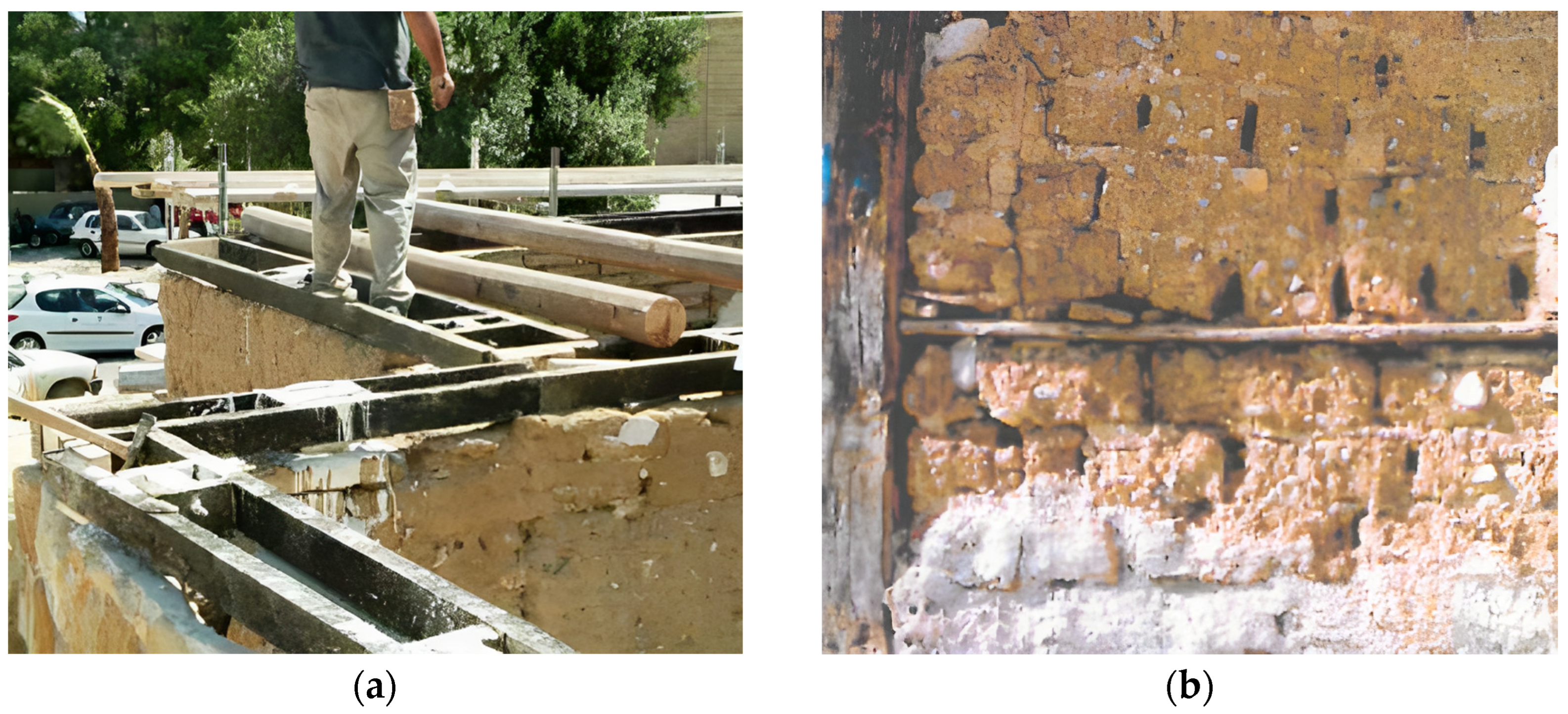
2. Behavior of Adobe Structures

Masonry structures are traditionally more massive than the reinforced concrete or steel structures that are more common today [21] and, due to that, they develop high seismic forces. In addition, the limited strength of the walls and the brittle behavior of the stone or adobe material act synergistically to cause high vulnerability in these kind of structures [22]. Typical modes of failure during earthquakes include the severe cracking and disintegration of walls, the separation of walls at the corners, and the separation of roofs from the walls [23]. Considering the modes of failure, it is of great importance to increase the ability of the walls to sustain seismic forces. The most common strengthening technology, which consequently improves the seismic performance of the masonry structures as load bearing systems, is the reinforcement of the walls [24]. The reinforcement will transmit the bending and inertia forces in transverse walls (out-of-plane) to the supporting shear walls (in-plane), restraining the shear stresses between adjoining walls and minimizing the vertical crack propagation [25].
Adobe walls are constructed of masonry blocks and are normally founded on stone strips of 0.50–1.00 m in height [26]. A traditional technique to provide reinforcement to the walls includes the installation of beams at the corners or on the perimeter of the buildings as a ring, spaced about every 0.60–1.00 m in height of the wall (Figure 1). The ring beams, also called tie-beams or seismic bands, are most commonly made of wood, concrete, steel, or straw bars and enable the structure to behave as a unit (box entity), which increases its structural resistance against lateral loads such as the seismic loads in earthquake-prone areas.
Through the use of wooden ring beams, which is the subject matter of this work, the in-plane capacity of a masonry wall increases and is more capable of resisting tensile and bending stresses. The wooden ring beams receive in-plane shear stresses, so any cracks caused by an earthquake are confined between layers of the ring beams and do not extend over the entire surface of the wall. Additionally, a continuous beam (most of the times as part of the roof) is installed on the top of the masonry wall, which prevents overturning and provides out-of-plane stiffness. A very important condition is the interlocking of the walls at the corners either via the installation of the ring beams (Figure 2), which is the most effective, or via the rearrangement of the adobe bricks. This technique will principally contribute to the structure’s performance in the plastic region. The proper installation of the ring beams prevents the separation of the walls from vibrations. It is important to note that weak connections, i.e., the use of round branches or poor-quality wood damaged by the vertical dowels or center core pins, hinders the ability of the structure to behave as a single unit (box entity).
The roof normally consists of a support construction of individual beams or trusses and is covered with clay tiles or sometimes with metal sheeting. The floor is made of earthen materials or cast plaster (screed). The roof and the floors are supported on the masonry walls for which they provide a lateral connection between them. The quality of the connection of the roof and floors to the supporting walls is essential as it develops diaphragmatic behavior. The effectiveness of the connection and the in-plane stiffness of the roof and floors dictate the level of the diaphragmatic behavior and affects the overall structural response to the lateral loads.

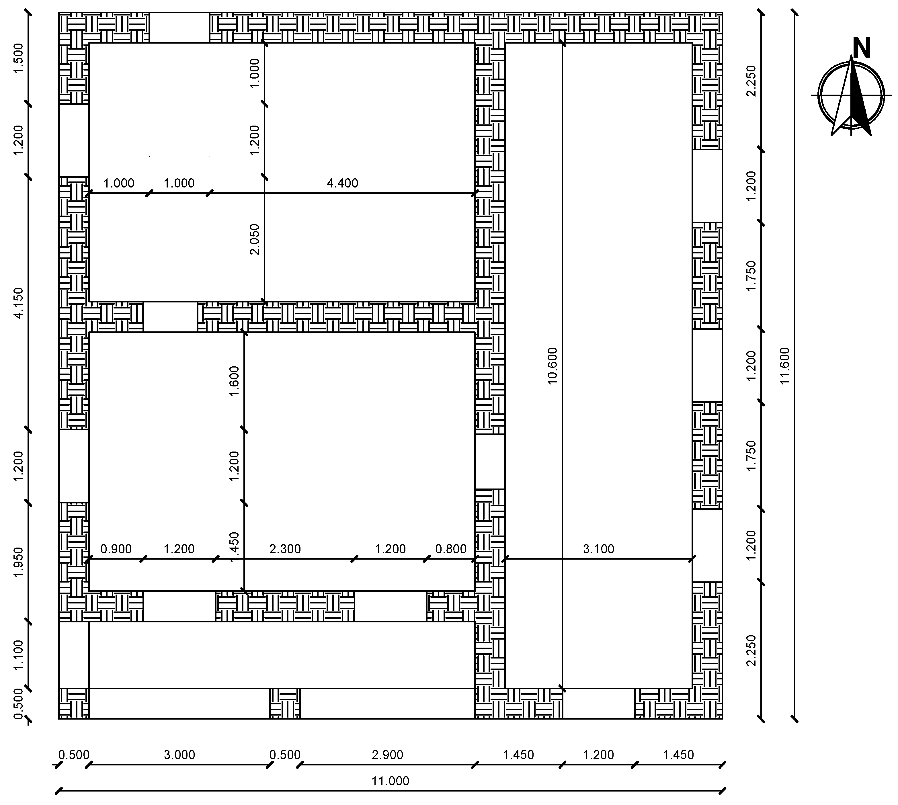
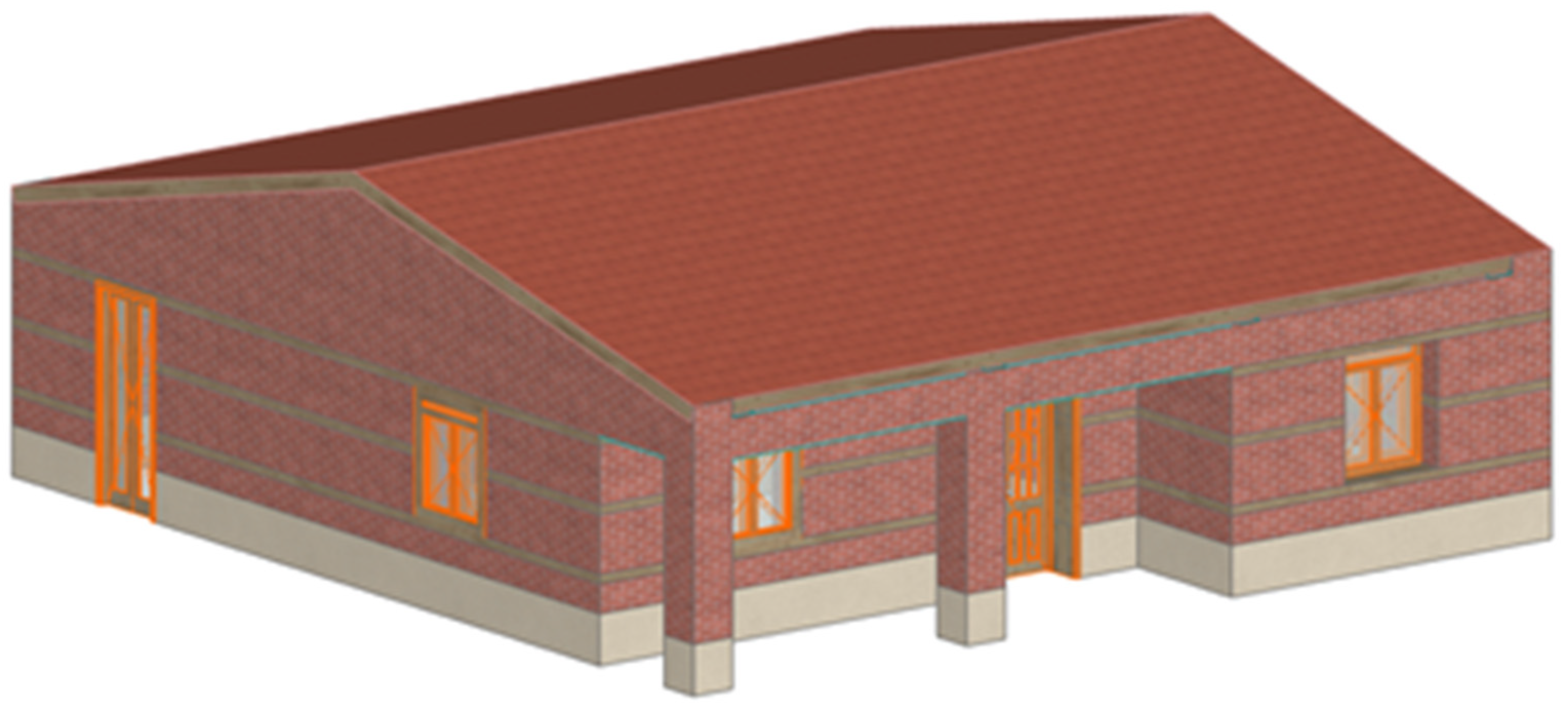
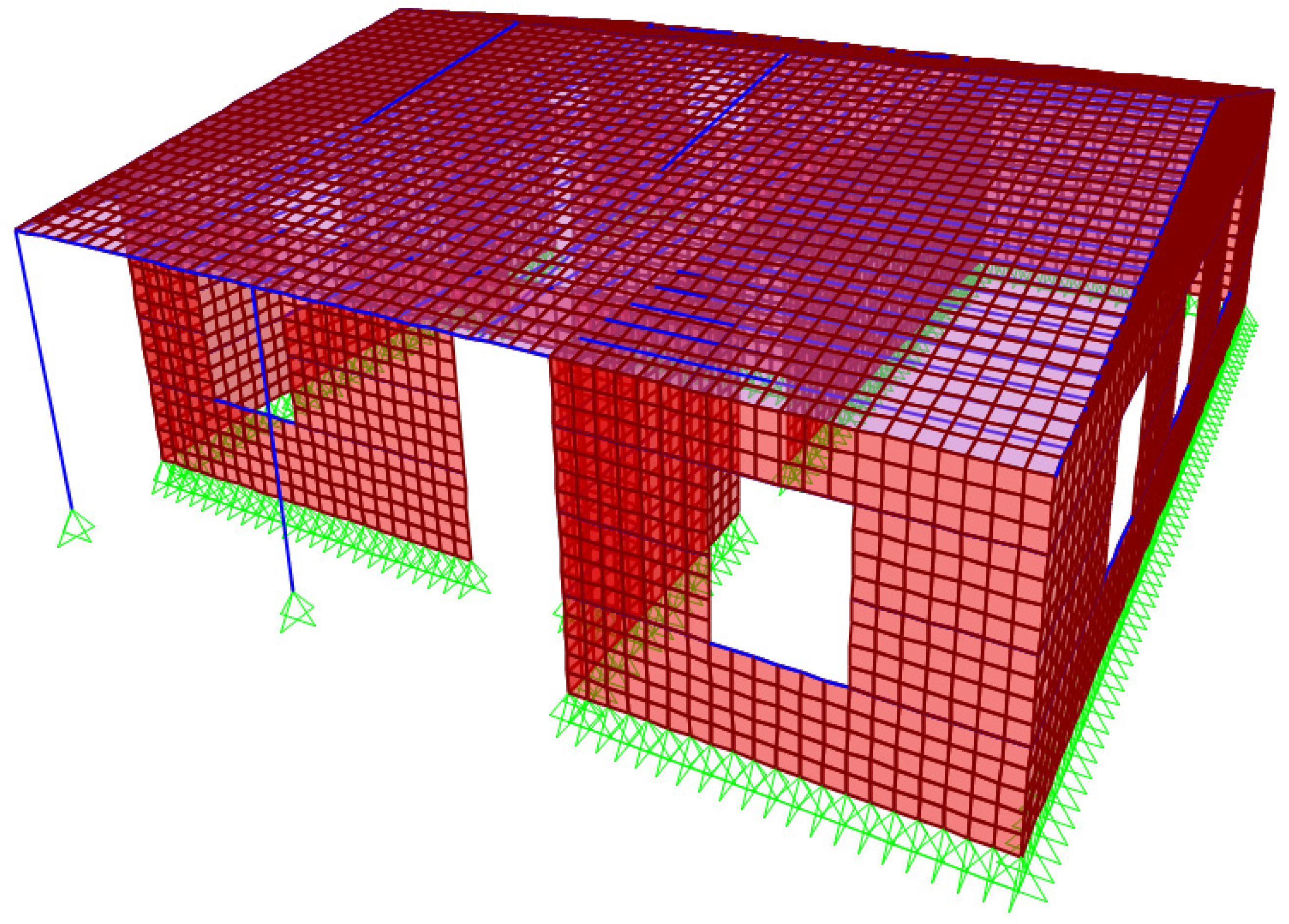
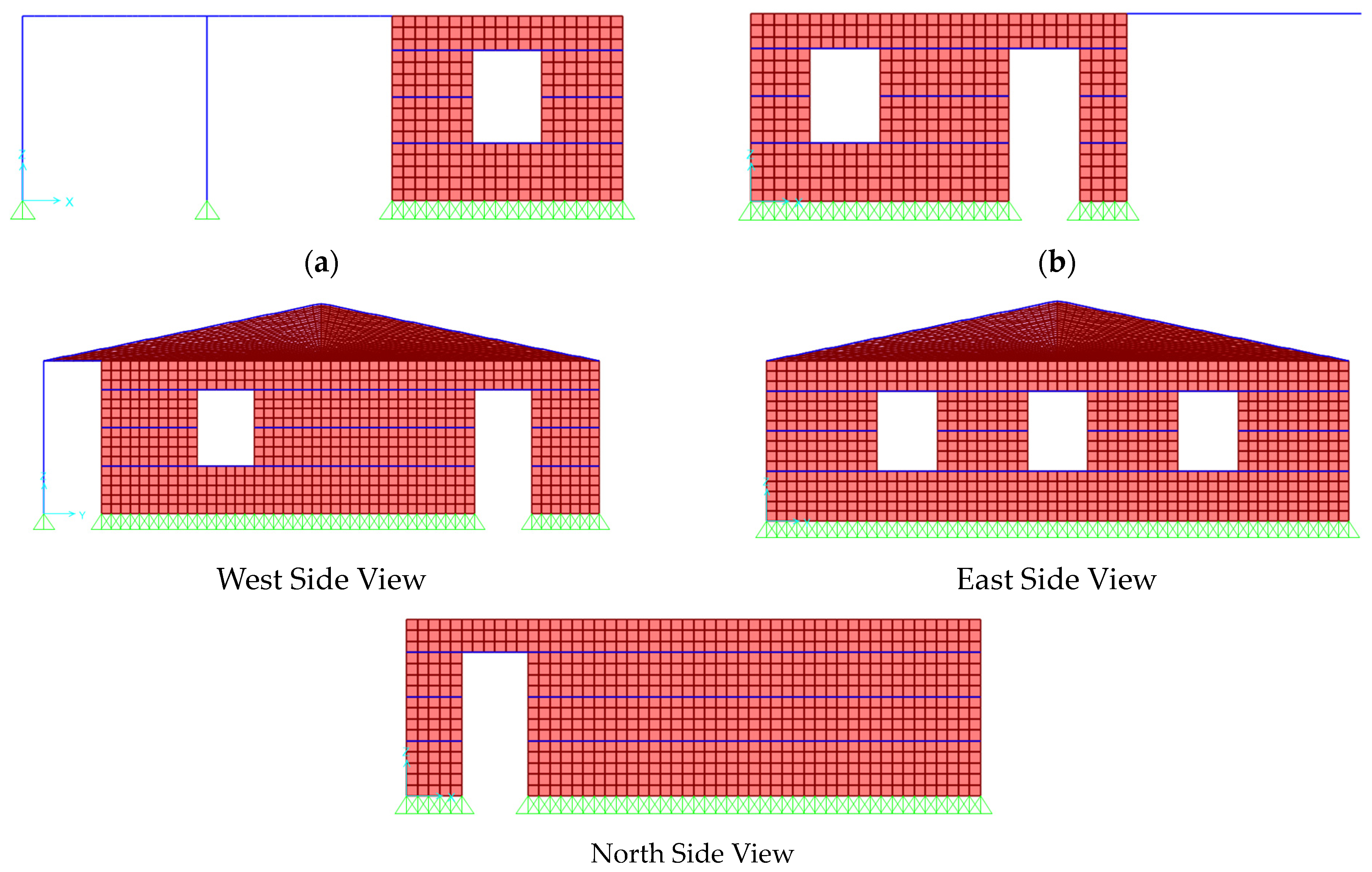
3. Simulation of the Case Study

Figure 3 shows the plan view (in meters) of the case study which refers to an adobe masonry building of 1920 located in Cyprus. The floor plan consists of three interior spaces enclosed by load bearing adobe walls and two columns supporting the roof of the patio. The area of the two smaller spaces is 6.40 m × 4.25 m each and the area of the larger space is 10.60 m × 3.10 m. The thickness of the walls is 0.50 m and the height is 3.20 m. The walls are founded on a strip of rubble stone 0.60 m in height. The façade to the north side incorporates a door opening with dimensions of 1.00 m × 2.60 m, which is typical for these type of structures. The south side incorporates a balcony door with dimensions of 1.20 m × 2.60 m and two windows that are 1.20 m × 1.60 m each. To the east, we find three windows that are 1.20 × 1.60 m, while the west side has a door that is 1.20 m × 2.60 m and a window that is 1.20 m × 1.60 m. Each wall is crowned with an oak beam measuring 0.2 m × 0.10 m. The roof structure features a timber truss system that rests on the load-bearing walls and the columns surrounding the patio, all topped with clay tiles for coverage. Wooden ring beams, with cross-sectional dimensions of 0.1 m × 0.1 m, are arrayed at intervals of 800 mm, with two tiers installed at each level of the structure. Both doors and windows are framed with timber, with the door frames being 0.1 m × 0.1 m and window frames being 0.05 m × 0.05 m. A 3D view of the structure is shown in Figure 4.
The calculations were performed using the software SAP2000 v23 and included the modelling of the same building with two different considerations:
  • Adobe bearing walls with no reinforcement. The assumption is made to model the response by considering a uniform configuration of the adobe bricks and the mortar;
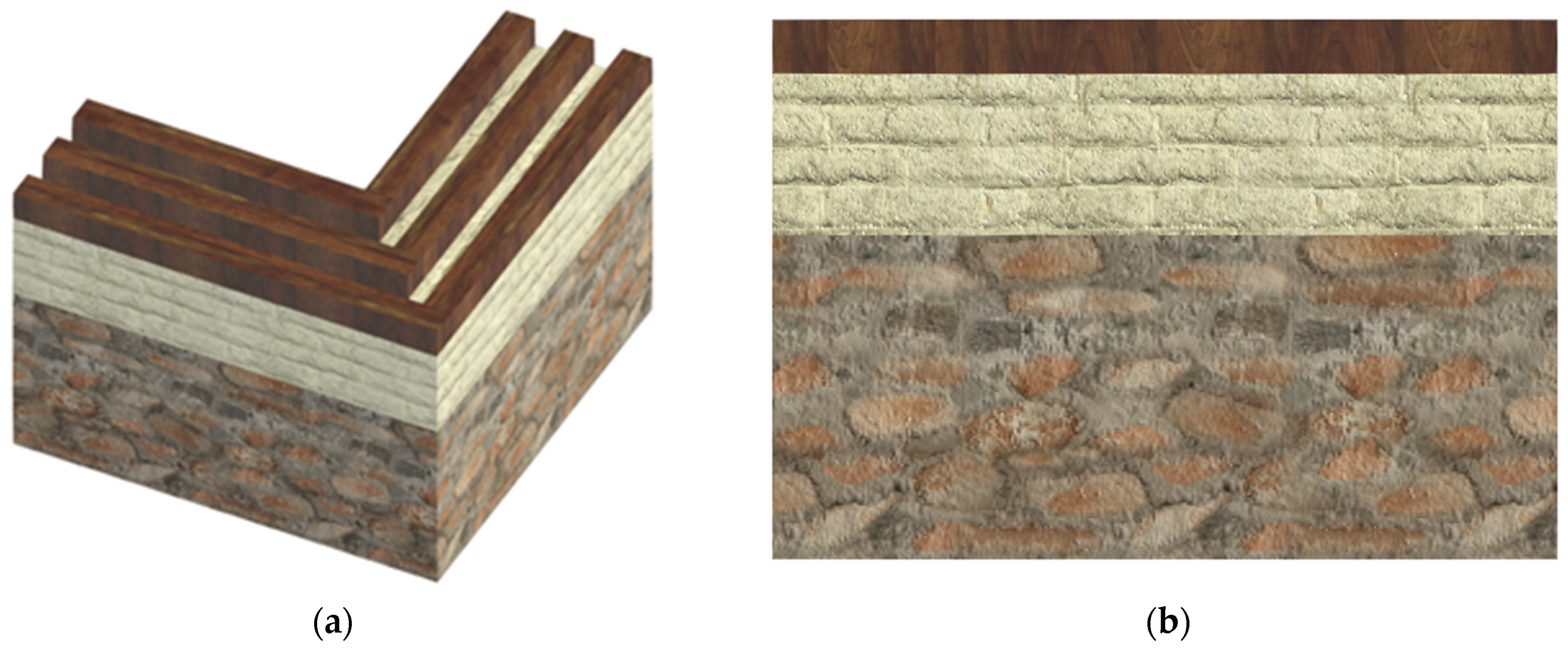
  • The walls are reinforced with ring beams made of wood. The assumption here is that the ring beams tie the walls together, maintaining their box-like behavior during an earthquake.
Based on the assumptions, a macro-modelling approach was followed, which is consistent with the pertinent literature [28,29,30,31,32,33,34]. This approach assumes a homogenization of the material parameters, a technique which is described in Eurocode 6, as opposed to the micro-modelling approach for which the bricks and mortar of the walls are modeled separately. The adobe and rubble stone masonry walls were simulated using layered shell elements implementing the Mindlin/Reissner formulation [35], which accounts for the shear deformations in the elements. In the analysis of layered shell elements [36], the non-linearity of the material is taken into consideration. The ring beams have been represented using frame elements, which have been subdivided into smaller segments at intervals of 20 cm. Additionally, two physical nodes have been established to enhance connectivity between the frame and shell elements. Frame elements were also used for the simulation of the elements consisting the wooden roof truss [37]. The connection of the roof truss to the walls is assumed to be rigid, allowing for diaphragmatic behavior. The boundary conditions for the foundation level were assumed to be pinned, primarily because there were no elements present on either the external or internal walls which can provide fixity. Additionally, as evidenced by a real case study, the lower portion of the masonry wall rests upon a strip foundation, with no structural connection established between the wall and the foundation.
Two different models were studied and compared in this work. Model 1 simulates the building with unreinforced walls, i.e., without the installation of the wooden ring beams, and Model 2 simulates the models with the ring beams acting as reinforcement to the walls. Table 1 shows the numerical modeling characteristics [38] for both modes, while Figure 5 and Figure 6 show the discretized analytical model.
In investigating the mechanical response of adobe blocks under various stress conditions, the stress–strain relationships for both compression and tension were characterized using polynomial expressions as proposed by Illampas and Parisi [39,40] and Lourenço and Caporale [41,42], respectively. These relationships are detailed in the work of Illampas et al. [43]. Young’s modulus, indicative of the material’s elasticity, was deduced from the stress–strain curves as a secant modulus extending to the yield point, with a calculated value of E = 18 MPa. The adobe blocks exhibited a compressive strength of fc = 1.2 MPa, with a corresponding strain at a peak stress of ecu = 0.1 mm/mm (Figure 7a). Given the granular constitution of adobes, a limited elastic behavior under compression was anticipated [44]; hence, a non-linear material response was presumed to initiate beyond 5% of the determined compressive strength. For tensile stresses, a linear elastic regime was assumed up to the maximum permissible stress, followed by a softening phase post-peak, in alignment with the observations by Illampas et al. [43] (Figure 7b). In the context of tensile strength within rubble stone masonry structures, the research work of Rezaie [45] et al. demonstrate a tensile strength that surpasses the standards proposed by both the Italian code [46] and the research conducted by Vanin et al. [47], which suggest a value of 0.04 MPa. The research by Brignola et al. [48] indicates that the actual tensile strength is approximately 0.05 MPa, thereby providing evidence for a higher baseline in tensile capacity for such materials. Table 2 analytically presents the mechanical properties of the materials employed in the analysis [49,50].
Modal analysis was initially performed to obtain the fundamental periods and the mode shapes of the vibration. In this process, the characteristics (i.e., Young’s modulus, density, and Poisson’s ratio) of the masonry were considered. Eurocode 8 and the Italian Building Code [51] suggest considering all vibration modes as having a modal participating mass ratio higher than 5%; therefore, in this case, the total participating mass ratio was computed considering a subset of two vibration modes. The results provide quite low values: in particular, in the longitudinal and transversal direction, the sum of Mp 5% is equal to 72% and 70%, respectively. The highest mass participation factor (~65%) was obtained in the first and second mode, respectively. In past research of the seismic vulnerability assessment of a monumental masonry building [52], the Mp 5% values are also relatively low with 64.9% and 58% in the two directions, and in another research study [53] for the non-linear finite element model (NLFEM) with the implementation of a flexible diaphragm, the range of mass participation of the first mode is between 73–78%.
In the corresponding modal shape, the deformations were concentrated along the sections perpendicular to the direction of the earthquake (side walls), which exhibits significant deformation at the mid-crest and above; at the same time, these side walls have limited participation in the structural motion. This verifies that the seismic response of masonry structures with flexible diaphragms is primarily governed via the out-of-plane motion of the sections orthogonal to the direction of the earthquake. The fundamental translation mode exhibited a period of 0.37 s, as recorded prior to the installation of the wooden ring beams in the model.
Subsequent to the modal analysis, two finite element models were developed for the scope of the time history analysis. A review of numerous journal articles [54,55,56,57,58,59,60,61] suggests that non-linear dynamic analysis, also known as time history analysis, is a suitable method for the seismic evaluation of masonry structures.
As already mentioned, Model 1 simulates the building with unreinforced walls, i.e., without the installation of the wooden ring beams, and Model 2 simulates the models with the ring beams acting as reinforcement to the walls. The finite element models in question were analyzed using seismic data from an earthquake that occurred near Paphos in January 2022 [62], as depicted in Figure 8. This earthquake lasted for 48 s with a Peak Ground Acceleration (PGA) of 0.4 m/s2;, equivalent to 0.04 g, peaking at 2.93 s. According to Cyprus’s National Annex [63] and its seismic zoning map, there is a 10% likelihood of exceeding a 0.2 g PGA within the next 50 years. For the purposes of this research, the seismic event from Paphos was scaled to a PGA of 0.2 g. The subsequent sections detail the outcomes and relevant analyses for the Paphos earthquake’s seismic record. It is important to note that the two models shared identical geometries, material mechanical properties, and loading conditions; thus, any discrepancies in the results can be ascribed to the inclusion of wooden ring beams.

4. Results and Discussion

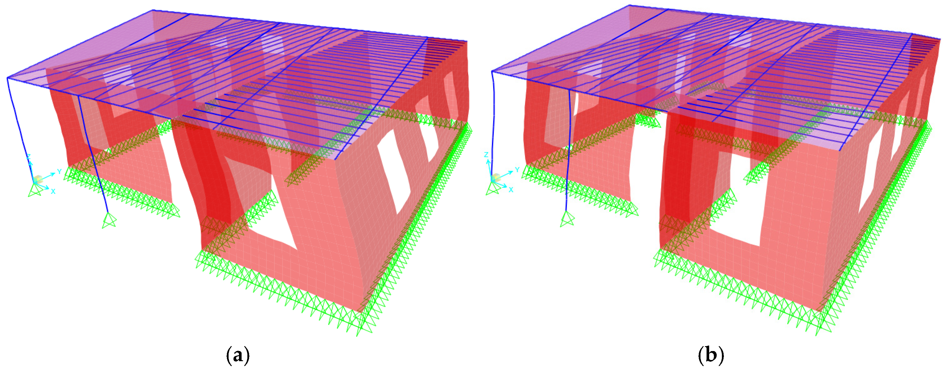
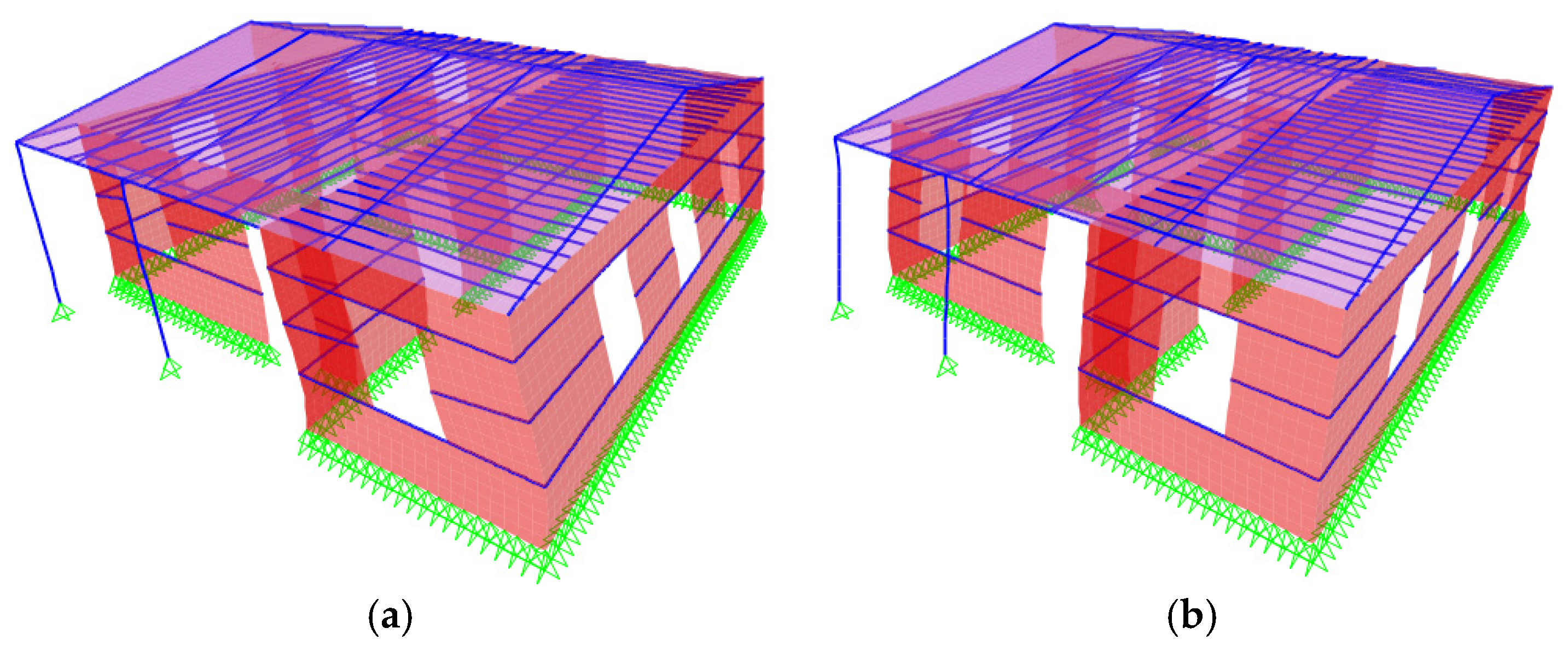
4.1. Modal Analysis—No Wooden Ring Beams

Figure 9a shows the first mode of Model 1. The building is shifting on the x-axis (East–West). The mass participation for this mode is 66% and the period, T = 0.37 s. Figure 9b shows the second mode of Model 1 with the building shifting along the y-axis (North–South). The mass participation for this mode is 70% and the period, T = 0.33 s.

4.2. Modal Analysis—With Wooden Ring Beams

Figure 10a shows the first mode of Model 2. The building is shifting on the x-axis (East–West). The mass participation for this mode is 67% and the period, T = 0.35 s. Figure 10b shows the second mode with the building shifting along the y-axis (North–South). The mass participation for this mode is 70% and the period, T = 0.31 s.
The structure exhibits behavior in accordance with standard engineering predictions, primarily attributed to the co-location of its centers of mass and stiffness. For structures of this classification, such an alignment is a direct consequence of the strategic mass distribution, primarily centralized within the load-bearing walls. These walls play a pivotal role in resisting lateral loads, owing to their substantial contribution to the structure’s inertia. Analyzing the structure’s dynamic behavior, its primary fundamental modes are evident: two translational degrees of freedom along the x and y axes. This characteristic modal response is commensurate with a majority of structures having a symmetrical mass and stiffness distribution.
A notable observation arises from the data in Table 3, which delineates a reduction in the structure’s fundamental periods by a range of 13% to 20%. This deviation in dynamic response can be attributed to the incorporation of wooden ring beams. From a structural dynamics’ perspective, these beams augment the lateral stiffness of the structure. However, it is essential to note that despite this augmentation, the modal characteristics of the structure remain largely invariant, implying that the global dynamic behavior remains consistent, even with localized stiffness modifications.

4.3. Comparison of Stress Results

This section elucidates the impact of wooden ring beams on the in-plane and out-of-plane stresses (kN/m2) generated during the analysis. As delineated in preceding sections, the natural frequency of model 1 (lacking wooden ring beams) is comparatively higher than that of model 2 (incorporating wooden ring beams). This observation implies that the stiffness of model 2 is greater, while the overall mass of the structure remains unaltered. Consequently, model 2 experiences heightened stresses, particularly at the stone masonry-based foundation. Furthermore, the presence of wooden ring beams causes a discernible alteration in the distribution pattern of stresses. Specifically, model 1 exhibits a shear pattern in the stress distribution, whereas model 2 demonstrates a horizontal stress pattern aligned in parallel with the ring beams.

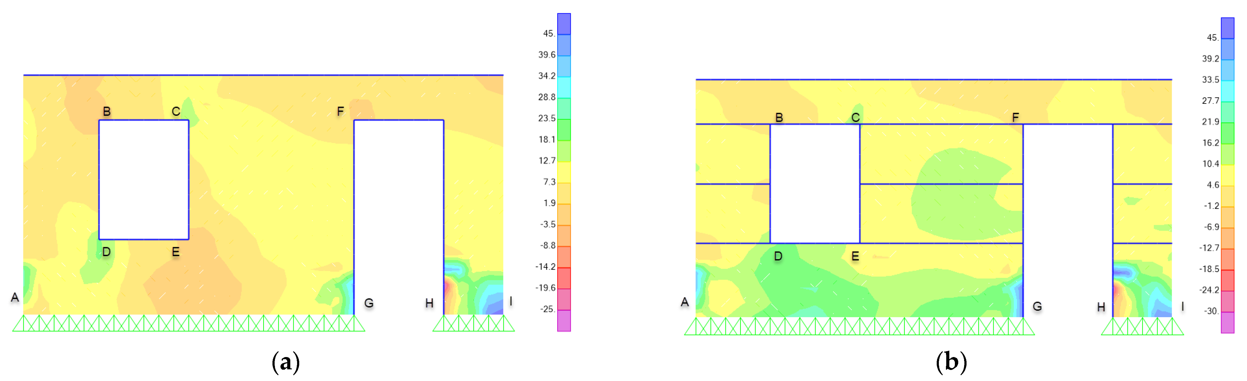
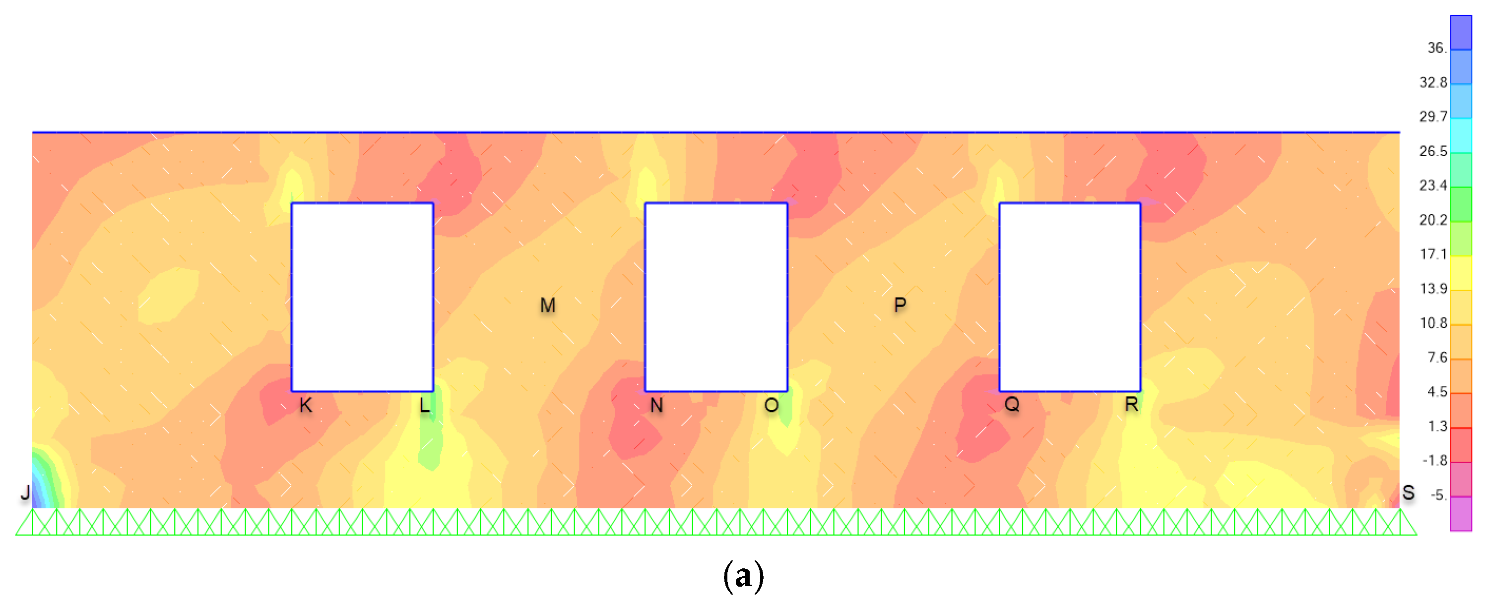
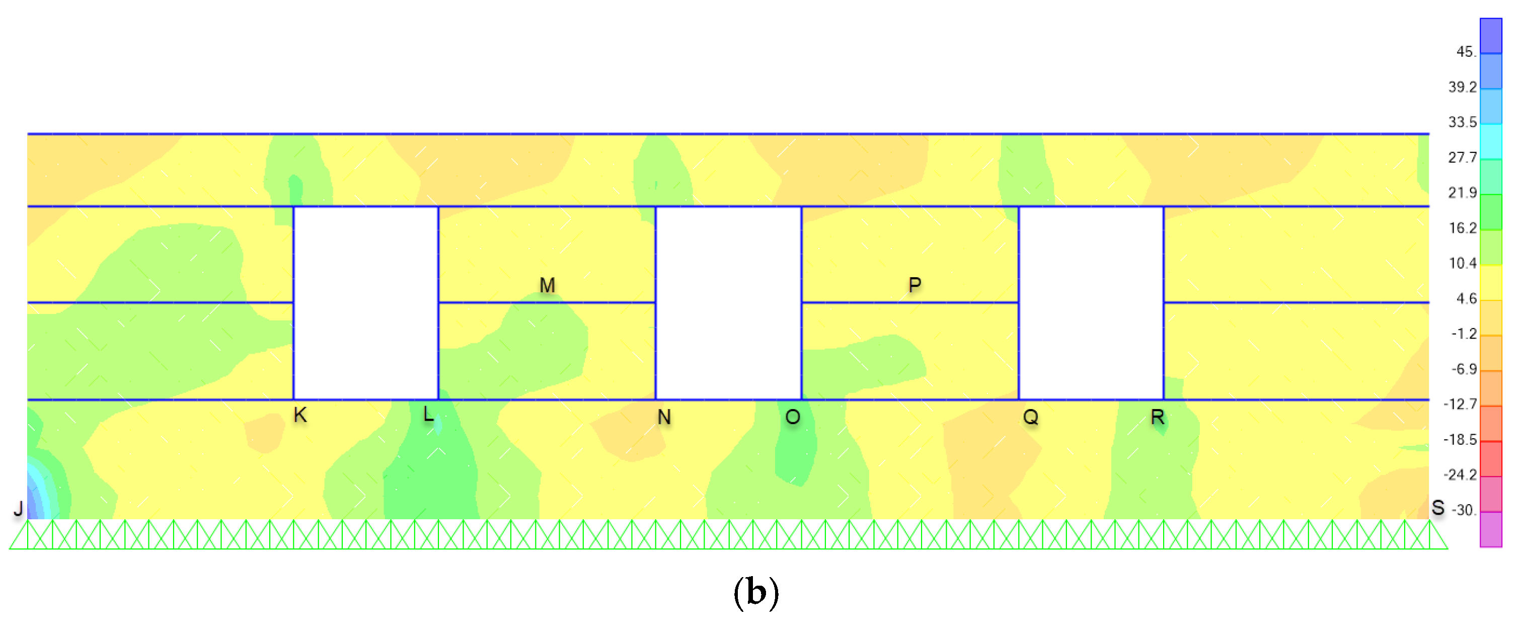
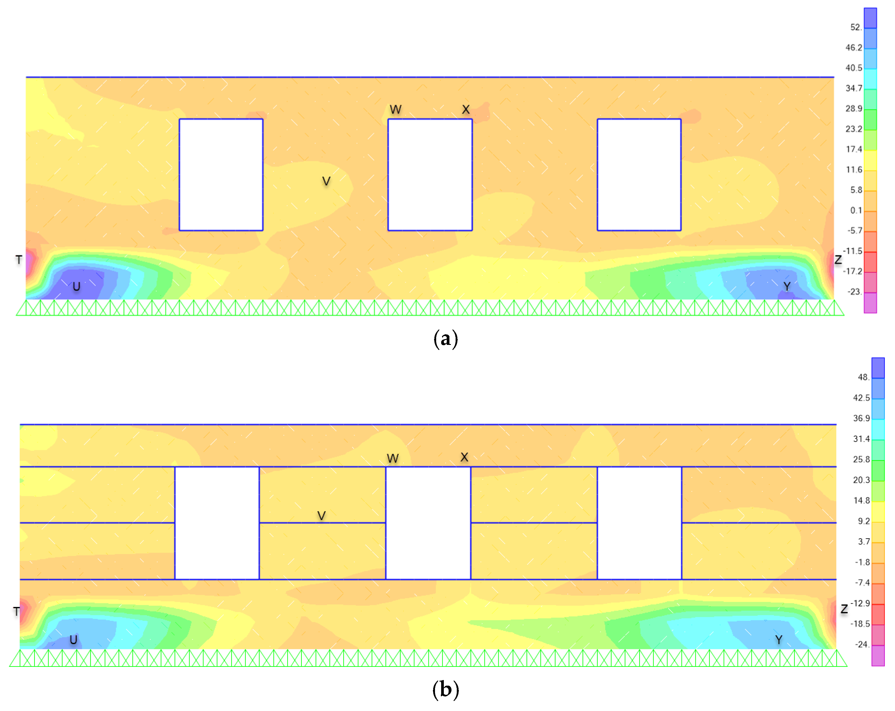
4.3.1. In-Plane Stresses

Figure 10 and Figure 11 present the in-plane stress distributions in the south and north walls, respectively. These stress patterns arise as a consequence of the seismic forces applied parallel to the walls’ direction. Upon examining the stress distributions depicted in Figure 11b and Figure 12b (model 2), a notable observation emerges: an intensified concentration of stresses occurs at the foundation level, specifically in the stone masonry, in comparison to the stress patterns depicted in Figure 11a and Figure 12a (model 1). Simultaneously, it is evident that model 2 exhibits lower stresses at the openings (e.g., doors, windows) and the primary wall.
Upon detailed analysis of the presented data, several key structural behaviors emerge. Model 1’s stress distribution distinctly portrays a modal or sigmoidal pattern, suggesting a varying concentration of stresses at different heights of the structure. On the other hand, Model 2 presents a more uniform stress profile across the entirety of its wall height. This consistent distribution, absent of pronounced stress concentrations or variations, points towards a more predictable and stable structural response. Crucially, this enhanced stability and uniformity in Model 2 can be directly attributed to the strategic integration of wooden ring beams within its design. These beams not only provide added reinforcement, but also ensure that the stresses are evenly distributed, culminating in a structure that demonstrates markedly superior performance characteristics when compared to Model 1.

4.3.2. Out-of-Plane Stresses

In Figure 13a,b, the out-of-plane stress distributions for the eastern walls are presented. These distributions originate from the induced forces of seismic activity acting transversely to the wall structures. A comparative examination of the out-of-plane versus in-plane behavioral trends indicates analogous characteristics with notable variations. Specifically, the stress distribution for out-of-plane conditions exhibits closely aligned values, which can be attributed to the horizontal ring beams acting in parallel to the wall plane, thereby offering marginal reinforcement to the system’s structural response.
Furthermore, it is critical to highlight the distinct morphologies in stress distribution between the two investigated models. Model 1 displays an “S”-shaped stress pattern, whereas Model 2 presents a shear-dominated stress profile. These patterns are in direct correlation with the anticipated stress behaviors within their respective planes, underscoring the intrinsic differences in structural response between the two models.
The aforementioned insights of Section 4.3 are confirmed by the data presented in Table 4, which details the stress levels in various sections of the building. This table serves as a comprehensive resource, extending the understanding beyond the graphical representations provided in the figures. It quantifies the stress distribution, thereby offering a clearer perspective on the structural integrity throughout different parts of the building.

5. Conclusions

This study aims to examine the mechanical behavior of unreinforced adobe masonry edifices and numerically ascertain the effects of integrating wooden ring beams on their global structural robustness and behavior. Through the employment of finite element models, this research numerically probed the structural responses of adobe constructions both with and without wooden ring beams. The subsequent findings prompt several prominent revelations:
  • The integration of ring beams augments the rigidity of the structure, resulting in a reduction in the fundamental period by approximately 6%. This intensifies the stresses, which is then predominantly redirected to the foundation level. Despite this increment at the foundation, it is typically fashioned from stone masonry, boasting superior resistance compared to the adobe walls. Conversely, the adobe walls, which inherently possess lower resistance, exhibit diminished stresses.
  • During seismic events, ring beams play a crucial role in reinforcing the structural integrity of walls by effectively “binding” the components together. This integration helps to maintain the unity of the structure when subjected to lateral forces parallel to the walls. Additionally, ring beams serve to mitigate stress concentrations around openings such as doors and windows, leading to a more uniform distribution of seismic forces and thus enhancing the resilience of the structure to earthquake-induced stresses.
  • In contrast, the efficacy of ring beams becomes negligible when the seismic direction is orthogonal to the walls, inducing out-of-plane stresses. Given that these beams are embedded within the wall, their performance becomes inconsequential in the out-of-plane direction, essentially moving in tandem with the entire wall without contributing significantly.
  • Recognizing that seismic activities are unlikely to be perfectly aligned with a building’s primary axes, ring beams are subjected to both in-plane and out-of-plane stresses. Consequently, they play a pivotal role in the structure’s overall dynamic response in various seismic directions.
A pivotal observation pertains to stress distribution. In both in-plane and out-of-plane stress scenarios, the stress distribution in the beam-less model (Model 1) exhibits an “S”-shaped pattern. In contrast, the model with beams (Model 2) displays a shearing stress pattern, with peak stresses predominantly localized around the ring beams. This data corroborates the notion that ring beams substantially stiffen the structure, playing a central role in its overall mechanical response.
Given the significance of risk assessments for historical city centers worldwide, it is imperative to employ rigorous evaluation techniques. Utilizing the Pushover or the Incremental Dynamic Analysis (IDA) method can be instrumental in this regard. For the two structures previously discussed, the pushover and IDA methods can offer a comprehensive insight into their seismic behavior. By analyzing these structures under incrementally increasing dynamic loads, precise vulnerability curves can be derived. Expanding this approach to other historical buildings can further enhance our understanding, providing a foundation for data-driven conservation and safety decisions in historical urban settings.

Author Contributions

Conceptualization, G.X. and P.C.; methodology, G.X. and P.C.; software, G.X. and P.C.; validation, P.C., D.P. and N.K.; formal analysis, G.X.; investigation, G.X.; resources, G.X.; data curation, P.C.; writing—original draft preparation, G.X.; writing—review and editing, P.C., D.P. and N.K.; visualization, G.X.; supervision, P.C.; project administration, P.C.; funding acquisition, P.C. All authors have read and agreed to the published version of the manuscript.

Funding

This research work was supported by the ISTOS project. This project has received funding from the European Union’s Horizon 2020 research and innovation programme (WIDESPREAD-TWINNING) under grant agreement No. 952300.

Data Availability Statement

Data are contained within the article.

Conflicts of Interest

The authors declare no conflict of interest.

References

  1. Pecchioli, L.; Panzera, F.; Poggi, V. Cultural heritage and earthquakes: Bridging the gap between geophysics, archaeoseismology and engineering. J. Seismol. 2022, 24, 725–728. [Google Scholar] [CrossRef]
  2. Guadagnuolo, M.; Faella, G. Simplified Design of Masonry Ring-Beams Reinforced by Flax Fibers for Existing Buildings Retrofitting. Buildings 2020, 10, 12. [Google Scholar] [CrossRef]
  3. Anzani, A.; Cardani, G.; Condoleo, P.; Garavaglia, E.; Saisi, A.; Tedeschi, C.; Tiraboschi, C.; Valluzzi, M.R. Understanding of historical masonry for conservation approaches: The contribution of Prof. Luigia Binda to research advancement. Mater. Struct. 2018, 51, 140. [Google Scholar] [CrossRef]
  4. Xekalakis, G.; Christou, P. Tracing the Historical Development of Architecture in Cyprus and its Resilience to Seismic Hazards. Int. J. Archit. Eng. Technol. 2023, 10, 1–15. [Google Scholar] [CrossRef]
  5. Cocco, G.; Brando, G.; Spacone, E. A review of local construction practices applied on unreinforced adobe buildings in South America. Front. Built Environ. 2022, 8, 974005. [Google Scholar] [CrossRef]
  6. Mauricio, A.C.; Grieseler, R.; Heller, A.R.; Kelley, A.R.; Rumiche, F.; Sandweiss, D.H.; Viveen, W. The earliest adobe monumental architecture in the Americas. Proc. Natl. Acad. Sci. USA 2021, 118, e2102941118. [Google Scholar] [CrossRef] [PubMed]
  7. Boyce, A.; Odoko, A. Adobe Brick, an Effective Construction Material. J. Sci. Multidiscip. Res. 2018, 10, 1. Available online: https://www.cenresinjournals.com/wp-content/uploads/2020/01/Page-1-9-1295.pdf (accessed on 4 October 2023).
  8. Sabo, Y.A. Comparative Study between Adobe Buildings in Northern Nigeria and Turkey. Adobe Material Construction. 2020. Available online: https://www.academia.edu/44996092/COMPARATIVE_STUDY_BETWEEN_ADOBE_BUILDINGS_IN_NORTHERN_NIGERIA_AND_TURKEY (accessed on 4 October 2023).
  9. Kafodya, I.; Okonta, F.; Kloukinas, P. Role of fiber inclusion in adobe masonry construction. J. Build. Eng. 2019, 26, 100904. [Google Scholar] [CrossRef]
  10. Rafi, M.M.; Khan, S.; Bhutto, M.A. Experimental Assessment of Mechanical Properties of Adobe Masonry. J. Mater. Civ. Eng. 2023, 35, 04023319. [Google Scholar] [CrossRef]
  11. Wang, H.; Yuan, K.; Zhang, S.; Guo, J. Experimental Study on the Seismic Behavior of a Modified Adobe-Brick-Masonry Composite Wall with a Wooden-Construction Center Column. Sustainability 2023, 15, 8360. [Google Scholar] [CrossRef]
  12. Zhou, T.; Xin, W.; Ma, B.; Zhang, Z.; Tan, W. Seismic performance of new adobe bricks masonry: Design and experiment. Adv. Struct. Eng. 2021, 25, 277–289. [Google Scholar] [CrossRef]
  13. Tunalı, S. Adobe Structures as Our Cultural Heritage and Their Features. Eur. Sci. J. 2015, 1, 1857–7881. Available online: https://eujournal.org/index.php/esj/article/view/5076/4848 (accessed on 4 October 2023).
  14. Işık, E. Structural Failures of Adobe Buildings during the February 2023 Kahramanmaraş (Türkiye) Earthquakes. Appl. Sci. 2023, 13, 8937. [Google Scholar] [CrossRef]
  15. Sánchez, A.; Varum, H.; Martins, T.; Fernández, J. Mechanical properties of adobe masonry for the rehabilitation of buildings. Constr. Build. Mater. 2022, 333, 127330. [Google Scholar] [CrossRef]
  16. Piani, T.L.; Weerheijm, J.; Peroni, M.; Sluys, L.J. Size Dependence and Dynamic Properties of Adobe Masonry Bricks tested at high strain rates. Epj Web Conf. 2021, 250, 06002. [Google Scholar] [CrossRef]
  17. Abdulla, K.F.; Cunningham, L.S.; Gillie, M. Out-of-plane strengthening of adobe masonry using hemp fibre ropes: An experimental investigation. Eng. Struct. 2021, 245, 112931. [Google Scholar] [CrossRef]
  18. Giamundo, V.; Lignola, G.; Prota, A.; Manfredi, G. Nonlinear Analyses of Adobe Masonry Walls Reinforced with Fiberglass Mesh. Polymers 2014, 6, 464–478. [Google Scholar] [CrossRef]
  19. Vilane, B.R.T. The Compressive Strength of Adobe Block Masonry Walls. Adv. Image Video Process. 2022, 10, 340–362. [Google Scholar] [CrossRef]
  20. Adobe Introduction. Adobe Introduction. [ONLINE]. 2023. Available online: https://www.world-housing.net/major-construction-types/adobe-introduction (accessed on 22 November 2023).
  21. Parajuli, R.R. Features and Seismic Response of Large Masonry Structures: A Case Study of Singh Durbar Main Building, Nepal. In Masonry Construction in Active Seismic Regions; Woodhead Publishing: Sawston, UK, 2021; Chapter 13; pp. 355–375. Available online: www.sciencedirect.com/science/article/pii/B9780128210871000132 (accessed on 8 November 2022). [CrossRef]
  22. Angelillo, M.; Lourenço, P.B.; Milani, G. Masonry behaviour and modelling. In Mechanics of Masonry Structures; Springer: London, UK, 2014; pp. 1–26. [Google Scholar] [CrossRef]
  23. Ismail, N.; Khattak, N. Observed failure modes of unreinforced masonry buildings during the 2015 Hindu Kush earthquake. Earthq. Eng. Eng. Vib. 2019, 18, 301–314. Available online: https://0-link-springer-com.brum.beds.ac.uk/article/10.1007/s11803-019-0505-x (accessed on 9 November 2023). [CrossRef]
  24. Shrestha, H.; Pradhan, S.; Guragain, R. Experiences on Retrofitting of Low Strength Masonry Buildings by Different Retrofitting Techniques in Nepal. In Proceedings of the 15th World Conference on Earthquake Engineering, 15 WCEE, Lisbon, Portugal, 24–28 September 2012; Available online: https://www.semanticscholar.org/paper/Experiences-on-Retrofitting-of-Low-Strength-Masonry-Shrestha-Pradhan/f59326c75b4245a1c1ffb7bbf227221d46980f4e#citing-papers (accessed on 9 November 2023).
  25. Blondet, M.; Vargas, J.; Tarque, N.; Iwaki, C. Seismic resistant earthen construction: The contemporary experience at the Pontificia Universidad Católica del Perú. Inf. Construcción 2011, 63, 41–50. [Google Scholar] [CrossRef]
  26. Touliatos, P.G. Seismic Behaviour of Traditionally-Built Constructions. In Protection of the Architectural Heritage against Earthquakes; Petrini, V., Save, M., Eds.; International Centre for Mechanical Sciences; Springer: Vienna, Austria, 1996; Volume 359, Available online: https://0-link-springer-com.brum.beds.ac.uk/chapter/10.1007/978-3-7091-2656-1_3#citeas (accessed on 9 November 2023). [CrossRef]
  27. Illampas, R.; Ioannou, I.; Charmpis, D.C. Adobe: An environmentally friendly construction material. WIT Trans. Ecol. Environ. 2009, 120, 245–256. Available online: https://www.witpress.com/Secure/elibrary/papers/SDP09/SDP09024FU1.pdf (accessed on 9 November 2023).
  28. Ravichandran, N.; Losanno, D.; Parisi, F. Comparative assessment of finite element macro-modelling approaches for seismic analysis of non-engineered masonry constructions. Bull. Earthq. Eng. 2021, 19, 5565–5607. Available online: https://0-link-springer-com.brum.beds.ac.uk/content/pdf/10.1007/s10518-021-01180-3.pdf (accessed on 9 November 2023). [CrossRef]
  29. Asteris, P.G.; Antoniou, S.T.; Sophianopoulos, D.S.; Chrysostomou, C.Z. Mathematical Macromodeling of Infilled Frames: State of the Art. J. Struct. Eng. 2021, 137, 1508–1517. [Google Scholar] [CrossRef]
  30. Valente, M. Earthquake response and damage patterns assessment of two historical masonry churches with bell tower. Eng. Fail. Anal. 2023, 151, 107418. [Google Scholar] [CrossRef]
  31. Valente, M. Seismic behavior and damage assessment of two historical fortified masonry palaces with corner towers. Eng. Fail. Anal. 2022, 134, 106003. [Google Scholar] [CrossRef]
  32. Tomić, I.; Vanin, F.; Božulić, I.; Beyer, K. Numerical Simulation of Unreinforced Masonry Buildings with Timber Diaphragms. Buildings 2021, 11, 205. [Google Scholar] [CrossRef]
  33. Ahmadi, S.S.; Karanikoloudis, G.; Mendes, N.; Illambas, R.; Lourenço, P.B. Appraising the Seismic Response of a Retrofitted Adobe Historic Structure, the Role of Modal Updating and Advanced Computations. Buildings 2022, 12, 1795. [Google Scholar] [CrossRef]
  34. Christoforo, A.L.; Gomes, A.F.F.; Arroyo, F.N.; Mascarenhas, F.J.R.; dos Santos, H.F.; Topolniak, L.; Akasaki, J.L. Reinforcement of Timber Beams with Steel Bars: Parametric Analysis Using the Finite Element Method. Buildings 2022, 12, 1036. [Google Scholar] [CrossRef]
  35. Hughes, T.J.; Franca, L.P. A mixed finite element formulation for Reissner-mindlin plate theory: Uniform convergence of all higher-order spaces. Comput. Methods Appl. Mech. Eng. 1988, 67, 223–240. [Google Scholar] [CrossRef]
  36. Layered Shells—Technical Knowledge Base—Computers and Structures, Inc.—Technical Knowledge Base. Layered Shells—Technical Knowledge Base—Computers and Structures, Inc.—Technical Knowledge Base. [ONLINE]. 2023. Available online: https://wiki.csiamerica.com/display/kb/Layered+shells (accessed on 22 November 2023).
  37. Tarque, N.; Camata, G.; Spacone, E.; Blondet, M.; Varum, H. The Use of Continuum Models for Analyzing Adobe structures. Available online: https://www.iitk.ac.in/nicee/wcee/article/WCEE2012_0128.pdf (accessed on 4 November 2022).
  38. Xekalakis, G.; Christou, P. The Contribution of Wooden Ring Beams to the Response of the Adobe Structures. Proc. Int. Struct. Eng. Constr. 2022, 9. [Google Scholar] [CrossRef]
  39. Illampas, R.; Ioannou, I.; Charmpis, D.C. Adobe bricks under compression: Experimental investigation and derivation of stress–strain equation. Constr. Build. Mater. 2014, 53, 83–90. [Google Scholar] [CrossRef]
  40. Parisi, F.; Asprone, D.; Fenu, L.; Prota, A. Experimental characterization of Italian composite adobe bricks reinforced with straw fibers. Compos. Struct. 2015, 122, 300–307. [Google Scholar] [CrossRef]
  41. Lourenço, P.B. Anisotropic Softening Model for Masonry Plates and Shells. J. Struct. Eng. 2020, 126, 1008–1016. [Google Scholar] [CrossRef]
  42. Caporale, A.; Parisi, F.; Domenico Asprone Luciano, R.; Prota, A. Critical surfaces for adobe masonry: Micromechanical approach. Compos. Part B Eng. 2014, 56, 790–796. [Google Scholar] [CrossRef]
  43. Illampas, R.; Charmpis, D.C.; Ioannou, I. Laboratory testing and finite element simulation of the structural response of an adobe masonry building under horizontal loading. Eng. Struct. 2014, 80, 362–376. [Google Scholar] [CrossRef]
  44. Meyer, C.S. Numerical Simulations of the Mechanical Behavior of Adobe. In Dynamic Behavior of Materials; Chalivendra, V., Song, B., Casem, D., Eds.; Conference Proceedings of the Society for Experimental Mechanics Series; Springer: New York, NY, USA, 2013; Volume 1. [Google Scholar] [CrossRef]
  45. Rezaie, A.; Godio, M.; Beyer, K. Experimental investigation of strength, stiffness and drift capacity of rubble stone masonry walls. Constr. Build. Mater. 2020, 251, 118972. [Google Scholar] [CrossRef]
  46. MIT. Ministry of Infrastructures and Transportation, Circ. N. 617 of 2/2/2009: Istruzioni per L’applicazione Delle Nuove Norme Tecniche per Lecostruzioni di cui al Decreto Ministeriale 14 Gennaio 2008. Italy; MIT: Rome, Italy, 2009.
  47. Vanin, F.; Zaganelli, D.; Penna, A.; Beyer, K. Estimates for the stiffness, strength and drift capacity of stone masonry walls based on 123 quasi-static cyclic tests reported in the literature. Bull. Earthq. Eng. 2017, 15, 5435–5479. [Google Scholar] [CrossRef]
  48. Brignola, A.; Frumento, S.; Lagomarsino, S.; Podestà, S. Identification of Shear Parameters of Masonry Panels Through the In-Situ Diagonal Compression Test. Int. J. Archit. Herit. 2018, 3, 52–73. [Google Scholar] [CrossRef]
  49. Illampas, R.; Kyriakides, N.; Charmpis, D.C. Seismic Fragility Assessment of Traditional Adobe Masonry Buildings with Limited Stiffness. In Proceedings of the 16th European Conference on Earthquake Engineering, Thessaloniki, Greece, 18–20 June 2018; Available online: http://papers.16ecee.org/files/Fragility%20paper%20-%20Rev-RI.pdf (accessed on 15 June 2023).
  50. Ferreira Pinto, A.P.; Sena da Fonseca, B.; Vaz Silva, D. Mechanical characterization of historical rubble stone masonry and its correlation with the masonry quality assessment. Constr. Build. Mater. 2021, 281, 122168. [Google Scholar] [CrossRef]
  51. Eurocode 8: Design of Structures for Earthquake Resistance—Part 1: General Rules, Seismic Actions and Rules for Buildings. 1998. Available online: https://www.confinedmasonry.org/wp-content/uploads/2009/09/Eurocode-8-1-Earthquakes-general.pdf (accessed on 9 November 2023).
  52. Pande, G.N.; Middleton, J.; Kralj, B. (Eds.) Computer Methods in Structural Masonry—4: Fourth International Symposium, 1st ed.; CRC Press: Boca Raton, FL, USA, 1998. [Google Scholar] [CrossRef]
  53. De Angelis, A.; Maddaloni, G.; Pecce, M.R. Seismic Vulnerability Assessment of a Monumental Masonry Building. Infrastructures 2020, 5, 93. [Google Scholar] [CrossRef]
  54. Kollerathu, J.A.; Menon, A. Role of diaphragm flexibility modelling in seismic analysis of existing masonry structures. Structures 2017, 11, 22–39. [Google Scholar] [CrossRef]
  55. Masciotta, M.G.; Lourenço, P.B. Seismic Analysis of Slender Monumental Structures: Current Strategies and Challenges. Appl. Sci. 2022, 12, 7340. [Google Scholar] [CrossRef]
  56. Pinho, R. Nonlinear Dynamic Analysis of Structures Subjected to Seismic Action. In Advanced Earthquake Engineering Analysis; Springer: Vienna, Austria, 2007; pp. 63–89. [Google Scholar] [CrossRef]
  57. Orduña, A.; Ayala, A.G. Non-linear dynamic analysis of ancient masonry structures by 3D rigid block models. In Proceedings of the International Conference of Computational Methods in Sciences and Engineering 2015 (ICCMSE 2015), Athens, Greece, 20–23 March 2015. [Google Scholar] [CrossRef]
  58. Capanna, I.; Cirella, R.; Aloisio, A.; Di Fabio, F.; Fragiacomo, M. Operational Modal Analysis and Non-Linear Dynamic Simulations of a Prototype Low-Rise Masonry Building. Buildings 2021, 11, 471. [Google Scholar] [CrossRef]
  59. Radnić, J.; Matešan, D.; Harapin, A.; Smilović, M.; Grgić, N. Numerical Model for Static and Dynamic Analysis of Masonry Structures. In Advanced Structured Materials; Springer: Berlin/Heidelberg, Germany, 2012; pp. 1–33. [Google Scholar] [CrossRef]
  60. Zhuge, Y.; Thambiratnam, D.; Corderoy, J. Nonlinear Dynamic Analysis of Unreinforced Masonry. J. Struct. Eng. Asce 1998, 124, 270–277. [Google Scholar] [CrossRef]
  61. Cattari, S.; Calderoni, B.; Caliò, I.; Camata, G.; de Miranda, S.; Magenes, G.; Milani, G.; Saetta, A. Nonlinear modeling of the seismic response of masonry structures: Critical review and open issues towards engineering practice. Bull. Earthq. Eng. 2021, 20, 1939–1997. [Google Scholar] [CrossRef]
  62. Τμήμα Γεωλογικής Επισκόπησης | Σεισμοί. Τμήμα Γεωλογικής Επισκόπησης | Σεισμοί. [ONLINE]. 2023. Available online: https://www.moa.gov.cy/moa/gsd/gsd.nsf/All/9C6031249A34EB40C22587C8002454AB?OpenDocument (accessed on 22 November 2023).
  63. National Annex. Available online: https://www.cys.org.cy/images/eurocodes/Cyprus_National_Annex_to_CYS_EN_1998-1_2004_Including_A1_2013__Corrigendum_AC_2009_1.pdf (accessed on 8 November 2023).
Figure 1. (a) Installation of wooden ring beams during construction [27]; (b) position of wooden ring beams [26].
Civileng 04 00065 g001
Figure 2. (a,b) Wooden ring beams spaced 0.60–1.00 m across the height of the masonry wall, designed in Revit.
Civileng 04 00065 g002
Figure 3. Plan of the simulated structure.
Civileng 04 00065 g003
Figure 4. 3D model of the case study designed in ArchiCAD.
Civileng 04 00065 g004
Figure 5. 3D view of Finite Element model in SAP2000.
Civileng 04 00065 g005
Figure 6. 2D views of the Finite Element model in SAP2000. (a) South Side View; (b) South Side View.
Civileng 04 00065 g006
Figure 7. (a) Compressive stress–strain response of adobe; (b) tensile stress–strain response of adobe.
Civileng 04 00065 g007
Figure 8. Time vs. Acceleration record of seismic event considered in the study.
Civileng 04 00065 g008
Figure 9. (a) First Mode for Model 1 (Translational); (b) Second Mode for Model 1 (Translational).
Civileng 04 00065 g009
Figure 10. (a) First Mode for Model 2 (Translational); (b) Second Mode for Model 2 (Translational).
Civileng 04 00065 g010
Figure 11. Maximum In-Plane Stresses, South side: (a) Model 1; (b) Model 2.
Civileng 04 00065 g011
Figure 12. Maximum In-Plane Stresses, North side: (a) Model 1; (b) Model 2.
Civileng 04 00065 g012aCivileng 04 00065 g012b
Figure 13. Maximum out-of-plane stresses, west side: (a) Model 1; (b) Model 2.
Civileng 04 00065 g013
Table 1. Numerical modeling characteristics.
Model 1Model 2
Mesh size20 cm20 cm
No. of area elements179179
No. of frame elements83190
No. of nodes of each area element44
No. of joint restraints4141
Table 2. Mechanical properties of the structural materials.
Property TypeAdobeRubble Stone CypressClay Tiles
Density (kg/m3)130019375001400
Modulus of Elasticity (kNm−2)18,000500,00010,985,00014,000,000
Poisson ratio, U0.300.140.180.20
Shear Modulus, G (kNm−2)6923219,2984,654,6615,833,333
Table 3. Comparison of fundamental periods.
ConditionPeriod (Sec)
Mode 1Mode 2
Without Wooden Ring Beams0.370.33
With Wooden Ring Beams0.350.31
Reduction (%)5.5%6%
Table 4. Comparison of stresses.
LetterWithout TRB (kN/m2)With TRB (kN/m2)LetterWithout TRB (kN/m2)With TRB (kN/m2)
A2435N−2.41.8
B−2.90.7O19.3518.31
C15.9411.37P9.169.6
D1813.93Q−2.63.7
E−3.65.41R18.1815
F5.183.46S−2.63−5.5
G3546T−33−25
H−29−32U5245
I4245V65
J3645W8.17
K−2.474.59X−1.661.5
L20.8820.58Y5140
M9.110Z−26−18
Disclaimer/Publisher’s Note: The statements, opinions and data contained in all publications are solely those of the individual author(s) and contributor(s) and not of MDPI and/or the editor(s). MDPI and/or the editor(s) disclaim responsibility for any injury to people or property resulting from any ideas, methods, instructions or products referred to in the content.

