
Development of Energy Harvesting Device to Utilize the Vibrational Energy of the Vehicle Suspension Systems †

Department of Mechanical Engineering, G.H. Raisoni College of Engineering, CRPF Gate No. 3, Hingna Road, Digdoh Hills, Nagpur 440016, Maharashtra, India
†
Presented at the International Conference on Innovative Research in Renewable Energy Technologies, West Bengal, India, 16–17 March 2022.
Mater. Proc. 2022, 10(1), 10; https://0-doi-org.brum.beds.ac.uk/10.3390/materproc2022010010
Published: 5 August 2022
(This article belongs to the Proceedings of The 2nd International Conference on Innovative Research in Renewable Energy Technologies (IRRET 2022))
Abstract
:Conventional energy resources are depleting at a rapid rate and there exists a possibility that the future generations will suffer from the lack of these resources. In a similar vein, this study makes an effort to harness the energy from vehicle vibrations, which is currently being wasted. When the vehicles move on the road, a lot of vibration occurs, if this energy can be scavenged and stored, then it could be used in any practical application. To this end, this study focuses on the development of an energy harvesting device that captures energy from the vehicle vibrations by using a smart material like a piezoelectric transducer (PZT) sensor and converts this energy into electrical energy. Besides, this device can be installed on the suspension system of any vehicle.
1. Introduction
Globally, environmental pollution and energy scarcity have become serious concerns [1]. Thus, researchers and practitioners both are trying to develop ways to rectify the above situations by developing innovative techniques to gather even a small amount of energy from different places that is currently being wasted. This mechanism of accumulating the waste energy and utilizing this energy in different applications is known as energy harvesting [1,2]. Energy harvesting devices transform ambient energy into electrical energy in a variety of situations by using integrated electronic circuits [2,3]. Energy harvesting devices can be used to create an energy supply system that is self-sufficient. Wind energy, energy from flowing water, vibrational energy, solar energy, and thermal energy are all examples of energy that is being squandered every day without being properly utilized. To harness these energies, there is an immediate need to create a system that can convert the waste energy in to useful energy [4,5]. Due to its capability to convert the vibrations into electricity, piezoelectric materials have attracted attention and these materials are now being used for collecting electric energy from the surrounding environment which have led to the recent growth of the creation of low-power electronic devices. Since piezoelectric transducers (PZT) supply the rectified electric energy to power low-power electronic devices, an integrated circuit is necessary to enhance the piezoelectric transducer’s power output [6].
The suspension system, being an integral part of the vehicle chassis, supports the body and absorbs vibrations induced by uneven road surfaces [7]. The PZT-based energy harvesting device, developed in the present study, can be installed in the suspension system of the vehicle for harvesting the vibrational energy. When the piezoelectric transducer comes in contact with the clip connected to the terminals of the wires in the attached circuit, the vibrational energy is converted to electricity. This transformed electrical energy will be used to deliver power to other low-frequency devices.
2. Literature Review
There are various methods for converting mechanical energy from vibrating or moving sources into electrical energy such as electromagnetic induction, electrostatic induction, and the piezoelectric effect, etc. Among these methods, piezoelectric materials has highest energy density and higher flexibility of being integrated into a system and thus, these methods have been the most widely studied [8]. Hence, new energy harvesting devices are primarily being developed using piezoelectric materials [1]. Energy harvesting in self-powered systems is especially needed not only as a sustainable and cost-effective alternative to conventional energy resources, but it also helps in minimizing the environmental impact of excessive use of conventional energy resources.
Li et al. [8] studied different methods to develop and improve the power outputs from low-frequency applications (0–100 Hz) and concluded that despite the flexibility for the implementation of piezoelectric polymers, they do not possess good piezoelectric properties. Instead, PZT ceramics have better piezoelectric properties and are relatively cheaper. The authors have made some optimizations in the electronic circuits that enhanced the overall efficiency of power conversion. The obtained power can be utilized to power indicators of a vehicle, Micro-electromechanical systems (MEMS) devices, and Internet of Things (IoT) devices. Arivalagan and Lavanya [9] studied the future prospects of integrated circuits manufacturing and low power circuit design which can reduce the power requirements of a wireless sensor node to a level less than 1 mW. Minazara and Vasic [6] developed an energy harvesting device to absorb the vibrations from two-wheeler vehicle and the harvested power was measured as 3.5 mW for an optimal resistive load of 100 kΩ, which is sufficient to charge a battery, or to power low consumption devices. Songsukthawan et al. [10] experimented on the bicycle for energy harvesting and the findings showed that at a regular cycling speed, 13.6 mW power can be generated, which gives an electrical output of 11.5 V and 1.2 mA in terms of voltage and current, respectively. Besides, the results suggested that the weight of the cyclist does not affect the output energy. Al-Yafeai [1] conducted a comprehensive review of the different applications in which vibrational energy can be harvested. The main focus of the study was energy harvesting from the vehicle suspension system. The authors stated that for passenger cars traveling at a speed of 13 m/s, a dissipated power of around 200 W can be recorded from the suspension dampers.
Piezoelectric Effect
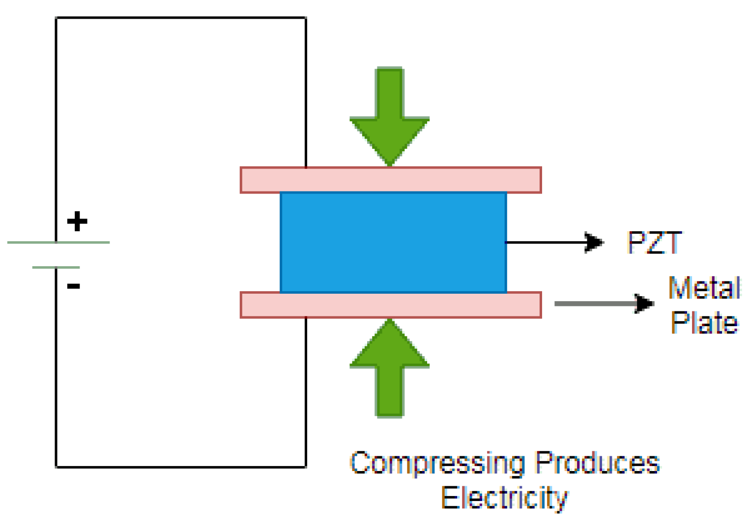
Piezo is a Greek word that means “push” [4]. The presence of an electrical potential across the surfaces of a crystal when mechanical stress is applied by squeezing it is known as piezoelectricity [7]. The crystal operates like a miniature battery in a system, with a positive charge on one side and a negative charge on the other. To make it a complete circuit (refer to Figure 1), the two faces are connected and the current is passed through it [11].
3. Materials and Methods
At first, the relevant literature has been searched and carefully studied to learn about the different mechanisms of energy harvesting. Based on the insights of the literature review, a suitable piezoelectric transducer, the components of the electronic circuit and a vehicle suspension were chosen to perform the experiment. The details of the components of the developed energy harvesting device are presented in next sections. The theoretical output voltage was then calculated and the prototype was optimized for the best output. Finally, the prototype was built and the output voltage was again investigated to ensure satisfactoriness of the output of the device.
3.1. Selection of the Components of the Device and the Suspension System
3.1.1. Selection of Suspension System
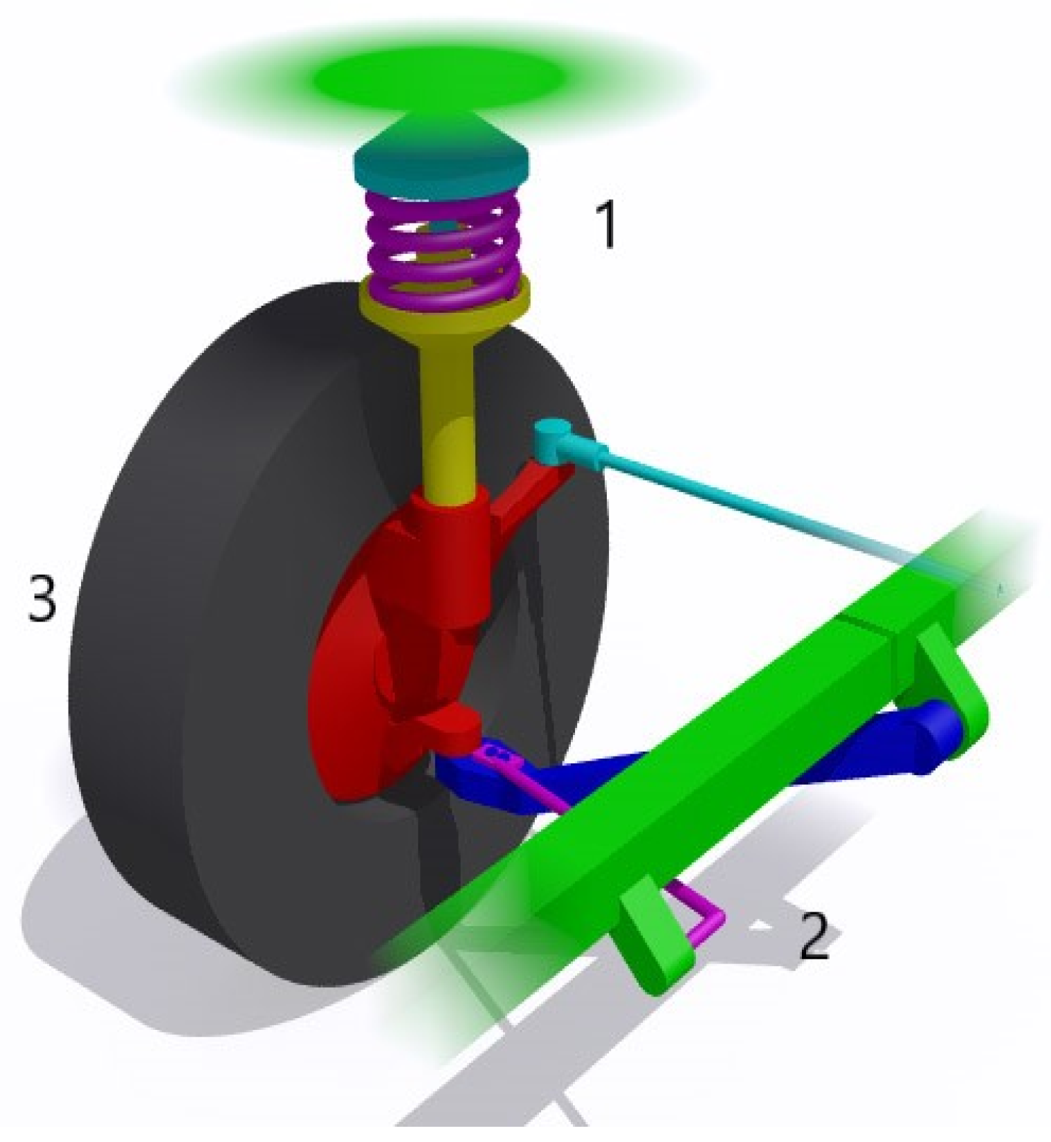
The McPherson suspension has been selected for the purpose of this study because the majority of vehicles are equipped with independent front suspension (McPherson Struts) and non-independent rear suspension (Torsion Beam) [2]. This suspension system (Figure 2) consists of: 1. suspension strut, 2. control arm and driveshaft, and 3. wheel assembly.
3.1.2. Selection of Piezoelectric Material
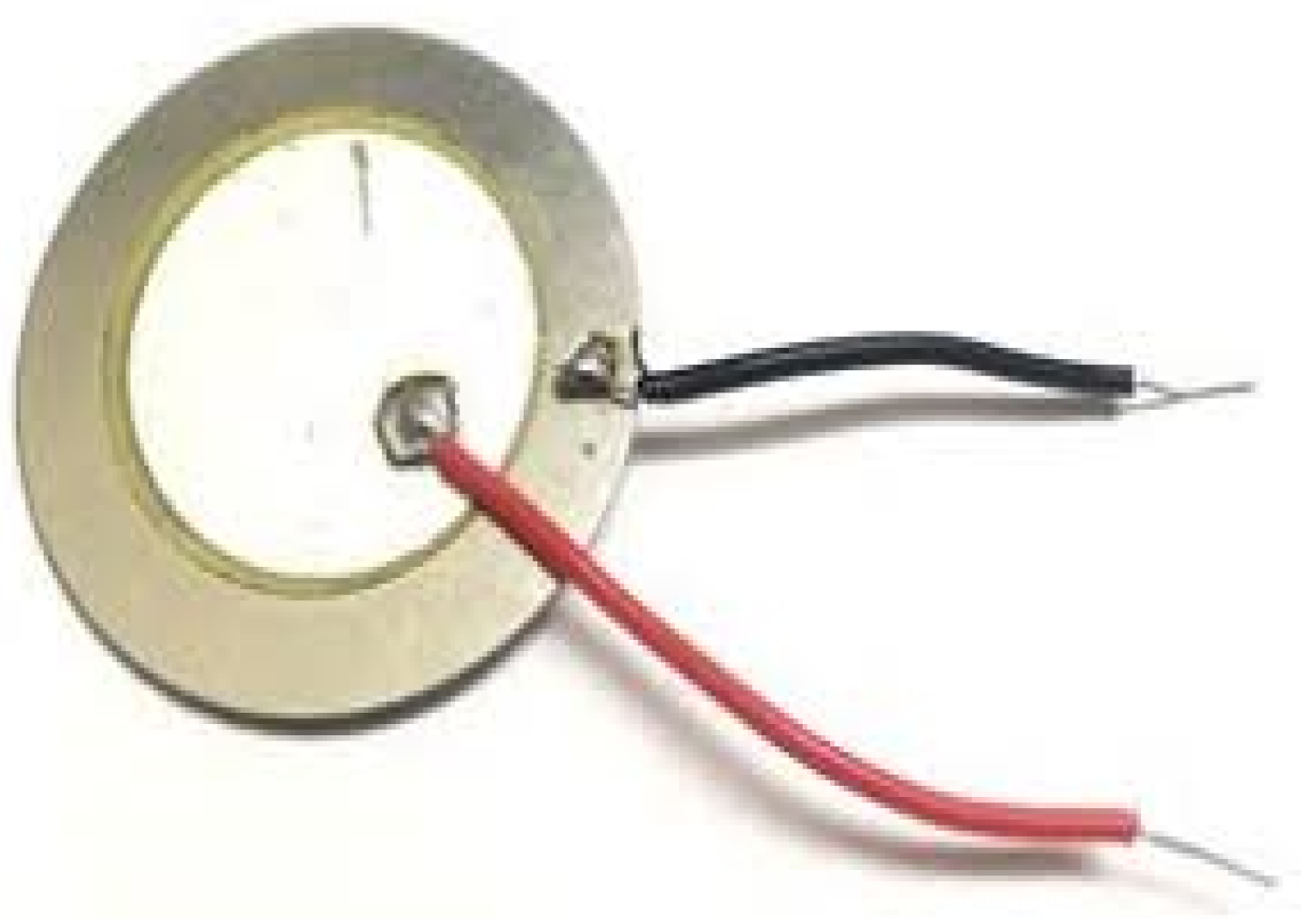
Polyvinylidene Fluoride (PVDF) is a polymer, while PZT is a ceramic, single crystals composite, both of which are some of the available piezoelectric materials. The PZT (refer to Figure 3) is capable of working at low voltages and can also withstand temperatures of more than 3000 °C. PZT produces more power than PVDF because it has a higher coupling coefficient, meaning it converts mechanical energy into electric energy efficiently, and possesses a greater charge constant [12]. In light of the above, PZT was chosen as the piezoelectric material. Since, the more porous the PZT is, the more energy can be harvested from it [13].
4. Results
4.1. Analysis of Suspension
In the present work, all the values related to the McPherson suspension spring of a 4-wheel car are taken from the manufacturer’s manual and presented in Table 1 [14].
Calculations for fixed end of film (end with polarities) with standard values (refer to Table 2 and Table 3):
- Stiffness of spring (K) = 12,000 N/m;
- Damping coefficient (C) = 1289.6 Ns/m;
- Kerb weight of vehicle = 1095 kg;
Assuming, the weight of 1 person = 60 kg.
For Rear suspension:
Case 1: Considering n persons;
Weight of n persons = 60 × n;
Here, the total weight (m) can be calculated as:
Weight of car + weight of n persons = 1095 + weight of n persons;
Around 60% of the total weight is acting on rear suspensions of the car;
Thus, load acting on rear suspension = M = 30% of total weight (m;)
M = 0.3 × m;
Let,
Natural frequency of spring = N;
Damping factor = £;
Critical damping Coefficient = Cc;
Damped vibration frequency= Nd;
Assuming, road surface is smooth.
£ = C/Cc;
Here, Cc = 2 × M × N
£ = 0.24
Nd = [√ (1 − £2)] × N
Refer to reference [15] for formulas.
For Front suspension:
Case 2: Considering n persons.
Weight of n persons = 60 × n;
Around 40% of the total weight is acting on front suspensions of the car;
Thus, the load acting on front suspension = M= 20% of total weight;
M = 0.2 × m;
Similar calculations were done in Case 2 as Case 1.
4.2. Analysis of Electrical Outputs
To achieve the maximum output from the piezoelectric sensors, they are coupled in a combination of series and parallel connections. Sensitivity of selected piezoelectric plate is taken as 0.9–1.0 V for 1.5 mm defection [16].
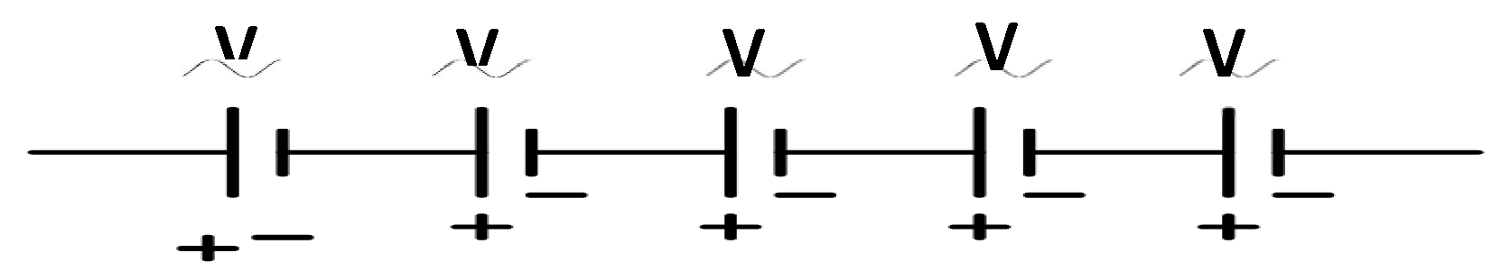
Case 1: For sensors (voltage sources) connected in series.
In the first case, 5 sensors are connected in a series combination (Figure 4).
As an equal amount of deflection is applied on each sensor the output voltage is also equal in each of the sensors.
Output voltage =Veq1 = V + V + V + V + V = 5 V.
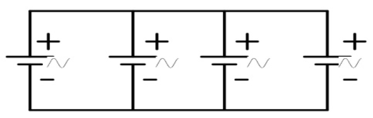
Case 2: For sensors (voltage sources) connected in parallel.
In the second case, 4 sensors are connected in parallel combinations (Figure 5).
The output voltage is constant, i.e., V in all the sensors.
Veq2 = V.
Thus, the total output voltage of the sensors = Veq = 5 V.
The output voltage of 5 volts, in both the cases, is sufficient to generate an appropriate level of electricity for charging portable batteries. To amplify the current and to convert it into DC, this circuit is linked to the booster circuit.
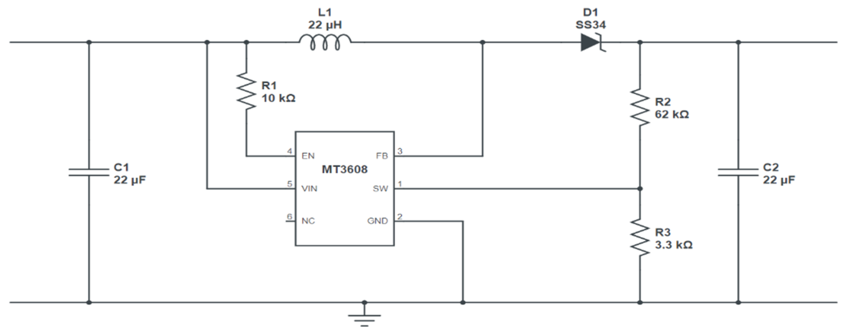
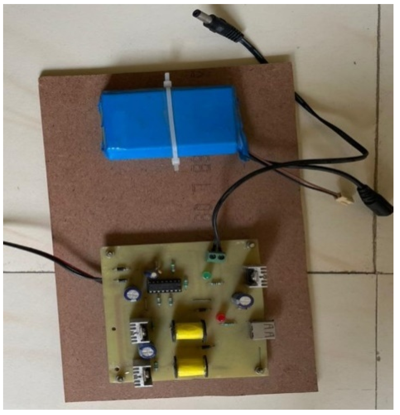
4.3. Booster Circuit
The circuit diagram of the boost converter is shown in Figure 6 and the actual image of the amplifying circuit with battery storage is shown in Figure 7.
The operating voltage of hardware is more than 10 V, the inductor coil is attached to step up which boosts voltage to 12 V. Initially, the current value is approximately 9 micro-amperes, this needed to be amplified, thus voltage and current regulators are provided to get output, i.e., 1.5 A. To convert AC to DC, diodes are used to rectify the alternating current waves. In MT3608, there is a MOSFET that will be turned OFF and ON to amplify the electronic signals generated in the circuit.
where,
Vref = 0.6 V;
R1 = 62 k;
R2 = 3.3 k……Refer [17];
Vout= 0.6;
Vout = 11.8 V.
4.4. Charging Time Required
A portable lithium-ion battery of mobile phones or power banks requires an input voltage from a range of 3.5 to 5 V.
Output voltage = 10–12 V;
Output Current = 1.5 A.
Battery specifications:
1. Battery Capacity: 4 Ah;
2. Charging capacity: 1.5–2 A.
Charging time (Tc) required:
Thus, from the above analysis, it can be concluded that a Li-ion battery will take 2.6 h to get 100% charged at constant voltage input from the vibrations while the vehicle is moving on a plain surface.
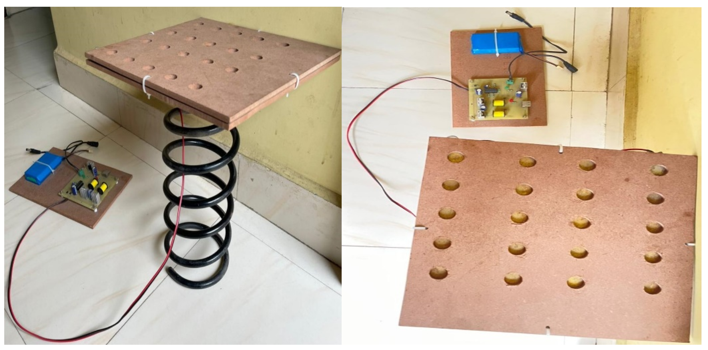
4.5. Development of Prototype
The objective of the study can be achieved by selecting the suitable suspension system, piezoelectric material, developing electrical circuit and combining all of these together to develop a prototype. The suspension spring is attached to the piezoelectric plate, and the wire from the piezoelectric plate is connected to the boost convertor circuit, which is then connected to a DC battery for energy storage that can be used in suitable applications (Figure 8).
4.6. Design of a 3D Model
For the final design, Catia V5 software (Vélizy-Villacoublay, France) has been used to create the components with proper dimensions and specifications. Further, the components were assembled to develop the model using the above software (Figure 9).
5. Discussion and Conclusions
The main objective of the present work is to transform the vehicle vibration into electrical output. To have an alternate energy source, a prototype was successfully developed that harvests vibrations from vehicle suspension and gives electrical energy as output, which can be stored in a battery and used for a variety of applications. In the recent studies, the experiments were mainly focused on bicycle and bike by using piezoelectric sensors, which could give output ranging from 3.5 mW to 13.6 mW. In contrast, the present work focuses on developing a device that can be installed in the four-wheel vehicle’s suspension. This prototype consists of 20 piezoelectric sensors (CEB-27D44) (CUI Devices, Tualatin, Ore, USA) connected in a series-parallel combination, but output voltage has been found low. The voltage output could be increased by increasing the number of piezoelectric sensors; however, this could be tested in future research. One of the major findings of the present work is that the number of passengers in a vehicle does not affect the output voltage because the stiffness of spring in suspension system is constant (12,000 N/m), which resists the deflection of suspension after a certain limit. During the analysis phase, the limit of deflection in various scenarios for both rear and front suspension is observed as 1.55 mm.
This prototype could prove useful in many applications such as power indicator lights, headlamps of a car and could also be used to power MEMS devices along with IoT devices. This proposed prototype could also be implemented in Light Motor Vehicles (LMVs) and Heavy Motor Vehicles (HMVs), which can open a range of applications in vehicle electronics system. Hopefully, the proposed device would decrease the dependency on conventional resources and also, it would render help in overcoming the power shortage and resource scarcity.
Funding
This research received no external funding.
Institutional Review Board Statement
Not applicable.
Informed Consent Statement
Not applicable.
Data Availability Statement
Not applicable.
Conflicts of Interest
The author declare no conflict of interest.
References
- Al-Yafeai, D.; Darabseh, T.; Mourad, A.H.I. A State-of-the-Art Review of Car Suspension-Based Piezoelectric Energy Harvesting Systems. Energy 2020, 13, 2336. [Google Scholar] [CrossRef]
- Hurel, J.; Mandow, A.; García-Cerezo, A. Kinematic and dynamic analysis of the McPherson suspension with a planar quarter-car model. Veh. Syst. Dyn. 2013, 51, 1422–1437. [Google Scholar] [CrossRef]
- Jayarathne, W.M.; Nimansala, W.A.T.; Adikary, S.U. Development of a vibration energy harvesting device using piezoelectric sensors. In 2018 Moratuwa Engineering Research Conference (MERCon); IEEE: New York, NY, USA, 2018; pp. 197–202. [Google Scholar]
- Colomer-Farrarons, J.; Miribel-Catala, P.; Saiz-Vela, A.; Samitier, J. A multi harvested self-powered system in a low-voltage low-power technology. IEEE Trans. Ind. Electron. 2010, 58, 4250–4263. [Google Scholar] [CrossRef]
- Vasic, D.; Chen, Y.Y.; Costa, F. Self-powered piezoelectric energy harvester for bicycle. J. Mech. Sci. Technol. 2014, 28, 2501–2510. [Google Scholar] [CrossRef]
- Minazara, E.; Vasic, D.; Costa, F. Piezoelectric generator harvesting bike vibrations energy to supply portable devices. In Proceedings of the International Conference on Renewable Energies and Power Quality (ICREPQ’08), Santander, Spain, 12–14 March 2008. [Google Scholar]
- Safaei, M.; Sodano, H.A.; Anton, S.R. A review of energy harvesting using piezoelectric materials: State-of-the-art a decade later (2008–2018). Smart Mater. Struct. 2019, 28, 113001. [Google Scholar] [CrossRef]
- Li, H.; Tian, C.; Deng, Z.D. Energy harvesting from low frequency applications using piezoelectric materials. Appl. Phys. Rev. 2014, 1, 041301. [Google Scholar] [CrossRef] [Green Version]
- Arivalagan, M.; Lavanya, M. Piezotransducer generator Energy Harvesting Bike Vibrations. Int. J. Emerg. Technol. Innov. Eng. 2015, I, 2394–6598. [Google Scholar]
- Jettanasen, C.; Songsukthawan, P.; Ngaopitakkul, A. Development of Micro-Mobility Based on Piezoelectric Energy Harvesting for Smart City Applications. Sustainability 2020, 12, 2933. [Google Scholar] [CrossRef] [Green Version]
- Elecrteical Technology. Available online: https://www.electricaltechnology.org/2020/05/piezoelectric-sensor.html (accessed on 8 June 2021).
- Dutta, M.; Shrimoyee, P. Footstep voltage generator using piezo-electric transducers. Int. J. Sci. Eng. Res. 2017, 8, 117–120. [Google Scholar]
- Zhang, Y.; Xie, M.; Roscow, J.; Bao, Y.; Zhou, K.; Zhang, D.; Bowen, C.R. Enhanced pyroelectric and piezoelectric properties of PZT with aligned porosity for energy harvesting applications. J. Mater. Chem. A 2017, 5, 6569–6580. [Google Scholar] [CrossRef] [PubMed] [Green Version]
- Dixon, J.C. The Shock Absorber Handbook; John Wiley & Sons: Hoboken, NJ, USA, 2008. [Google Scholar]
- Introduction to Dynamics and Vibrations. Available online: https://www.brown.edu/Departments/Engineering/Courses/En4/Notes/vibrations_free_damped/vibrations_free_damped.htm (accessed on 3 July 2021).
- Piezoelectric Materials. Available online: https://www.intechopen.com/books/5215 (accessed on 8 June 2021).
- 5 V to 12 V Boost Convertor Circuit. Available online: https://www.gadgetronicx.com/5v-12v-dc-boost-converter/ (accessed on 12 June 2021).
Figure 1.
Piezoelectric effect.

Figure 2.
McPherson strut suspension system.

Figure 3.
PZT sensor.

Figure 4.
Voltage sources connected in series.

Figure 5.
Voltage sources connected in parallel.

Figure 6.
Circuit diagram of 5 V to 12 V boost converter.

Figure 7.
Image of booster circuit with battery storage.

Figure 8.
Images of prototype.

Figure 9.
3-D Catia model of the prototype.


Table 1.
Data related to the McPherson suspension.
| Parameters | Values |
|---|---|
| Material | Structural Steel |
| Modulus of rigidity (G) | 79,300 MPa |
| Mean coil diameter (D) | 95 mm |
| Number of Active Turns (n1) | 8 |
| Height (h) | 244 mm |
| Outer diameter of spring (DO) | 100 mm |
| Wire diameter of Spring (d) | 10.5 mm |
| Spring Stiffness (K) | 12,000 N/m |
| Damping Coefficient (C) | 1289.6 Ns/m |
Table 2.
Deflection of the rear suspension.
| Number of Persons:Weight (kg) | Weight of Car + Persons (m) in kg | M (kg) | N (mm/s) | Cc (N.s/m) | Nd (rad/s) | Deflection X (mm) |
|---|---|---|---|---|---|---|
| 2:120 | 1215 | 364.5 | 5.73 | 4177.17 | 5.53 | 1.55 |
| 3:180 | 1275 | 382.5 | 5.6 | 4284 | 5.43 | 1.55 |
| 4:240 | 1335 | 400.5 | 5.47 | 4381.47 | 5.31 | 1.55 |
Table 3.
Deflection of front suspension.
| Number of Persons:Weight (kg) | Weight of Car + Persons (m) in kg | M (kg) | N (mm/s) | Cc (N.s/m) | Nd (rad/s) | Deflection X (mm) |
|---|---|---|---|---|---|---|
| 2:120 | 1215 | 243 | 7.02 | 3411.72 | 6.81 | 1.55 |
| 3:180 | 1275 | 255 | 6.8 | 3468 | 6.60 | 1.55 |
| 4:240 | 1335 | 267 | 6.7 | 3577.8 | 6.50 | 1.55 |
Publisher’s Note: MDPI stays neutral with regard to jurisdictional claims in published maps and institutional affiliations. |
© 2022 by the author. Licensee MDPI, Basel, Switzerland. This article is an open access article distributed under the terms and conditions of the Creative Commons Attribution (CC BY) license (https://creativecommons.org/licenses/by/4.0/).
Share and Cite
MDPI and ACS Style
Ghormare, P. Development of Energy Harvesting Device to Utilize the Vibrational Energy of the Vehicle Suspension Systems. Mater. Proc. 2022, 10, 10. https://0-doi-org.brum.beds.ac.uk/10.3390/materproc2022010010
AMA Style
Ghormare P. Development of Energy Harvesting Device to Utilize the Vibrational Energy of the Vehicle Suspension Systems. Materials Proceedings. 2022; 10(1):10. https://0-doi-org.brum.beds.ac.uk/10.3390/materproc2022010010
Chicago/Turabian StyleGhormare, Pranjal. 2022. "Development of Energy Harvesting Device to Utilize the Vibrational Energy of the Vehicle Suspension Systems" Materials Proceedings 10, no. 1: 10. https://0-doi-org.brum.beds.ac.uk/10.3390/materproc2022010010