
Parametric Analysis of Rib Pillar Stability in a Longitudinal Sublevel Open Stoping Operation in an Underground Copper Mine in Southern Africa †

 , ,
, ,
Abstract
:1. Introduction
2. Geology
3. Case Study
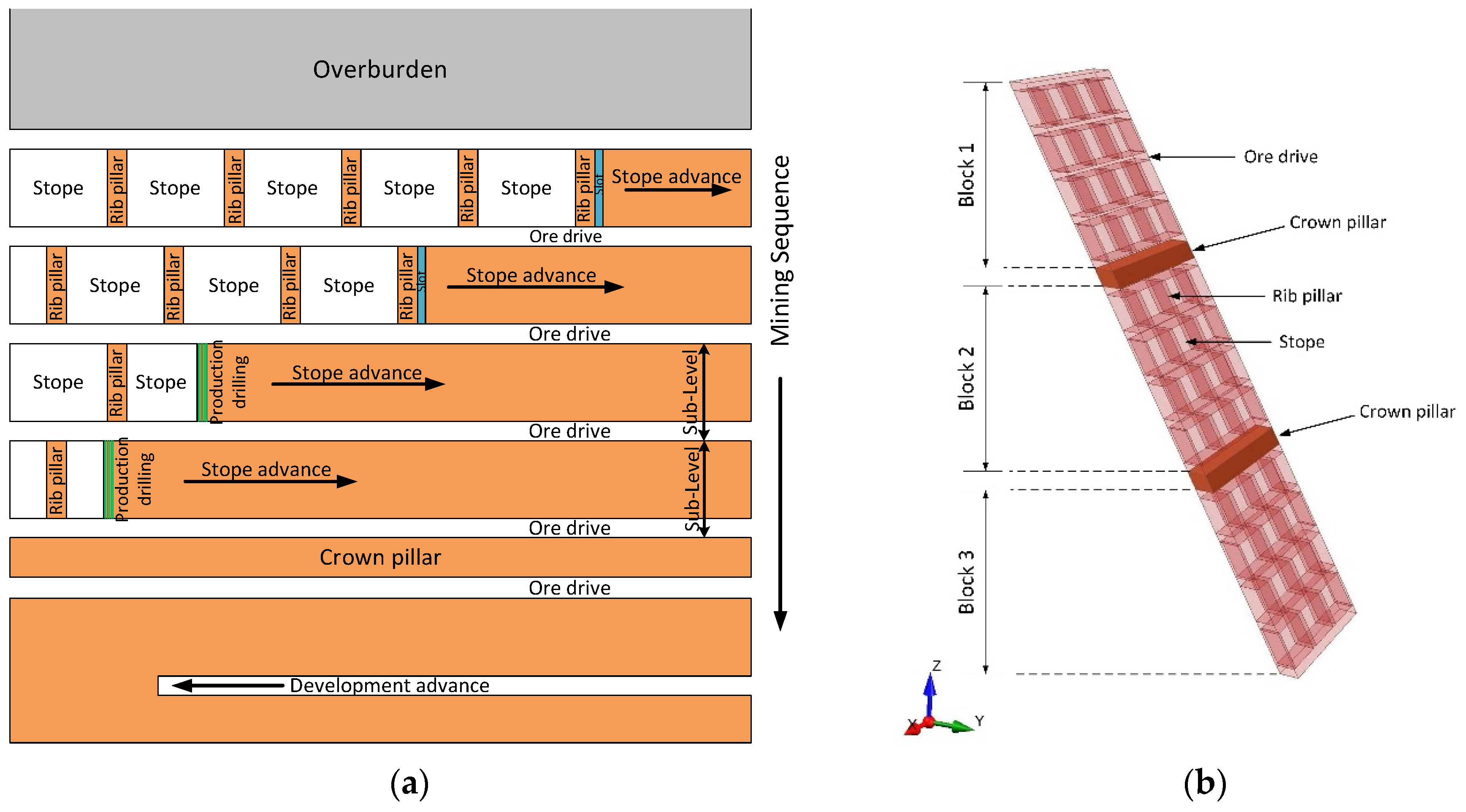
3.1. Description
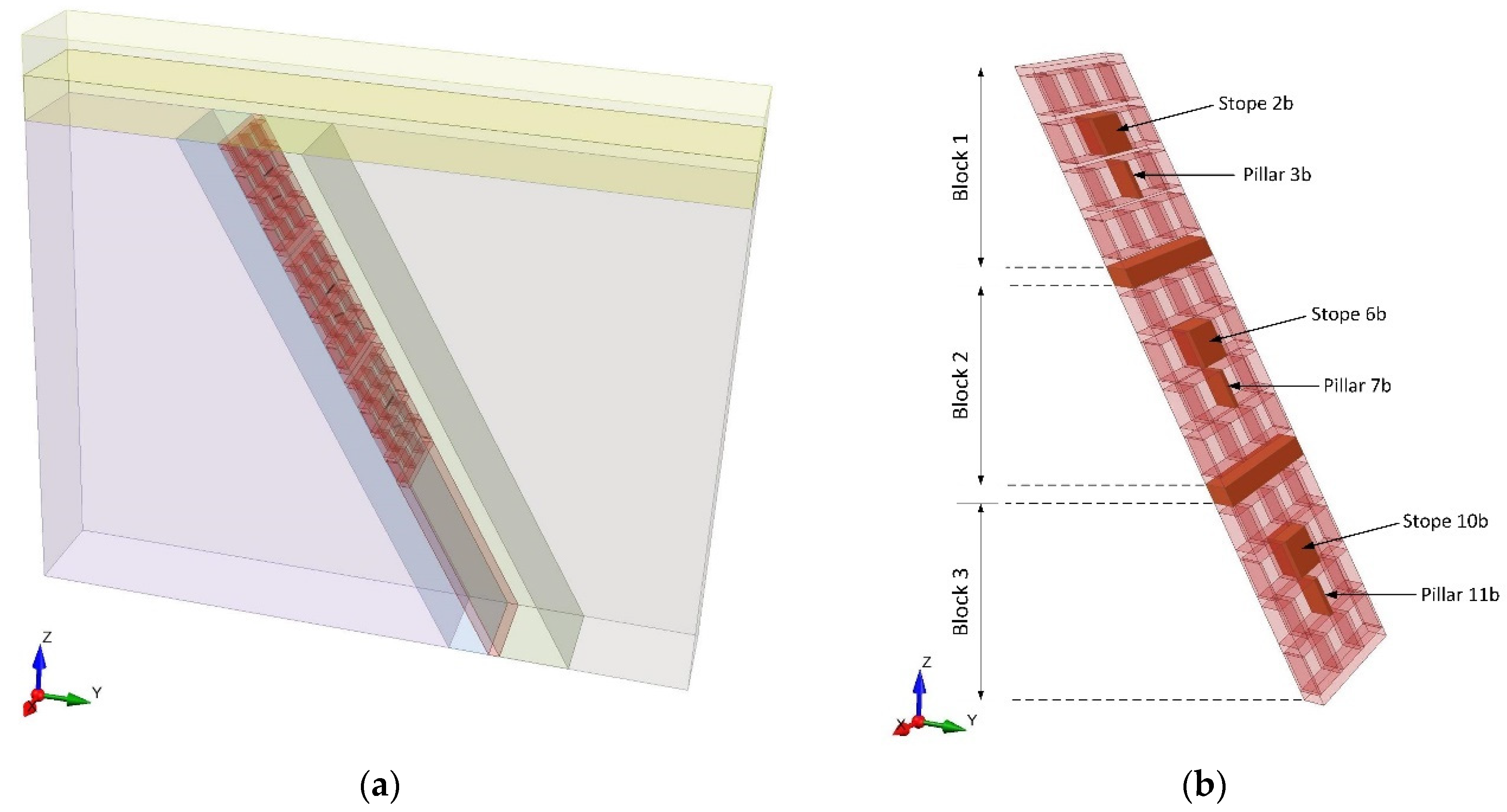
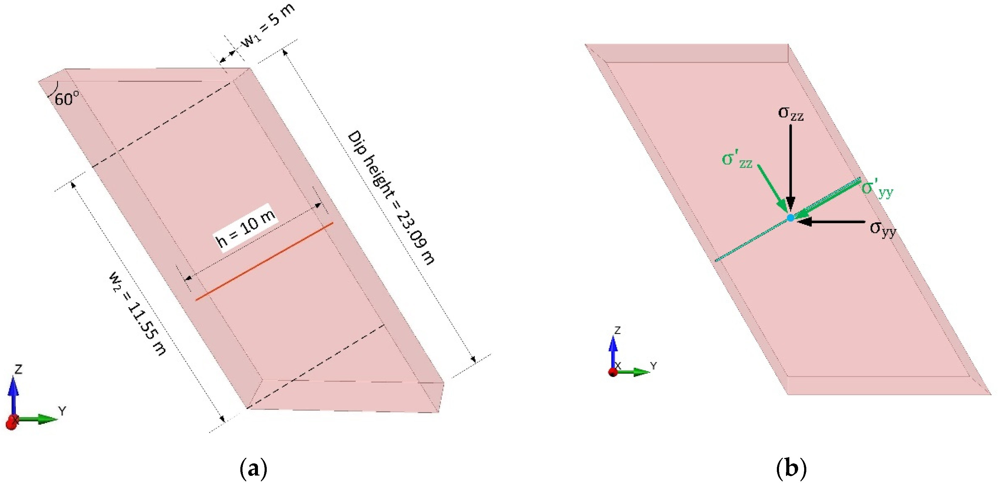
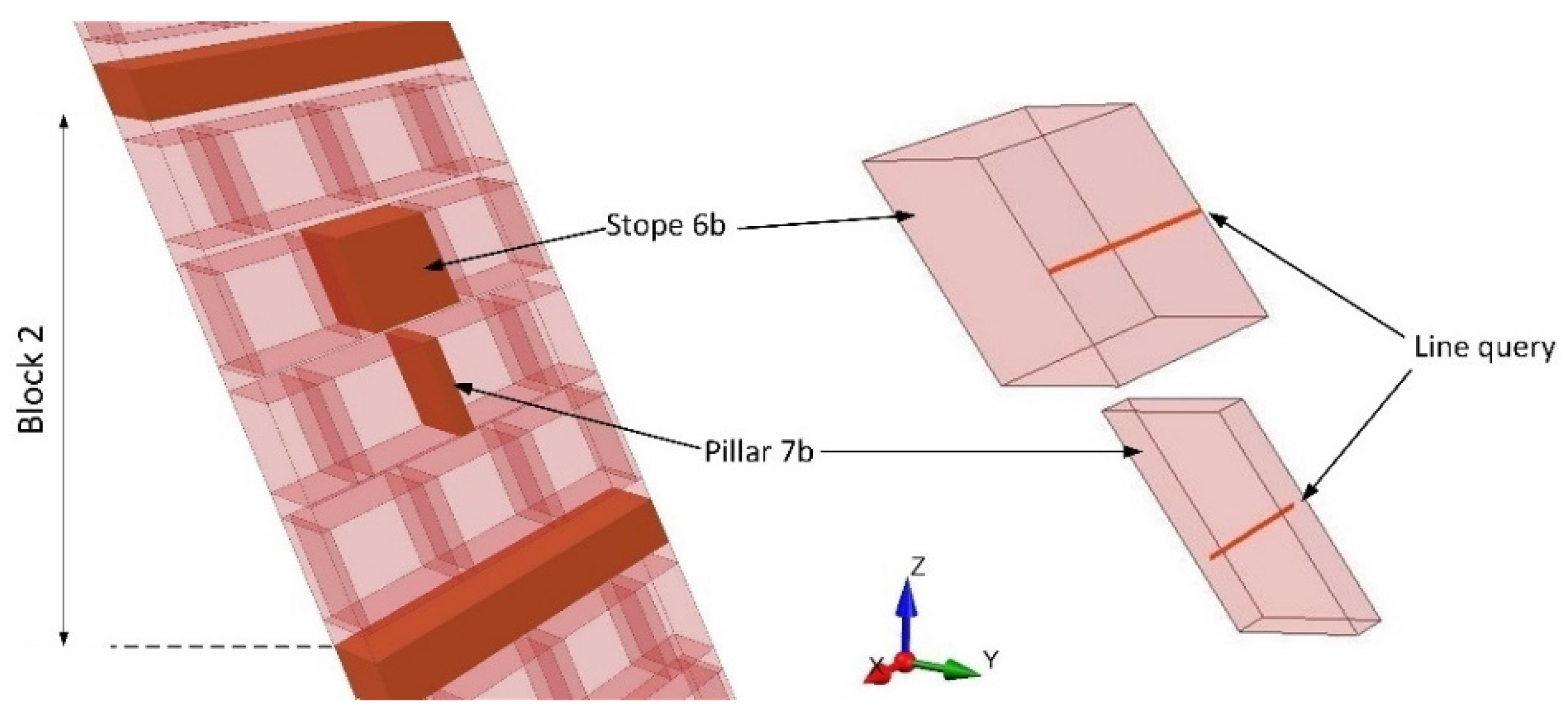
3.2. Numerical Modeling
4. Pillar Design Background
5. Results and Discussion
5.1. Stope Deformability
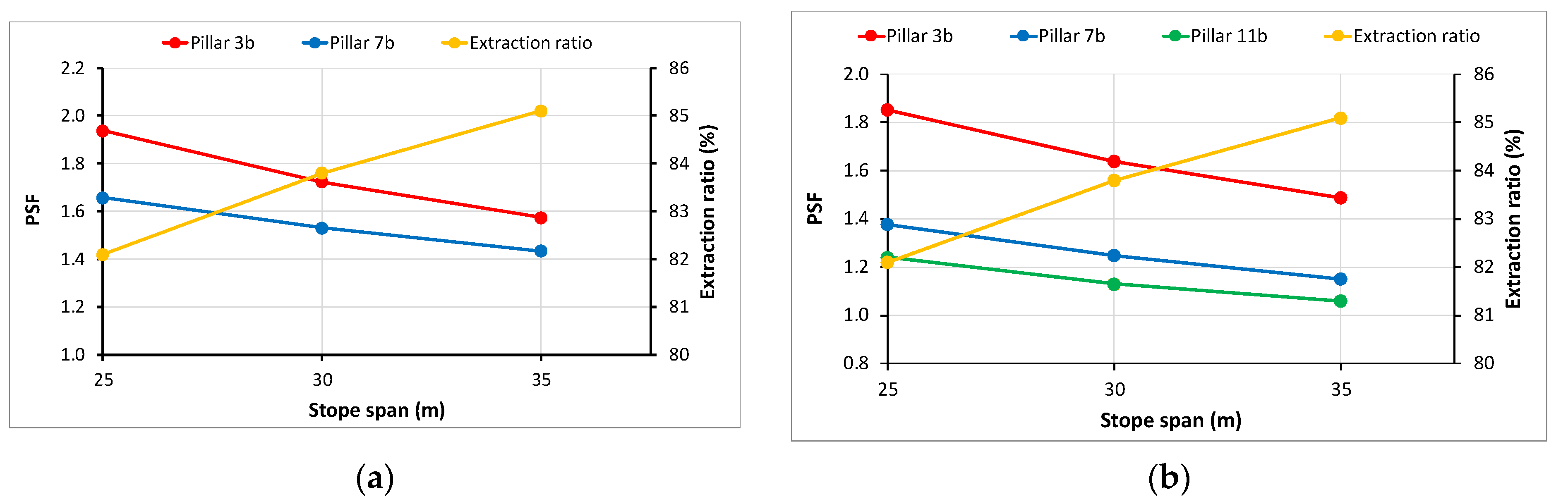
5.2. Rib Pillar Behavior and Stability
6. Conclusions
Institutional Review Board Statement
Informed Consent Statement
Data Availability Statement
Conflicts of Interest
References
- Brady, B.H.G.; Brown, E.T. Pillar supported mining methods. In Rock Mechanics for Underground Mining; Springer: Berlin/Heidelberg, Germany, 2004; pp. 370–407. [Google Scholar]
- Haycocks, C.; Aelick, R.C. Sublevel Stoping. In SME Mining Engineering Handbook; Hartman, H.L., Ed.; Society for Mining, Metallurgy and Exploration, Inc.: Englewood, CO, USA, 1992; Volume 2, pp. 1717–1731. [Google Scholar]
- Tatiya, R.R. Surface and Underground Excavations—Methods, Techniques and Equipment; A.A. Balkema Publishers: Leiden, The Netherlands; New York, NY, USA; Philadelphia, PA, USA; Singapore, 2005; pp. 415–437. [Google Scholar]
- Pakalnis, T.R.; Hughes, P.B. Sublevel Stoping. In SME Mining Engineering Handbook, 3rd ed.; Darling, P., Ed.; Society for Mining, Metallurgy and Exploration, Inc.: Englewood, CO, USA, 2011; pp. 1355–1364. [Google Scholar]
- Villaescusa, E. Geotechnical Design for Sublevel Open Stoping; CRC Press, Taylor and Francis Group: Boca Raton, FL, USA; London, UK; New York, NY, USA, 2014. [Google Scholar]
- Kumar, H.; Deb, D.; Chakravarty, D. Design of crown pillar thickness using finite element method and multivariate regression analysis. Int. J. Min. Sci. Technol. 2017, 27, 955–964. [Google Scholar] [CrossRef]
- Himanshu, V.K.; Tiwari, S.; Kushwaha, A.; Bhattacharjee, R. Elasto-plastic failure analysis for design of stoping dimension in underground metalliferous mine. NexGen Technol. Min. Fuel Ind. 2017, 1, 639–646. [Google Scholar]
- Mallı, T.; Yetkin, M.E.; Özfırat, M.K.; Kahraman, B. Numerical analysis of underground space and pillar design in metalliferous mine. J. Afr. Earth Sci. 2017, 134, 365–372. [Google Scholar] [CrossRef]
- Dzimunya, N.; Radhe, K.; William, C.M. Design and dimensioning of sublevel stoping for extraction of thin ore (<12 m) at very deep level: A case study of Konkola copper mines (kcm), Zambia. Math. Model. Eng. Probl. 2018, 5, 27–32. [Google Scholar] [CrossRef]
- Esterhuizen, G.S.; Dolinar, R.D.; Ellenberger, J.L.; Prosser, L.J. Pillar and Roof Span Design Guidelines for Underground Stone Mines; NIOSH, IC 9526: Pittsburgh, PA, USA, 2011. [Google Scholar]
- Esterhuizen, G.S.; Iannacchione, A.T. Effect of the Dip and Excavation Orientation on Roof Stability in Moderately Dipping Stone Mine Workings. In Proceedings of the 40th U.S. Symposium on Rock Mechanics (USRMS), Anchorage, AK, USA, 25–29 June 2005. [Google Scholar]
- Stanistreet, I.G.; Kukla, P.A.; Henry, G. Sedimentary basinal responses to a Late Precambrian Wilson Cycle: The Damara Orogen and Nama Foreland, Namibia. J. Afr. Earth Sci. 1991, 13, 141–156. [Google Scholar] [CrossRef]
- Kampunzu, A.B.; Armstrong, R.A.; Modisi, M.P.; Mapeo, R.B.M. Ion microprobe U-Pb ages on detrital zircon grains from the Ghanzi Group: Implications for the identification of a Kibaran-age crust in northwest Botswana. J. Afr. Earth Sci. 2000, 30, 579–587. [Google Scholar] [CrossRef]
- Carney, J.N.; Aldiss, D.T.; Lock, N.P. The Geology of Botswana, Geological Survey Department. Repub. Botsw. Bull. 1994, 37, 71–83. [Google Scholar]
- Modie, B.N. Geology and mineralisation in the Meso- to Neoproterozoic Ghanzi Chobe Belt of northwest Botswana. J. Afr. Earth Sci. 2000, 30, 467–474. [Google Scholar] [CrossRef]
- Modie, B.N.J. Depositional environments of the Meso- to Neoproterozoic Ghanzi-Chobe belt, northwest Botswana. J. Afr. Earth Sci. 1996, 22, 255–268. [Google Scholar] [CrossRef]
- Kelepile, T.; Bineli Betsi, T.; Franchi, F.; Shemang, E. Partitioning and distribution of silver in sediment-hosted Cu-Ag deposits: Evidence from the Ghanzi-Chobe Belt portion of the Kalahari Copper Belt. Ore Geol. Rev. 2020, 124, 103663. [Google Scholar] [CrossRef]
- Von Kimmelmann, M.R.; Hyde, B.; Madgwick, R.J. The use of computer applications at BCL Limited in planning pillar extraction and design of mining layouts. In ISRM Symposium: Design and Performance of Underground Excavations; Brown, E.T., Hudson, J.A., Eds.; British Geotechnical Society: London, UK, 1984; pp. 53–63. [Google Scholar]
- Krauland, N.; Soder, P.E. Determining pillar strength from pillar failure observations. Eng. Min. J. 1987, 188, 34–40. [Google Scholar]
- Potvin, Y.; Hudyma, M.R.; Miller, H.D.S. Design guidelines for open stope support. Can. Min. Metall. Bull. 1989, 82, 53–62. [Google Scholar]
- Sjoberg, J. Failure modes and pillar behaviour in the Zinkgruvan mine. In The 33rd U.S. Rock Mechanics Symposium, Sante Fe; Tillerson, J.A., Wawersik, W.R., Eds.; A.A. Balkema: Rotterdam, The Netherlands, 1992; pp. 491–500. [Google Scholar]
- Martin, C.D.; Maybee, W.G. The strength of hard-rock pillars. Int. J. Rock Mech. Min. Sci. 2000, 37, 1239–1246. [Google Scholar] [CrossRef]
- Lunder, P.J.; Pakalnis, R. Determination of the strength of hard-rock mine pillars. Can. Min. Metall. Bull. 1997, 90, 51–55. [Google Scholar]


| Stope Span | Pillar 3b | Pillar 7b | Pillar 11b | ||||
|---|---|---|---|---|---|---|---|
| (m) | PSF | PSF | PSF | ||||
| Block 1 | 25 | 13.78 | 2.54 | 3.09 | 11.28 | 4.17 | 8.38 |
| 30 | 15.10 | 2.31 | 3.10 | 11.27 | 4.17 | 8.38 | |
| 35 | 16.22 | 2.15 | 3.10 | 11.27 | 4.17 | 8.38 | |
| Block 2 | 25 | 18.04 | 1.94 | 21.08 | 1.66 | 4.32 | 8.09 |
| 30 | 20.28 | 1.72 | 22.82 | 1.53 | 4.34 | 8.05 | |
| 35 | 22.21 | 1.57 | 24.37 | 1.43 | 4.34 | 8.05 | |
| Block 3 | 25 | 18.85 | 1.85 | 25.36 | 1.38 | 28.23 | 1.24 |
| 30 | 21.32 | 1.64 | 27.98 | 1.25 | 30.86 | 1.13 | |
| 35 | 23.48 | 1.49 | 30.37 | 1.15 | 32.83 | 1.06 | |
Publisher’s Note: MDPI stays neutral with regard to jurisdictional claims in published maps and institutional affiliations. |
© 2021 by the authors. Licensee MDPI, Basel, Switzerland. This article is an open access article distributed under the terms and conditions of the Creative Commons Attribution (CC BY) license (https://creativecommons.org/licenses/by/4.0/).
Share and Cite
Kaklis, K.; Agioutantis, Z.; Masialeti, M.; Yendaw, J.; Betsi, T.B. Parametric Analysis of Rib Pillar Stability in a Longitudinal Sublevel Open Stoping Operation in an Underground Copper Mine in Southern Africa. Mater. Proc. 2021, 5, 11. https://0-doi-org.brum.beds.ac.uk/10.3390/materproc2021005011
Kaklis K, Agioutantis Z, Masialeti M, Yendaw J, Betsi TB. Parametric Analysis of Rib Pillar Stability in a Longitudinal Sublevel Open Stoping Operation in an Underground Copper Mine in Southern Africa. Materials Proceedings. 2021; 5(1):11. https://0-doi-org.brum.beds.ac.uk/10.3390/materproc2021005011
Chicago/Turabian StyleKaklis, Kostas, Zach Agioutantis, Munyindei Masialeti, Jerome Yendaw, and Thierry Bineli Betsi. 2021. "Parametric Analysis of Rib Pillar Stability in a Longitudinal Sublevel Open Stoping Operation in an Underground Copper Mine in Southern Africa" Materials Proceedings 5, no. 1: 11. https://0-doi-org.brum.beds.ac.uk/10.3390/materproc2021005011