
Upgrading of a Tailings Management Facility for the Disposal of Dry Stack Tailings †

1
Hellas Gold S.A., 23A Vas. Sofias Ave., GR-10674 Athens, Greece
2
Hellas Gold S.A., Stratoni, GR-63074 Halkidiki, Greece
*
Author to whom correspondence should be addressed.
†
Presented at International Conference on Raw Materials and Circular Economy, Athens, Greece, 5–9 September 2021.
Mater. Proc. 2021, 5(1), 132; https://0-doi-org.brum.beds.ac.uk/10.3390/materproc2021005132
Published: 6 June 2022
(This article belongs to the Proceedings of International Conference on Raw Materials and Circular Economy)
Abstract
:In every mine in the world, the result of the process is a slurry material called tailings. Today, more than ever before, the mining industry is looking for technical solutions to dewater mine tailings to eliminate the risk of tailings dam failures. In the Kassandra Mines in NE Chalkidiki, the Kokkinolakas Tailings Management Facility (KTMF) is currently in operation as a “dry stack” disposal area, by incorporating materials generated from the removal, cleaning, and rehabilitation of every old, non-operating tailings area from the extended past mining activities (1960–1995) as well as the tailings and wastes produced from the operations of the Olympias and Stratoni mines. Recently, the Kassandra Mines was also permitted to use the same dry stack technology at the Skouries project, providing the huge benefit for the environment of the full release of the Lotsaniko valley.
1. Introduction
Among other modern methods of tailings dewatering, the removal of excess water with the use of filter presses prior to the placement results in a soil-like or “wet cake” material (solid content by weight >80%) called dry stack tailings. These filtered tailings are normally transported by conveyor or truck, deposited, spread, and compacted.
The “dry stacking” tailings methodology is beneficial for the environment due to the less disturbed footprint for the disposal area; it also increases the physical stability of the tailings’ disposal and thus the construction of retention embankments can be avoided, simplifying the overall water management and recovery and providing complete restoration opportunities due to the direct access on the tailings surface.
For the safe application of the dry stacking disposal methodology, upstream diversion systems, surface contour management, and detailed tailings geotechnical testing are required. As a result, this method has higher capital and operating costs.
The purpose of this paper is to highlight the key construction elements of the Hellas Gold S.A. Kokkinolakas TMF dry stack tailings disposal area in NE Chalkidiki and to analyze how this facility is currently environmentally and geotechnically monitored.
2. Methodology Approach
The Tailings Management Facility (TMF) is an integrated and protected dry stacking area. The term dry stacking area means that all materials to be deposited will be almost free of moisture (solid content by weight >80%) to reduce the volume of the deposited materials while significantly improving the quality of the deposition.
The project is located in the area of Stratoniki Municipal District, of the Aristotelis Municipality of north-eastern Chalkidiki, approximately 100 km to the east of Thessaloniki. It is part of the Madem Lakkos mining complex and is more specifically at the area of Kokkinolakas stream, adjacent to the existing tailings deposition facilities Chevalier and Karakoli.
According to the approval of the environmental terms of the Kassandra mines project in Chalkidiki (Joint Ministerial Decision Ref. No. 201745/2011), Kokkinolakas TMF belongs to the “Mavres Petres and Madem Lakkos facilities” sub-project.
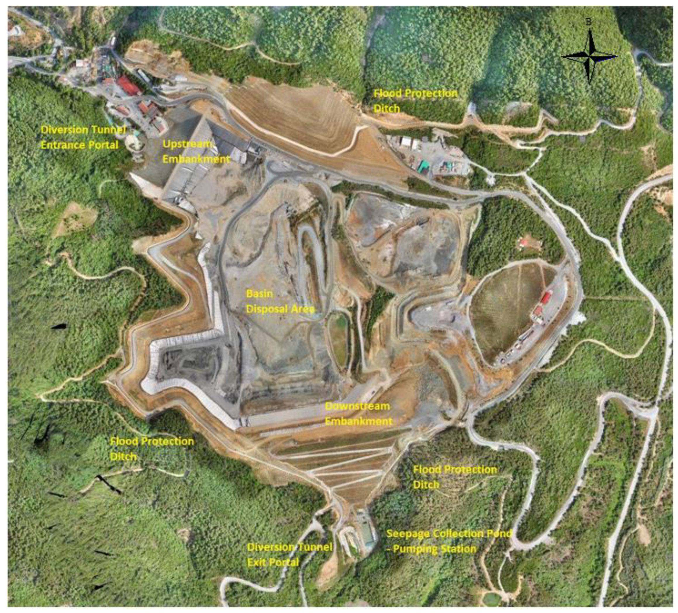
The TMF is designated to occupy Kokkinolakas’ upper-basin, covering an area of approximately 395,000 m2 after completion of the TMF, while the overall construction works cover an area of 475,000 m2 (Figure 1). As laid out and environmentally permitted, the TMF will operate for twenty (20) years as a dry stacking tailings facility, wherein “the tailings of current ore processing in conjunction with waste rock and a variety of past metallurgy wastes are deposited under environmentally confined conditions”. Actually, it is laid out as a waste landfill for hazardous industrial wastes. To meet the storage needs throughout the operation of the facility, the required total tailings storage capacity of Kokkinolakas TMF is adjusted to approximately 10.50 Mm3.
The Kokkinolakas TMF is designed to facilitate the deposition of recent as well as older wastes of the mining activity of the Madem Lakkos and the Olympias mines, notably the tailings currently produced from the operational underground mines of the Olympias and Mavres Petres mines which cannot be reused, recycled, or commercially exploited; and the materials which are to be derived from works of the removal, clearing, and rehabilitation of all old, non-operational tailings areas, which have built up from extended mining activities in the past in the wider area of Olympias, Mavres Petres—Madem Lakkos and Stratoni sub-projects—which cannot be reused, recycled, or commercially exploited.
3. Description of the Upgrading Workings
For the development and proper operation of the facility, the following main key components were examined within the frame of the Geotechnical Design [1] of the project:
- ➢
- The Kokkinolakas creek diversion tunnel to act as the bottom outlet in cases of extreme rainfall events;
- ➢
- The upstream central clay core rockfill embankment to act as a diversion dam to the flow of Kokkinolakas stream into the constructed and operational diversion tunnel;
- ➢
- The downstream rockfill embankment laid out to facilitate long-term buttressing requirements to the existing Karakoli embankment;
- ➢
- The hydraulic diversion structures for management (interception and discharge) of the surface runoff, around the perimeter of the TMF;
- ➢
- The borrow pit at the right abutment of the creek;
- ➢
- The formation of the basin to facilitate combined requirements for tailings transportation, installation, and anchoring of the composite liner. Due to the nature of the tailings and other waste materials to be deposited within the TMF, a composite lining system is installed at the entire surface of the deposition area, in order to meet the environmental design criteria for seepage and leachates handling;
- ➢
- The basal drainage system, which comprises two individual networks of semi-perforated HDPE pipes to run below (under-drainage system for non-contaminated/contact, groundwater seepage) as well as above the basal liner (over-drainage system for the leachates collection—noncontact water);
- ➢
- The two Chevalier ponds and the Karakoli facility at the SE of the TMF footprint; significant reclamation is designed for the existing and old tailings facilities of Chevalier ponds towards safe incorporation into the major TMF scheme, while safeguarding of the Karakoli (outside of the TMF boundary) facility is foreseen;
- ➢
- The handling of the geotechnical/environmental hazards linked with the mine adit +173 which is implicated with the basin;
- ➢
- The seepage collection pond downstream of Kokkinolakas TMF.
- 3a. Technical-civil engineering workings
- 3a.1 The Kokkinolakas creek diversion tunnel
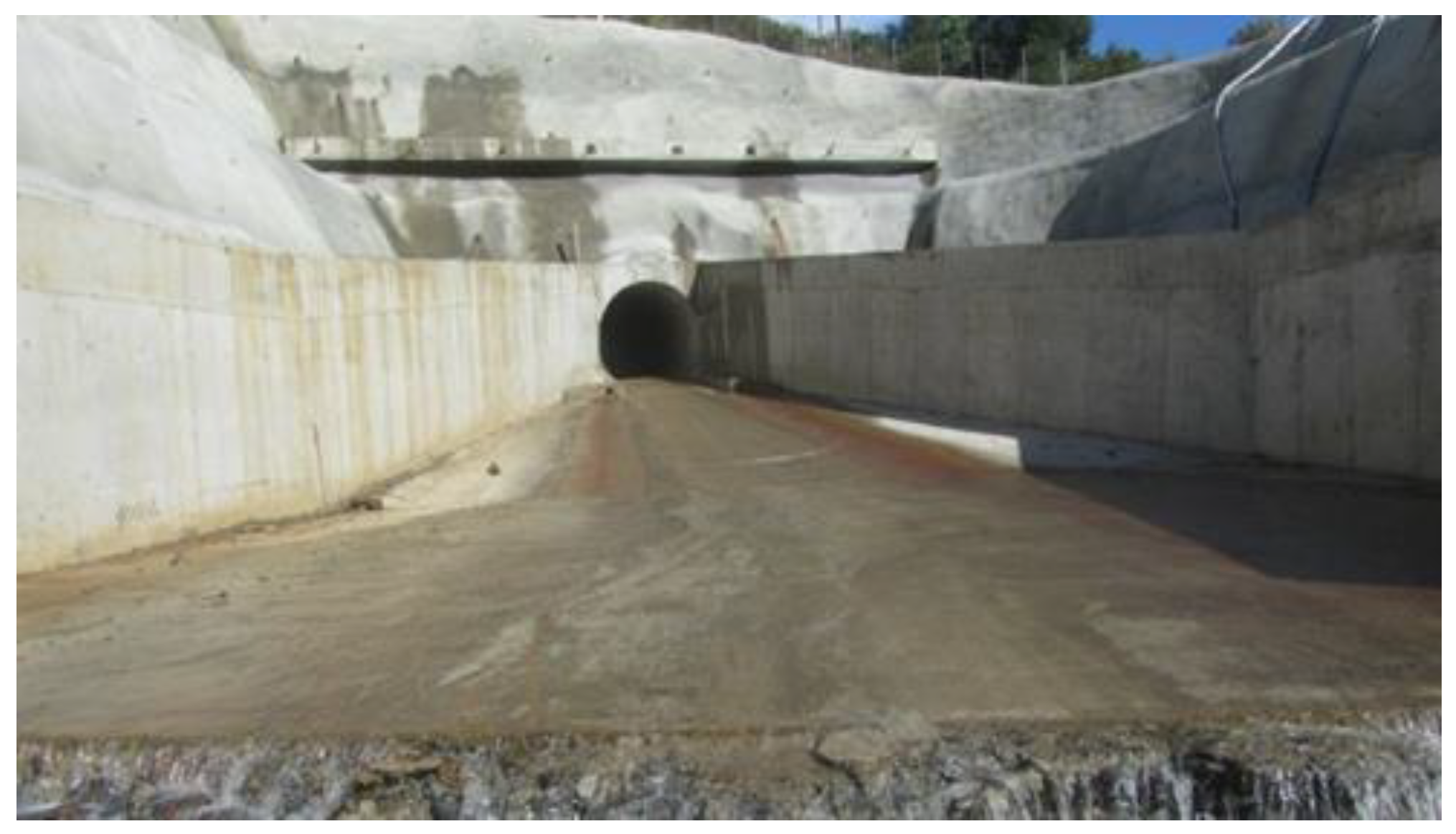
The purpose of this diversion tunnel is to divert the flow of Kokkinolakas creek outside the tailings storage facility to meet again with the natural receiver (Kokkinolakas creek) downstream of the D/S embankment.
The diversion tunnel has a length of 1050 m, is 100% concrete lined, has a useful hydraulic cross section of 9.55 m2, and has been designed for a returning period of 200 years.
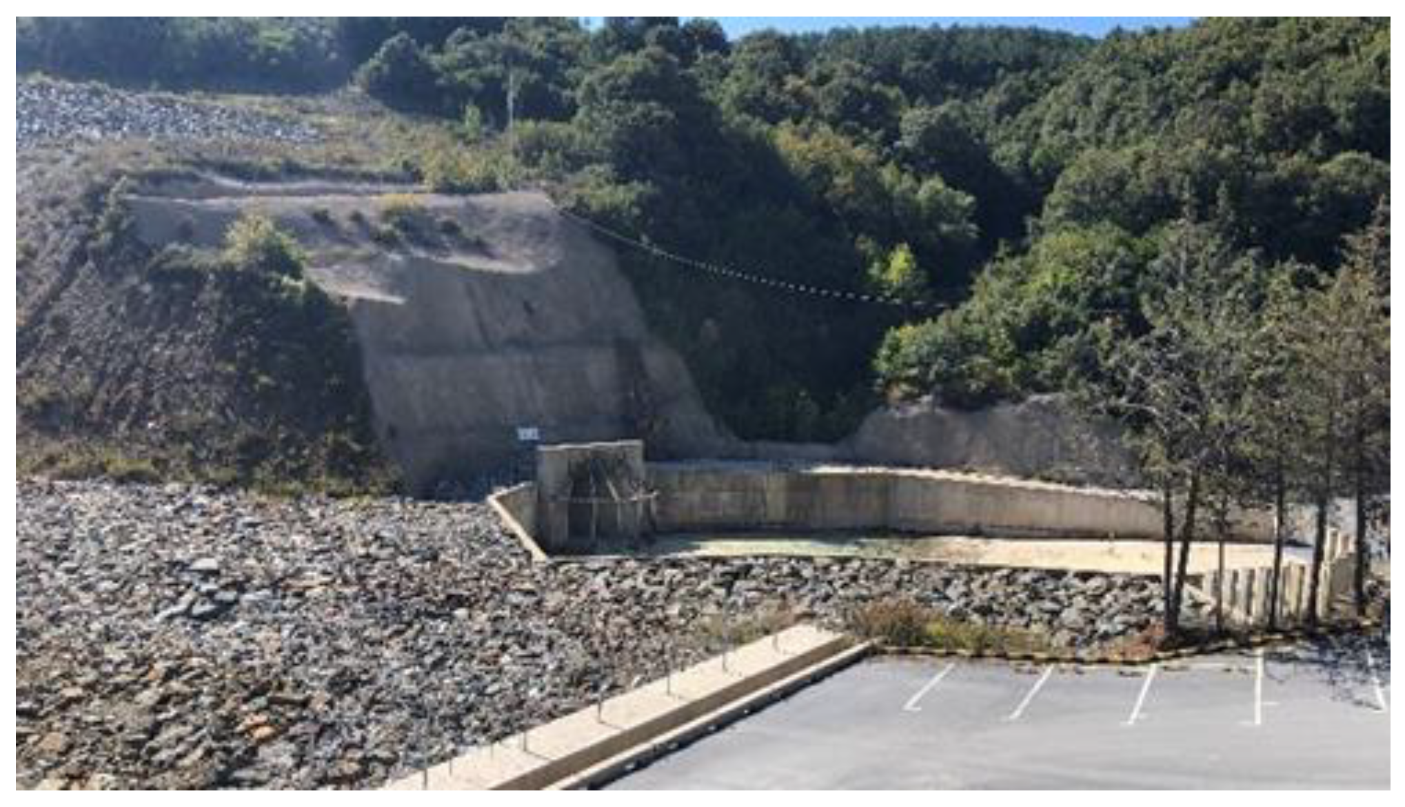
The diversion tunnel hydraulically cooperates with the upstream (U/S) embankment (Figure 2), which is constructed with an impermeable clay core, so that in cases of extreme rainfall events the upstream flood can be retained at the U/S embankment upstream slope and discharged through the diversion tunnel which is acting as the bottom outlet. The exit portal of the tunnel is located downstream of the D/S embankment footprint (Figure 3).
- 3a.2 The surface contour water management
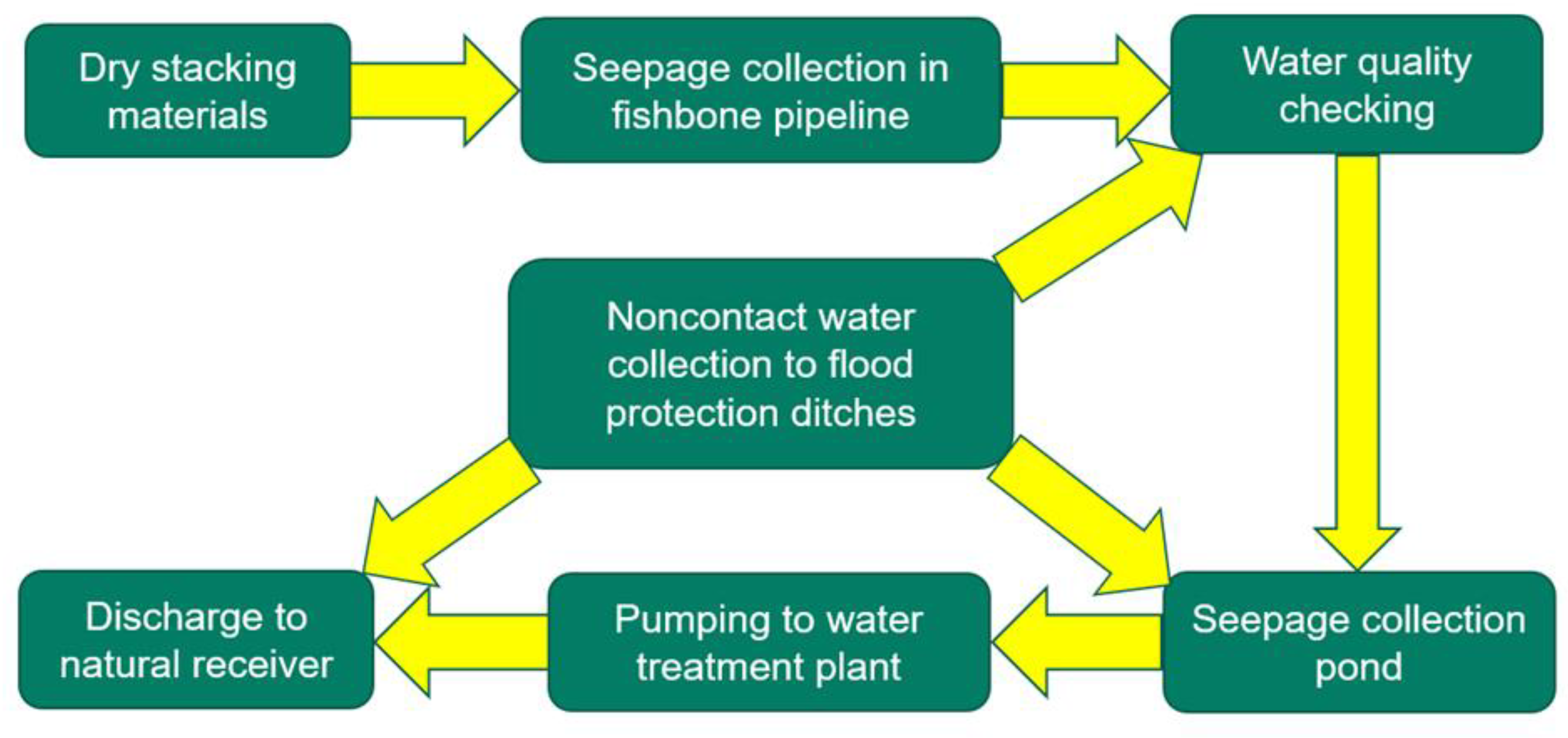
The contour water management (Figure 4) is performed through three perimetric flood protection ditches of a total length of 4.35 km at the final elevation of the facility.
In the left abutment, two flood protection ditches have been constructed, one for non-contact and one for contact water, while along the right abutment one flood protection ditch of non-contact water has been constructed.
All ditches have been designed for a returning period of 100 years.
The non-contact water ditches’ discharge point is the natural receiver (Kokkinolakas creek), while the contact water ditch is discharged directly to the seepage collection pond. In cases of extreme rainfall events, 90% of the contact water ditch is automatically diverted inside the TMF basin to create a buffer reservoir.
- 3a.3 The composite lining system
The engineering of the KTMF lining system is in accordance with the following regulations/legislation:
- ➢
- The provisions of the Joint Ministerial Decision 39624/2209/E103/2009, in compliance with the European Committee Directive 2006/21/EC;
- ➢
- The “Reference Document on Best Available Techniques for Management of Tailings and Waste-Rock in Mining Activities”;
- ➢
- The provisions of the Joint Ministerial Decision 24944/1159/2006 (GGG 791/B/2006), for Technical Specifications in hazardous waste disposal facilities.
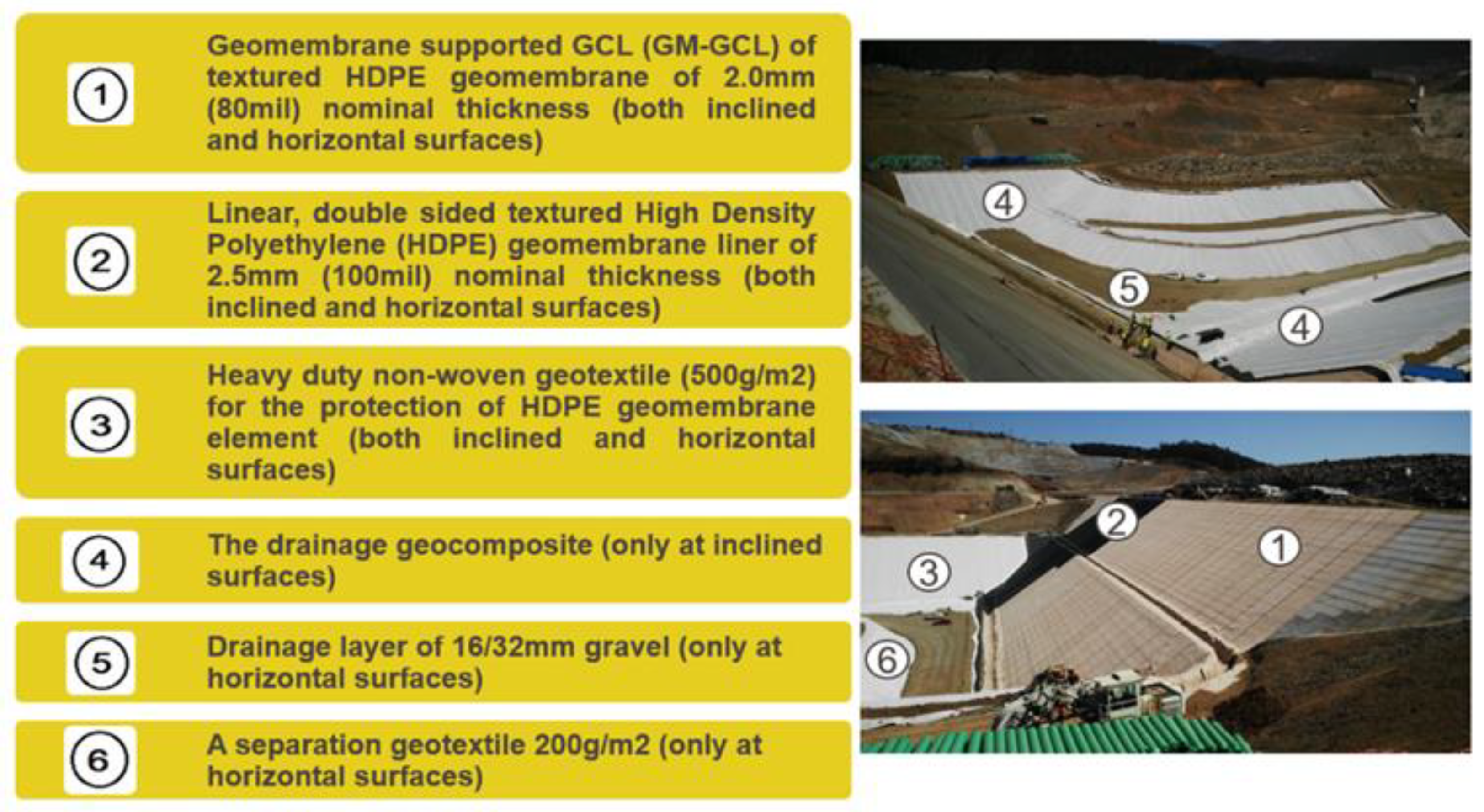
The different layers of the composite liner system (Figure 5) from the bottom to the top are as follows:
The impermeable barrier consisted of the following:
- The geosynthetic clay liner (GCL), with a nominal hydraulic conductivity ≤4 × 10⁻¹⁴ m/s and a thickness of 2.0 mm (80 mil). The general application mode that is preferred for the geomembrane (GM)-GCL rolls regards the high-density polyethylene (HDPE) membrane faced down. The hydraulic conductivity of the GM-GCL was calculated by an independent scientific committee [2] as being equivalent to a 700 m thick compacted natural clay layer and consequently the geosynthetic clay barrier was judged as 140 times more effective than that suggested from the legislation (5 m compacted natural clay layer);
- The double-sided textured HDPE geomembrane liner is 2.5 mm (100 mil) in thickness. The requirement of the application of a double-sided textured geomembrane is set for all the sloping surfaces of the basin apart from the nearly horizontal (gradients < 2%), where the application of a smooth product can be adopted.
The leachate drainage and collection layer consisted of the following:
- The heavy duty, polypropylene, non-woven geotextile of 500 g/m2 which aims to protect the geomembrane against puncture;
- The drainage geo-composite, manufactured by thermo-bonding a draining core HDPE geogrid with one non-woven geotextile performing as a separation, filtration, and protection layer.
The drainage geo-composite is applied to all the sloping surfaces, apart from the nearly horizontal areas of the basin (gradients < 2%), wherein the geo-composite is substituted by a sufficiently thick layer (50 cm at minimum) of drainage material (sandy gravel 16/32 mm) capped by a separation geotextile of 200 g/m2 for separation from the fine tailings.
- 3a.4 The Upstream Embankment
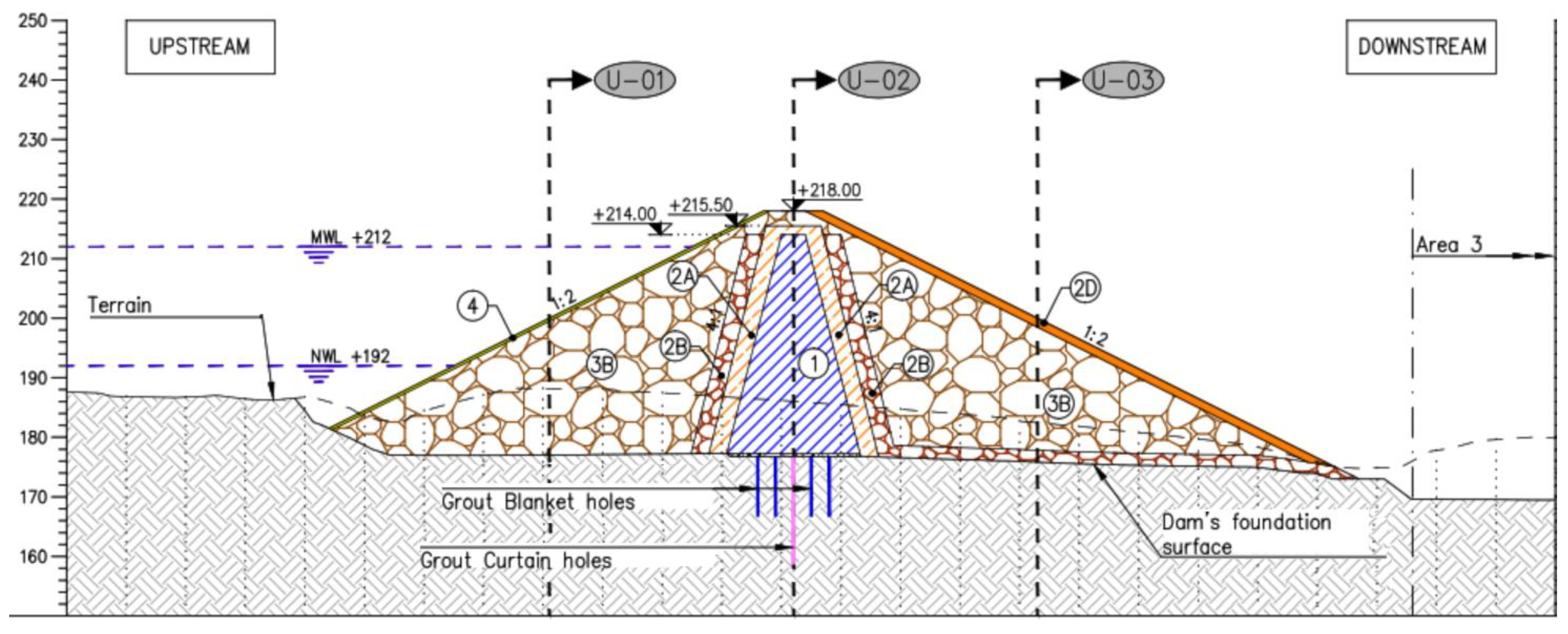
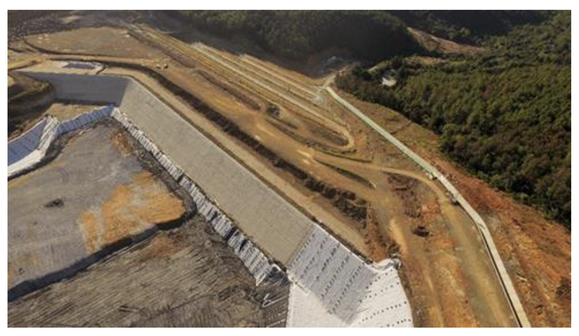
The upstream embankment (Figure 6 and Figure 7) is located at the north-western edge of Kokkinolakas basin and is designed as central clay core rockfill dam to retain storm waters in the upstream of the TMF (Figure 6).
The construction method was by axial raising, with the final raise being reached at one stage—the crest height is 40 m and the materials volume is 0.5 Mm³ g.
Affiliated works related with the U/S embankment construction were the entrance portal of the diversion tunnel, the Madem Lakkos offices pile walls, the +173 adit concrete slab/plug, the footprint excavations, the blanket-curtain grouting, the reinforced plinth in both abutments, the extruded curb, and the lining of the downstream slope.
The zonation of the U/S embankment from upstream to downstream consists of riprap, shells/rockfill, a coarse filter, a fine filter, an impermeable core, a fine filter, a coarse filter, shells/rockfill, and a liner bedding layer.
- 3a.5 The Downstream Embankment
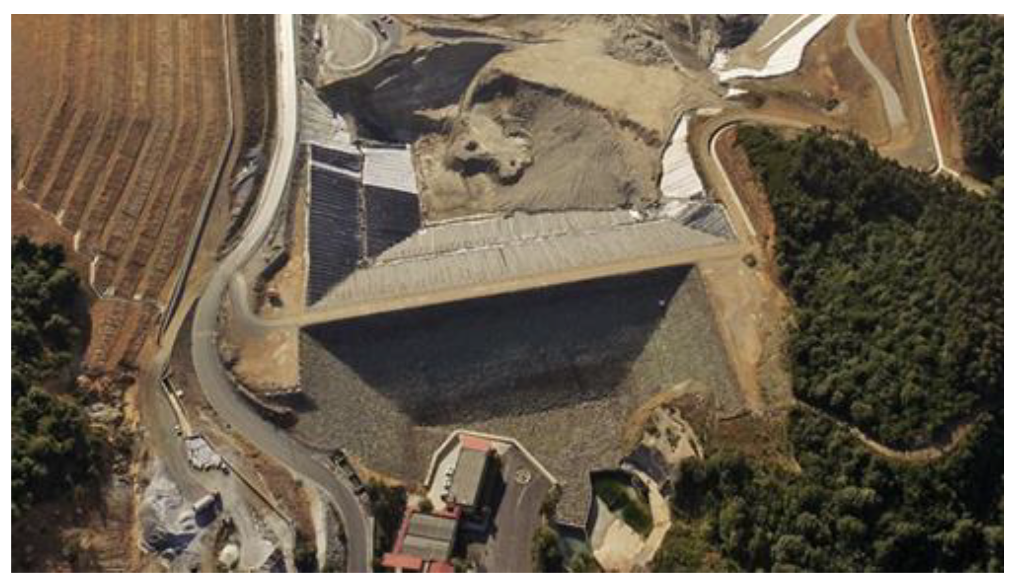
The downstream embankment (Figure 8 and Figure 9) is located at the southern part of Kokkinolakas basin and is designed as a free draining rockfill embankment.
The construction method was by “hybrid” axial–downstream raising; the final raise was reached at four stages, the crest height is 80 m, and the materials volume is 2.6 Mm³.
Affiliated works related with the D/S embankment construction were the footprint excavations, the overdrainage (ODR)/underdrainage (UDR) pipelines, the upstream slope extruded curb and lining, the downstream slope topsoil and hydroseeding, the service road, the cut-off shaft, the monitoring shaft, the seepage collection pond, and the pumping station.
The zonation of the D/S embankment from upstream to downstream consists of a liner bedding layer, a rockfill- transition zone, and rockfill.
- 3b. Environmental monitoring
The environmental monitoring of Kokkinolakas TMF is conducted by using the following groups of measuring devices/instruments:
3b.1 Lysimeters—Used to measure water leakages from the liner and the over-drainage system. Installed to determine the volume of water and chemicals draining from the vadose zone into groundwater. The measurement step is 15 days. If there is water, a sample is taken every 15 days.
3b.2 Monitoring wells—Used to measure the groundwater regime below and around the TMF. Check the composition of the groundwater and the level of the aquifer. The measurement step is 5 min. A water sample is taken every 15 days.
3b.3 Earth pressure cells—Used to measure the groundwater, earth, and total pressures in and around the earth structures. Installed in a trench in the embankment body. They record the pressure by the overlying earth and are connected to vibrating wire sensors which measure the pressure of the oil.
3b.4 Vibrating wire piezometers in boreholes—Used to measure the water pressure of the pores and the groundwater level. Installed in boreholes in the foundation of the upstream and downstream embankment. The measurement step is 5 min.
3b.5 Quality and quantity of all streams’ flow—The quality and quantity of each stream seepage flow is continuously monitored by measuring the flow rate, pH, total suspended solids (TSS), and conductivity. These parameters are continuously measured in the monitoring sump located just before the seepage collection pond through automated measuring devices connected with the SCADA system. The ability to have continuous measurements of the flow rate of each stream in cases of extreme rainfall events is critical in order to evaluate the effectiveness of the preventing measures and decide on modifications as required from the climate change effect.
- 3c. Geotechnical monitoring
The geotechnical monitoring of Kokkinolakas TMF and more specifically the movements in the dam body, at the abutments, in critical sections, and affiliated facilities is made by using the following groups of measuring devices/instruments:
3c.1 Survey monuments—Used to measure the dam crest settlement. The measurement step is twice a week at the crest and dam body and twice a month for all the other points.
3c.2 Horizontal extensometers—Used to measure the horizontal displacements of the dam body. Installation is done in a ditch 60 cm deep in the body of the embankment. The measurement step is 5 min.
3c.3 Hydrostatic settlement cells—Used to measure the dam body settlement. The measurement step is 5 min.
3c.4 Vibrating wire piezometers in dam body—Used to measure the pores’ water pressure through a vibrating wire converter. The measurement step is 5 min.
3c.5 Settlement gauges within inclinometer tubes—Used to measure the sedimentation of the surrounding geomaterial. The measurement step is 15 days.
3c.6 Inclinometers—Used to measure the subsidence of the surrounding geomaterial. The measurement step is 5 min.
3c.7 Accelerometers—Used to measure the seismic response of the embankment walls and the ground acceleration caused in the case of strong dynamic oscillation–movement. The measurement and recording of the signal are continuous.
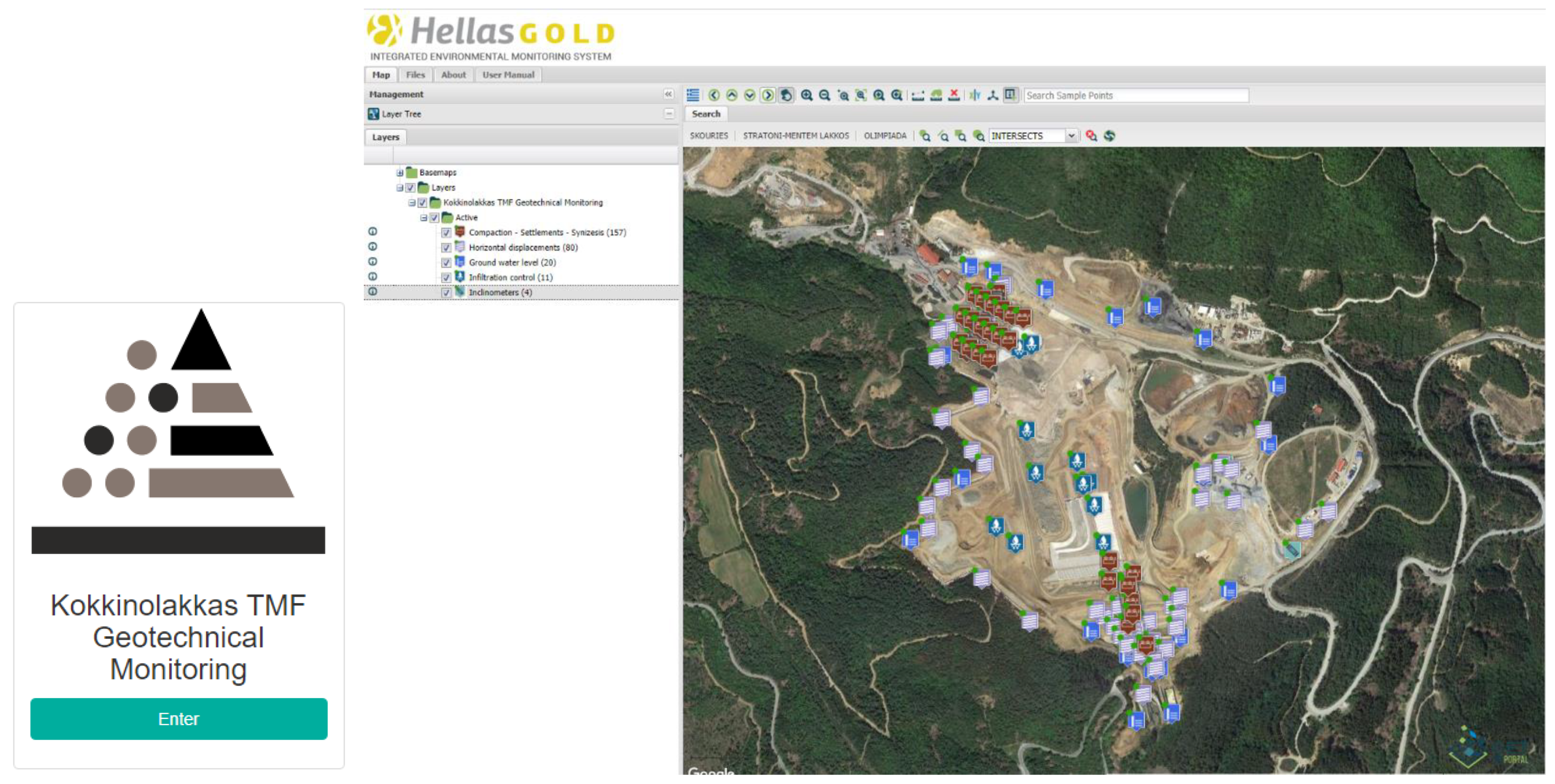
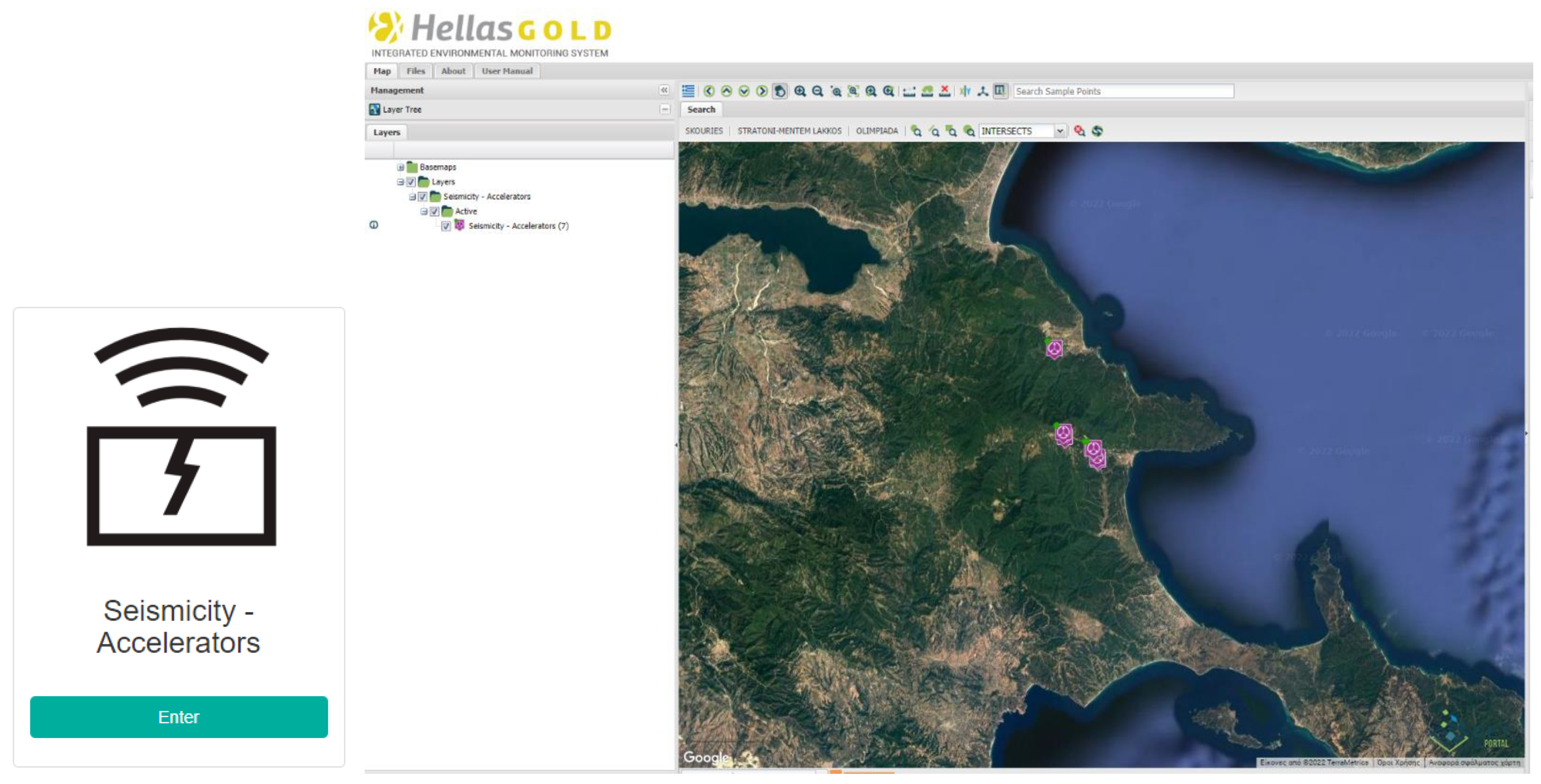
The measurements of the geotechnical and environmental monitoring of Kokkinolakas TMF are uploaded in real time to the Hellas Gold S.A. environmental monitoring database (Figure 10 and Figure 11), available online: https://environmental.hellas-gold.com/?lang=EN, accessed on 21 January 2022.
Furthermore, the measurements of the geotechnical and environmental monitoring of Kokkinolakas TMF are forwarded monthly to the Project Designer for evaluation and the deliverables are monthly, quarterly, and annual reports. The Project Designer reports are also uploaded to the Hellas Gold S.A. environmental monitoring database. According to all these reports, the geotechnical behavior of the Kokkinolakas TMF is so far characterized as “normal”.
4. Discussion
The main discussion related to the decision of implementing the dry stack tailings technology in a mine has to do with the advantages and disadvantages that the specific option is providing.
The major advantages of the dry stacking disposal methodology can be summarized as follows:
- Risks of catastrophic dam failure and tailings runout as associated with conventional storage facilities are eliminated.
- Groundwater contamination through seepage is virtually eliminated.
- Compared to other, higher density surface tailings storage options, the dry stack facilities have a smaller environmental footprint, and it is possible to achieve higher disposal raises.
- The rehabilitation of the dry stacking areas can be progressive, so that the overall environmental disturbance is mitigated, and the cost is spread across the life of the mine.
- Due to the high density of the disposed tailings, higher rates of raise can be achieved compared with conventional disposal methods, while the ability to be accessed by mechanical equipment for spreading and compacting in layers is beneficial for the geotechnical behavior of the facility.
- It can be used in areas where water conservation is critical, i.e., any water losses can jeopardize plant performance.
The major disadvantages of the dry stacking disposal methodology can be also summarized as follows:
- It has high capital and operating costs associated with modern filtration technology (filter presses) that render other tailings storage options more economic to develop.
- Upstream diversion systems are required to prevent flooding of the dry stack facility.
- Surface contour management is required to prevent the accumulation and to facilitate the easy removal of surface water in cases of extreme rainfall events to prevent erosion of the slopes and flooding of the facility basin.
- It is difficult to store water within a dry stack facility. A conventional tailings facility, designed to store water, can provide a mining operation with a buffer for storm water storage.
- Seasonal fluctuations are an important consideration in the design of a dry stack tailings facility. The dry stack installation in a high rainfall environment can create day-to-day management problems for the trafficability of haulage and compaction equipment.
- Dust generation is a common problem in arid climates and can occur relatively quickly after tailings disposal due to the low moisture content of the placed material.
5. Conclusions
It can be concluded from the discussion that a management decision of applying the dry stacking technology in mining operations cannot be taken for granted and has mainly to do with the specific country regulations/environment of each mining area. There are site conditions, including the regulatory regime, that make a tailings dry stack the best choice for certain projects.
There are also reasons to select dry stacked filtered tailings methodology as a management option where terrain/foundation conditions contraindicate conventional impoundments or where it is required to recover process water to not jeopardize the plant operation.
For the Kokkinolakas TMF facility, the decision to implement the specific dry stacking technology was mainly based on the Eldorado Gold/Hellas Gold S.A. vision, values, and policies regarding health and safety, the environment, and compliance with legislation and permitting terms.
The advantage of eliminating the risk of a catastrophic dam failure or tailings runout at the facility along with zero possibility of loss of life (as per the performed risk assessment) prevail over any other argument.
The advantages of reducing the environmental footprint, the elimination of groundwater contamination, and the potential of staged/progressive rehabilitation of the facility were also taken seriously into account.
Finally, the regulatory status as described in the permitting terms according to Greek/European Union norms and standards was fully respected. Kokkinolakas TMF was designed and constructed as an extractive wastes disposal area with the specifications of a hazardous wastes disposal area.
Author Contributions
E.Z. is the project manager of Kokkinolakas TMF and has the legal responsibility against all Greek state authorities for the operation and maintenance of the facility. He has prepared the initial document and he reviewed it following the comments made by the publisher; D.D. as CEO of Hellas Gold S.A. has encouraged the preparation of this document and supported its publishing potential; V.G. as Environmental Manager of Hellas Gold S.A. was contributed for highlighting the significance of this project towards the restoration and protection of the environment and specifically is managing the uploading of the environmental and geotechnical monitoring data to the Hellas Gold S.A. site in real time. All authors have read and agreed to the published version of the manuscript.
Funding
The research received no external funding.
Institutional Review Board Statement
Not applicable.
Informed Consent Statement
Not applicable.
Data Availability Statement
Not applicable.
Conflicts of Interest
The authors declare no conflict of interest.
References
- OmicronKappa Consulting, Hellas Gold S.A. Short Report on Detailed Design for Kokkinolakkas Tailings Management Facility (TMF) in Kassandra Mines Chalkidiki, Northern Greece, December 2015. Available online: https://omikronkappa.gr/wp-content/uploads/Mine_Kokkinolakkas_TMF.pdf (accessed on 5 September 2021).
- Voudouris, K.; Gerolymos, N.; Marinos, V.; Kazakis, N.; Stoubos, G.; Xalikakis, K. Kokkinolakas Dry Stack Disposal Area Scientific Committee Consultancy Services; Final Report; Aristoteles University: Thessaloniki, Greece, 2019. [Google Scholar]
Figure 1.
Kokkinolakas Tailings Management Facility plan view.

Figure 2.
Diversion tunnel entrance portal.

Figure 3.
Diversion tunnel exit portal.

Figure 4.
Kokkinolakas TMF water management flowchart.

Figure 5.
Description and installation of the composite lining system.

Figure 6.
Upstream embankment engineering.

Figure 7.
Upstream embankment construction.

Figure 8.
Downstream embankment engineering.

Figure 9.
Downstream embankment construction.

Figure 10.
Monitoring database main screen.

Figure 11.
Seismicity database main screen.

Disclaimer/Publisher’s Note: The statements, opinions and data contained in all publications are solely those of the individual author(s) and contributor(s) and not of MDPI and/or the editor(s). MDPI and/or the editor(s) disclaim responsibility for any injury to people or property resulting from any ideas, methods, instructions or products referred to in the content. |
© 2022 by the authors. Licensee MDPI, Basel, Switzerland. This article is an open access article distributed under the terms and conditions of the Creative Commons Attribution (CC BY) license (https://creativecommons.org/licenses/by/4.0/).
Share and Cite
MDPI and ACS Style
Dimitriadis, D.; Zachareas, E.; Gazea, V. Upgrading of a Tailings Management Facility for the Disposal of Dry Stack Tailings. Mater. Proc. 2021, 5, 132. https://0-doi-org.brum.beds.ac.uk/10.3390/materproc2021005132
AMA Style
Dimitriadis D, Zachareas E, Gazea V. Upgrading of a Tailings Management Facility for the Disposal of Dry Stack Tailings. Materials Proceedings. 2021; 5(1):132. https://0-doi-org.brum.beds.ac.uk/10.3390/materproc2021005132
Chicago/Turabian StyleDimitriadis, Dimitris, Efstratios Zachareas, and Vithleem Gazea. 2021. "Upgrading of a Tailings Management Facility for the Disposal of Dry Stack Tailings" Materials Proceedings 5, no. 1: 132. https://0-doi-org.brum.beds.ac.uk/10.3390/materproc2021005132