Article

Exploring the Feasibility and Performance of Perovskite/Antimony Selenide Four-Terminal Tandem Solar Cells

1
Department of Metallurgical and Materials Engineering, The University of Alabama, Tuscaloosa, AL 35487, USA
2
School for Engineering of Matter Transport and Energy, Arizona State University, Tempe, AZ 85287, USA
*
Author to whom correspondence should be addressed.
Submission received: 31 January 2024 / Revised: 14 March 2024 / Accepted: 29 March 2024 / Published: 3 April 2024

Abstract

:
The tandem solar cell presents a potential solution to surpass the Shockley–Queisser limit observed in single-junction solar cells. However, creating a tandem device that is both cost-effective and highly efficient poses a significant challenge. In this study, we present proof of concept for a four-terminal (4T) tandem solar cell utilizing a wide bandgap (1.6–1.8 eV) perovskite top cell and a narrow bandgap (1.2 eV) antimony selenide (Sb2Se3) bottom cell. Using a one-dimensional (1D) solar cell capacitance simulator (SCAPS), our calculations indicate the feasibility of this architecture, projecting a simulated device performance of 23% for the perovskite/Sb2Se3 4T tandem device. To validate this, we fabricated two wide bandgap semitransparent perovskite cells with bandgaps of 1.6 eV and 1.77 eV, respectively. These were then mechanically stacked with a narrow bandgap antimony selenide (1.2 eV) to create a tandem structure, resulting in experimental efficiencies exceeding 15%. The obtained results demonstrate promising device performance, showcasing the potential of combining perovskite top cells with the emerging, earth-abundant antimony selenide thin film solar technology to enhance overall device efficiency.

1. Introduction

Solar energy represents rich renewable energy on the Earth. Harvesting of solar energy by a single-junction solar cell for electricity generation is limited by the Shockley–Queisser limit (SQL) [1,2]. To overcome this theory bottleneck, forming a tandem solar cell architecture by combining a wide bandgap and a narrow bandgap subcell is an effective and affordable approach [3,4]. Traditionally, two types of tandem structures were widely developed: one is the monolithic two-terminal (2T) tandem solar cell and the other is the mechanical stacking of two subcells to form a four-terminal (4T) tandem solar cell [5]. Particularly, the 4T tandem solar cell has more freedom to utilize the subcells cost-effectively without considering the current matching in the 2T tandem solar cell. The top cell with a wide-bandgap (WBG) absorbs high-energy photons and allows the low-energy photons to be transmitted through and then absorbed by the narrow-band gap (NBG) bottom cell [6,7]. The suitable WBG top cells should have a bandgap from 1.6 to 1.9 eV, while the bottom solar cell is around 1.1 to 1.2 eV to maximize the overall power conversion efficiency (PCE) at greater than 40% [4]. So far, various tandem device has been proposed based on the available relatively mature solar cell technology. A theoretical efficiency of around 42% can be achieved for an ideal two-junction tandem solar cell [8]. An example is the multijunction InGaP/GaAs-based tandem device [9]. However, most of these tandem devices still have high costs and are difficult to scale up for manufacture. Particularly, in 2T tandem devices, the wide bandgap top and narrow bandgap bottom cells are connected by an interconnect layer (ICL) [10,11]. Ensuring efficient charge transport through the ICL and current alignment between the top and bottom cells are the key challenges to avoid extra power dissipation. In addition, the lattice and thermal expansion coefficient mismatch between dissimilar materials can lead to stress, strain and defects at the interface that affect the long-term stability. In contrast, in four-terminal designs, the top and bottom subcells are separated, allowing each device to be easily modified or replaced as needed. The 4T devices tend to be more stable due to their physical isolation, making them less prone to degradation compared to 2T structures [12,13]. To enhance the upscale manufacturing of tandem solar cells, an effective approach is to utilize low-cost subcells while maintaining high efficiency. This can be achieved by combining the different subcells through an interconnect layer, which facilitates the efficient transfer of electrical charges between the subcells. By implementing this method, the overall cost of manufacturing tandem solar cells can be reduced while maintaining high efficiency.
So far, single-junction metal halide perovskite solar cells (PSCs) have demonstrated a PCE from ~3.8% in 2009 to a recent record efficiency exceeding 26% in 2023 [14,15,16] Perovskite materials, despite being less stable compared to traditional light absorber materials such as Si and CdTe, have gained significant attention due to their low-cost manufacturing and high efficiency. As a result, they are considered promising candidates for the development of next-generation solar cell technology. Especially, with the rise of PSC technology, its high PCE, tunable bandgap, great light absorption, easy manufacturing approach, and suitability for large-scale manufacturing using a solution process make it a great candidate for the top cell in the tandem solar cell application [1,7,17,18,19]. Particularly, PSCs with a low temperature of processing (~100 °C) are ideal candidates to be used in current commercial solar cell technologies to form tandem solar cells [20,21]. For instance, tandem photovoltaics (PVs) have been made by coupling PSCs with silicon [22,23,24], CIGS [25,26,27], and all PSC tandem PVs [28,29,30].
As an emerging PV absorber material, antimony chalcogenide, such as selenide (Sb2Se3), has emerged as a promising material due to its narrow bandgap (1.1–1.3 eV) similar to Si, high absorption coefficient (105 cm−1 at 600 nm), low toxicity and earth abundance [31,32,33,34,35,36]. To date, the PCE of Sb2Se3 has been improved to >10% [37,38]. The lower bandgap for the Sb2Se3 cell makes it an ideal material for the bottom subcell of a tandem solar cell [39]. So far, there is no experimental report for the perovskite/Sb2Se3 tandem solar cells. Recent advancements in device performance have been made through the utilization of both vapor-based growth and solution-processed approaches. These methods have shown significant progress in enhancing the overall quality of devices. The development of these techniques has become crucial in the field of business and academia, due to the increasing demand for high-performance devices. By incorporating these methods, businesses and academic institutions can achieve greater efficiency and productivity, leading to improved outcomes in their respective fields. The deposition of Sb2Se3 has been widely carried out using close space sublimation, vapor transport deposition, and sputtering techniques. Recently, these methods have demonstrated a power conversion efficiency (PCE) exceeding 8% [35,40]. The solution-processed Sb2Se3 and related Sb2(S, Se)3 cells have accomplished high efficiency due to the fine control of film quality and the optimized device bandgap [41].
Herein, in this work, we evaluate the proof of concept of a 4T-terminal tandem device based on a WBG perovskite top cell and a Sb2Se3 NBG bottom cell. To demonstrate the concept, we first simulated the 4T tandem configuration using solar cell capacitance simulator (SCAPS-1D) software (SCAPS3.3.09) to simulate both the single-junction and tandem solar cells. The simulated 4T tandem champion device obtained a PCE of 23.14% measured under reverse voltage scan at 100 mW/cm2 with 1.5 G solar irradiation when the 1.6 eV PSC was used in combination with the 1.2 eV Sb2Se3 cell. To validate the simulated results, we fabricated 4T tandem cells from two WBG PSCs (1.77 eV and 1.6 eV) and Sb2Se3 NBG cells and demonstrated that these materials can provide improved efficiency for the Sb2Se3 solar cells in the tandem configuration. Two WBG PSCs were used as top cells to understand the effect of bandgap on the following tandem configuration. The champion 4T tandem cell with the top WBG PSC (1.6 eV) and bottom Sb2Se3 had a PCE of 16.13% compared to the WBG PSC (1.77 eV) with a tandem PCE of 14.96%. From the device performance, we conclude that the perovskite material with a bandgap of 1.6 eV is more suitable for the 4T tandem architecture.

2. Materials and Methods

2.1. SCAPS-1D Device Simulation

SCAPS-1D is utilized to model the single-junction and tandem solar cells. SCAPS-1D is an open-source application to simulate solar cells, which was developed by the Department of Electronics and Information Systems (ELIS) at the University of Ghent, Belgium [42]. The details for the simulation are listed in Table 1, showing the materials used in this work. For the subcell simulation, the device architecture used Glass/F:SnO2 (FTO)/CdS/Sb2Se3/In:SnO2(ITO)/Au and Glass/F:SnO2/SnO2/Perovskite/Spiro-OMeTAD HTL/Au for the bottom Sb2Se3 and top perovskite solar cells, respectively. For the tandem device, we used Glass/F:SnO2/CdS/Sb2Se3/In:SnO2(ITO).

2.2. WBG PSC Precursor Preparation

The 1.6 eV WBG PSC—Cs0.04FA0.81MA0.15PbI2.49Br0.51: The 1.6 eV Cs0.04FA0.81MA0.15PbI2.49Br0.51 (1.35 M) precursor solution was prepared with corresponding molar ratios of 1.1 M lead iodide (PbI2), 0.24 M lead bromide (PbBr2), 1.05 M formamidinium iodide (FAI), 0.2 M methylammonium bromide (MABr), and 0.05 M cesium iodide (CsI) dissolved in a solvent of dimethylformamide (DMF) and dimethyl sulfoxide (DMSO) with a volume ratio of 4:1 [43].
The 1.77 eV WBG PSC—FA0.8Cs0.2Pb(I0.7Br0.3)3: The FA0.8Cs0.2Pb(I0.7Br0.3)3 solution was prepared using 0.55 mmol PbI2, 0.45 mmol PbBr2, 0.8 mmol FAI, and 0.2 mmol CsI in 1 mL of mixed DMF and DMSO with a volume ratio of 4:1 [44].

2.3. Film Deposition and Device Fabrication of the WBG PSC

PSCs were deposited as mentioned in our previous work [45]. The In-doped SnO2 (ITO)-coated substrates were cleaned by sonication with a detergent solution, deionized water, acetone, and isopropanol for thirty minutes each followed by a UV–ozone treatment for 30 min. The SnO2 electron transport layer (ETL) was spin-coated using the prepared precursor solution. The SnO2 layers were annealed at 180 °C for 1 h under ambient conditions. The ITO substrates were then moved to a nitrogen-filled glovebox for depositing the perovskite layer. The triple cation perovskite precursors were deposited at a low speed of 1000 r.p.m. for 10 s and then at a high speed of 6000 r.p.m. for 20 s. Diethyl ether (DEE) was dropped on the spinning substrate 25 s before the end of spin-coating. The films were then annealed at 100 °C for 30 min. A spiro-OMeTAD hole transport layer (HTL) was deposited on top of the perovskite film by spin coating at 3000 r.p.m. for 30 s. Tin-doped indium oxide films were deposited on the film using DC sputtering. To prevent the bombard effect of the ITO on the spiro-OMeTAD layer, we reduce the power to 10 W and tuned the distance between the target and substrate to 15 cm.

2.4. Film Deposition and Device Fabrication of Sb2Se3 Cells

Sb2Se3 cells were deposited as mentioned in our previous work [40]. Florine-doped SnO2 (FTO)-coated soda–lime glass substrates were cleaned with detergent, deionized water, acetone, and isopropyl alcohol in the ultrasonic bath for 30 min each. Additionally, the FTO substrates were cleaned with UV–ozone treatment for 30 min. The CdS buffer layer with a thickness of ~50 nm was deposited on the FTO by chemical bath deposition. After that, the Sb2Se3 absorber layer of around a 330 nm thickness was grown on the FTO/CdS substrate via a CSS deposition method. During Sb2Se3 deposition, the substrate and source temperature were controlled at 300 and 550 °C, respectively, whereas the chamber pressure was kept at around ~10 mTorr. After the CSS deposition of the Sb2Se3, the film was naturally cooled down to room temperature. The spiro-OMeTAD HTL was deposited on the Sb2Se3 absorber layer. Finally, to complete the solar cell device, a carbon counter electrode was prepared by the doctor blade method with an active cell area of 0.08 cm2.

2.5. Fabrication of the 4T Tandem Solar Cell

The 4T tandem cell was completed by mechanically stacking the WBG PSC on the NBG Sb2Se3 solar cell.

2.6. Material and Device Characterization

The current–voltage electrical characteristics were determined using a solar simulator (Newport, Oriel Class AAA 94063A, 1000-Watt Xenon light source) with a Keithley 2420 source meter under simulated AM 1.5 G (100 mW/cm2) solar irradiation. The light intensity was calibrated using a silicon reference cell (Newport, 91150 V, certified by the National Renewable Energy Lab). The masked active area is 0.08 cm2. The external quantum efficiency (EQE) was recorded by an EnliTech QE measurement system. The transmittance of the films was measured using UV-Vis (Shimadzu UV-1800, Simadzu, Columbia, MD, USA).

3. Results

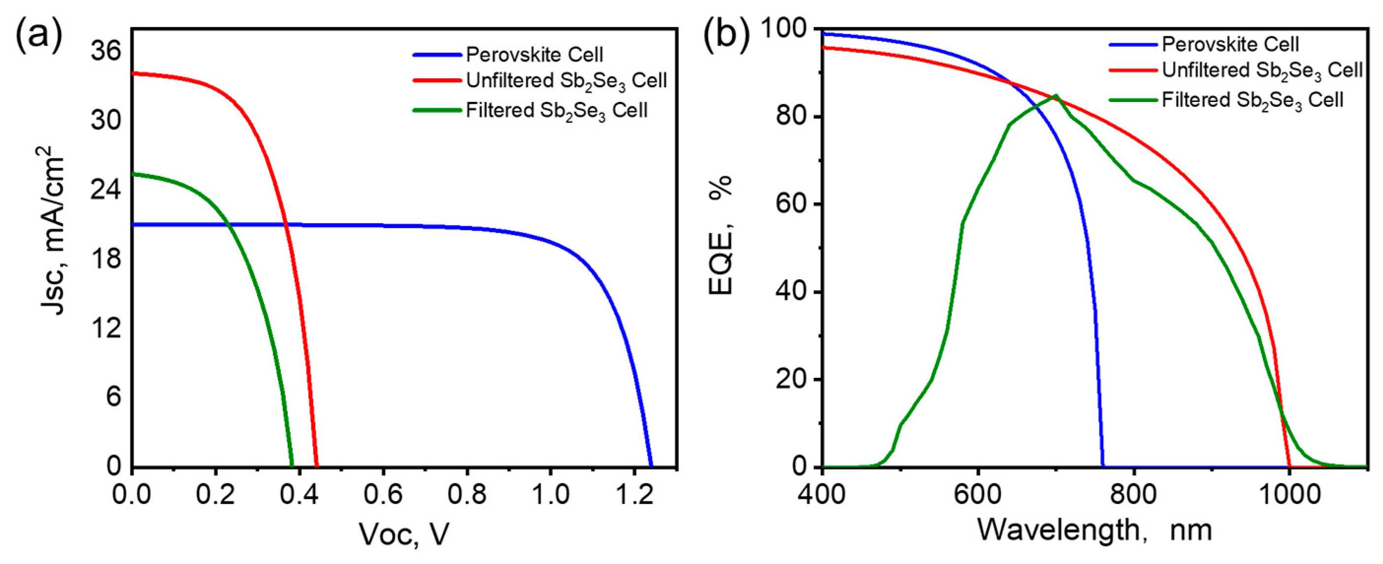
3.1. SCAPS Simulation

For tandem cell application, one of the challenges is to form a transparent electrode for the WBG top cell to transmit the sunlight after absorption by the WBG perovskite. The AM1.5 sun spectra for the top perovskite solar cell before and after filtering is shown in Figure 1a. The transmittance of the two 1.6 eV and 1.77 eV perovskite films and the Sb2Se3 were characterized, as shown in Figure 1b. It is shown that most of the sunlight can be absorbed by perovskite below 650 and 800 nm for the 1.77 eV and the 1.6 eV films, respectively, while the light from 700 to 1100 nm can be absorbed by the 1.2 eV Sb2Se3, demonstrating that the tandem device design is suitable, as shown in Figure 1c.
To simulate the 4T tandem solar cell, we focus on the PSCs with a bandgap of 1.6 eV and extend to the 1.77 eV PSC during the experimental validation. We first simulated the top cell with the standard AM 1.5 G one sun spectrum, which was followed by the filtration of the incident AM 1.5 G spectrum using the model mentioned below.
S λ = S 0 ( λ ) . e x p { i = 1 4 a   mati λ dmati }
where S0(λ) is the incident A.M 1.5G spectrum, S(λ) is the filtered spectrum from the top cell, α(λ) is the absorption coefficient, and “mati” represents a particular material (i = 1 for Spiro-OMeTAD, 2 for perovskite material, 3 for SnO2 and 4 for ITO) for the top perovskite cell and d is the thickness of each layer. The bottom cell was then simulated using the filtered spectrum from the top cell. The detailed material parameters input to SCAPS-1D are shown in Table 1. Input parameters were carefully chosen from the published literature and experimental works and are listed in Table 1 [37,46,47,48].
As shown in Figure 1c, the top cell configurations consist of Spiro-OMeTAD as the HTL, tin oxide (SnO2) as the ETL, and Cs0.04FA0.81MA0.15PbI2.49Br0.51 as the WBG (1.6 eV) absorbers, and ITO as the back electrode for the top cells. The bottom cell consists of CdS as the ETL, Sb2Se3 (1.2 eV) as the NBG absorber layer, and carbon as the back contact. We performed the simulation of the single-junction solar cell containing the perovskite layer and Sb2Se3 using SCAPS-1D software (SCAPS3.3.09 ) under AM 1.5 G illumination and the filtered spectrum, respectively, as shown in Figure 2. All the simulations have been performed at a temperature of 300 K. Further, the losses due to the reflection at interfaces, as well as series resistance of the device, have not been taken into consideration.
Figure 2a shows the current density vs. voltage (J-V) curves for the 1.6 eV WBG PSC and the 1.2 eV NBG Sb2Se3 bottom cell. For the 4T configuration, the optimum photovoltaic parameters of the top cell and the bottom cell with the AM 1.5 G spectrum and the filtered spectrum, respectively, are listed in Table 2. The simulated J-V curves for both the standalone perovskite and Sb2Se3 are close to the experimental results. By applying the filtered solar spectrum, as shown in Figure 1a, the filtered Sb2Se3 cell device performance can be achieved. It is shown that the filtered Sb2Se3 possesses a reduced Jsc and FF. Thus, from the simulation for the 4T device design, the maximum PCE achieved is 23.1%, which is higher than either of the individual cells, which have a PCE of 19.62% and 8.62% (top and bottom cells, respectively). The external quantum efficiency (EQE) of the two cells is also shown in Figure 2b. The onset wavelength of the perovskite top cell is ~770 nm, while the bottom cell onset is around 1000 nm. The EQE spectra of the filtered bottom Sb2Se3 cell indicate that the perovskite can match well with the Sb2Se3 to maximize sunlight absorption. This indicates that the 4T tandem device configuration with the WBG PSC cell and the Sb2Se3 cell exhibits an excellent overall QE that spans the visible and infrared regions of the electromagnetic spectrum.

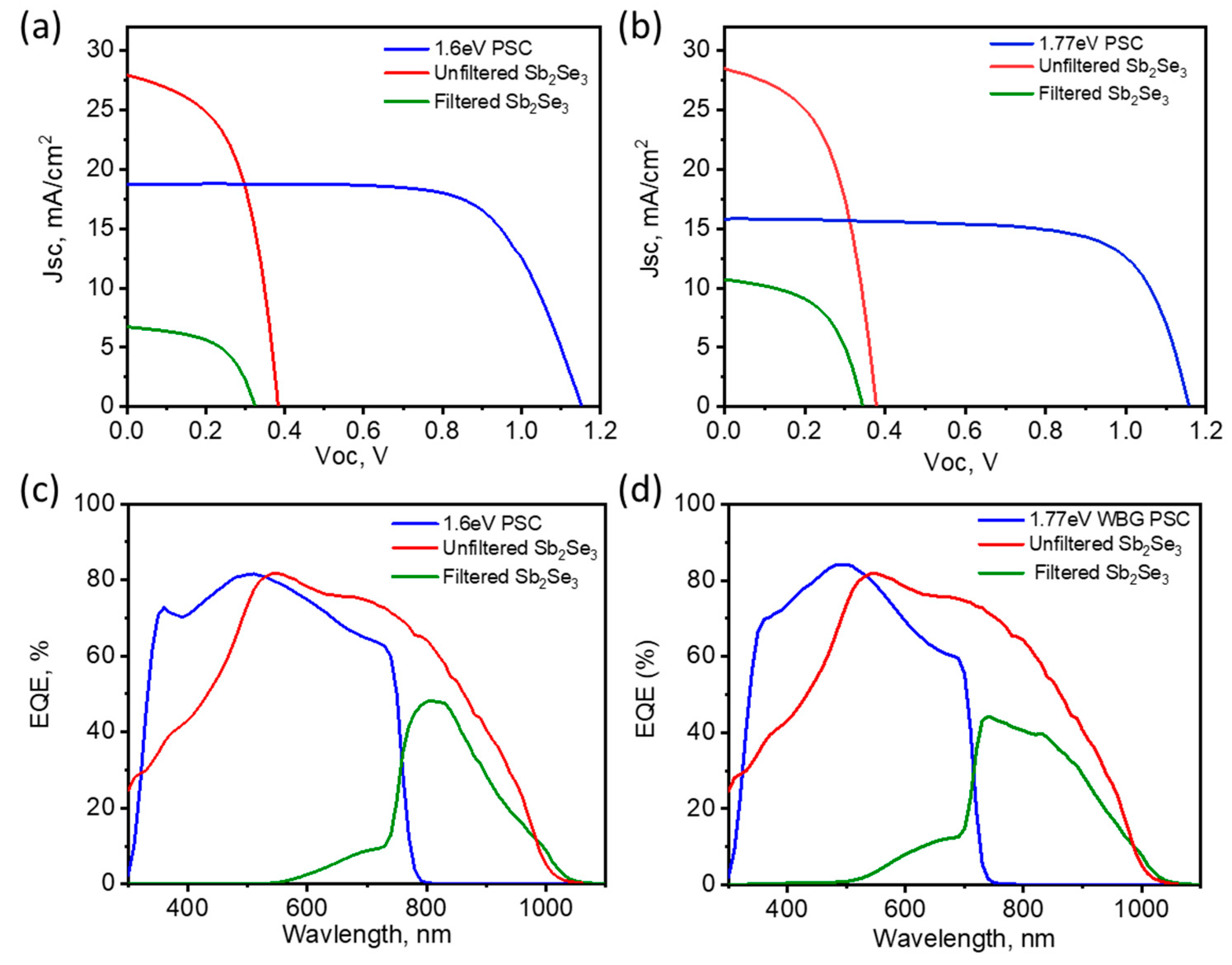
3.2. 4T Perovskite/Sb2Se3 Tandem Cell Performance

To validate the results for the simulated perovskite/Sb2Se3 tandem cells, we fabricated the 4T tandem configuration by mechanically stacking the top perovskite solar cell and the Sb2Se3 bottom cells. To understand the impact of the perovskite bandgap on the 4T tandem solar cell performance, we fabricated two WBG PSCs with a bandgap of 1.6 eV and 1.77 eV with the composition of Cs0.04FA0.81MA0.15PbI2.49Br0.51 and FA0.8Cs0.2Pb(I0.7Br0.3)3, respectively. For the two single-junction PSCs with PCEs of 14.95% and 13%, and the Sb2Se3 with a PCE of ~5.76% used in this work, the detailed device parameters are listed in Table 3. The primary goal here is to prototype the 4T tandem concept using reasonable device performance for each subcell. Our work is in line with the latest reported perovskite and Sb2Se3 four-terminal tandem devices, as listed in Table 3, where the perovskite top cells have a relatively lower bandgap and higher device performance, which promise a higher tandem power conversion efficiency than this work [49]. It is demonstrated that the bandgap match between the top perovskite solar cell and bottom antimony selenide solar cell has big room to be further investigated. In the 4T configuration, the PSC was mechanically stacked on top of the Sb2Se3 solar cell. As shown in Figure 3a, when the top perovskite filter was applied, the Jsc of the Sb2Se3 cell was significantly reduced from 27.86 mA/cm2 to 6.7 and 10.7 mA/cm2, respectively, by employing the 1.6 eV and 1.77 eV perovskite filters. The PSC with a 1.6 eV bandgap and the filtered NBG Sb2Se3 cell had PCEs of 14.95% and 1.18%, respectively, making the overall 4T tandem device have a PCE of 16.13%. The PSC with 1.77 eV had a PCE of 13% and the filtered NBG Sb2Se3 had a PCE of 1.96%, giving an overall 4T tandem PCE of 14.96%. Note that the device performance for the two wide bandgap perovskites is similar to the recently reported perovskite/Sb2Se3, which has a bandgap of 1.58 eV for the top perovskite subcells, as shown in Table 3 [50]. The improved device is majorly from the top perovskite cells. In addition, the bandgap engineering between the top perovskite and bottom Sb2Se3 seems play an important role in the overall tandem device performance, which should be further studied in the future. The top solar cell acts as an optical filter on the Sb2Se3 cell and absorbs wavelengths between 300 and 700 nm, whereas the unabsorbed light, especially that at longer wavelengths, is expected to be harvested by the Sb2Se3 bottom solar cell. The efficiency of the 4T tandem solar cell is higher than that of both perovskite and Sb2Se3 cells, demonstrating that further improvement of the perovskite and Sb2Se3 can further improve the device performance. In addition, further engineering of each layer’s thickness and the device architecture by employing another transparent inter-electrode deposition approach may further improve the top perovskite solar cell performance and the overall tandem device performance.
To further elucidate the wavelength-dependent photon–electron transition, EQE was performed for both 1.6 eV and 1.77 eV-based perovskite 4T tandem cells. The individual EQE spectra for the top perovskite cell and the bottom Sb2Se3 cells and the filtered bottom Sb2Se3 cells are shown in Figure 3c,d. It is shown that the perovskite top cells have an onset wavelength of 790 and 760 nm, respectively, while the bottom Sb2Se3 has an onset wavelength of 1050 nm. Thus, the top and bottom cells are matched well to maximize light absorption. As shown in Figure 3c,d, the sum of the Jsc of the subcells is 25.42 and 26.53 mA/cm2 for the 1.6 and 1.77 eV perovskite top cells. The FF for the filtered bottom cells did not change too much, while the Voc is slightly less compared to the unfiltered bottom cell. Even though the wider bandgap of the 1.77 eV PSC allows for more performance from the filtered Sb2Se3 bottom cell, the effect of the higher PCE of the 1.66 eV PSC outperforms this and results in higher efficiency of the 4T tandem cell.
Therefore, we validate that the PV parameters obtained in the experiments are close to the simulated results. However, there are still mismatches between the model and experiment results. For example, the efficiency for our WBG perovskites is still lower than that of the simulated one, which could be due to the damage from the sputtered ITO electrode. In addition, the bottom Sb2Se3 cell has low efficiency, and further improvements are needed, for example, by converting the four-terminal tandem solar cell into a two-terminal tandem solar cell to minimize the efficiency loss due to the current mismatch between the top and bottom subcells. It is critical to find the suitable interconnection layer to bridge the two subcells, such as a transparent conducting layer on top of the Sb2Se3 cell. In addition, bandgap engineering is still needed to efficiently capture a broad range of the solar spectrum. In a two-terminal configuration, the bandgap of each subcell should be optimized to ensure the efficient absorption of photons while maintaining a good current match. The requirement includes the precise control over the material properties, layer thickness, and device configuration. Meanwhile, the manufacturing cost should be further reduced for the two-terminal tandem solar cells, which is a bottleneck for scaled up production [50,51]. Overall, we provide an effective way to utilize the relatively low-efficiency Sb2Se3 solar technology as a bottom cell for the wide bandgap perovskite. It is demonstrated that the tandem architecture between the perovskite and antimony chalcogenide could be the desired match to maximize sunlight conversion.

4. Conclusions

In summary, we demonstrate a 4T tandem solar cell based on WBG PSC and NBG Sb2Se3 cells. We found that the utilization of WBG PSC and Sb2Se3 as top and bottom cells can generate well-matched spectral utilization. From the simulation, we predict the possibility of forming a 4T tandem cell with a PCE exceeding 23%. We then experimentally fabricated two WBG PSC with bandgaps of 1.6 eV and 1.77 eV, and, on pairing with the Sb2Se3 cell, it demonstrated PCEs of 16.13% and 14.96%, respectively. This efficiency is much higher than the Sb2Se3 standalone cells and provides an alternative way to boost the antimony chalcogenide device performance and utilize its lower bandgap features to maximize sunlight conversion. These perovskite/Sb2Se3 tandem solar cells can be further improved by addressing the individual subcell’s performance. Research indicates that the highest efficiency perovskite solar cells have a significant impact on the performance of tandem devices. With the recent advancement of 26% perovskite solar cell technology, there is potential for perovskite/Sb2Se3 tandem solar technology to offer a cost-effective alternative for scaling up thin film solar technology in the form of a tandem solar module. This paves the way to further develop low-cost and earth-abundant solar cell technology.

Author Contributions

H.M. and A.A. methodology; software, X.D. and S.N.V.; validation, J.W., W.X. and K.A.K.; writing—original draft preparation, H.M.; writing—review and editing, F.Y.; supervision, F.Y.; funding acquisition, F.Y. All authors have read and agreed to the published version of the manuscript.

Funding

This research was funded by National Science Foundation, grant numbers CMMI-2226918, DMR-2330738, CMMI-2330728, TI-2329871, ECCS-1944374, and OISE-2153439. This material is based upon work supported by the U.S. Department of Energy’s Office of Energy Efficiency and Renewable Energy (EERE) under the Solar Energy Technologies Office Award number DE-EE0009833.

Institutional Review Board Statement

Not applicable.

Informed Consent Statement

Not applicable.

Data Availability Statement

The data are available upon request.

Conflicts of Interest

The authors declare no conflicts of interest.

References

  1. Leijtens, T.; Bush, K.A.; Prasanna, R.; McGehee, M.D. Opportunities and challenges for tandem solar cells using metal halide perovskite semiconductors. Nat. Energy 2018, 3, 828–838. [Google Scholar] [CrossRef]
  2. Zhao, D.; Wang, C.; Song, Z.; Yu, Y.; Chen, C.; Zhao, X.; Zhu, K.; Yan, Y. Four-terminal all-perovskite tandem solar cells achieving power conversion efficiencies exceeding 23%. ACS Energy Lett. 2018, 3, 305–306. [Google Scholar] [CrossRef]
  3. Zhao, D.; Yu, Y.; Wang, C.; Liao, W.; Shrestha, N.; Grice, C.R.; Cimaroli, A.J.; Guan, L.; Ellingson, R.J.; Zhu, K. Low-bandgap mixed tin–lead iodide perovskite absorbers with long carrier lifetimes for all-perovskite tandem solar cells. Nat. Energy 2017, 2, 17018. [Google Scholar] [CrossRef]
  4. Eperon, G.E.; Leijtens, T.; Bush, K.A.; Prasanna, R.; Green, T.; Wang, J.T.-W.; McMeekin, D.P.; Volonakis, G.; Milot, R.L.; May, R. Perovskite-perovskite tandem photovoltaics with optimized band gaps. Science 2016, 354, 861–865. [Google Scholar] [CrossRef] [PubMed]
  5. Werner, J.; Weng, C.-H.; Walter, A.; Fesquet, L.; Seif, J.P.; De Wolf, S.; Niesen, B.; Ballif, C. Efficient monolithic perovskite/silicon tandem solar cell with cell area > 1 cm2. J. Phys. Chem. Lett. 2016, 7, 161–166. [Google Scholar] [CrossRef]
  6. Wali, Q.; Elumalai, N.K.; Iqbal, Y.; Uddin, A.; Jose, R. Tandem perovskite solar cells. Renew. Sustain. Energy Rev. 2018, 84, 89–110. [Google Scholar] [CrossRef]
  7. Rohatgi, A.; Zhu, K.; Tong, J.; Kim, D.H.; Reichmanis, E.; Rounsaville, B.; Prakash, V.; Ok, Y.-W. 26.7% Efficient 4-Terminal Perovskite–Silicon Tandem Solar Cell Composed of a High-Performance Semitransparent Perovskite Cell and a Doped Poly-Si/SiO x Passivating Contact Silicon Cell. IEEE J. Photovolt. 2020, 10, 417–422. [Google Scholar] [CrossRef]
  8. Shen, H.; Walter, D.; Wu, Y.; Fong, K.C.; Jacobs, D.A.; Duong, T.; Peng, J.; Weber, K.; White, T.P.; Catchpole, K.R. Monolithic perovskite/Si tandem solar cells: Pathways to over 30% efficiency. Adv. Energy Mater. 2020, 10, 1902840. [Google Scholar] [CrossRef]
  9. Kim, T.S.; Kim, H.J.; Han, J.-H.; Choi, W.J.; Yu, K.J. Flexible InGaP/GaAs Tandem Solar Cells Encapsulated with Ultrathin Thermally Grown Silicon Dioxide as a Permanent Water Barrier and an Antireflection Coating. ACS Appl. Energy Mater. 2022, 5, 227–233. [Google Scholar] [CrossRef]
  10. Chen, Q.; Zhou, L.; Zhang, J.; Chen, D.; Zhu, W.; Xi, H.; Zhang, J.; Zhang, C.; Hao, Y. Recent Progress of Wide Bandgap Perovskites towards Two-Terminal Perovskite/Silicon Tandem Solar Cells. Nanomaterials 2024, 14, 202. [Google Scholar] [CrossRef]
  11. Ašmontas, S.; Mujahid, M. Recent Progress in Perovskite Tandem Solar Cells. Nanomaterials 2023, 13, 1886. [Google Scholar] [CrossRef] [PubMed]
  12. Ho-Baillie, A.W.Y.; Zheng, J.; Mahmud, M.A.; Ma, F.-J.; McKenzie, D.R.; Green, M.A. Recent progress and future prospects of perovskite tandem solar cells. Appl. Phys. Rev. 2021, 8, 041307. [Google Scholar] [CrossRef]
  13. Liu, L.; Xiao, H.; Jin, K.; Xiao, Z.; Du, X.; Yan, K.; Hao, F.; Bao, Q.; Yi, C.; Liu, F.; et al. 4-Terminal Inorganic Perovskite/Organic Tandem Solar Cells Offer 22% Efficiency. Nano-Micro Lett. 2022, 15, 23. [Google Scholar] [CrossRef] [PubMed]
  14. Huang, J.; Yuan, Y.; Shao, Y.; Yan, Y. Understanding the physical properties of hybrid perovskites for photovoltaic applications. Nat. Rev. Mater. 2017, 2, 17042. [Google Scholar] [CrossRef]
  15. Sharma, R.; Sharma, A.; Agarwal, S.; Dhaka, M. Stability and efficiency issues, solutions and advancements in perovskite solar cells: A review. Sol. Energy 2022, 244, 516–535. [Google Scholar] [CrossRef]
  16. Sato, Y.; Takehisa, H.; Kamatsuki, K.; Minami, H.; Namiki, N.; Ikawa, H.; Ohyanagi, H.; Sugimoto, K.; Antonio, B.A.; Nagamura, Y. RiceXPro version 3.0: Expanding the informatics resource for rice transcriptome. Nucleic Acids Res. 2013, 41, D1206–D1213. [Google Scholar] [CrossRef]
  17. Green, M.A.; Ho-Baillie, A.; Snaith, H.J. The emergence of perovskite solar cells. Nat. Photonics 2014, 8, 506–514. [Google Scholar] [CrossRef]
  18. Snaith, H.J. Perovskites: The emergence of a new era for low-cost, high-efficiency solar cells. J. Phys. Chem. Lett. 2013, 4, 3623–3630. [Google Scholar] [CrossRef]
  19. Bi, D.; Yi, C.; Luo, J.; Décoppet, J.-D.; Zhang, F.; Zakeeruddin, S.M.; Li, X.; Hagfeldt, A.; Grätzel, M. Polymer-templated nucleation and crystal growth of perovskite films for solar cells with efficiency greater than 21%. Nat. Energy 2016, 1, 16142. [Google Scholar] [CrossRef]
  20. Siegler, T.D.; Shimpi, T.M.; Sampath, W.S.; Korgel, B.A. Development of wide bandgap perovskites for next-generation low-cost CdTe tandem solar cells. Chem. Eng. Sci. 2019, 199, 388–397. [Google Scholar] [CrossRef]
  21. Liu, M.; Johnston, M.B.; Snaith, H.J. Efficient planar heterojunction perovskite solar cells by vapour deposition. Nature 2013, 501, 395–398. [Google Scholar] [CrossRef] [PubMed]
  22. Bush, K.A.; Palmstrom, A.F.; Yu, Z.J.; Boccard, M.; Cheacharoen, R.; Mailoa, J.P.; McMeekin, D.P.; Hoye, R.L.; Bailie, C.D.; Leijtens, T. 23.6%-efficient monolithic perovskite/silicon tandem solar cells with improved stability. Nat. Energy 2017, 2, 17009. [Google Scholar] [CrossRef]
  23. Werner, J.; Niesen, B.; Ballif, C. Perovskite/silicon tandem solar cells: Marriage of convenience or true love story?—An overview. Adv. Mater. Interfaces 2018, 5, 1700731. [Google Scholar] [CrossRef]
  24. Zheng, J.; Lau, C.F.J.; Mehrvarz, H.; Ma, F.-J.; Jiang, Y.; Deng, X.; Soeriyadi, A.; Kim, J.; Zhang, M.; Hu, L. Large area efficient interface layer free monolithic perovskite/homo-junction-silicon tandem solar cell with over 20% efficiency. Energy Environ. Sci. 2018, 11, 2432–2443. [Google Scholar] [CrossRef]
  25. Bailie, C.D.; Christoforo, M.G.; Mailoa, J.P.; Bowring, A.R.; Unger, E.L.; Nguyen, W.H.; Burschka, J.; Pellet, N.; Lee, J.Z.; Grätzel, M. Semi-transparent perovskite solar cells for tandems with silicon and CIGS. Energy Environ. Sci. 2015, 8, 956–963. [Google Scholar] [CrossRef]
  26. Shen, H.; Peng, J.; Jacobs, D.; Wu, N.; Gong, J.; Wu, Y.; Karuturi, S.K.; Fu, X.; Weber, K.; Xiao, X. Mechanically-stacked perovskite/CIGS tandem solar cells with efficiency of 23.9% and reduced oxygen sensitivity. Energy Environ. Sci. 2018, 11, 394–406. [Google Scholar] [CrossRef]
  27. Paetzold, U.; Jaysankar, M.; Gehlhaar, R.; Ahlswede, E.; Paetel, S.; Qiu, W.; Bastos, J.; Rakocevic, L.; Richards, B.; Aernouts, T. Scalable perovskite/CIGS thin-film solar module with power conversion efficiency of 17.8%. J. Mater. Chem. A 2017, 5, 9897–9906. [Google Scholar] [CrossRef]
  28. Leijtens, T.; Prasanna, R.; Bush, K.A.; Eperon, G.E.; Raiford, J.A.; Gold-Parker, A.; Wolf, E.J.; Swifter, S.A.; Boyd, C.C.; Wang, H.-P. Tin–lead halide perovskites with improved thermal and air stability for efficient all-perovskite tandem solar cells. Sustain. Energy Fuels 2018, 2, 2450–2459. [Google Scholar] [CrossRef]
  29. Rajagopal, A.; Yang, Z.; Jo, S.B.; Braly, I.L.; Liang, P.W.; Hillhouse, H.W.; Jen, A.K.Y. Highly efficient perovskite–perovskite tandem solar cells reaching 80% of the theoretical limit in photovoltage. Adv. Mater. 2017, 29, 1702140. [Google Scholar] [CrossRef]
  30. Forgács, D.; Gil-Escrig, L.; Pérez-Del-Rey, D.; Momblona, C.; Werner, J.; Niesen, B.; Ballif, C.; Sessolo, M.; Bolink, H.J. Efficient monolithic perovskite/perovskite tandem solar cells. Adv. Energy Mater. 2017, 7, 1602121. [Google Scholar] [CrossRef]
  31. Li, Z.; Liang, X.; Li, G.; Liu, H.; Zhang, H.; Guo, J.; Chen, J.; Shen, K.; San, X.; Yu, W. 9.2%-efficient core-shell structured antimony selenide nanorod array solar cells. Nat. Commun. 2019, 10, 1301846. [Google Scholar] [CrossRef]
  32. Zhou, Y.; Leng, M.; Xia, Z.; Zhong, J.; Song, H.; Liu, X.; Yang, B.; Zhang, J.; Chen, J.; Zhou, K. Solution-processed antimony selenide heterojunction solar cells. Adv. Energy Mater. 2014, 4, 1301846. [Google Scholar] [CrossRef]
  33. Wang, X.; Tang, R.; Wu, C.; Zhu, C.; Chen, T. Development of antimony sulfide–selenide Sb2(S, Se)3-based solar cells. J. Energy Chem. 2018, 27, 713–721. [Google Scholar] [CrossRef]
  34. Tang, R.; Chen, S.; Zheng, Z.-H.; Su, Z.-H.; Luo, J.-T.; Fan, P.; Zhang, X.-H.; Tang, J.; Liang, G.-X. Heterojunction Annealing Enabling Record Open-Circuit Voltage in Antimony Triselenide Solar Cells. Adv. Mater. 2022, 34, 2109078. [Google Scholar] [CrossRef]
  35. Liang, G.; Chen, M.; Ishaq, M.; Li, X.; Tang, R.; Zheng, Z.; Su, Z.; Fan, P.; Zhang, X.; Chen, S. Crystal Growth Promotion and Defects Healing Enable Minimum Open-Circuit Voltage Deficit in Antimony Selenide Solar Cells. Adv. Sci. 2022, 9, 2105142. [Google Scholar] [CrossRef]
  36. Lin, J.; Chen, G.; Ahmad, N.; Ishaq, M.; Chen, S.; Su, Z.; Fan, P.; Zhang, X.; Zhang, Y.; Liang, G. Back contact interfacial modification mechanism in highly-efficient antimony selenide thin-film solar cells. J. Energy Chem. 2023, 80, 256–264. [Google Scholar] [CrossRef]
  37. Al Ahmed, S.R.; Sunny, A.; Rahman, S. Performance enhancement of Sb2Se3 solar cell using a back surface field layer: A numerical simulation approach. Sol. Energy Mater. Sol. Cells 2021, 221, 110919. [Google Scholar] [CrossRef]
  38. Amin, A.; Guo, L.; Vijayaraghavan, S.N.; Li, D.; Duan, X.; Menon, H.G.; Wall, J.; Gupta, S.; Cheng, M.; Zheng, Y.; et al. Solution-processed vanadium oxides as a hole-transport layer for Sb2Se3 thin-film solar cells. Sol. Energy 2022, 231, 1–7. [Google Scholar] [CrossRef]
  39. Zhang, J.; Lian, W.; Yin, Y.; Wang, X.; Tang, R.; Qian, C.; Hao, X.; Zhu, C.; Chen, T. All antimony chalcogenide tandem solar cell. Sol. RRL 2020, 4, 2000048. [Google Scholar] [CrossRef]
  40. Amin, A.; Li, D.; Duan, X.; Vijayaraghavan, S.; Menon, H.G.; Wall, J.; Weaver, M.; Cheng, M.M.C.; Zheng, Y.; Li, L. Enhanced Efficiency and Stability in Sb2S3 Seed Layer Buffered Sb2Se3 Solar Cells. Adv. Mater. Interfaces 2022, 9, 2200547. [Google Scholar] [CrossRef]
  41. Akshay, V.V.; Benny, S.; Bhat, S.V. Solution-processed antimony chalcogenides based thin film solar cells: A brief overview of recent developments. Sol. Energy 2022, 241, 728–737. [Google Scholar] [CrossRef]
  42. Burgelman, M.; Nollet, P.; Degrave, S. Modelling polycrystalline semiconductor solar cells. Thin Solid Film. 2000, 361–362, 527–532. [Google Scholar] [CrossRef]
  43. Vijayaraghavan, S.; Wall, J.; Li, L.; Xing, G.; Zhang, Q.; Yan, F. Low-temperature processed highly efficient hole transport layer free carbon-based planar perovskite solar cells with SnO2 quantum dot electron transport layer. Mater. Today Phys. 2020, 13, 100204. [Google Scholar] [CrossRef]
  44. Nakamura, M.; Lin, C.C.; Nishiyama, C.; Tada, K.; Bessho, T.; Segawa, H. Semi-transparent Perovskite Solar Cells for Four-Terminal Perovskite/CIGS Tandem Solar Cells. ACS Appl. Energy Mater. 2022, 5, 8103–8111. [Google Scholar] [CrossRef]
  45. Vijayaraghavan, S.; Wall, J.; Menon, H.G.; Duan, X.; Guo, L.; Amin, A.; Han, X.; Kong, L.; Zheng, Y.; Li, L. Interfacial engineering with NiOx nanofibers as hole transport layer for carbon-based perovskite solar cells. Sol. Energy 2021, 230, 591–597. [Google Scholar] [CrossRef]
  46. Islam, M.; Jani, M.; Rahman, S.; Shorowordi, K.M.; Nishat, S.S.; Hodges, D.; Banerjee, S.; Efstathiadis, H.; Carbonara, J.; Ahmed, S. Investigation of non-Pb all-perovskite 4-T mechanically stacked and 2-T monolithic tandem solar devices utilizing SCAPS simulation. SN Appl. Sci. 2021, 3, 504. [Google Scholar] [CrossRef]
  47. Islam, M.T.; Jani, M.R.; Al Amin, S.M.; Sami, M.S.U.; Shorowordi, K.M.; Hossain, M.I.; Devgun, M.; Chowdhury, S.; Banerje, S.; Ahmed, S. Numerical simulation studies of a fully inorganic Cs2AgBiBr6 perovskite solar device. Opt. Mater. 2020, 105, 109957. [Google Scholar] [CrossRef]
  48. Karthick, S.; Velumani, S.; Bouclé, J. Experimental and SCAPS simulated formamidinium perovskite solar cells: A comparison of device performance. Sol. Energy 2020, 205, 349–357. [Google Scholar] [CrossRef]
  49. Cai, Z.; Sun, J.; Cai, H.; Gu, Y.; Tang, R.; Zhu, C.; Luo, P.; Chen, T. Sb2Se3 as a bottom cell material for efficient perovskite/Sb2Se3 tandem solar cells. Energy Mater. Devices 2024. online first. [Google Scholar] [CrossRef]
  50. Ruiz-Preciado, M.A.; Gota, F.; Fassl, P.; Hossain, I.M.; Singh, R.; Laufer, F.; Schackmar, F.; Feeney, T.; Farag, A.; Allegro, I.; et al. Monolithic Two-Terminal Perovskite/CIS Tandem Solar Cells with Efficiency Approaching 25%. ACS Energy Lett. 2022, 7, 2273–2281. [Google Scholar] [CrossRef]
  51. Abdollahi Nejand, B.; Ritzer, D.B.; Hu, H.; Schackmar, F.; Moghadamzadeh, S.; Feeney, T.; Singh, R.; Laufer, F.; Schmager, R.; Azmi, R.; et al. Scalable two-terminal all-perovskite tandem solar modules with a 19.1% efficiency. Nat. Energy 2022, 7, 620–630. [Google Scholar] [CrossRef]
Figure 1. (a) The intensity of the unfiltered and filtered AM 1.5 G spectra transmitted through the WBG perovskite layer of the top subcell; (b) transmittance of the wide bandgap perovskite and NBG Sb2Se3 films. One 1.6 eV perovskite film is shown in the inset, and (c) a schematic of the 4T tandem cell.
Solar 04 00010 g001
Figure 2. SCAPS simulated current density–voltage (a) (J-V) curve and (b) EQE of the 1.6 eV WBG PSC top cell, unfiltered Sb2Se3 solar cells, and the filtered Sb2Se3 solar cell.
Solar 04 00010 g002
Figure 3. J-V curves of 4T tandem solar cells with (a) the 1.6 eV PSC top cell and (b) 1.77 eV PSC top cell. EQE curves of 4T tandem solar cells with (c) the 1.6 eV PSC top cell and (d) 1.77 eV PSC top cell.
Solar 04 00010 g003
Table 1. Parameters of materials used in the simulation of the 4T tandem solar cells.
ParameterHTLPSCSnO2ITOFTOCdSSb2Se3
Thickness (nm)25050010010030050400
Bandgap (eV)3.061.63.53.723.52.41.2
Electron Affinity (eV)2.23.94.03.64.54.33.9
Dielectric Permittivity3.0109.01010.09.3515
Conduction Band of State (cm−3)2.8 × 10192.2 × 10182.2 × 10174 × 10192.2 × 10182.2 × 10182.2 × 1018
Valence Band of States (cm−3)2.2 × 10191.8 × 10182.2 × 10171 × 10182.2 × 10181.8 × 10191.8 × 1019
Electron Mobility (cm2/Vs)1 × 10−41.66203010010015
Hole Mobility (cm2/Vs)2 × 10−41.60105.020255
Donor Concentration (cm−3)0.01.0 × 1091.0 × 10181 × 1091.0 × 10177 × 10160
Acceptor Concentration (cm−3)1.0 × 10181.0 × 1090 003.0 × 10¹³
Ref.[37][38][39][39][29][29][29]
Table 2. Photovoltaic parameters of the 1.6 eV WBG PSC, Sb2Se3 cells, and the resulting 4T tandem solar cell efficiency.
Voc (V)Jsc (mA/cm2)FF (%)PCE (%)
1.60 eV PSC1.2321.057519.62
Unfiltered Sb2Se30.4434.1357.298.62
PSC Filtered Sb2Se30.3825.4250.913.52
4T Tandem Cell 23.14
Table 3. Photovoltaic parameters of champion semitransparent WBG PSC (1.6 eV and 1.77 eV) cells with Sb2Se3 cells, and the resulting 4T tandem efficiencies.
Voc (V)Jsc (mA/cm2)FF (%)PCE (%)Ref.
1.6 eV WBG PSC1.1518.7267.3414.95
Unfiltered Sb2Se30.3827.8654.045.76
Filtered Sb2Se30.326.7054.521.18
Tandem PCE 16.13This work
1.77 eV WBG PSC1.1615.8368.813
Unfiltered Sb2Se30.3827.8654.045.76
Filtered Sb2Se30.3410.7053.181.96
Tandem PCE 14.96This work
1.58 eV PSC1.0422.6875.54%17.88%
Unfiltered Sb2Se30.4030.0164.96%7.85%
Filtered Sb2Se30.3711.1265.772.70%
Tandem PCE 20.58%Ref. [49]
Disclaimer/Publisher’s Note: The statements, opinions and data contained in all publications are solely those of the individual author(s) and contributor(s) and not of MDPI and/or the editor(s). MDPI and/or the editor(s) disclaim responsibility for any injury to people or property resulting from any ideas, methods, instructions or products referred to in the content.

