
Mechanism of Electropulsing Treatment Technology for Flow Stress of Metal Material: A Review

School of Mechanical Engineering, Sichuan University, Chengdu 610065, China
*
Author to whom correspondence should be addressed.
Alloys 2024, 3(1), 96-125; https://0-doi-org.brum.beds.ac.uk/10.3390/alloys3010006
Submission received: 18 January 2024
/
Revised: 21 February 2024
/
Accepted: 15 March 2024
/
Published: 21 March 2024
Abstract
:Residual stress is caused by non–uniform deformation caused by non–uniform force, heat and composition, which is of great significance in engineering applications. It is assumed that the residual stress is always the upper limit of the elastic limit, so the reduction of the flow stress will reduce the residual elastic stress. It is particularly important to control the flow stress in metal materials. Compared with traditional methods, the use of electropulsing treatment (EPT) technology stands out due to its energy–efficient, highly effective, straightforward and pollution–free characteristics. However, there are different opinions about the mechanism of reducing flow stress through EPT due to the conflation of the effects from pulsed currents. Herein, a clear correlation is identified between induced stress levels and the application of pulsed electrical current. It was found that the decrease in flow stress is positively correlated with the current density and the duration of electrical contact and current action time. We first systematically and comprehensively summarize the influence mechanisms of EPT on dislocations, phase, textures and recrystallization. An analysis of Joule heating, electron wind effect, and thermal–induced stress within metal frameworks under the influence of pulsed currents was conducted. And the distribution of electric, thermal and stress fields under EPT are discussed in detail based on a finite element simulation (FES). Finally, some new insights into the issues and challenges of flow stress drops caused by EPT are proposed, which is critically important for advancing related mechanism research and the revision of theories and models.
1. Introduction
Residual stress represents the elastic tension maintained within a material, resulting from uneven stress and temperature distributions, as well as irregular structural deformation during manufacturing and processing stages. This phenomenon is a primary factor in the occurrence of brittleness and corrosive cracking in metals [1,2,3]. Based on the range of stresses, there are four types of flow stresses: (i) the first is the stress that exists throughout the material, (ii) the second is the stress within the composition, which is created by the tension and compression of the composition, (iii) the third kind of stress is the non–uniform stress existing in each grain, which is equivalent to the action stress between the actual grains and different phases in the structure, and (iv) the fourth is the more microscopic stress caused by dislocations and various intracrystalline defects [4,5,6,7,8,9]. Seeger et al. [10] considered that the first kind of stress is a constant in the macroscopic range, and the second kind of stress is also a constant in the microscopic domain, which tends to change periodically in the macroscopic range as well as the third kind of stress in the microscopic domain. Given the preparation and treatment of metallic materials, such as drawing [11], extrusion [12], rolling [13], corroding [14], cutting [15], grinding [16], surface rolling [17], shot peening [18], hammering [19], casting [20], quenching heat treatment [21], welding [22], etc., these four types of residual stresses are inevitable.
In the processing of metal materials, the generation of residual stress is unavoidable, and concurrently, such stress can impair the operational efficiency of the material [23,24]. Therefore, it is of utmost significance to manage the residual stress within metal materials [25]. The origins of residual stress encompass three primary factors. (i) Residual stress arises from disparate plastic deformation resulting from applied forces. (ii) Thermal effects produce residual stress; non–uniform temperature changes cause non–uniform thermal expansion. (iii) Residual stress is caused by chemical action; this residual stress is the stress generated by the chemical change or physical change transmitted from the surface to the interior [26,27,28,29,30,31]. In summary, residual stress is caused by non–uniform deformation caused by non–uniform force, heat and composition. It is assumed that the residual stress is always the upper limit of the elastic limit, so a reduction in the flow stress will reduce the residual elastic stress. Therefore, it is particularly important to control the flow stress in metal materials.
The reduction process of flow stress is essentially various inelastic deformations that occur inside the material, and the initiation and development of the deformation process requires energy consumption. Various existing methods of eliminating flow stress have the characteristics of delivering energy to the material to induce the release of flow stress. At present, the main methods for reducing the flow stress are natural aging [32], thermal aging [33], vibration [34], the mechanical stretching method [35], the hammering method [36], etc. Compared with traditional methods, the use of electropulsing treatment (EPT) technology stands out due to its energy–efficient, highly effective, straightforward and pollution–free characteristics.
In recent years, EPT has been a new metal material processing technology [37], which mainly uses high–density energy input and a high–intensity electric field effect to promote the microstructure evolution inside metal materials, thereby improving the performances of the materials [38]. The use of pulsed current to process metal materials has achieved many excellent results that are different from those of traditional processing methods, and it has been widely researched and applied as a potential innovative technology that can break through the bottleneck of traditional processing technology. The current mechanism of flow stress drop under EPT has been accepted due to the fact that the pulse current facilitates the movement of the dislocation, reduces the concentration of stress and reduces the flow stress. In fact, the pulse current can reduce flow stress resulting from the movement of dislocations, the distribution of phases and plastic deformation.
Here, we systematically summarized the mechanisms of flow stress drop under EPT and explored the influences of thermal and non–thermal effects on dislocations, phases, textures and recrystallization. We attempted to construct the mapping relationship between pulse current and stress and used numerical analysis and FES to verify the consistent relationship. Finally, we believe that analyzing the situation of multi–field coupling from a multi–scale perspective is beneficial for promoting mechanism studies on flow stress drop under EPT. This work has important implications for improving mechanical properties under EPT.
2. The Mapping Relationship between Pulse Current and Stress
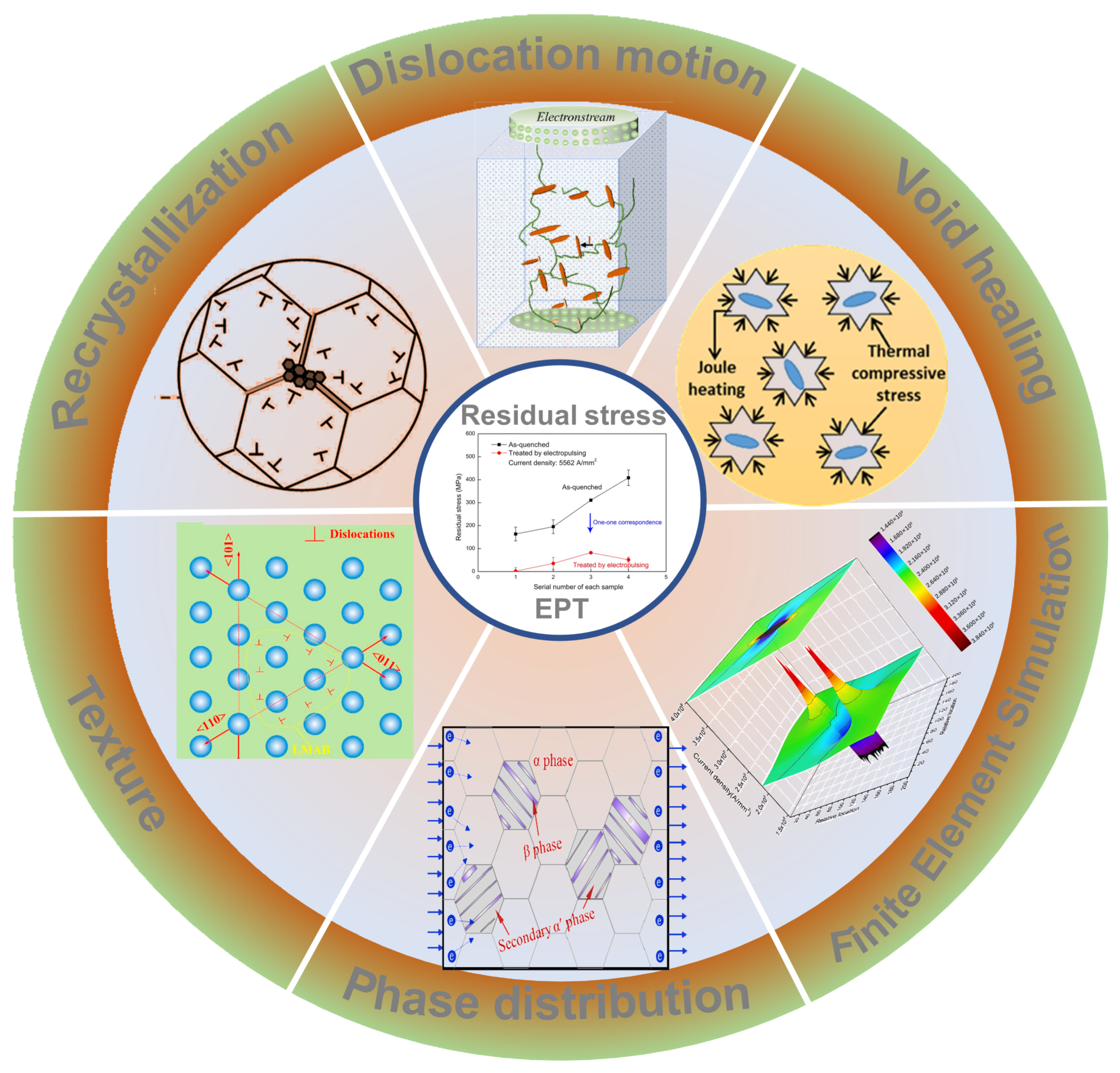
Numerous studies have established that EPT is capable of diminishing the flow stress of metal materials [39]. The research group of Conrad diligently examined the decline in flow stress experienced by metals such as Al, Cu, Ti, Ni, Fe, W and Nb when exposed to electrical pulse stresses during linear tensile strain at a consistent rate [40,41,42,43,44,45]. Their findings indicate a significant reduction in flow stress when metals are subjected to an electrical current pulse with an amperage of 103–104 A/mm2 for 60 μs. Evidently, this induces a relaxation in stress as the current traverses through the metallic framework [46,47,48,49,50]. Up to now, the inherent ability of EPT to reduce flow stress has been reported from different aspects. The flow stress drop mechanism of EPT in terms of the organizational structure and the field variation in FES is illustrated in Figure 1.
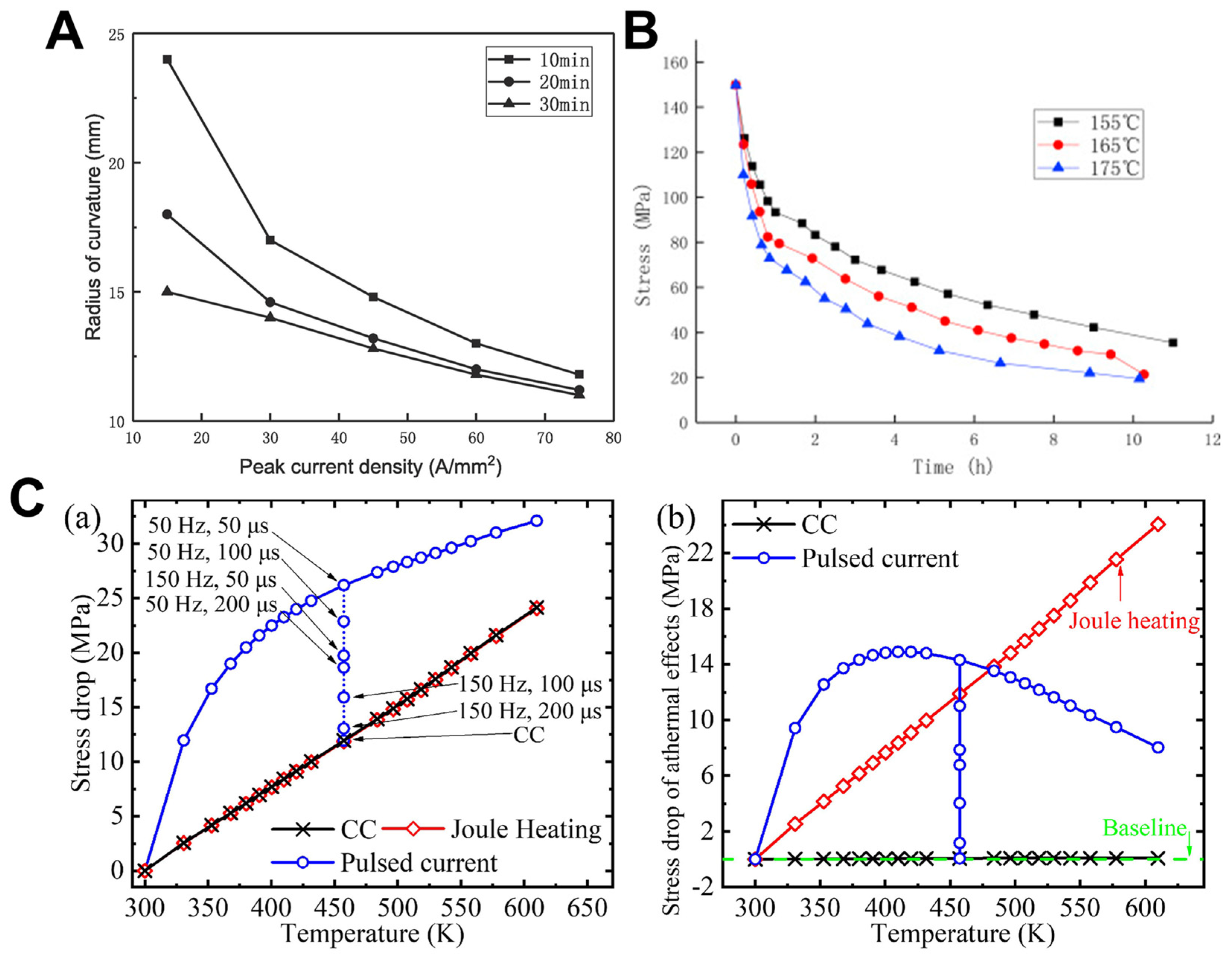
Figure 2A illustrates Li et al.’s [51] methodology, where a pulsed current is injected into the prolonged stress relaxation of nanocrystalline nickel foils, enhancing the relaxation rate. The findings demonstrate that this rate escalates with the introduction of pulsed currents. Additionally, as the magnitude of the pulse current density escalates, so too does the enhancement of the relaxation effect. Zhan et al. [52] devised a constitutive model inspired by aged relaxation in light of pulse current effects during the creep aging deformation process. It has been observed that as temperature elevates, the rate of stress relaxation correspondingly increases, implying that the thermal activation of dislocations is a factor during stress relaxation (refer to Figure 2B). Yang et al. [53]. integrated various effects (magneto–plasticity, Joule heating, electron wind, etc.) to construct a crystal plasticity model, decoupling the non–thermal effects and thermal effects on dislocation activity and quantifying their influence on flow stress. As shown in Figure 2C(a), the difference in stress between the control sample and the sample subjected to applied current at a strain of 0.26% was observed. The stress drop induced by pulsed current is significantly higher than that induced by Joule heating or continuous current, despite the overall temperature being the same. The additional stress drop is attributed to the non–thermal effects induced by pulsed current. Figure 2C(b) demonstrates that, at lower root mean square current densities, the reduction in stress due to Joule heating is smaller than the non–thermal effects of pulsed current. As the root mean square current density increases, the temperature further rises, and the non–thermal effects initially increase and then decrease. This implies the existence of an optimal root mean square current, leading to the most significant stress drop under density and steady–state temperature with prominent magneto–plastic effects.
Concisely, an upsurge in pulse current duration, alongside temperature and current density within prescribed limits, correlates with a reduction in residual stress because of flow stress drop [54]. Nonetheless, the precise dynamics and microstructural mechanisms underpinning the pulse current’s impact on flow stress drop remain obscure, casting doubt on its industrial viability. Next, we try to summarize the research results of pulse current affecting flow stress in metal materials and discuss the influence law and mechanism of pulse current on flow stress in metal materials from the perspectives of dislocations, phases and grains.
3. Effects of EPT on Dislocations
The composition of flow stress, identified as is attributed to both thermal and non–thermal influences induced by the pulse current [55,56]. The correlation between flow stress and the density of dislocations adheres to the Kock-Mecking framework [56,57]:
where represents the baseline stress constant, represents the effective orientation factor of Taylor, is a defined constant, b denotes the Burgers vector, and signifies the modulus of shear elasticity. The magnitude of flow stress is linked to the dislocation’s magnitude squared, and a decline in dislocation density within the crystal matrix contributes to flow stress drop. The formulation for current–assisted dislocation ascension is delineated as follows [58]:
where is the dislocation climbing rate, denotes the atomic transition interval, is the density of vacancy sites in an ideal crystal structure, is the coefficient of vacancy volume diffusion, is a constant, denotes temperature, f/l is the climbing force, and Va is the atomic volume. Joule heat can increase and , and electronic wind can increase and , both of which can promote dislocation climbing and reduce dislocation density.
XRD peak widening as a result of strain serves as a method used to gauge dislocation density [59]. For homogeneous materials, the Williamson–Hall [60] formula is used to infer dislocation density based on X-ray peak expansion:
where is the peak width, stands for a constant, stands for the shape factor, is for the crystallite dimension, and is for the diffraction vector’s intensity. Considering the effect of strain anisotropy, an improved Williamson-Hall formula [61,62] was developed as follows:
In this model, the dislocation contrast factor relates to the Miller indices, remains a non–dimensional constant, and b denotes the Burgers vector. In conclusion, one can ascertain dislocation density empirically from the XRD data of the sample (Figure 3A) [63]. Generally speaking, the dislocation density of metal tends to decrease after EPT, and its dislocation evolution is shown in Figure 3B [64].
3.1. Joule Heat Effect
The process of pulse current input will produce flow around effects in various high–stress areas such as grain boundaries, dislocations, second–phase particles, vacancies, cracks, etc., providing Joule heat to the defect area due to higher resistivity [65]. Joule heat accelerates the movements of dislocations and their climbing and annihilation on grain boundaries, which is beneficial to the homogenization of the organization, thereby resulting in a decrease in flow stress [66].
Contemporary findings indicate that the Joule heating phenomenon can lower the barrier to dislocation motion and enhance the process of dislocation cancellation, consequently decreasing dislocation concentration [67,68,69,70]. Typically, the grid resistance, known as the Peierls–Nabarro force due to the periodically distributed Peierls energy of activation, is the barrier that must be overcome for the dislocation to slip [71,72,73]. Influenced by the kink–pair mechanism, the rate of a moving dislocation over distance is given by
where symbolizes the stress-dependent activation energy, b denotes the Burgers vector, defines the oscillation frequency of the dislocation over wavelength , k denotes the Boltzmann constant, and T stands for temperature. The equation suggests that within the domains of stress and temperature, the kink-pair mechanism benefits from thermal activation, indicating an advantage of increased temperatures for dislocation movement [74].
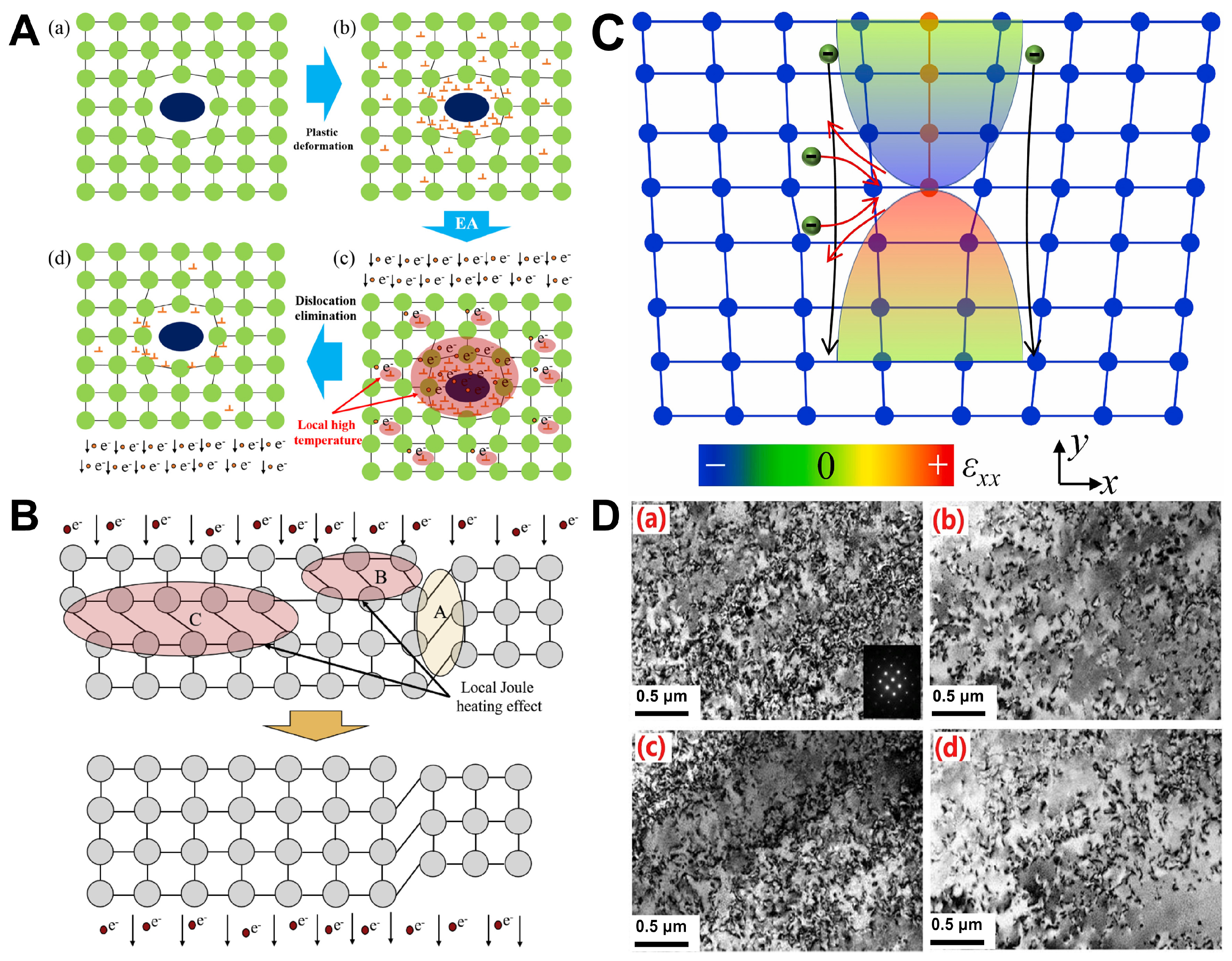
Zhang and his team [75] uncovered a stress–softening occurrence through their investigation on the influence of electric–assisted deformation on nickel–based superalloys’ a-phase, as depicted in Figure 4A. Their conclusion was that the localized Joule heat effect was responsible for this, as it encouraged both dislocation slip and dislocation recovery. Moreover, the quick rate of dislocation recovery resulted in the swift alleviation of dislocations surrounding the δ phase, which they identified as the primary cause for the formation of dislocation–free loops around said δ phase (Figure 4A(c,d)). In a separate study, Zhang and colleagues [76] theorized that dislocations running perpendicular to the current direction could hinder electron movement due to the dislocation region’s high scattering coefficient. The localized Joule heat effect caused temperatures in these areas to rise, and the resulting local high temperature prompted dislocation annihilation (Figure 4B). In Figure 4C, the highest strains can be seen at the top and bottom of the dislocation core, with less strain on the left and right sides. If the electron motion is not aligned with the dislocation, electrons move to either side of the dislocation core and are heavily scattered by the core, as the red curve illustrates. The electron detour results in a high concentration of electrons on either side of the dislocation, causing a significant electron imbalance. However, when electron motion aligns with the dislocation, scattering caused by the strain field is minimal, as demonstrated by the black curve [77]. Zhang et al. [78] suggested that the softening impact of Joule heating lessens the dislocation density (Figure 4D). Briefly, Joule heating promotes the motion of dislocations, causing them to annihilate, thereby reducing dislocation density and flow stress.
3.2. Electronic Wind Effect
During EPT, migratory electrons can produce an electronic wind that influences the dislocations, resulting in an acceleration of dislocation movement due to the electronic wind’s momentum [79]. As the dislocations in the alloy are generally secured by the secondary–phase particles, the unbound ends of the dislocations twist around the secondary–phase particles due to the electric wind force until the dislocation lines align with the flow of current; concurrently, the electronic wind force reaches its minimum impact [80,81]. This phenomenon is a primary factor in the alignment and flattening of dislocations within the alloy’s grains when subjected to pulse current, reflecting the most evident non–thermal consequence of the pulse current.
In 1963, Troitskii and Lichtman first revealed the electron wind effect in metal crystals, that is, the interaction between moving electrons and dislocations [82]. For electronic wind, three models are mainly assumed at present:
Kravchenko’s [83]:
Roschupkin et al.’s [86]:
where stands for the force of drift electrons acting on dislocations per unit length, stands for the electron directional drift rate, stands for the dislocation rate, denotes the Burgers vector mode, e stands for the electron charge, stands for the electron density, stands for the effective electron mass, stands for the Fermi energy, stands for the Fermi rate, stands for Planck’s constant, J stands for current density, and stands for the energy gap. According to the above model, it is clear that the electronic wind force is proportional to the current density, that is to say, the greater the current density, the more obvious the electronic wind effect. Therefore, the expression for the electronic wind force can be mainly assumed as follows [87]:
In this formula, Ked is called the electronic wind coefficient. However, according to Formulas (6)–(8), the calculated Ked values are 10−17, 10−16 and 10−15 Nm/A, respectively. According to the experimental results, Ked is in the order of 10−12 Nm/A.
Furthermore, the current progress of the electronic wind model still relies on a series of publications by Conrad and his colleagues, providing a systematic framework for simulating the electronic wind effect with different models under various assumptions. For instance, in assuming electrostatic equilibrium, under an externally applied current, electrons move continuously without reaching equilibrium. The stress reduction caused by the electronic wind force can be represented by the following equation [88]:
In this formula, represents the decreasing stress, denotes the average dislocation velocity, B stands for the resistance coefficient, and b denotes the Burgers vector. Furthermore, models describing the decrease in flow stress often involve the combined expression of multiple effect mechanisms [53,89], with the individual electron wind effect still exhibiting the aforementioned issues.
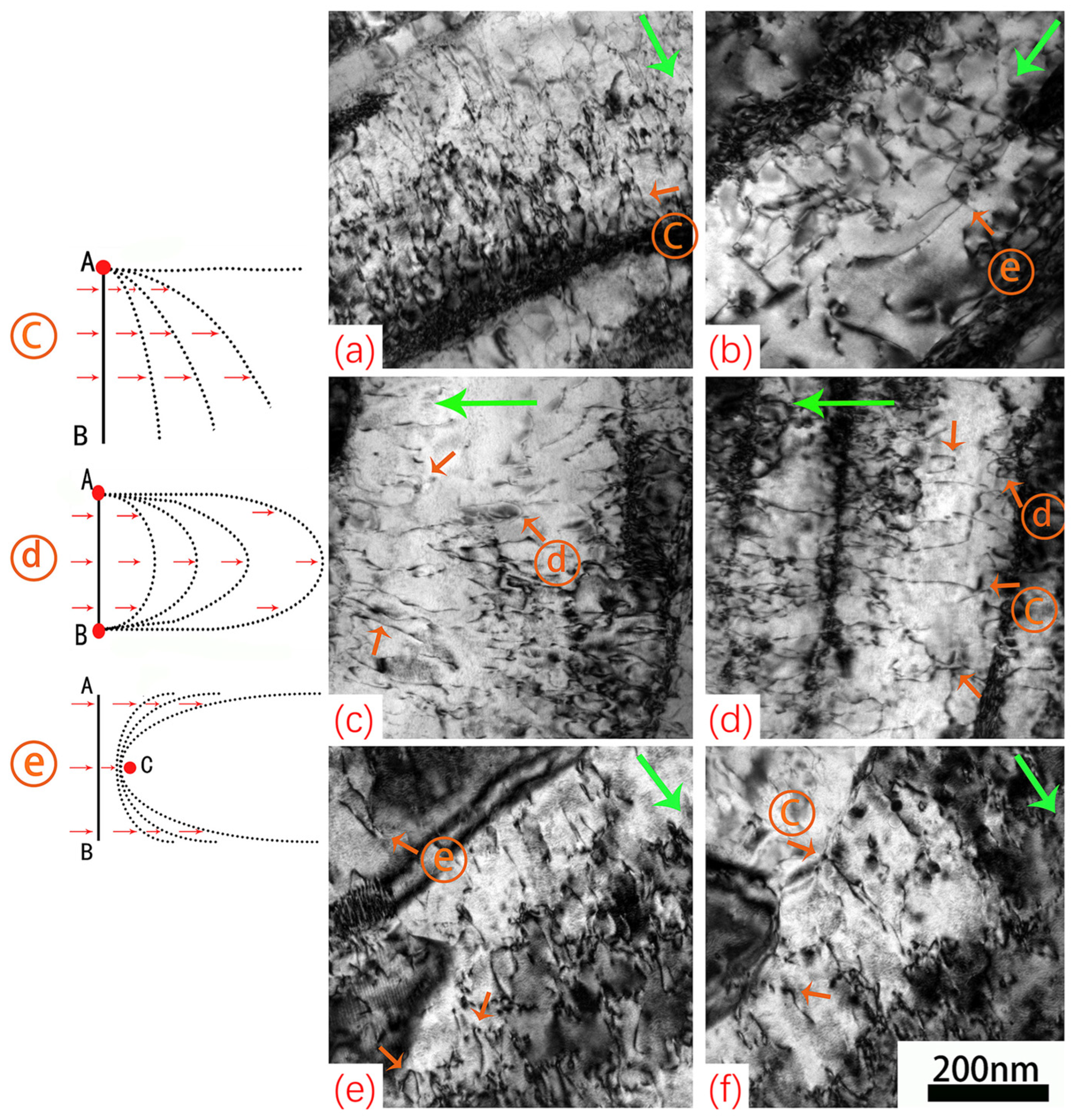
Extensive research indicates that migratory electrons assume a distinctive function in electrical pulse treatment as an ancillary force that advances dislocations [90]. These dislocations ultimately accumulate at the grain boundaries and establish linear configurations [91,92]. As illustrated in Figure 5, the activities of vacancies and dislocations receive an upsurge through the influence of migratory electrons, which promotes the rapid resolution of dislocations. Additionally, with the effect of electronic wind, the Frank–Read [93] source is unable to generate a significant number of dislocations, effectively diminishing the frequency of dislocation propagation. In the end, there are reductions in dislocation concentration and the realignment of dislocation structures in accordance with the trajectory of the migrating electrons. It is noteworthy that this decrease in dislocation density significantly reduces the extent of the flow stress drop [94].
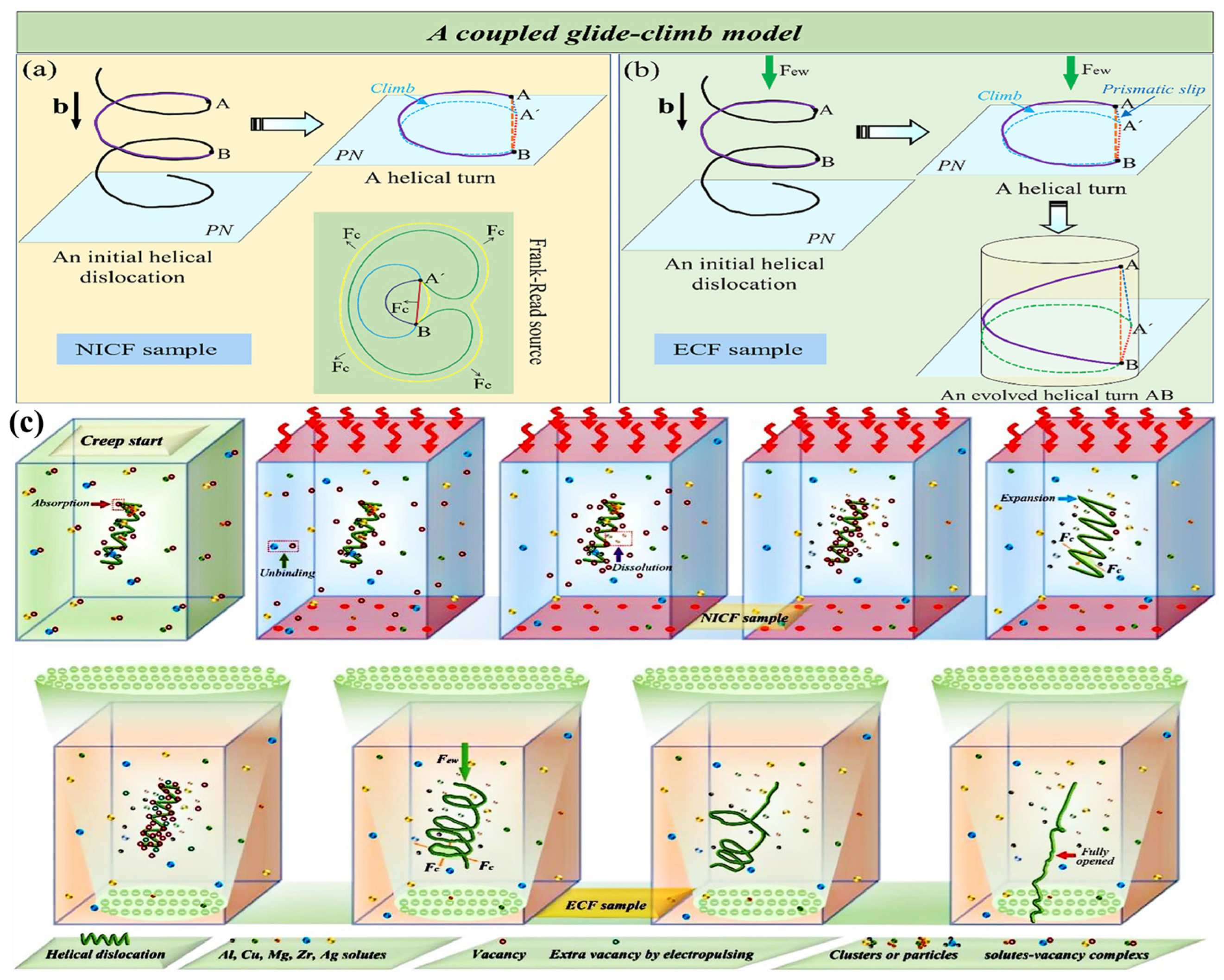
As shown in Figure 6, Zhou et al. [95] designed the non–isothermal creep–age forming (NICF) samples as controls at the same temperature to identify the non–thermal effect of pulsed current. The main climbing force of Fc is the vacancy concentration gradient, which will generate the thermodynamic driving force Fosm. The Fc can drive the edge component to climb along the direction from the normal line to Burgers vectors b, resulting in the gradual expansion of the spiral turn in Figure 6a. The synergistic effect of the electronic wind force Few and the climbing force Fc cause the spiral dislocation to evolve into a conical spiral dislocation and finally into a straight line in assisted creep–age forming (ECF) samples (Figure 6b). A schematic of the dislocation configuration during NICF and ECF sample evolution is shown in Figure 6c.
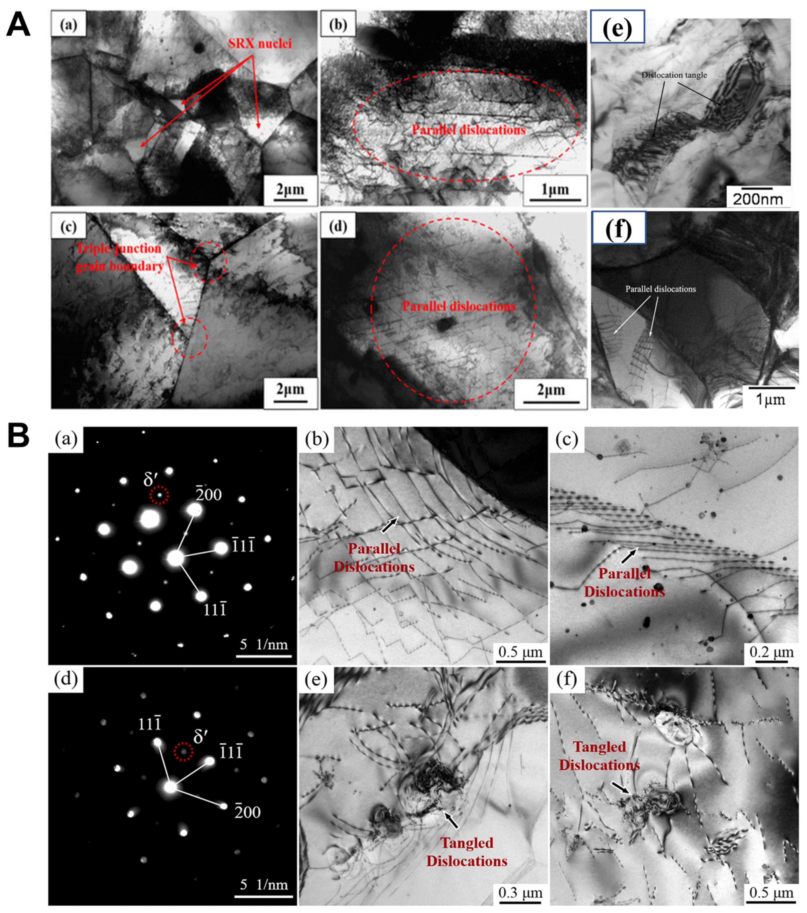
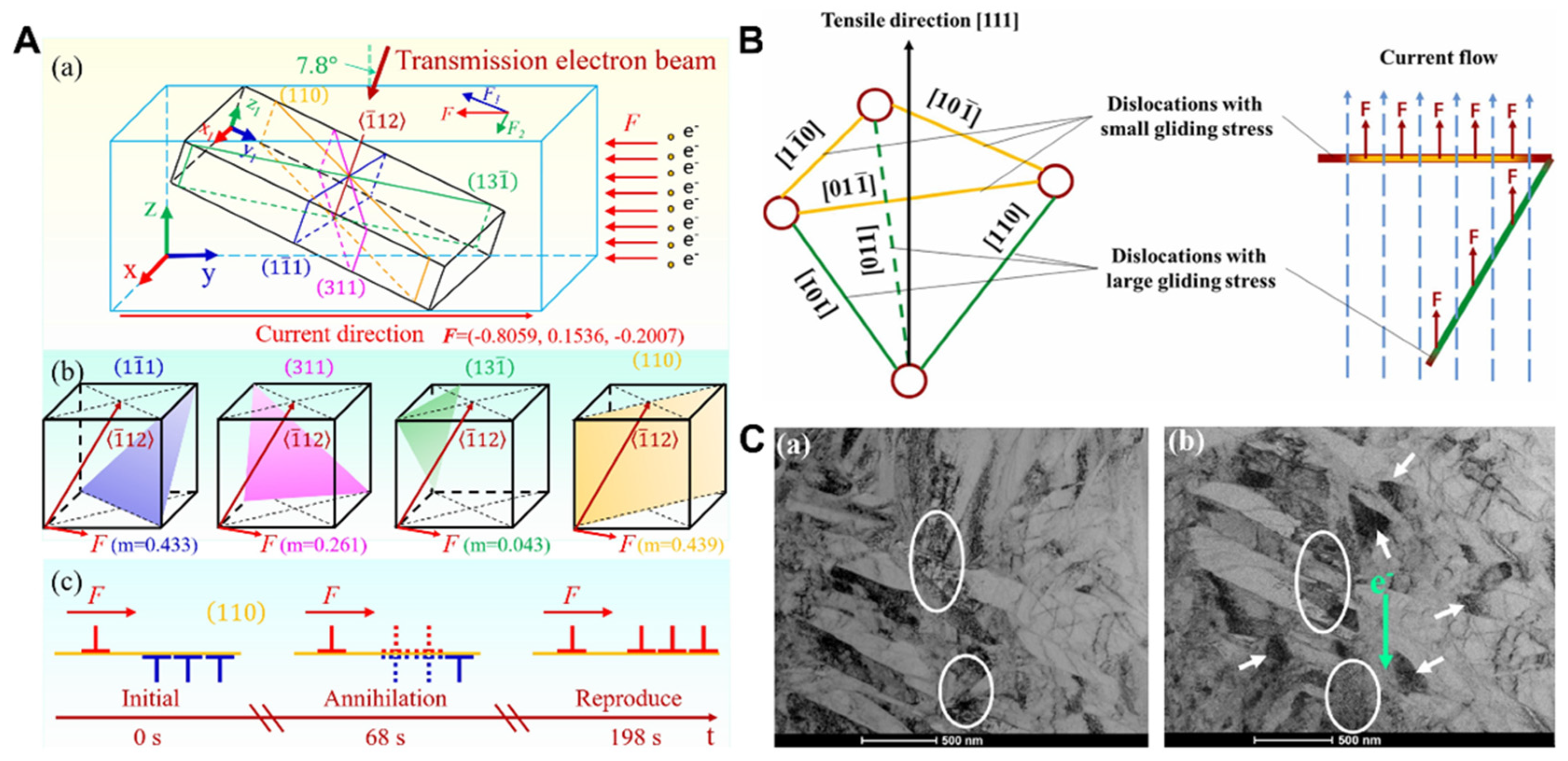
Zhang and colleagues [96] explored how electric pulse treatment (EPT) influences the static recrystallization (SRX) texture in nickel–based superalloys subjected to cold deformation. Their research revealed that the electron wind’s role in generating parallel dislocation arrays can indirectly facilitate the SRX mechanism, as shown in Figure 7A(a–d). Conversely, Zhao and their team [97] proposed that the alignment of dislocations in parallel formations, driven by the electron wind under high–energy pulse currents, plays a pivotal role in dislocation mobility, which is significantly influenced by the electron beam’s total flux, as depicted in Figure 7A(e,f). In a different study, Han and colleagues [69] delved into the impacts of electric currents on the mechanical properties and microstructure transformation of Al–Mg–Li alloys through electric pulse–assisted uniaxial tensile (EAUT) tests. They observed that, unlike the random and entangled dislocations seen in traditional samples, dislocations within the EAUT–treated samples’ matrix exhibited a tendency for near–parallel alignment due to the electron wind’s influence, as illustrated in Figure 7B.
In fact, the electron wind also induces the regeneration of dislocations [98,99]. In general, when the slip direction is , the shear stress and Burgers vector are as follows:
where is indicative of the shear modulus, symbolizes the lattice constant, and refers to the kind of dislocation (which can be full or partial dislocations, and for partial dislocations, exceeds that of full dislocations). In accordance with Equation (11), the shear stress has an inverse relationship with , implying that, when circumstances are the same, the critically resolved shear stress of partial dislocations falls below that of complete dislocations. Hence, when conditions are equivalent, partial dislocations have a higher propensity to regenerate under the effect of electron force [100].
As shown in Figure 8A, Zhang and colleagues [101] documented the elimination and reformation of dislocations in superalloys under the influence of electron force, utilizing electro-in situ transmission electron microscopy. It has been demonstrated that different slip systems experience different electronic forces, dislocation regeneration will be driven by the action of continuous current, the electron force will not disappear, the continuous multiplication of dislocations occurs in region 2, and the phenomenon of dislocations are first annihilated and then regenerated in region 1. In Figure 8B, Xia et al. [102] proposed that the electronic wind facilitates the conversion of forest dislocations into active ones, activating more slip systems and shortening the pinning duration of movable dislocations. As shown in Figure 8C, Daudi et al. [103] argued that in samples subjected to high electron wind, defects like micro/nano cracks and micropores evolve into dislocation gatherings, loops and clusters. Moreover, the electron wind propels movable dislocations from near defects toward the free surface, where some dislocations are extinguished, thus reducing the flow stress. Importantly, while the electronic wind encourages dislocation multiplication, it leads to a more even strain distribution. A uniform plastic deformation of the sample correlates with a reduction in flow stress [104].
A conceptual model was introduced that describes how high–energy pulsed currents impact the relaxation and duration of elastic forces. This model is rooted in the theory that the plastic flow of materials is primarily governed by the thermally driven movement of dislocations [105]:
where S is the flow stress drop rate, ep signifies the extent of plastic deformation, denotes the initial elastic strain, G stands for the shear modulus, symbolizes the initial shear stress, refers to the time span of the electric pulse, denotes the lattice viscosity coefficient, is lattice resistance, is a parameter related to lattice vibration energy, and I is current. It is evident that the alleviation of stress is attributed to the synergistic effects of Joule heating and the electron wind phenomenon.
In summary, Joule heat and electron wind can promote the migration of dislocations and carry out the rearrangement of dislocations. The stress can be eliminated from two aspects: (1) Joule heat reduces dislocation density and (2) electron wind induces dislocation increment to promote the uniform deformation of the samples.
4. Effects of EPT on Phase and Void
The existing literature suggests that EPT–elicited solid–phase transitions are key in the development of ultrafine grain (UFG) structures and potential nanostructures [106,107]. EPT, as a process away from equilibrium, allows the unstable solid phase in high–temperature samples to be maintained after quickly cooling to room temperature (RT) [107,108]. The electrical pulse not only facilitates the progression from the metastable state to the equilibrium state, but also strengthens the stability of the metastable state [109].
4.1. Joule Heating and Electron Wind Effects
The influence of pulse current on atomic mobility can be represented by this equation:
where is the atomic mobility, signifies the self–diffusion coefficient, represents the effective charge, indicates the current density, indicates the density, stands for the electron charge, stands for the Boltzmann constant, T stands for temperature, and is the activation energy. In Joule heating theory, for a given electrical parameter, the electrical energy is simply calculated as follows:
where in Equation (14), signifies the current density, denotes the resistivity, stands for the volume of the conductive portion, and stands for the current action time. In Equation (15), stands for the mass of the conductive portion, and stands for the specific heat capacity. In Equation (16), stands for the effective mass of the electron, stands for the number of free electrons per unit volume, is the electron charge, stands for mean velocity of motion, stands for the free path of the electron, and stands for the scattering coefficient. Studies have shown that the resistivity of defects is approximately six to eight times greater than that of defect–free lattices [110,111]. As current passes through the metal, the localized Joule heat effect generates a temporary localized high temperature at the crystal defect, leading to an increase in the diffusion coefficient [112]. Furthermore, the intense scattering of drift electrons can supply extra energy to decrease the activation energy of atomic diffusion.
4.2. Thermal Compressive Stress Effect
The rate at which the sample’s temperature increases is extremely rapid when it is subjected to a high–density pulse current [40,113]. During this procedure, the expansion of the sample does not occur in sync with its temperature increase, indicating that the expansion trails behind the warming. As a result, even in the absence of external constraints, thermal compressive stress develops within the sample. The thermal compressive stress produced through thermal expansion hysteresis and temperature rise is given by the formula below [114]:
where is the dimensionless temperature rise at any moment (), is the instantaneous temperature change, is the maximum temperature change, is the dimensionless expansion length (, where the is the instantaneous length change, is the maximum length change, E stands for the elastic modulus; and stands for the expansion coefficient. The maximum thermal compressive stress might be , as the current density becomes higher, the and thermal compressive stress becomes larger. Hence, it can be simply inferred that the thermal compressive stress is in direct proportion to the current density. Thermal compressive stress along with Joule heat can speed up the atomic migration, which is capable of crack repair, thereby reducing flow stress.
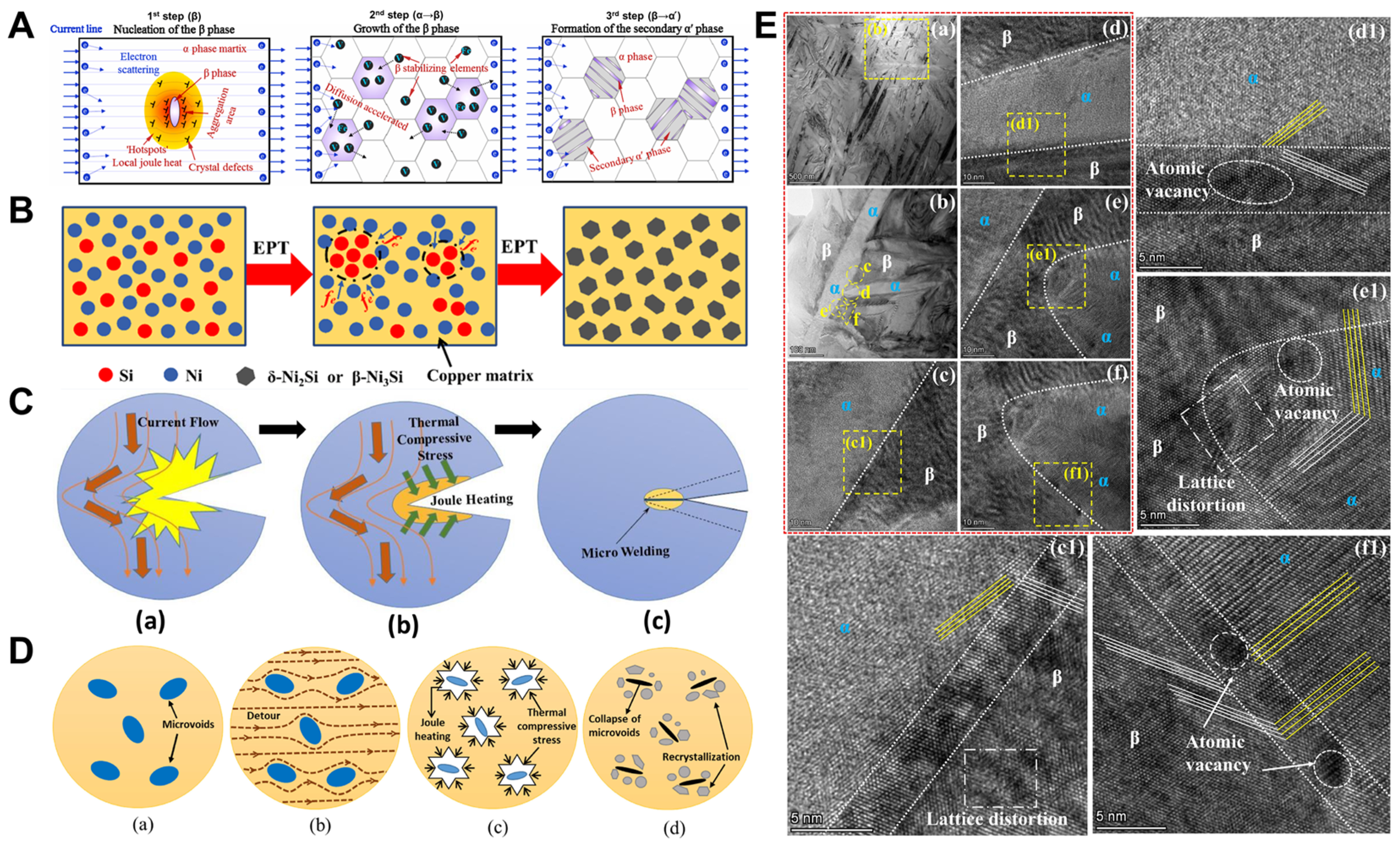
As depicted in Figure 9A, Bao and colleagues [115] hypothesized that during Electro–Assisted Micro–Compression (EAMC), the current initiates the α→β→α′ phase transition in Ti–6Al–4V alloys, where the “hot spot” effect of localized Joule heating serves as the primary driver for the nucleation of new β–phase. Zhu et al. [116] suggested that when vacancies migrate and accumulate in areas such as dislocations and grain boundaries, they turn into nucleation sites for precipitates. The kinetic energy exchange between drifting electrons and solute atoms (Ni and Si) enhances the diffusivity of the solute atoms and lowers the energy barrier that the solute atoms have to overcome during the precipitation process, thereby speeding up the formation of precipitates (Figure 9B). The application of an electrical pulse speeds up the diffusion of atoms and the movement of dislocations toward the crack, assisting in its healing. This healing phenomenon can be attributed to Joule heating and the thermal compressive stress caused by the pulsed current bypassing the crack tip (Figure 9C) [117]. In Figure 9D, the micropore collapse is caused by the local softening of the micropore edges due to Joule heating and thermocompression stress. Furthermore, EPT promotes the migration of atoms to locally recrystallize near the healing zone [118]. As shown in Figure 9E(c1,d1), Guo et al. [119] lattice distortion near the interface might be a result of atomic migration under pulse current. In Figure 9E(e1,f1), an increased presence of atomic vacancies and lattice distortions near the interface might be linked to the precipitation of the α phase in β grains and the atomic migration at the α tip during the phase transition.
To sum up, throughout the EPT procedure, the generation of Joule heating and the movement of electrons contribute to the acceleration of atom and vacancy diffusion because of increased resistivity [120,121], thereby realizing the phase transition (development to equilibrium). Furthermore, the hot–compression stress can further promote the migration of atoms around the pores and achieve the healing of the pores.
5. Effects of EPT on Texture and Recrystallization
The dissipation of residual stress through flow stress drop via pulsed current is crucial as it allows for the release of elastic forces within the material through either macroscopic or microscopic plastic deformation, driven by dislocation movement [122]. The interaction between the electroplastic effect and both thermal and non–thermal effects leads to a reduction in the material’s flow stress; this means that dislocations will reorganize, creating high–density, low–angle boundaries to mitigate stress concentrations [123,124,125]. Additionally, as the frequency of the electric pulse increases, the extent of recrystallization also rises [126], leading to the formation of a recrystallized microstructure characterized by fine, equiaxed grains, which contributes to a reduction in the strength of the material’s texture [127,128].
5.1. Electroplastic Effect
Upon the application of pulse current to the deformed alloy, there is a notable decrease in the alloy’s resistance to deformation, and its plasticity is greatly enhanced [68]. As Conrad and colleagues [44,83] have suggested, the plastic deformation, which is governed by the thermally activated movement of dislocations, along with the plastic strain experienced during the pulse, is
where is the coefficient closely associated with the density of moveable dislocations, the vibration frequency of individual dislocations, the extent of area influenced by thermal oscillations and the activation entropy. denotes the energy of activation for enthalpy, is the effective stress applied, represents the Boltzmann constant, and stands for the temperature. Conrad [45] believes that the effects produced by the pulse current, both thermal and non–thermal, primarily influence the pre–exponential factor and the activation enthalpy associated with dislocation motion. When the current passing through the conductor does not alter the thermal activation properties of dislocation movement, the rate of plastic deformation under the influence of the current is [129]
where represents the activation energy, indicates the threshold stress for the dislocation to surpass the barrier, and is an exponent not reliant on the effective stress, is the barrier spacing. Force effects (electron wind, thermal compressive stress, magnetic force, etc.) can have an effect on the , which may promote dislocations from local pinning and thus affect the plastic behavior of materials [130]. Ma et al. [131] deduced the creep model under the coupled action of force, electricity and heat:
where denotes the rate of inelastic strain, represents the energy required for activation, stands for the stress multiplier, stands for the stress, s stands for the internal variable of the average isotropic resistance to plastic flow, stands for the strain rate sensitivity, and is activation energy change caused by the current. It is observed that (i) the thermal component of the electroplastic can lessen the resistance against dislocation motion due to lattice friction and boost the frequency of dislocation oscillations, thereby reducing the energy barrier for dislocation slip; and (ii) the non–thermal dimension of the electroplastic effect is capable of modifying the local energy landscape of the dislocation core, altering how dislocations navigate obstacles and decreasing the thermal activation barriers they encounter. The synergistic influence of these elements facilitates the material’s plastic deformation, essential for flow stress drop within the sample.
5.2. Thermal and Non–Thermal Effects on Grain Boundary Migration
Annealing recrystallization nucleation can be characterized by the migration of low–angle boundaries (LABM) and the motion of high–angle boundaries (HABM) [132]. The noticeable increases in the migration rates of both low– and high–angle boundaries are due to the enhanced exchange of vacancies and individual atoms during the EPT process. Typically, the speeds at which these boundaries move (v) are described through the equation below [133,134]:
where P denotes driving pressure, M indicates the mobility of the boundary, stands for a material constant, T stands for the absolute temperature, Q represents the energy required for boundary migration, and R stands for the gas constant. In EPT, the total driving pressure is [135]
where signifies the volume energy, stands for the energy associated with grain boundaries, is predominantly linked to the thermal compressive stress resulting from Joule heat, and mainly refers to the electronic wind force. As the current density and frequency increase, M, and exhibit pronounced rises, leading to elevated stored energy levels and accelerated boundary migration. Consequently, this phenomenon promotes the initiation of twin recrystallization at comparatively reduced temperatures.
During plastic deformation, alterations in the shape and alignment of grains lead to a non–uniform grain orientation. Recrystallization initiates at points where different twinning systems intersect or through the reorganization of lattice dislocations within the twinned regions, which can produce small, recrystallized grains inducing random misorientation and another deviation along the rolling direction (RD) [136]. The Kernel Average Misorientation (KAM) serves as an indicator of the homogeneity of plastic deformation. Gao and co–authors [137] demonstrated a relationship between the density of geometrically necessary dislocations (GNDs) and the KAM value, as indicated by the subsequent equation:
where , , and correspond to the average KAM measured in radians, the scanning step size and the Burgers vector, respectively. Typically, the extent of plastic deformation increases as the value of KAM increases, and the value of KAM increases as the texture strength becomes lower.
5.3. Effects on Texture
According to Troitskii’s [138,139] study, when electrons move perpendicularly to the slip system, that is, when their path is orthogonal to dislocations on the slip plane, the plasticity of the crystal is substantially diminished. This effect is akin to the way precipitates can pin dislocations when the direction of electron flow is perpendicular to the plane defined by the dislocation and its Burgers vector, thereby impeding dislocation movement [140,141].
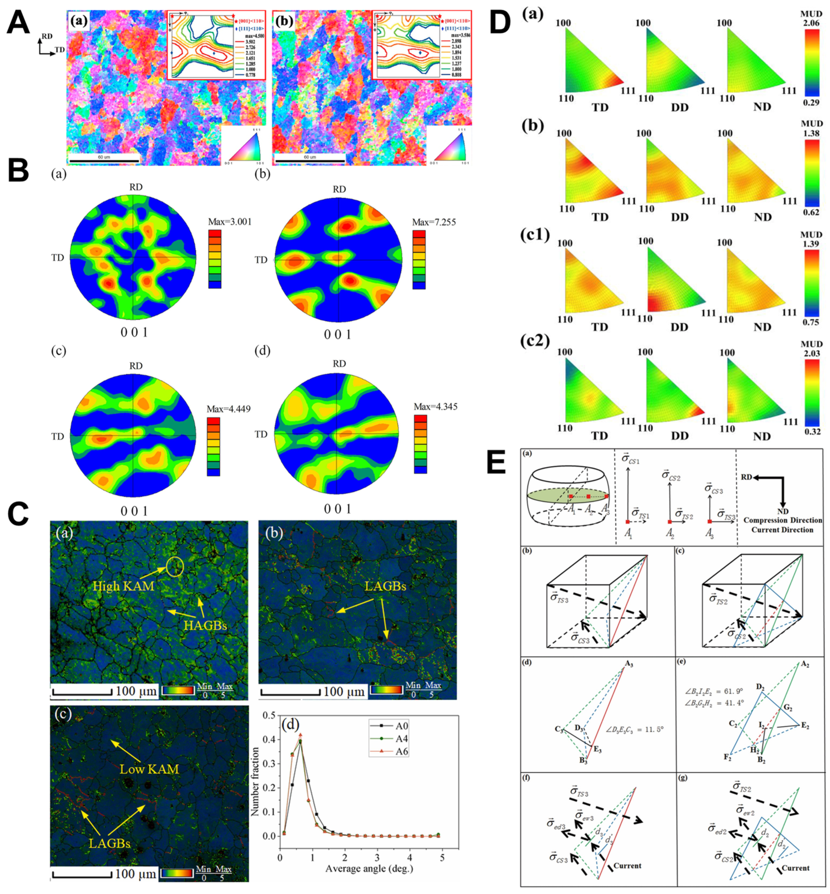
Figure 10A shows that the maximum texture strength of the cold–rolled samples after EPT decreased from 4.500 to 3.586, and the increase in the KAM value eliminated part of the stress [142]. In Figure 10B, the texture that developed post–compression at RT is solely a deformation texture due to crystal slip, with a texture strength of 7.255. This figure is significantly higher than that resulting from pulse current deformation (4.449 and 4.345). During the Electrically Assisted Microforming (EAM) compression process, the recrystallization texture prompted by the pulsed current and the deformation texture caused by crystal slip counteract each other. This interaction leads to a decrease in overall texture strength and an increase in the orientation dispersion within the grains [143].
Figure 10.
(A) The IPF and ODF maps of direction specimens (a) without treatment and (b) with EST2 treatment [142]. (B) Pole figure of samples under different conditions: (a) uncompressed; (b) compressed at 0 A/mm2; (c) compressed at 57.16 A/mm2; (d) compressed at 70.23 A/mm2 [143]. (C): KAM distributions of (a) A0 sample; (b) A4 sample; and (c) A6 sample and (d) KAM numerical statistics [144]. (D) Inverse pole figures (IPFs) of the α^′–Fe phase in the samples: (a) initial; (b) CQ + CT, (c1) EQ + ET, (c2) IPFs of γ–Fe phase in EQ + ET sample; note: ND denotes the normal direction [145]. (E) Characteristics of the external load and electron wind stress and the rotation law of the crystal grains under the coupled stress field: (a) stress state in different regions during simple compression; (b) relationship between the stress state and grain rotation at A3 in sample A during simple compression; (c) relationship between the stress state and grain rotation at A2 in sample A during simple compression; (d) stress state and grain rotation angle at A3 in sample A during simple compression; (e) stress state and grain rotation angle at A2 in sample A during simple compression; (f) coupled stress field and grain rotation at B3 in sample B during electroplastic compression; (g) coupled stress field and grain rotation at B2 in sample B during electroplastic compression [146].

In Figure 10C, Ang et al. [144] believed that dislocations annihilate, grains rotate, and subgrain boundaries increase under the action of induced current. In Figure 11B(a), a pronounced <111> texture of α’–Fe appeared in TD, whereas it was weakened after tempering and conventional quenching (CT + CQ), as shown in Figure 10D(b). Nonetheless, this <111> texture nearly vanishes after tempering and electropulse quenching (ET + EQ), with the emergence of a new <110> texture (α’–Fe) aligned with the direction of the current, as depicted in Figure 10D(c1). In addition, the <111> orientation in the majority of the γ–Fe phase in the ET + EQ specimen is also aligned parallel to the current direction (Figure 10D(c2)). This underscores the critical influence of the current on the evolution of texture, while also facilitating the rapid release of micro–residual stress without a marked decrease in dislocation density [145]. Ultimately, the texture of the slip system is enhanced through the promotion of dislocation slip, and the electric current assists in achieving a more uniform texture across the sample (Figure 10E) [146].
5.4. Effects on Recrystallization
When subjected to pulse current, the material’s structure evolves toward a state of reduced free energy, meaning the current lowers the material’s resistivity and consequently decreases its electrical energy’s free energy [147,148,149,150]. Furthermore, Qin et al. [151,152,153,154] proposed that the decrease in electrical free energy serves as the catalyst for the material’s structural transformation. Qin et al. [155,156] studied the mechanism of recrystallization of wrought metals under electric pulses and showed that the Gibbs free energy changes in wrought metals during pulse–treated recrystallization can be expressed as follows:
where denotes the total alteration in Gibbs free energy, represents the stored energy inside the deformed metal, and and represent the additional free energy introduced by the non–thermal and thermal influences of the pulse current, respectively. In line with established nucleation theory, the rate at which recrystallization nuclei form, denoted by , in the context of electric pulse treatment, can be articulated as follows:
where is a constant, represents the transition distance of the atom, represents the absolute temperature, represents the Boltzmann constant, and represents the diffusion coefficient. With the application of pulsed current, the expansion rate of the recrystallized core is described as follows:
where is the initial storage energy, stands for the initial rate of crystal nucleus growth, indicates the grain boundary diffusion coefficient, is the electron wind correlation coefficient, represents the positive coefficient, J is current density, indicates the atomic volume, is the atomic density at the grain boundary, is the width of the grain boundary, is the ideal crystal resistance, is the effective charge of the metal ion at the grain boundary, and and are the grown grain diameter and the original grain diameter, respectively. It can be seen that in the process of EPT, the non–thermal and thermal effects of pulsed current can increase the nucleation rate of recrystallization, but the grain growth is inhibited. The non–thermal and thermal effects can be simply understood as the Joule heat effect and electronic wind effect.
As shown in Figure 11A, Wang et al. [157] illustrated that with the prolongation of the high–density multiple pulse treatment (HMPT) time, the high–density dislocation cells and some entanglements disappeared, and the subcrystals preferentially merged through dislocation climbing in the localized regions with a high dislocation density. The majority of equiaxed recrystallized structures exhibit a flattened grain boundary morphology, as depicted in Figure 11A(e). New recrystallized nuclei are observed at the tri–angular intersection of grain boundaries at 120°, suggesting simultaneous nucleation and grain growth during the recrystallization process. Zhu et al. [158] confirmed that EPT has the capability to lower the activation energy for recrystallization and enhance the nucleation rate, thus facilitating the acceleration of recrystallization kinetics. Moreover, EPT facilitates the merging of subgrains and the generation of new strain–free equiaxed grains via recrystallization, as illustrated in Figure 11B. The peak of the intragranular deflection angle decreases from ~1° to ~0.5° with increasing Joule temperature. It indicates that the subgrain merges or the subgrain boundary migrates, forming a low–angle grain boundary (2~10°).
Figure 11.
(A) TEM images at various stages of the HMPT process: (a) initial state; (b–f) after HMPT 0.58 s, 1.16 s, 1.74 s, 2.32 s and 2.90 s, respectively [157]. (B) EBSD grain diagrams and recrystallization fractions of cold–rolled AZ31 magnesium alloy strip at 250 °C before and after electrical pulse and annealing treatments at different times: (a) as received; (b) electrical–pulsed for 1800 s; (c) annealed for 19,200 s [158]. (C) (a–c) Images showing grain misorientation along selected lines (L1–L3) in samples subjected to EHT at temperatures of 805, 855 and 905 °C for 5 min each; (d–f) local misorientation maps in the black spots treated with different EHT temperature at 805, 855 and 905 °C for 5 min, respectively [159]. (D) Diffusion and recrystallization mechanism of interface elements of TA1/304 composite plate under EPT [160].

The presence of a small orientation deviation peak of 1° within the black spot represents the characteristic microstructure of recrystallized grains. Consequently, the electroplating effect accelerates the recrystallization process of abnormal beta grains when compared to traditional furnace heating methods. In Figure 11C(a–c), electron wind and localized Joule heating contribute to the formation of dislocation loops or low–angle boundaries, thereby expediting phase transformation and recrystallization within the abnormal beta grain region. Notably, these defects, which induce lattice stress in the black dot region, result from dislocation interactions as depicted in Figure 11C(d–f) [159]. Ren et al. [160] proposed that, under the influence of EPT, a new undistorted grain core is generated in highly distorted regions, subsequently absorbing the surrounding deformed matrix for growth. The presence of dislocations and solute atoms at grain boundaries impedes the growth of equiaxed grains, leading to their alignment in strips and forming monolayer grains as shown in Figure 11D.
In conclusion, compared with the conventional treatment, the coupling of non–thermal and thermal effects of pulse current leads to an increase in nucleation rate. Furthermore, the increases in atomic diffusivity, dislocation arrangement and grain boundary migration promote the formation of recrystallization and texture modification. Flow stress can be reduced through plastic deformation caused by recrystallization and texture modification.
6. Finite Element Applications
The finite element model was constructed upon a set of governing equations, which encompass the dynamic coupling of principles such as the conservation of charge, Fourier’s law and equations of kinetic mechanics [161,162,163]. Pulsed current processing entails considerations of electromagnetism, electrodynamics, plastic dynamics and heat transfer [164,165]. Within the EPT process, Finite Element Simulation (FES) is predominantly employed to investigate the effects of different materials and control parameters on thermal, electrical and stress distributions within the system [166,167,168].
In the EPT process, significant features include the (i) transient stress drop during current density application, (ii) recovery of hardening behavior during current removal and (iii) long–range thermal softening [169,170,171]. A robust model must accurately capture the respective features in either mode currently applied. With the understanding of the electroplastic mechanism, the FES modeling has been realized from Joule heat to Joule heat coupled with electron wind to Joule heat coupled with electron wind based on dislocation density [172,173,174,175]. Table 1 presents the classification of constitutive models for electroplasticity. Importantly, none of the current constitutive models can accurately describe the specific process of flow stress drop using pulsed current, indicating the need for further modification.
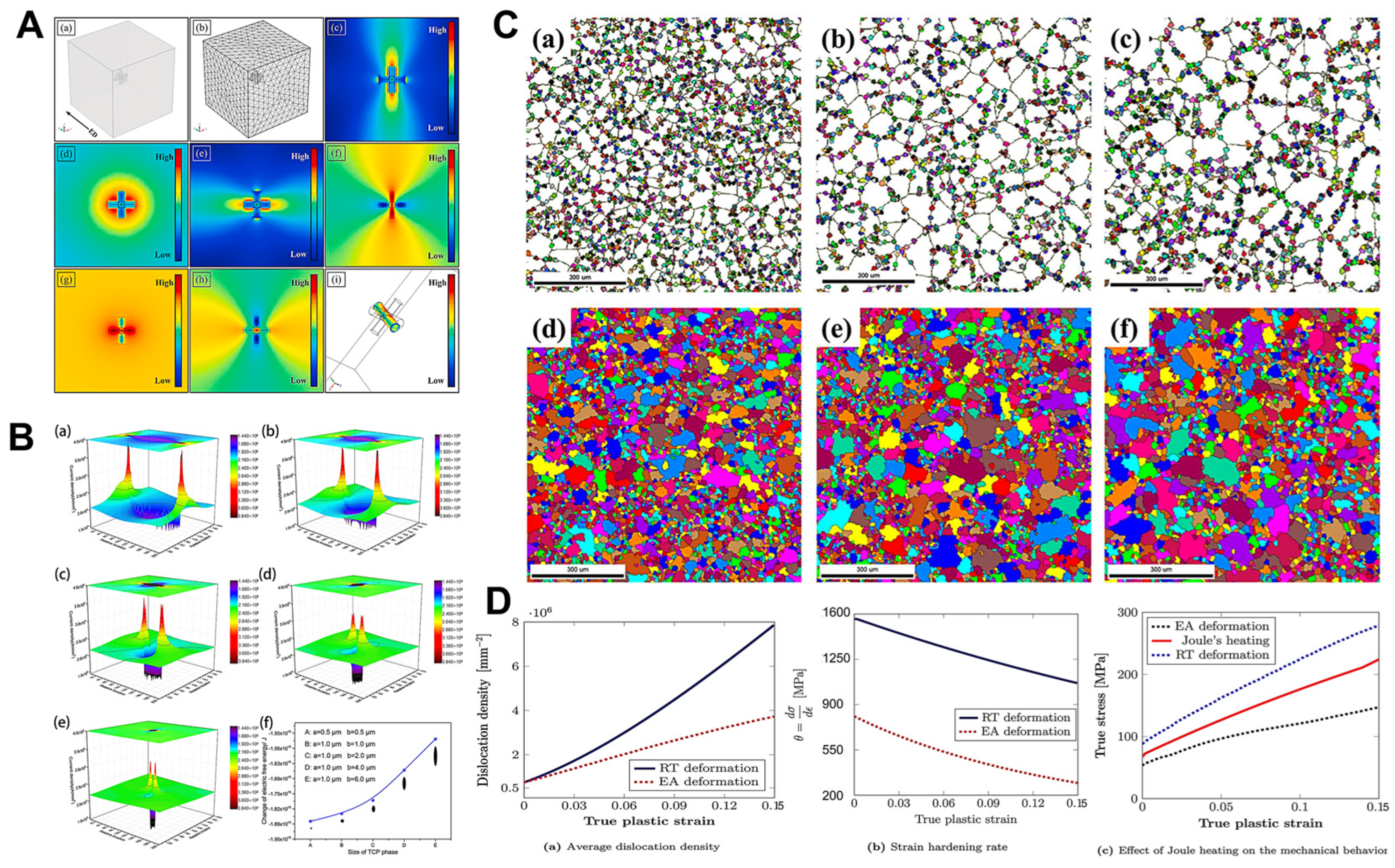
Figure 12A illustrates the matrix as a high–conductivity cube, with the untreated sample’s dislocation entanglement reduced to three mutually perpendicular, connected rods of low conductivity. Thermal compressive stress peaks at the entanglement’s pinning point, leading to its gradual disappearance and leaving only dislocations parallel to the current direction during EPT [176]. As shown in Figure 12B, Qin et al. [177] used MATLAB and the finite difference method to solve the topologically close–pack (TCP) phase model. The results reveal that the current density peaks at the tip of the TCP phase, with stronger electron winds accelerating atomic diffusion. Additionally, a reduction in size correlates with a decrease in electrical free energy. Figure 12C presents simulation and experimental results of three sets of tested recrystallized grains. Colored grains represent recrystallized grains, while white grains represent the matrix. The standard errors for all three sets of results are ±4.56%, suggesting that the recrystallization nucleation mechanism of the Al–Zn–Mg–Cu alloy is dynamic recrystallization [178]. Figure 12D showcases the simulation conducted by Tiwari et al. [169] on the changes in material mechanical behavior solely due to Joule heating, employing finite elements within a coupled electro–thermal–mechanical model. The results indicate that Joule heating can effectively reduce stress.

Table 1.
The constitutive models of the mechanical behaviors of materials under the current application.
Table 1.
The constitutive models of the mechanical behaviors of materials under the current application.
| Models | Constitutive Equation | Authors |
|---|---|---|
| Empirical models | Roh et al. [179] | |
| Kim et al. [180] | ||
| Joule heating–based models | Kronenberger et al. [181] | |
| , | Gallo et al. [182] | |
| Salandro et al. [183] | ||
| Jones [184] | ||
| Magargee et al. [185] | ||
| Zheng et al. [186] | ||
| Wang et al. [111] | ||
| Wang et al. [187] | ||
| Viscoplastic equation–based models | Conrad [44] | |
| Lee et al. [188] | ||
| Hariharan et al. [189] | ||
| Wang et al. [190] | ||
| Physically based–models | Lahiri et al. [191] | |
| Dimitrov et al. [192] | ||
| Kim et al. [193] | ||
| Liu et al. [194] | ||
| Hariharan et al. [172] |
7. Conclusion and Perspective
Controlling flow stress in metal materials through pulse current has emerged as a rapidly advancing research field, garnering increasing attention and notable progress. Reducing flow stress using EPT is a nascent area of research, fraught with numerous challenges and uncertainties, especially when compared to traditional methods like natural aging, thermal aging, vibration aging, explosion and hammering methods. This progress report presents a comprehensive overview of recent advancements in understanding the microscopic mechanisms of EPT for mitigating flow stress. Additionally, we offer an in–depth analysis covering various scales, including dislocation behavior, atomic structure, phase transitions, texture development and recrystallization processes. Through this discourse, we enhance our comprehension of how EPT relieves flow stress by examining it from the perspective of organizational structure evolution at the microscopic level. Then, we tried to isolate the various effects caused by the pulse current, and systematically illustrated each effect on the evolution of organizational structure.
Despite being in its infancy, research on flow stress drop through EPT remains highly appealing. Presently, there is a lack of comprehensive theories and models applicable to EPT, and the observation and mechanism description of the specific microscopic process of reducing flow stress under pulsed current are still unclear. The research prospect of EPT is broad, and the regular research results need to be further explored. It is important to note that future investigations into flow stress drop under EPT will need to carefully address several challenges and issues. From our perspective, the most significant of these issues are summarized as follows:
- As for the microscopic mechanism of flow stress drop under EPT, it is generally believed that the Joule thermal effect, electronic wind effect and electroplastic effect have the main influence on the flow stress drop compared with skin effect, magnetostriction effect and pinch effect. Although the electroplastic effect has been widely recognized, the underlying mechanism related to the electric wind force has been controversial, and most studies have difficulty in separating these effects.
- Currently, several mechanisms have been proposed to explain the drop of flow stress through EPT: (i) Joule heat and electron wind can promote the migration of dislocations and carry out the rearrangement of dislocations. During the climbing, dislocation annihilation dominates, thereby reducing the dislocation density and flow stress. (ii) The electroplastic and Joule thermal effects decrease the frictional resistance within the dislocation lattice, thereby lowering the flow stress of the material. Once the flow stress drops below the initial residual stress level, the material undergoes plastic deformation, leading to residual stress reduction. (iii) The coupling of non–thermal and thermal effects induced by pulse current promotes atomic diffusion, dislocation rearrangement and grain boundary migration, leading to plastic deformation and flow stress drop.
- The electronic wind coefficient Ked calculated according to Equations (6)–(8) yields values on the order of 10−17, 10−16 and 10−15 Nm/A, respectively. In contrast, experimental results yield Ked values on the order of 10−12 Nm/A [44,45,195]. This huge discrepancy between theoretical and experimental results is something that electronic wind models have failed to address for years. The model of electronic wind power needs further revision.
- We believe that multiscale computation is the future direction of the microscopic mechanism of flow stress drop under EPT. First–principle calculations reveal that charge imbalances near defects weaken atomic bonding under electric current [196]. Machine learning can further be used to calculate the macroscopic dislocation density. Multi–scale calculation combined with numerical analysis and finite element simulation can better describe the specific microscopic process of material flow stress drop under electric current.
In summary, in this burgeoning field of research, the exemplary instances provided for the various effects on the evolution of organizational structures in this progress report may be constrained by their brevity. It is conceivable that the drop of flow stress under EPT needs to be modified and improved in theory and model. In future work, we should consider how to further clarify the relationship between the material structure, performance parameters and the flow stress drop under EPT. Additionally, the influences of the pulse current waveform, frequency and other parameters also need to be further explored and analyzed. We posit that this progress report holds significant implications for the reduction of flow stress through EPT and the enhancement of mechanical properties in metal materials.
Funding
This research was funded by [National Natural Science Foundation of China] grant number [52375457, 52205490]. And The APC was funded by [No. 52375457].
Data Availability Statement
No data were used for the research described in the article.
Conflicts of Interest
The authors declare that they have no known competing financial interests or personal relationships that could have appeared to influence the work reported in this paper.
References
- Tabatabaeian, A.; Ghasemi, A.R.; Shokrieh, M.M.; Marzbanrad, B.; Baraheni, M.; Fotouhi, M. Residual stress in engineering materials: A review. Adv. Eng. Mater. 2022, 24, 2100786. [Google Scholar] [CrossRef]
- Withers, P. Residual stress and its role in failure. Rep. Prog. Phys. 2007, 70, 2211. [Google Scholar] [CrossRef]
- Withers, P.; Turski, M.; Edwards, L.; Bouchard, P.; Buttle, D. Recent advances in Residual stress measurement. Int. J. Press. Vessels Pip. 2008, 85, 118–127. [Google Scholar] [CrossRef]
- Finch, L. Residual Strains in Plastically Deformed Mild Steels. Nature 1950, 166, 508–509. [Google Scholar] [CrossRef]
- Greenough, G. Residual strains in plastically deformed mild steels. Nature 1950, 166, 509–510. [Google Scholar] [CrossRef]
- Wood, W.; Dewsnap, N. Internal stresses in metals. Nature 1948, 161, 682–683. [Google Scholar] [CrossRef]
- Garrod, R. Residual Lattice Strains in Mild Steel. Nature 1950, 165, 241–242. [Google Scholar] [CrossRef]
- Sowerby, R.; Uko, D.; Tomita, Y. A review of certain aspects of the Bauschinger effect in metals. Mater. Sci. Eng. 1979, 41, 43–58. [Google Scholar] [CrossRef]
- Gumao, M. Generation and Countermeasures of Residual Stress; Machinery Industry Press: Beijing, China, 1983. [Google Scholar]
- Seeger, A.; Donth, H.; Kochendörfer, A. Theorie der Versetzungen in eindimensionalen Atomreihen. Z. Für Phys. 1953, 134, 173–193. [Google Scholar] [CrossRef]
- Ma, A.; Cheng, J.; Wei, D.; Li, Q.; Fang, F.; Li, Z. Experiments and numerical analyses on splitting fracture of wire under multi–pass drawing. Eng. Fail. Anal. 2022, 134, 106035. [Google Scholar] [CrossRef]
- Oda, S.; Tanaka, S.-I. Effect of local texture and residual stress on the bendability of extruded 6000–series Al alloy profiles. Mater. Sci. Eng. A 2022, 829, 142167. [Google Scholar] [CrossRef]
- Wu, D.; Lv, H.; Wang, H.; Yu, J. Surface micro–morphology and residual stress formation mechanisms of near–net–shaped blade produced by low–plasticity ultrasonic rolling strengthening process. Mater. Des. 2022, 215, 110513. [Google Scholar] [CrossRef]
- Karasz, E.K.; Taylor, J.; Autenrieth, D.M.; Reu, P.; Johnson, K.; Melia, M.; Noell, P. Measuring the residual stress and Stress Corrosion Cracking Susceptibility of Additively Manufactured 316L by ASTM G36–94. Corrosion 2022, 78, 3–12. [Google Scholar] [CrossRef] [PubMed]
- Li, L.; Wu, M. Research on the residual stress of the Machined Surface of Cutting Superalloy under High Pressure Cooling. Integr. Ferroelectr. 2022, 226, 42–57. [Google Scholar] [CrossRef]
- Zhang, Z.; Sui, M.; Li, C.; Zhou, Z.; Liu, B.; Chen, Y.; Said, Z.; Debnath, S.; Sharma, S. residual stress of grinding cemented carbide using MoS2 nano–lubricant. Int. J. Adv. Manuf. Technol. 2022, 119, 5671–5685. [Google Scholar] [CrossRef]
- Fan, K.; Liu, D.; Zhang, X.; Liu, D.; Zhao, W.; Yang, J.; Ma, A.; Li, M.; Qi, Y.; Xiang, J.; et al. Effect of residual stress induced by ultrasonic surface rolling on fretting fatigue behaviors of Ti–6Al–4V alloy. Eng. Fract. Mech. 2022, 259, 108150. [Google Scholar] [CrossRef]
- Moradi, A.; Heidari, A.; Amini, K.; Aghadavoudi, F.; Abedinzadeh, R. The effect of shot peening time on mechanical properties and residual stress in Ti–6Al–4V alloy. Metall. Res. Technol. 2022, 119, 401. [Google Scholar] [CrossRef]
- Srivastava, M.; Hloch, S.; Krejci, L.; Chattopadhyaya, S.; Gubeljak, N.; Milkovic, M. Utilizing the water hammer effect to enhance the mechanical properties of AISI 304 welded joints. Int. J. Adv. Manuf. Technol. 2022, 119, 2317–2328. [Google Scholar] [CrossRef]
- Šarga, P.; Brezinová, J.; Viňáš, J.; Pástor, M.; Brezina, J. Impact of Cladding Technology on residual stresses within the Renovation of High Pressure Die Casting Molds. Metals 2022, 12, 388. [Google Scholar] [CrossRef]
- Samuel, A.; Prabhu, K.N. Residual stress and Distortion during Quench Hardening of Steels: A Review. J. Mater. Eng. Perform. 2022, 31, 5161–5188. [Google Scholar] [CrossRef]
- Khalaf, H.I.; Al–Sabur, R.; Abdullah, M.E.; Kubit, A.; Derazkola, H.A. Effects of Underwater friction stir Welding heat generation on residual stress of AA6068–T6 Aluminum Alloy. Materials 2022, 15, 2223. [Google Scholar] [CrossRef]
- Guo, J.; Fu, H.; Pan, B.; Kang, R. Recent progress of residual stress measurement methods: A review. Chin. J. Aeronaut. 2021, 34, 54–78. [Google Scholar] [CrossRef]
- Wei, P.; Hua, P.; Xia, M.; Yan, K.; Lin, H.; Yi, S.; Lu, J.; Ren, F.; Sun, Q. Bending fatigue life enhancement of NiTi alloy by pre–strain warm surface mechanical attrition treatment. Acta Mater. 2022, 240, 118269. [Google Scholar] [CrossRef]
- Chu, Q.; Xia, T.; Zhao, P.; Zhang, M.; Zheng, J.; Yan, F.; Cheng, P.; Yan, C.; Liu, C.; Luo, H. Interfacial investigation of explosion–welded Al/steel plate: The microstructure, mechanical properties and residual stresses. Mater. Sci. Eng. A 2022, 833, 142525. [Google Scholar] [CrossRef]
- Robinson, J.S.; Hossain, M.S.; Truman, C.E. residual stresses in the aluminium alloy 2014A subject to PAG quenching and vibratory stress relief. J. Strain. Anal. Eng. Des. 2022, 57, 167–176. [Google Scholar] [CrossRef]
- Zeng, Z.; Zhang, C.; Lin, B.; Yang, J.; Liu, X.; Wang, T.; Li, J.; Lin, J.; Dai, Y. Eddy Current testing of residual stress state in aluminum alloy. IEEE Trans. Instrum. Meas. 2021, 70, 6007208. [Google Scholar] [CrossRef]
- Yi, R.; Chen, C.; Shi, C.; Li, Y.; Li, H.; Ma, Y. Research advances in residual thermal stress of ceramic/metal brazes. Ceram. Int. 2021, 47, 20807–20820. [Google Scholar] [CrossRef]
- Raftar, O.R.; Kaveh, M.; Khajehzadeh, M.; Rahimi, A.; Razfar, M.R. Nano–lubricant influence on surface residual stresses in hard milling. Proc. Inst. Mech. Eng. Part E J. Process. Mech. Eng. 2021, 235, 1499–1510. [Google Scholar] [CrossRef]
- Mirkoohi, E.; Li, D.; Garmestani, H.; Liang, S.Y. Residual stress modeling considering microstructure evolution in metal additive manufacturing. J. Manuf. Process. 2021, 68, 383–397. [Google Scholar] [CrossRef]
- Baumann, M.; Selbmann, R.; Dobecki, M.; Krausel, V.; Reimers, W.; Bergmann, M. Specific influencing of forming–induced residual stresses during wire drawing. Forsch. Ingenieurwesen 2021, 85, 773–781. [Google Scholar] [CrossRef]
- Liu, H.; Zhao, G.; Liu, C.; Zuo, L. Artificial aging precipitation behavior of 6000 series alloys naturally aged and pre–aged. Trans. Mater. Heat. Treat. 2008, 29, 74–78. [Google Scholar]
- Nazari, F.; Honarpisheh, M.; Zhao, H. Effect of stress relief annealing on microstructure, mechanical properties, and residual stress of a copper sheet in the constrained groove pressing process. Int. J. Adv. Manuf. Technol. 2019, 102, 4361–4370. [Google Scholar] [CrossRef]
- Gao, H.; Li, X.; Li, B.; Wu, Q.; Ma, Y.; Jian, X.; Song, H.; Chen, S. Residual stress and microstructure of Ti6Al4V treated by thermal–vibratory stress relief process. J. Mater. Res. Technol. 2022, 18, 5161–5181. [Google Scholar] [CrossRef]
- Zhu, K.; Xiong, B.; Li, X.; Zhang, Y.; Li, Z.; Li, Y.; Wen, K.; Yan, L. Finite element simulation on residual stress during immersion quenching and pre–stretching of Al7055 thick plates. Mater. Res. Express 2022, 9, 026525. [Google Scholar] [CrossRef]
- Gkatzogiannis, S. Finite Element Simulation of Residual Stresses from Welding and High Frequency Hammer Peening; KIT Scientific Publishing: Karlsruhe, Germany, 2022. [Google Scholar]
- Ostapenko, M.G.; Semin, V.O.; D’Yachenko, F.A.; Neiman, A.A.; Meisner, L.L. Structure and residual stress distribution in TiNi substrate after fabrication of surface alloy using electron–beam treatments. Acta Mater. 2022, 231, 117893. [Google Scholar] [CrossRef]
- Zhang, X.; Xiang, S.; Yi, K.; Guo, J. Controlling the residual stress in Metallic Solids by Pulsed Electric Current. Acta Metall. Sin. 2022, 58, 581–598. [Google Scholar]
- Takemoto, R.; Nagata, M.; Mizubayashi, H. Effects of passing electric current on the elastic property of amorphous Cu50Zr50 and Cu50Ti50. Acta Mater. 1996, 44, 2787–2795. [Google Scholar] [CrossRef]
- Okazaki, K.; Kagawa, M.; Conrad, H. A study of the electroplastic effect in metals. Scr. Metall. 1978, 12, 1063–1068. [Google Scholar] [CrossRef]
- Okazaki, K.; Kagawa, M.; Conrad, H. Additional results on the electroplastic effect in metals. Scr. Metall. 1979, 13, 277–280. [Google Scholar] [CrossRef]
- Okazaki, K.; Kagawa, M.; Conrad, H. Effects of strain rate, temperature and interstitial content on the electroplastic effect in titanium. Scr. Metall. 1979, 13, 473–477. [Google Scholar] [CrossRef]
- Conrad, H.; Okazaki, K. A Study of the Electroplastic Effect in Metals; Department of Metallurgical Engineering and Materials Science, Kentucky University: Lexington, KY, USA, 1979. [Google Scholar]
- Conrad, H. Electroplasticity in metals and ceramics. Mater. Sci. Eng. A 2000, 287, 276–287. [Google Scholar] [CrossRef]
- Conrad, H. Thermally activated plastic flow of metals and ceramics with an electric field or current. Mater. Sci. Eng. A 2002, 322, 100–107. [Google Scholar] [CrossRef]
- Baeurle, S.A.; Hotta, A.; Gusev, A.A. A new semi–phenomenological approach to predict the stress relaxation behavior of thermoplastic elastomers. Polymer 2005, 46, 4344–4354. [Google Scholar] [CrossRef]
- Fei, W.; Hu, M.; Yao, C. Thermal expansion and thermal mismatch stress relaxation behaviors of SiC whisker reinforced aluminum composite. Mater. Chem. Phys. 2003, 77, 882–888. [Google Scholar] [CrossRef]
- Chen, J.; Jiang, J.; Zhen, L.; Shao, W. Stress relaxation behavior of an Al–Zn–Mg–Cu alloy in simulated age–forming process. J. Mater. Process. Technol. 2014, 214, 775–783. [Google Scholar] [CrossRef]
- Manson, S.S. Behavior of Materials under Conditions of Thermal Stress; National Advisory Committee for Aeronautics, District of Columbia: Columbia, SC, USA, 1953.
- Morland, L.W.; Lee, E. Stress analysis for linear viscoelastic materials with temperature variation. Trans. Soc. Rheol. 1960, 4, 233–263. [Google Scholar] [CrossRef]
- Li, C.; Zhang, Y.; Xu, J.; Li, F. Influence of pulse current on bending stress relaxation of nanocrystalline Ni foil. Results Phys. 2019, 13, 102182. [Google Scholar] [CrossRef]
- Zhan, L.; Ma, Z.; Zhang, J.; Tan, J.; Yang, Z.; Li, H. Stress relaxation ageing behaviour and constitutive modelling of a 2219 aluminium alloy under the effect of an electric pulse. J. Alloys Compd. 2016, 679, 316–323. [Google Scholar] [CrossRef]
- Yang, Y.; Qin, R.; Dong, Y.; Wang, J.; Ye, C. Crystal plasticity modeling of electropulsing induced plasticity in metals. Int. J. Plast. 2023, 171, 103828. [Google Scholar] [CrossRef]
- Conrad, H.; Yang, D. Effect of DC electric field on the tensile deformation of ultrafine–grained 3Y–TZP at 1450–1600 °C. Acta Mater. 2007, 55, 6789–6797. [Google Scholar] [CrossRef]
- Liang, C.-L.; Lin, K.-L. The microstructure and property variations of metals induced by electric current treatment: A review. Mater. Charact. 2018, 145, 545–555. [Google Scholar] [CrossRef]
- Kocks, U. Laws for work–hardening and low–temperature creep. J. Eng. Mater. Technol. 1976, 98, 76. [Google Scholar] [CrossRef]
- Mecking, H.; Kocks, U. Kinetics of flow and strain–hardening. Acta Metall. 1981, 29, 1865–1875. [Google Scholar] [CrossRef]
- Liu, J.; Zhang, K. Influence of electric current on superplastic deformation mechanism of 5083 aluminium alloy. Mater. Sci. Technol. 2016, 32, 540–546. [Google Scholar] [CrossRef]
- HajyAkbary, F.; Sietsma, J.; Böttger, A.J.; Santofimia, M.J. An improved X-ray diffraction analysis method to characterize dislocation density in lath martensitic structures. Mater. Sci. Eng. A 2015, 639, 208–218. [Google Scholar] [CrossRef]
- Williamson, G.; Hall, W. X-ray line broadening from filed aluminium and wolfram. Acta Metall. 1953, 1, 22–31. [Google Scholar] [CrossRef]
- Ungár, T.; Borbély, A. The effect of dislocation contrast on X-ray line broadening: A new approach to line profile analysis. Appl. Phys. Lett. 1996, 69, 3173–3175. [Google Scholar] [CrossRef]
- Revesz, A.; Ungár, T.; Borbely, A.; Lendvai, J. Dislocations and grain size in ball–milled iron powder. Nanostruct. Mater. 1996, 7, 779–788. [Google Scholar] [CrossRef]
- Zhou, C.; Zhan, L.; Li, H. Improving creep age formability of an Al–Cu–Li alloy by electropulsing. J. Alloys Compd. 2021, 870, 159482. [Google Scholar] [CrossRef]
- Zhou, C.; Zhan, L.; Li, H.; Chen, F.; Liu, G.; Yan, D. Mechanism of an acceleration in T1 precipitation kinetics in an Al–Cu–Li alloy by electropulsing. Vacuum 2021, 194, 110558. [Google Scholar] [CrossRef]
- Sheng, Y.; Hua, Y.; Wang, X.; Zhao, X.; Chen, L.; Zhou, H.; Wang, J.; Berndt, C.C.; Li, W. Application of high–density electropulsing to improve the performance of metallic materials: Mechanisms, microstructure and properties. Materials 2018, 11, 185. [Google Scholar] [CrossRef] [PubMed]
- Korhonen, M.A.; Paszkiet, C.; Li, C.Y. Mechanisms of thermal stress relaxation and stress-induced voiding in narrow aluminum-based metallizations. J. Appl. Phys. 1991, 69, 8083–8091. [Google Scholar] [CrossRef]
- Wang, Y.; Xia, L.; Zhang, H.; Cao, Y.; Pan, A.; Wu, W. The serration behavior and mechanical properties of Al0.1CoCrFeNi high–entropy alloy under coupled electron–heat field. J. Alloys Compd. 2022, 898, 162789. [Google Scholar] [CrossRef]
- Rudolf, C.; Goswami, R.; Kang, W.; Thomas, J. Effects of electric current on the plastic deformation behavior of pure copper, iron, and titanium. Acta Mater. 2021, 209, 116776. [Google Scholar] [CrossRef]
- Xiao, H.; Xia, X.; Huang, S.; Chen, Q.; Zhao, G.; Zhao, Z.; Wang, Y.; Chai, S.; Peng, F. Study on mechanical behavior and microstructure evolution of Al–Mg–Li alloy during electropulsing assisted uniaxial tensile. J. Alloys Compd. 2022, 900, 163425. [Google Scholar] [CrossRef]
- Han, C.; Ye, F.; Du, H.; Liu, B.; Liang, Y.; Li, H.; Li, H. Improved ductility of Fe–6.5 wt% Si alloy under electropulsing tension. Mater. Sci. Eng. A 2022, 851, 143639. [Google Scholar] [CrossRef]
- Caillard, D.; Martin, J. Thermally activated mechanisms in crystal plasticity. MRS Bull. 2005, 30, 318–320. [Google Scholar]
- Garay, J.E.; Anselmi–Tamburini, U.; Munir, Z.A. Enhanced growth of intermetallic phases in the Ni–Ti system by current effects. Acta Mater. 2003, 51, 4487–4495. [Google Scholar] [CrossRef]
- Baker, S.P.; Joo, Y.-C.; Knauß, M.P.; Arzt, E. Electromigration damage in mechanically deformed Al conductor lines: Dislocations as fast diffusion paths. Acta Mater. 2000, 48, 2199–2208. [Google Scholar] [CrossRef]
- Salandro, W.A.; Jones, J.J.; Bunget, C.; Mears, L.; Roth, J.T. Electrically Assisted Forming: Modeling and Control; Springer: Berlin/Heidelberg, Germany, 2014. [Google Scholar]
- Zhang, X.; Li, H.; Zhan, M.; Shao, G.; Ma, P. Extraordinary effect of the δ phase on the electrically–assisted deformation responses of a Ni–based superalloy. Mater. Charact. 2018, 144, 597–604. [Google Scholar] [CrossRef]
- Zhang, X.; Li, H.; Zhan, M. Mechanism for the macro and micro behaviors of the Ni–based superalloy during electrically–assisted tension: Local Joule heating effect. J. Alloys Compd. 2018, 742, 480–489. [Google Scholar] [CrossRef]
- Liu, Y.; Meng, B.; Du, M.; Wan, M. Electroplastic effect and microstructural mechanism in electrically assisted deformation of nickel–based superalloys. Mater. Sci. Eng. A 2022, 840, 142975. [Google Scholar] [CrossRef]
- Zhang, H.; Zhang, X. Softening behavior of Al–Zn–Mg alloys with different strengthening mechanisms in a coupled field. Mater. Sci. Eng. A 2020, 771, 138582. [Google Scholar] [CrossRef]
- Shan, Z.; Bai, J.; Fan, J.; Wu, H.; Zhang, H.; Zhang, Q.; Wu, Y.; Li, W.; Dong, H.; Xu, B. Exceptional mechanical properties of AZ31 alloy wire by combination of cold drawing and EPT. J. Mater. Sci. Technol. 2020, 51, 111–118. [Google Scholar] [CrossRef]
- Chen, K.; Zhan, L.; Xu, Y.; Liu, Y. Effect of pulsed current density on creep–aging behavior and microstructure of AA7150 aluminum alloy. J. Mater. Res. Technol. 2020, 9, 15433–15441. [Google Scholar] [CrossRef]
- Zhang, M.; Wang, W.; Zhang, J.; Liu, C.; Wang, Z.; Wan, J.; Zhao, H. The Recovery Behavior of AZ31B Magnesium Alloy Stimulated by Electropulsing Treatment and Heat Treatment. J. Mater. Eng. Perform. 2022, 31, 8346–8354. [Google Scholar] [CrossRef]
- Troitskii, O.A.; Likhtman, V.I. The anisotropy of the action of electron and γ radiation on the deformation of zinc single crystals in the brittle state. Sov. Phys. Dokl. 1963, 8, 91. [Google Scholar]
- Kravchenko, V.Y. Effect of directed electron beam on moving dislocations. Sov. Phys. JETP 1967, 24, 1135–1142. [Google Scholar]
- Klimov, K.; Shnyrev, G.; Novikov, I. On electroplasticity of metals. Dok. Akad. Nauk SSSR 1974, 219, 323–324. [Google Scholar]
- Klimov, K.M.; Shnyrev, G.D.; Novikov, I.I. ‘Electroplasticity’ of metals. Sov. Phys. Dokl. 1975, 19, 787–788. [Google Scholar]
- Roshchupkin, A.; Miloshenko, V.; Kalinin, V. The electron retardation of dislocations in metals. Fiz. Tverd. Tela 1979, 21, 909–910. [Google Scholar]
- Nam, S.-W.; Chung, H.-S.; Lo, Y.C.; Qi, L.; Li, J.; Lu, Y.; Johnson, A.C.; Jung, Y.; Nukala, P.; Agarwal, R. Electrical wind force–driven and dislocation–templated amorphization in phase–change nanowires. Science 2012, 336, 1561–1566. [Google Scholar] [CrossRef] [PubMed]
- Krishnaswamy, H.; Tiwari, J.; Amirthalingam, M. Revisiting electron–wind effect for electroplasticity: A critical interpretation. Vacuum 2024, 221, 112937. [Google Scholar] [CrossRef]
- Zhou, C.; Zhan, L.; Liu, C.; Huang, M. Insights into electron wind force by a helical dislocation reconfiguration. iScience 2023, 26, 106870. [Google Scholar] [CrossRef]
- Troitskii, O. Pressure shaping by the application of a high energy. Mater. Sci. Eng. 1985, 75, 37–50. [Google Scholar] [CrossRef]
- Huang, Z.; Cen, Q.; Li, Z.; Wu, Y.; Zou, L. Influence of the electric current pulse with different pulse width on the eutectoid microstructure of hypoeutectic Fe–C alloys. Adv. Mat. Res. 2014, 852, 208–213. [Google Scholar] [CrossRef]
- Zhu, R.; Liu, J.; Tang, G.; Shi, S.-Q.; Fu, M. Properties, microstructure and texture evolution of cold rolled Cu strips under electropulsing treatment. J. Alloys Compd. 2012, 544, 203–208. [Google Scholar] [CrossRef]
- Frank, F.; Read, W., Jr. Multiplication processes for slow moving dislocations. Phys. Rev. 1950, 79, 722–723. [Google Scholar] [CrossRef]
- Xiang, S.; Zhang, X. Dislocation structure evolution under electroplastic effect. Mater. Sci. Eng. A 2019, 761, 138026. [Google Scholar] [CrossRef]
- Zhou, C.; Zhan, L.; Li, H.; Liu, C.; Xu, Y.; Ma, B.; Yang, Y.; Huang, M. Dislocation reconfiguration during creep deformation of an Al–Cu–Li alloy via electropulsing. J. Mater. Sci. Technol. 2022, 130, 27–34. [Google Scholar] [CrossRef]
- Zhang, H.; Zhang, C.; Han, B.; Gao, K.; Fang, R.; Deng, N.; Zhou, H. Static recrystallization microstructure evolution in a cold–deformed Ni–based superalloy during electropulsing treatment. Crystals 2020, 10, 884. [Google Scholar] [CrossRef]
- Zhao, Z.; Wang, G.; Hou, H.; Han, B.; Zhang, Y.; Zhang, N. Influence of high–energy pulse current on the mechanical properties and microstructures of Ti–6Al–4V alloy. J. Mater. Eng. Perform. 2017, 26, 5146–5153. [Google Scholar] [CrossRef]
- Liang, C.-L.; Lin, K.-L. The amorphous interphase formed in an intermetallic–free Cu/Sn couple during early stage electromigration. Scr. Mater. 2018, 155, 58–62. [Google Scholar] [CrossRef]
- Liao, Y.-H.; Chen, C.-H.; Liang, C.-L.; Lin, K.-L.; Wu, A.T. A comprehensive study of electromigration in pure Sn: Effects on crystallinity, microstructure, and electrical property. Acta Mater. 2020, 200, 200–210. [Google Scholar] [CrossRef]
- Wang, H.; Kou, R.; Harrington, T.; Vecchio, K.S. Electromigration effect in Fe–Al diffusion couples with field–assisted sintering. Acta Mater. 2020, 186, 631–643. [Google Scholar] [CrossRef]
- Zhang, X.; Li, H.; Zhan, M.; Zheng, Z.; Gao, J.; Shao, G. Electron force–induced dislocations annihilation and regeneration of a superalloy through electrical in–situ transmission electron microscopy observations. J. Mater. Sci. Technol. 2020, 36, 79–83. [Google Scholar] [CrossRef]
- Xu, Z.; Guo, P.; Peng, L.; Lai, X. Electroplasticity mechanism study based on dislocation behavior of Al6061 in tensile process. J. Alloys Compd. 2022, 910, 164890. [Google Scholar]
- Waryoba, D.; Islam, Z.; Reutzel, T.; Haque, A. Electro–strengthening of the additively manufactured Ti–6Al–4V alloy. Mater. Sci. Eng. A 2020, 798, 140062. [Google Scholar] [CrossRef]
- Li, X.; Turner, J.; Bustillo, K.; Minor, A.M. In situ transmission electron microscopy investigation of electroplasticity in single crystal nickel. Acta Mater. 2022, 223, 117461. [Google Scholar] [CrossRef]
- Stepanov, G.; Babutskii, A. Effect of electric current on stress relaxation in metal. Strength Mater. 1996, 28, 125–128. [Google Scholar] [CrossRef]
- Zhang, W.; Sui, M.-L.; Zhou, Y.; He, G.; Guo, J.; Li, D. Electropulsing–induced evolution of microstructures in materials. Acta Metall. Sin. 2003, 39, 1009–1018. [Google Scholar] [CrossRef]
- Dolinsky, Y.; Elperin, T. Thermodynamics of phase transitions in current–carrying conductors. Phys. Rev. B 1993, 47, 14778–14785. [Google Scholar] [CrossRef]
- Klinger, L.; Levin, L.; Srolovitz, D. Interface diffusion under an electric field. Interface evolution. Mater. Sci. Forum 1996, 207–209, 109–112. [Google Scholar] [CrossRef]
- Lu, W.; Zhang, X.; Qin, R. Electropulsing–induced strengthening of steel at high temperature. Philos. Mag. Lett. 2014, 94, 688–695. [Google Scholar] [CrossRef]
- Kino, T.; Endo, T.; Kawata, S. Deviations from Matthiessen’s rule of the electrical resistivity of dislocations in aluminum. J. Phys. Soc. Jpn. 1974, 36, 698–705. [Google Scholar] [CrossRef]
- Wang, X.; Xu, J.; Jiang, Z.; Zhu, W.-L.; Shan, D.; Guo, B.; Cao, J. Size effects on residual stress behavior during electrically–assisted micro–tension in a magnesium alloy AZ31. Mat. Sci. Eng. A Struct. 2016, 659, 215–224. [Google Scholar] [CrossRef]
- Cao, C.; Mücke, R.; Guillon, O. Effect of AC field on uniaxial viscosity and sintering stress of ceria. Acta Mater. 2020, 182, 77–86. [Google Scholar] [CrossRef]
- Xiao, A.; Huang, C.; Yan, Z.; Cui, X.; Wang, S. Improved forming capability of 7075 aluminum alloy using electrically assisted electromagnetic forming. Mater. Charact. 2022, 183, 111615. [Google Scholar] [CrossRef]
- Tang, D.; Zhou, B.; Cao, H.; He, G. Thermal stress relaxation behavior in thin films under transient laser-pulse heating. J. Appl. Phys. 1993, 73, 3749–3752. [Google Scholar] [CrossRef]
- Bao, J.; Chen, W.; Bai, J.; Xu, J.; Shan, D.; Guo, B. Local softening deformation and phase transformation induced by electric current in electrically–assisted micro–compression of Ti–6Al–4V alloy. Mater. Sci. Eng. A 2022, 831, 142262. [Google Scholar] [CrossRef]
- Zhu, J.; Lin, Y.; Liu, S.; Lin, X.; Wang, G. Electropulsing aging treatment of Cu–Ni–sheet for microforming. Adv. Eng. Mater. 2021, 23, 2100249. [Google Scholar] [CrossRef]
- Kumar, A.; Paul, S.K. Healing of fatigue crack in steel with the application of pulsed electric current. Materialia 2020, 14, 100906. [Google Scholar] [CrossRef]
- Kumar, A.; Paul, S.K. Improvement in tensile properties of pre–strained steel specimen by applying pulsed electric current. Materialia 2021, 15, 100960. [Google Scholar] [CrossRef]
- Guo, H.; Liu, P.; Qin, X.; Song, Y.; Qian, D.; Xie, L.; Wang, L.; Zhang, L.-C.; Hua, L. Electroshock treatment dependent microstructural evolution and mechanical properties of near–β titanium alloy manufactured by directed energy deposition. Mater. Des. 2021, 212, 110286. [Google Scholar] [CrossRef]
- Lu, Y.-D.; He, X.-Q.; En, Y.-F.; Wang, X.; Zhuang, Z.-Q. Polarity effect of electromigration on intermetallic compound formation in SnPb solder joints. Acta Mater. 2009, 57, 2560–2566. [Google Scholar] [CrossRef]
- Yang, K.; Zhang, Z.; Zhao, H.; Yang, B.; Zhong, B.; Chen, N.; Song, J.; Chen, C.; Tang, D.; Zhu, J.; et al. Orientation independent heat transport characteristics of diamond/copper interface with ion beam bombardment. Acta Mater. 2021, 220, 117283. [Google Scholar] [CrossRef]
- Jeong, K.; Jin, S.-W.; Kang, S.-G.; Park, J.-W.; Jeong, H.-J.; Hong, S.-T.; Cho, S.H.; Kim, M.-J.; Han, H.N. Athermally enhanced recrystallization kinetics of ultra–low carbon steel via electric current treatment. Acta Mater. 2022, 232, 117925. [Google Scholar] [CrossRef]
- Jiang, Y.; Tang, G.; Shek, C.; Liu, W. Microstructure and texture evolution of the cold–rolled AZ91 magnesium alloy strip under electropulsing treatment. J. Alloys Compd. 2011, 509, 4308–4313. [Google Scholar] [CrossRef]
- Liu, J.; Liu, W.; Tang, G.; Zhu, R. Influence of electropulsing treatment on the recrystallization and texture of Ni9W alloy strip. J. Mater. Res. 2014, 29, 596–603. [Google Scholar] [CrossRef]
- Jiang, Y.; Tang, G.; Shek, C.; Zhu, Y.; Xu, Z. On the thermodynamics and kinetics of electropulsing induced dissolution of β–Mg17Al12 phase in an aged Mg–9Al–1Zn alloy. Acta Mater. 2009, 57, 4797–4808. [Google Scholar] [CrossRef]
- Delville, R.; Malard, B.; Pilch, J.; Sittner, P.; Schryvers, D. Microstructure changes during non–conventional heat treatment of thin Ni–Ti wires by pulsed electric current studied by transmission electron microscopy. Acta Mater. 2010, 58, 4503–4515. [Google Scholar] [CrossRef]
- Zhang, R.; Li, X.; Kuang, J.; Li, X.; Tang, G. Texture modification of magnesium alloys during electropulse treatment. Mater. Sci. Technol. 2017, 33, 1421–1427. [Google Scholar] [CrossRef]
- Deng, Z.; Li, X.; Wang, S.; Li, X.; Chen, D.; Xiao, X. Texture tailoring of a cold–rolled Mg–Zn–Gd alloy by electropulse treatment: The effect of electropulse and Gd element. Mater. Charact. 2022, 190, 112046. [Google Scholar] [CrossRef]
- Molotskii, M.I. Theoretical basis for electro–and magnetoplasticity. Mater. Sci. Eng. A 2000, 287, 248–258. [Google Scholar] [CrossRef]
- Molotskii, M. Work hardening of crystals in a magnetic field. Philos. Mag. Lett. 1996, 73, 11–15. [Google Scholar] [CrossRef]
- Ma, H.; Guo, J.; Chen, J.; Wu, D.; Liu, Z.; Zhu, Q.; Shang, J.; Zhang, L.; Guo, H. Prediction model of lifetime for copper pillar bumps under coupling effects of current and thermal cycling. J. Mater. Sci. Mater. Electron. 2016, 27, 1184–1190. [Google Scholar] [CrossRef]
- Doherty, R.D.; Hughes, D.A.; Humphreys, F.J.; Jonas, J.J.; Juul Jensen, D.; Kassner, M.E.; King, W.E.; McNelley, T.R.; McQueen, H.J.; Rollett, A.D. Current issues in recrystallization: A review. Mater. Sci. Eng. A 1997, 238, 219–274. [Google Scholar] [CrossRef]
- Zhu, Y.; To, S.; Lee, W.B.; Liu, X.; Jiang, Y.; Tang, G. Effects of dynamic electropulsing on microstructure and elongation of a Zn–Al alloy. Mater. Sci. Eng. A 2009, 501, 125–132. [Google Scholar] [CrossRef]
- Humphreys, F.; Ardakani, M. Grain boundary migration and Zener pinning in particle–containing copper crystals. Acta Mater. 1996, 44, 2717–2727. [Google Scholar] [CrossRef]
- Hu, H. Recovery and Recrystallization of Metals; Interscience: Tokyo, Japan, 1963; Available online: https://cir.nii.ac.jp/crid/1574231873848884608 (accessed on 21 February 2024).
- Guan, L.; Tang, G.; Jiang, Y.; Chu, P.K. Texture evolution in cold–rolled AZ31 magnesium alloy during electropulsing treatment. J. Alloys Compd. 2009, 487, 309–313. [Google Scholar] [CrossRef]
- Gao, H.; Huang, Y.; Nix, W.; Hutchinson, J. Mechanism–based strain gradient plasticity—I. Theory. J. Mech. Phys. Solids 1999, 47, 1239–1263. [Google Scholar] [CrossRef]
- Troitskii, O. Electromechanical effect in metals. ZhETF Pis Ma Redaktsiiu 1969, 10, 18–22. [Google Scholar]
- Troitskii, O. Electroplastic deformation of metal. Strength Mater. 1976, 8, 1466–1471. [Google Scholar] [CrossRef]
- Troitsky, O. Electroplastic effect in metals. Ferr. Metall. Bull. Sci. Tech. Econ. Inf. 2018, 9, 65–76. [Google Scholar] [CrossRef]
- Dubinko, V.; Klepikov, V. Kinetic mechanism of the electroplastic effect in metals. Bull. Russ. Acad. Sci Phys. 2008, 72, 1188–1189. [Google Scholar] [CrossRef]
- Song, X.; Wang, F.; Qian, D.; Hua, L. Tailoring the residual stress and mechanical properties by electroshocking treatment in cold rolled M50 steel. Mater. Sci. Eng. A 2020, 780, 139171. [Google Scholar] [CrossRef]
- Du, M.; Meng, B.; Liu, Y.; Pan, F.; Wan, M. Flow characteristics and microstructural evolution in pulsed current assisted micro–scaled compression of stainless steel sheet. J. Mater. Res. Technol. 2021, 15, 4397–4414. [Google Scholar] [CrossRef]
- Xiao, A.; Huang, C.; Cui, X.; Yan, Z.; Yu, Z. Impact of the pulse induced current on the microstructure and mechanical properties of the 7075–T6 aluminum alloy. J. Alloys Compd. 2022, 911, 165021. [Google Scholar] [CrossRef]
- Yin, P.; Zang, H.; Zhao, Y.; Wu, C.; Xu, X.; Pan, D.; Jiang, W. Superior mechanical properties of 40Cr steel obtained by quenching and microstress relieving under electropulsing. Mater. Sci. Eng. A 2020, 772, 138782. [Google Scholar] [CrossRef]
- Zhang, H.; Zhang, X. Uniform texture in Al–Zn–Mg alloys using a coupled force field of electron wind and external load. J. Mater. Sci. Technol. 2020, 36, 149–159. [Google Scholar] [CrossRef]
- Dolinsky, Y.; Elperin, T. Peculiarities of coexistence of phases with different electric conductivities under the influence of electric current. Mater. Sci. Eng. A 2000, 287, 219–226. [Google Scholar] [CrossRef]
- Huang, X.; Zhang, X. Current–driving dissolution of nanoscale brittle precipitates produced by spinodal decomposition in FeCrAl alloys. J. Alloys Compd. 2019, 805, 26–32. [Google Scholar] [CrossRef]
- Zhao, Z.; Qin, R. Morphology and orientation selection of non–metallic inclusions in electrified molten metal. Metall. Mater. Trans. B 2017, 48, 2781–2787. [Google Scholar] [CrossRef]
- Wang, X.; Guo, J.; Wang, Y.; Wu, X.; Wang, B. Segregation of lead in Cu–Zn alloy under electric current pulses. Appl. Phys. Lett. 2006, 89, 061910. [Google Scholar] [CrossRef]
- Qin, R. Using electric current to surpass the microstructure breakup limit. Sci. Rep. 2017, 7, srep41451. [Google Scholar] [CrossRef]
- Zhang, X.; Qin, R. Exploring the particle reconfiguration in the metallic materials under the pulsed electric current. Steel Res. Int. 2018, 89, 1800062. [Google Scholar] [CrossRef]
- Lu, W.; Zhang, X.; Qin, R. Stability of precipitates under electropulsing in 316L stainless steel. Mater. Sci. Technol. 2015, 31, 1530–1535. [Google Scholar] [CrossRef]
- Qin, R.; Bhowmik, A. Computational thermodynamics in electric current metallurgy. Mater. Sci. Technol. 2015, 31, 1560–1563. [Google Scholar] [CrossRef]
- Qin, R.; Yan, H.; He, G.; Zhou, B. Exploration on the fabrication of bulk nanocrystalline materials by direct–nanocrystallizing method Ⅰ. Nucleation in Disordered Metallic Media by Electropulsing. Chin. J. Mater. Res. 1995, 9, 219–222. [Google Scholar]
- Qin, R.; Samuel, E.I.; Bhowmik, A. Electropulse–induced cementite nanoparticle formation in deformed pearlitic steels. J. Mater. Sci. 2011, 46, 2838–2842. [Google Scholar] [CrossRef]
- Wang, R.; Xu, Z.; Jiang, Y.; Tang, G.; Wan, J.; Chou, K.J.-C.; Li, Q. The coupling of thermal and athermal effect in high–density multiple pulse continuous treatment of AZ31. Mater. Des. 2022, 215, 110495. [Google Scholar] [CrossRef]
- Park, J.-W.; Jeong, H.-J.; Jin, S.-W.; Kim, M.-J.; Lee, K.; Kim, J.J.; Hong, S.-T.; Han, H.N. Effect of electric current on recrystallization kinetics in interstitial free steel and AZ31 magnesium alloy. Mater. Charact. 2017, 133, 70–76. [Google Scholar] [CrossRef]
- Shao, H.; Zhang, H.; Shan, D.; Zhang, S.; Wang, K.; Sun, F.; Fan, D.; Wang, L.; Zhuo, L.; Zou, J. Evolution behavior of abnormal β grain region in Ti–5Al–5Mo–5V–1Cr–1Fe titanium alloy under the electropulsing treatment. Mater. Charact. 2021, 181, 111504. [Google Scholar] [CrossRef]
- Ren, Z.; Guo, X.; Liu, X.; Ma, X.; Jiang, S.; Bian, L.; Wang, T.; Huang, Q. Effect of pulse current treatment on interface structure and mechanical behavior of TA1/304 clad plates. Mater. Sci. Eng. A 2022, 850, 143583. [Google Scholar] [CrossRef]
- Zhou, Y.; Tan, J.; Yao, C.; Li, C.; Wang, X.; Zhou, W.; Wang, X. Finite–element simulation and experiments on plastic heating in the process of electromagnetic pulse forming. IEEE Trans. Plasma Sci. 2018, 46, 3427–3437. [Google Scholar] [CrossRef]
- Qiu, L.; Lv, Y.; Li, L. Finite element analysis for stress and magnetic field of a 40 kA protection inductor. IEEE Trans. Appl. Supercond. 2010, 20, 1936–1939. [Google Scholar] [CrossRef]
- Correia, J.; Siddiqui, M.; Ahzi, S.; Belouettar, S.; Davies, R. A simple model to simulate electromagnetic sheet free bulging process. Int. J. Mech. Sci. 2008, 50, 1466–1475. [Google Scholar] [CrossRef]
- Wang, X.; Casolco, S.; Xu, G.; Garay, J. Finite element modeling of electric current–activated sintering: The effect of coupled electrical potential, temperature and stress. Acta Mater. 2007, 55, 3611–3622. [Google Scholar] [CrossRef]
- Suzuki, H.; Negishi, H.; Yokouchi, Y.; Murata, M. Free expansion of tube under magnetic pressure. J. Jpn. Soc. Technol. Plast. 1986, 27, 1254–1260. [Google Scholar]
- Lin, S.-K.; Liu, Y.-C.; Chiu, S.-J.; Liu, Y.-T.; Lee, H.-Y. The electromigration effect revisited: Non–uniform local tensile stress–driven diffusion. Sci. Rep. 2017, 7, 3082. [Google Scholar] [CrossRef]
- Cui, X.; Li, J.; Mo, J.; Fang, J.; Zhu, Y.; Zhong, K. Investigation of large sheet deformation process in electromagnetic incremental forming. Mater. Des. 2015, 76, 86–96. [Google Scholar] [CrossRef]
- Estrin, Y. Dislocation–density–related constitutive modeling. Unified Const. Laws Plast. Deform. 1996, 1, 69–106. [Google Scholar]
- Tiwari, J.; Balaji, V.; Krishnaswamy, H.; Amirthalingam, M. Dislocation density based modelling of electrically assisted deformation process by finite element approach. Int. J. Mech. Sci. 2022, 227, 107433. [Google Scholar] [CrossRef]
- Basaula, D.; Daeipour, M.; Kuna, L.; Mangeri, J.; Feygelson, B.; Nakhmanson, S. Towards modeling thermoelectric properties of anisotropic polycrystalline materials. Acta Mater. 2022, 228, 117743. [Google Scholar] [CrossRef]
- Low, Z.K.; Chaise, T.; Bardel, D.; Cazottes, S.; Chaudet, P.; Perez, M.; Nelias, D. A novel approach to investigate delta phase precipitation in cold–rolled 718 alloys. Acta Mater. 2018, 156, 31–42. [Google Scholar] [CrossRef]
- Krishnaswamy, H.; Kim, M.J.; Hong, S.-T.; Kim, D.; Song, J.-H.; Lee, M.-G.; Han, H.N. Electroplastic behaviour in an aluminium alloy and dislocation density based modelling. Mater. Des. 2017, 124, 131–142. [Google Scholar] [CrossRef]
- Ba, X.; Zhou, M.; Zhang, X.; Wang, H. Manipulating Dislocations Using Electric Field to Repair Embrittlement Damage. ISIJ Int. 2020, 60, 1803–1809. [Google Scholar] [CrossRef]
- Kocks, U.; Mecking, H. Physics and phenomenology of strain hardening: The FCC case. Prog. Mater. Sci. 2003, 48, 171–273. [Google Scholar] [CrossRef]
- Demir, O.K.; Psyk, V.; Tekkaya, A.E. Simulation of tube wrinkling in electromagnetic compression. Prod. Eng. 2010, 4, 421–426. [Google Scholar] [CrossRef]
- Pan, D.; Wang, Y.; Guo, Q.; Zhang, D.; Xu, X.; Zhao, Y. Grain refinement of Al–Mg–Si alloy without any mechanical deformation and matrix phase transformation via cyclic electro–pulsing treatment. Mater. Sci. Eng. A 2021, 807, 140916. [Google Scholar] [CrossRef]
- Qin, S.; Yan, L.; Zhang, X. Eliminating topologically closed–packed phases in deteriorated nickel–based superalloy by pulsed electric current. J. Alloys Compd. 2021, 862, 158508. [Google Scholar] [CrossRef]
- Mei, M.; Song, Y.; Lu, J.; Chuanchuan, H.; Lechun, X. Modeling dynamic recrystallization behavior of Al–Zn–Mg–Cu alloy during electroshock assisted tension based on cellular automata. Mater. Res. Express 2022, 9, 036513. [Google Scholar] [CrossRef]
- Roh, J.-H.; Seo, J.-J.; Hong, S.-T.; Kim, M.-J.; Han, H.N.; Roth, J.T. The mechanical behavior of 5052–H32 aluminum alloys under a pulsed electric current. Int. J. Plast. 2014, 58, 84–99. [Google Scholar] [CrossRef]
- Kim, M.-J.; Jeong, H.-J.; Park, J.-W.; Hong, S.-T.; Han, H.N. Modified Johnson–Cook model incorporated with electroplasticity for uniaxial tension under a pulsed electric current. Met. Mater. Int. 2018, 24, 42–50. [Google Scholar] [CrossRef]
- Kronenberger, T.J.; Johnson, D.H.; Roth, J.T. Coupled multifield finite element analysis model of upsetting under an applied direct current. J. Manuf. Sci. Eng. 2009, 131, 031003. [Google Scholar] [CrossRef]
- Gallo, F.; Satapathy, S.; Ravi–Chandar, K. Plastic deformation in electrical conductors subjected to short–duration current pulses. Mech. Mater. 2012, 55, 146–162. [Google Scholar] [CrossRef]
- Salandro, W.A.; Bunget, C.J.; Mears, L. A thermal–based approach for determining electroplastic characteristics. Proc. Inst. Mech. Eng. Part B J. Eng. Manuf. 2012, 226, 775–788. [Google Scholar] [CrossRef]
- Jones, J.J. Flow Behavior Modeling and Process Control of Electrically–Assisted Forming (EAF) for Sheet Metals in Uniaxial Tension. Ph.D. Thesis, Clemson University, Clemson, SC, USA, 2012. [Google Scholar]
- Magargee, J.; Morestin, F.; Cao, J. Characterization of residual stress for commercially pure titanium subjected to electrically assisted deformation. J. Eng. Mater. Technol. 2013, 135, 041003. [Google Scholar] [CrossRef]
- Zheng, Q.; Shimizu, T.; Shiratori, T.; Yang, M. Tensile properties and constitutive model of ultrathin pure titanium foils at elevated temperatures in microforming assisted by resistance heating method. Mater. Des. 2014, 63, 389–397. [Google Scholar] [CrossRef]
- Wang, X.; Xu, J.; Shan, D.; Guo, B.; Cao, J. Effects of specimen and grain size on electrically–induced softening behavior in uniaxial micro–tension of AZ31 magnesium alloy: Experiment and modeling. Mater. Des. 2017, 127, 134–143. [Google Scholar] [CrossRef]
- Lee, J.; Kim, S.-J.; Lee, M.-G.; Song, J.H.; Choi, S.; Han, H.N.; Kim, D. Experimental and numerical study on the deformation mechanism in AZ31B mg alloy sheets under pulsed electric–assisted tensile and compressive tests. Metall. Mater. Trans. A 2016, 47, 2783–2794. [Google Scholar] [CrossRef]
- Hariharan, K.; Lee, M.-G.; Kim, M.-J.; Han, H.N.; Kim, D.; Choi, S. Decoupling thermal and electrical effect in an electrically assisted uniaxial tensile test using finite element analysis. Metall. Mater. Trans. A 2015, 46, 3043–3051. [Google Scholar] [CrossRef]
- Wang, X.; Xu, J.; Shan, D.; Guo, B.; Cao, J. Modeling of thermal and mechanical behavior of a magnesium alloy AZ31 during electrically–assisted micro–tension. Int. J. Plast. 2016, 85, 230–257. [Google Scholar] [CrossRef]
- Lahiri, A.; Shanthraj, P.; Roters, F. Understanding the mechanisms of electroplasticity from a crystal plasticity perspective. Model. Simul. Mater. Sci. Eng. 2019, 27, 085006. [Google Scholar] [CrossRef]
- Dimitrov, N.; Liu, Y.; Horstemeyer, M. An electroplastic internal state variable (ISV) model for nonferromagnetic ductile metals. Mech. Adv. Mater. Struc. 2022, 29, 761–772. [Google Scholar] [CrossRef]
- Kim, M.-J.; Lee, M.-G.; Hariharan, K.; Hong, S.-T.; Choi, I.-S.; Kim, D.; Oh, K.H.; Han, H.N. Electric current–assisted deformation behavior of Al–Mg–Si alloy under uniaxial tension. Int. J. Plast. 2017, 94, 148–170. [Google Scholar] [CrossRef]
- Liu, Y.; Wan, M.; Meng, B. Multiscale modeling of coupling mechanisms in electrically assisted deformation of ultrathin sheets: An example on a nickel–based superalloy. Int. J. Mach. Tools Manuf. 2021, 162, 103689. [Google Scholar] [CrossRef]
- Sprecher, A.; Mannan, S.; Conrad, H. Overview no. 49: On the mechanisms for the electroplastic effect in metals. Acta Metall. 1986, 34, 1145–1162. [Google Scholar] [CrossRef]
- Kim, M.-J.; Yoon, S.; Park, S.; Jeong, H.-J.; Park, J.-W.; Kim, K.; Jo, J.; Heo, T.; Hong, S.-T.; Cho, S.H.; et al. Elucidating the origin of electroplasticity in metallic materials. Appl. Mater. Today 2020, 21, 100874. [Google Scholar] [CrossRef]
Figure 1.
Schematic of reduction in flow stress from the perspectives of organizational evolution and FES under EPT.
Figure 1.
Schematic of reduction in flow stress from the perspectives of organizational evolution and FES under EPT.

Figure 2.
(A) Graph detailing the curvature radius of samples under varied current densities and relaxation periods [51]. (B) Diagram depicting stress relaxation trends at different temperatures post EPT [52]. (C) (a) The total stress drop; (b) the relationship between the stress drop caused by non–thermal effects and the root mean square current density of steady-state temperature, pulsed current and continuous current. The stress drop during Joule heating is provided for comparison (CC: continuous current) [53].

Figure 3.
(A) (a) XRD patterns of AA2195 alloy under creep aging test (CCA) and electric–assisted creep aging (ECA) conditions; (b) impact of electrical pulsing on dislocation density within AA2195 alloy [63]. (B) Depiction of the dislocation development mechanism in ECA–treated samples (green lines, dislocations, green spheres, electrons; orange panels, T1 precursor; I, II, III and IV all represent dislocation lines during evolution) [64].

Figure 4.
(A) Illustration depicting how dislocation varies due to local Joule heat effects near the δ phase throughout the EPT [75]. (B) Local Joule heat effect map of dislocations in different directions (A represents a dislocation in the current direction, and B and C represent a dislocation in the vertical current direction) [76]. (C) Schematic of electrons orbiting edge dislocations in various orientations, in which the colored parabolic areas represent the strain fields surrounding these dislocations (The red curve indicates that when the direction of electron movement is not parallel to the dislocation, the electron will move to the left or right of the dislocation core, and then be strongly scattered by the dislocation core. The black curve indicates that when the electrons move parallel to the dislocation, the electrons are hardly scattered by the strain field.) [77]. (D) Observations of dislocation arrangements via TEM: (a,c) display the dislocation patterns for samples T1 and T2, respectively, in the absence of electrical pulses, while (b,d) present the configurations for samples T1-EP, T2-EP and T3, with EP indicating the application of electrical pulses [78].

Figure 5.
The green and orange arrows represent the direction of drift electron motion and dislocation structure, respectively. (a–f) The stress before and after EPT at the current densities of (a,e,f) 4482 A/mm2 and (b–d) 5184 A/mm2, respectively. (a) 355 MPa and 270 MPa; (b) 345 MPa and 172 MPa, respectively; (c,d) 396 MPa and 197 MPa, respectively; (e,f) 456 MPa and 197 MPa, respectively (A and B represent the two ends of the dislocation line respectively; The red arrow indicates the direction parallel to the dislocation the direction of the electron wind force; c,d,e with circle indicate where the actual dislocation structure is located) [94].

Figure 6.
Illustration of the dynamics of helical dislocations in NICF and ECF specimens, depicted in parts (a,b), respectively, with the climbing plane PN oriented perpendicular to vector b. (c) presents a visual representation of the dislocation arrangements observed during the progression of the NICF and ECF specimens [95].

Figure 7.
(A) (a–d) TEM images of EPT samples treated at different temperatures for 20 min [96]: (a,b) at 700 °C; (c,d) at 800 °C; (e) compressed without electropulsing; (f) compressed with electropulsing [97]. (B) TEM images showing <011>Al electron diffraction patterns and brightfield images of samples under different test conditions: (a–c) EAUT; (d–f) conventional high–temperature tensile test [69].

Figure 8.
(A) (a) illustrates the interaction between the electron flow direction and various crystal planes; (b) demonstrates the Schmid factor for each slip system when subjected to this specific direction of electron force; (c) depicts the behavior of dislocations on the (110) plane over time [101]. (B) offers a graphical representation of how electron wind influences a screw dislocation, considering different Burgers vectors [102]. (C) (a) displays a Ti–6Al–4V alloy before the application of electrical current and (b) shows the same alloy after being subjected to a current density of 5 × 10⁵ A/cm2, with arrows and ellipses highlighting areas of dislocation build–up, clustering and elimination, and arrows and ellipses showing dislocation accumulation, aggregation and annihilation [103].

Figure 9.
(A) Conceptual sketch of the α→β→α′ phase transformation pattern in Ti–6Al–4V under EAMC [115]. (B) Conceptual sketch of the Cu–Ni–Si alloy undergoing EPT to create precipitates [116]. (C) Conceptual visualization of the mechanism for crack healing, the stages of crack healing are shown in (a–c) [117]. (D) (a) The generation of micropores due to plastic deformation; (b) the rerouting effect of the current in the defect zone; (c) Joule heating and thermal compressive stress surrounding the micropores; (d) the collapse and recrystallization of the micropores [118]. (E) High–resolution TEM (HRTEM) images of the α/β interface in EST3: (a,b) chosen areas of the α and β interfaces; (c,c1) the coherent α/β interface of the three–point grain boundary; (d,d1) distorted α/β interface and imperfections; (e,e1) imperfections at the edge and inside of the interface; (f,f1) distortion of three–point grain boundaries and imperfections along the interface [119].

Figure 12.
(A) FEM simulation illustrating the impact of electropulsing on dislocation entanglement in the untreated AA6061 alloy: (a) model representation; (b) meshing configuration; (c–e) and (f–h) illustrations of current density and thermal distribution across the XY, ZY and ZX planes; (i) depiction of thermal compressive stress affecting dislocations aligned with the electric current (along the Y–axis) [176]. (B) (a–e) Current distribution around needle TCP phases of different sizes ((a): a = 0.5 µm, b = 0.5 µm; (b): a = 1.0 µm, b = 1.0 µm; (c): a = 1.0 µm, b = 2.0 µm; (d): a = 1.0 µm, b = 4.0 µm; (e): a = 1.0 µm, b = 6.0 µm); (f) graph illustrating the variation of electrical free energy corresponding to size diminution [177]. (C) Simulated outcomes for (a) Group A; (b) Group B; (c) Group C, alongside experimental findings for (d) Group A; (e) Group B; (f) Group C [178]. (D) (a) Dislocation density metrics; (b) room–temperature strain–hardening rate juxtaposed with constant–amplitude DC–enhanced (EA) deformation across true plastic strain; (c) FES data showcasing the Joule heating effect during electrically assisted compression testing, presented on true stress–true plastic strain graphs along with EA and RT deformation readings [169].

Disclaimer/Publisher’s Note: The statements, opinions and data contained in all publications are solely those of the individual author(s) and contributor(s) and not of MDPI and/or the editor(s). MDPI and/or the editor(s) disclaim responsibility for any injury to people or property resulting from any ideas, methods, instructions or products referred to in the content. |
© 2024 by the authors. Licensee MDPI, Basel, Switzerland. This article is an open access article distributed under the terms and conditions of the Creative Commons Attribution (CC BY) license (https://creativecommons.org/licenses/by/4.0/).
Share and Cite
MDPI and ACS Style
Lu, B.; Tang, K.; Wu, M.; Yang, Y.; Yang, G. Mechanism of Electropulsing Treatment Technology for Flow Stress of Metal Material: A Review. Alloys 2024, 3, 96-125. https://0-doi-org.brum.beds.ac.uk/10.3390/alloys3010006
AMA Style
Lu B, Tang K, Wu M, Yang Y, Yang G. Mechanism of Electropulsing Treatment Technology for Flow Stress of Metal Material: A Review. Alloys. 2024; 3(1):96-125. https://0-doi-org.brum.beds.ac.uk/10.3390/alloys3010006
Chicago/Turabian StyleLu, Bobo, Kai Tang, Mingxia Wu, Yi Yang, and Gang Yang. 2024. "Mechanism of Electropulsing Treatment Technology for Flow Stress of Metal Material: A Review" Alloys 3, no. 1: 96-125. https://0-doi-org.brum.beds.ac.uk/10.3390/alloys3010006