Article

Performance Analysis of a Coal-Fired External Combustion Compressed Air Energy Storage System

Beijing Key Laboratory of Emission Surveillance and Control for Thermal Power Generation, North China Electric Power University, Beijing, 102206, China
*
Authors to whom correspondence should be addressed.
Entropy 2014, 16(11), 5935-5953; https://0-doi-org.brum.beds.ac.uk/10.3390/e16115935
Submission received: 18 August 2014 / Revised: 30 October 2014 / Accepted: 7 November 2014 / Published: 13 November 2014

Abstract

:
Compressed air energy storage (CAES) is one of the large-scale energy storage technologies utilized to provide effective power peak load shaving. In this paper, a coal-fired external combustion CAES, which only uses coal as fuel, is proposed. Unlike the traditional CAES, the combustion chamber is substituted with an external combustion heater in which high-pressure air is heated before entering turbines to expand in the proposed system. A thermodynamic analysis of the proposed CAES is conducted on the basis of the process simulation. The overall efficiency and the efficiency of electricity storage are 48.37% and 81.50%, respectively. Furthermore, the exergy analysis is then derived and forecasted, and the exergy efficiency of the proposed system is 47.22%. The results show that the proposed CAES has more performance advantages than Huntorf CAES (the first CAES plant in the world). Techno-economic analysis of the coal-fired CAES shows that the cost of electricity (COE) is $106.33/MWh, which is relatively high in the rapidly developing power market. However, CAES will be more likely to be competitive if the power grid is improved and suitable geographical conditions for storage caverns are satisfied. This research provides a new approach for developing CAES in China.

1. Introduction

One of the difficulties in balancing the supply and demand of electric power for a grid is that electricity cannot be stored directly. Thus, proper methods of power peak load shaving are needed. As an effective method of power peak load shaving, energy storage technology can effectively reduce the electricity costs and improve the quality and stability of the power supply [1]. Existing technologies for electric energy storage include mechanical (e.g., compressed air energy storage (CAES) and pumped hydro storage (PHS)), electromagnetic, thermal and chemical energy storage [2,3]. CAES and PHS are the most feasible technologies for large-scale storage of more than 100,000 kW of power capacity [4]. However, compared with PHS, whose capital cost is $600/kW to $2000/kW, CAES has an economic advantages, with its capital cost of $400/kW to $1370/kW [1,57]. Moreover, CAES is less limited by water resources, as air is the storage medium. Therefore, CAES is considered an appropriate energy storage method in dry areas, especially the “Three Norths” area of China (i.e., north, northwest and northeast China), where energy sources are abundant, but water sources are insufficient.
Two CAES plants are currently operating commercially. The first CAES plant rated at 290 MW was constructed in Germany in 1978, followed by the 110-MW McIntosh plant, which began operations 13 years later. The successful operation of these two CAES plants serves as typical study cases for scholars from various countries. Studies on CAES mainly focus on three aspects: basic principles and performance analysis, integration with other technologies and adiabatic CAES. Crotogino et al. [8] analyzed the operating principles and structural arrangement of the Huntorf plant. Moreover, a CAES system integrated with wind power [9], flywheel energy storage [10] and pumped hydro storage [11] has been studied by some scholars. These hybrid power systems in a reasonable mode were found to have advantages over separate storage systems. Advanced adiabatic CAES (AA-CAES) has also attracted research attention, because of its high efficiency and absence of a fuel requirement [12,13]. Some research on AA-CAES focus on the thermal energy storage (TES) system, which is one of the key parts of the system [14].
The output of natural gas (NG) in China has been increasing in recent years, but its production was only 4.3% of the total energy output in 2012 [15]. However, China has abundant mineral resources. Coal production has remained at 70% of the total energy output since 1978 [15]. Coal has been the primary energy source consumed in China. However, the fuel of the traditional CAES is the NG. Therefore, this study proposes a coal-fired external combustion CAES in which coal is the fuel to adapt to China’s energy structure. Air is heated in the external combustion heater instead of the combustion chamber.
The proposed system is simulated by Aspen Plus, and the performance analysis is then carried out. Thermodynamic and exergy analyses are conducted to determine the performance of the proposed system. Then, the techno-economic analysis of the proposed CAES is conducted in order to decide whether it is competitive in the electricity market in China.

2. Coal-Fired CAES

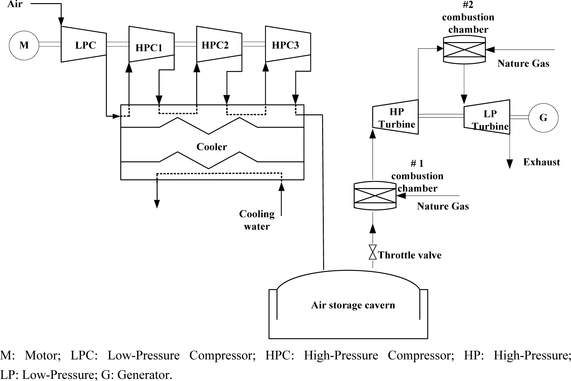
2.1. Introduction of the Traditional CAES

In the traditional CAES (Huntorf), NG is used as the fuel, and two-stage combustion and expansion are adopted. Figure 1 illustrates the schematic of the traditional CAES. In the energy storage subsystem, air is compressed and cooled before it is injected into the air storage cavern. In the power generation subsystem, high-pressure air is released from the air storage cavern during peak hours. The released air is sequentially throttled to steady pressure, mixed with a certain amount of NG and then burned in the combustion chamber. The high-temperature and high-pressure fuel gas drives the turbine to rotate to activate the generator, which, in turn, generates electricity.

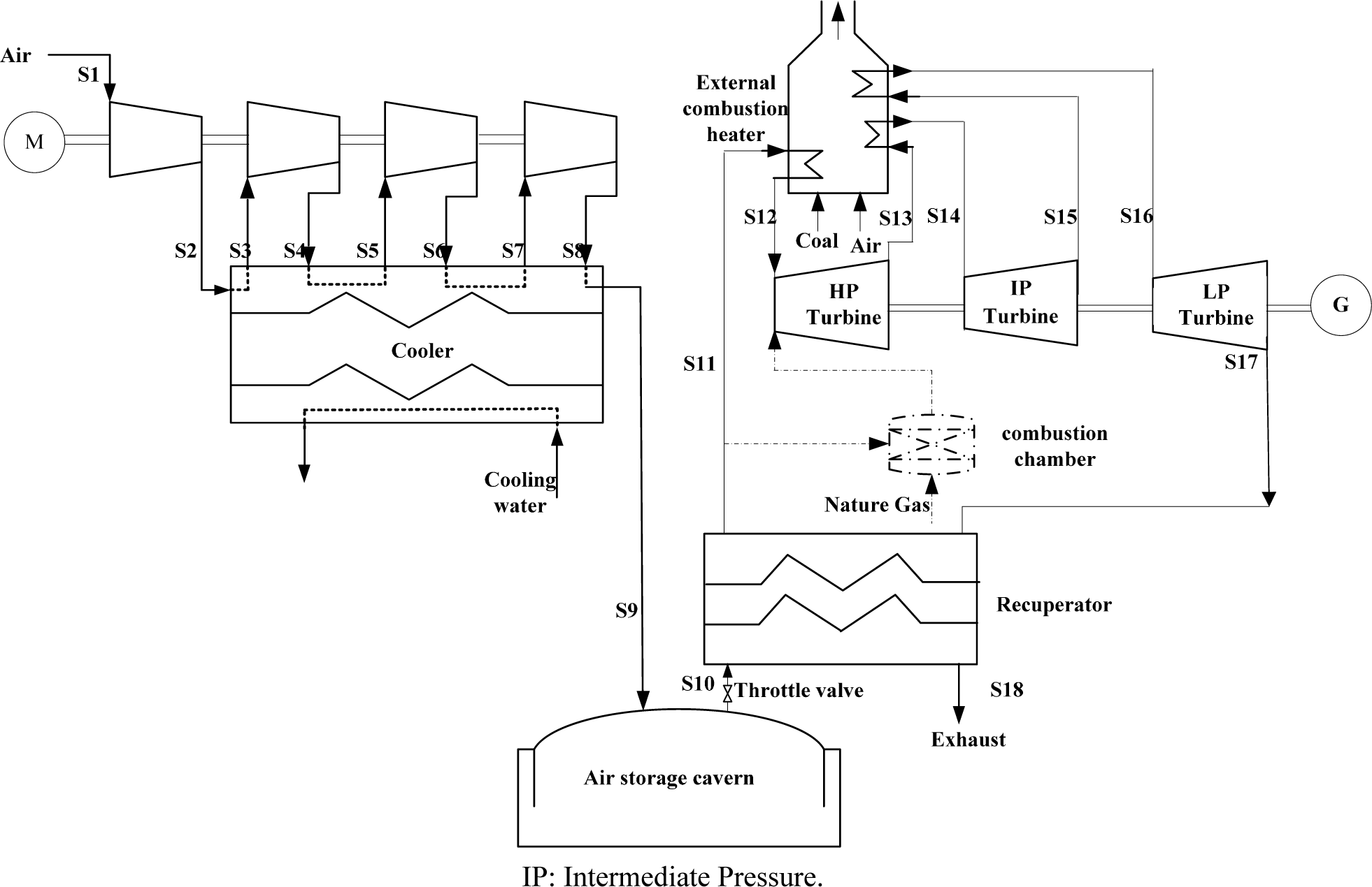
2.2. Proposed Coal-Fired CAES

The flow process diagram of the coal-fired plant is shown in Figure 2. In contrast to a traditional CAES, the combustion chamber is replaced by the external combustion heater with coal as fuel, and the turbine operates in a three-stage expansion. The high-pressure air is preheated in the recuperator after being throttled to a certain pressure. High-temperature flue gas is utilized to heat the air to a specified temperature in the external combustion heater. The heated air drives the high-pressure air turbine to work. Air exhaust from the high-pressure air turbine is then reheated in the external combustion heater to force the intermediate-pressure turbine to rotate. This process is the same as that in the low-pressure turbine. The air exhaust of the low-pressure turbine flows through the recuperator to exchange part of the residual heat with the outlet air of the air storage cavern. The three turbines are connected with a generator, which produces electricity.
Generally, compared with combined cycles with heat recovery steam generator (HRSG) and a steam turbine, the air-air recuperator is too large to be adopted by a common power generation system. However, there might be an exception when it comes to CAES; for example, for the CAES discussed in this paper, the exhaust air of the system (may be around 300 °C) needs to be cooled down to 100 °C, and it is difficult to realize the steam cycle with high efficiency at this relatively low temperature level. Besides, a relatively quick time response is required, since CAES is used for peak load regulation; in this case, a recuperator has the advantage over the steam-water system. Actually, the existing CAES power plant located in the USA, namely the McIntosh plant, also adopted a recuperator to recycle the waste heat.
The external combustion heater in the coal-fired plant is improved based on the heat pipe hot blast stove. The heat generated by coal in the heat pipe hot blast stove is supplied to the heat pipe heat exchanger in which heat transformation is conducted. The external combustion heater has three tube bundles set, and counterflow mode is adopted. The thermal efficiency of the heat pipe hot blast stove is 75% to 80% [16]. However, one drawback remains. The furnace temperature of a coal-fired boiler can generally reach up to 1300 °C, which could cause the heater to burn out given the low heat transfer coefficient of air; thus, a flue gas recirculation system is introduced. Exhaust gas mixes with high-temperature flue gas to reduce the temperature to approximately 800 °C and then exchanges heat with air, thereby ensuring heat pipe safety. Therefore, the highest temperature of heated air in a heat pipe hot blast stove can exceed 500 °C [17]. Thus, the heat pipe hot blast stove can be applied to the proposed CAES by employing optimization methods and acts as the heat transfer medium between the fuel gas and high-pressure air.
The introduction of an external combustion heater in the proposed system may depress the flexibility of the load following peak hours due to the large volume and relatively small heat transfer coefficient. One scheme is available to overcome this problem: adding a spare gas heater (internal combustion mode), as illustrated in the dotted line in Figure 2. The combustion chamber could provide a short-term power increasing solution during the start/quick power increasing process. Combined with the load regulation experiences of the existing CAES, basically a relatively stable partial load operation and start/stop can be expected.

2.3. Parameter Selection

For the purpose of convenient comparison, the size of the proposed CAES is selected by referring to the Huntorf CAES. The parameters of the proposed system, such as the flow rate of the working medium and the scale of the air storage cavern, are selected based on the Huntorf CAES; thus, the work output will be close to that of the Huntorf plant. Table 1 lists the basic assumptions of the coal-fired CAES and the Huntorf CAES. Air charging for 8 h in the energy storage subsystem can presumably meet 2 h of power generation in the power generation subsystem, i.e., the time ratio of air charging and discharging is 4:1 [8].
As for the power generation subsystem, an additional turbine is introduced into the coal-fired CAES, with three-stage expansion being adopted. After flowing through the throttling valve, air is depressurized to 64 bar at a constant temperature. The air is then heated to 580 °C by the external combustion heater after crossing the recuperator. The high-pressure turbine adopted is the air turbine type considering the high inlet air pressure. Although nowadays, the inlet temperature of gas turbines can reach as high as 1480–1600 °C [18,19], the initial temperatures of the intermediate and low-pressure turbines are set to 580 °C, because of the external combustion heater; this temperature is about 250 °C lower than the initial temperature of the low-pressure turbines in the Huntorf CAES. The adiabatic efficiency of the turbine can be improved by 90%, according to the literature [20]; thus, the adiabatic efficiencies of three turbines are assumed to be 88%, 90% and 90% respectively. The high-temperature exhaust is cooled to 100 °C after flowing through the recuperator.

3. Simulation of the Proposed Coal-Fired CAES

3.1. Evaluation Criterion

To evaluate the proposed CAES, this study adopts four common evaluation criteria [21], including the energy rate (ER), heat rate (HR), overall efficiency (ηee) and efficiency of electricity storage (ηes). ER can be expressed as:
E R = W c W t
where Wc refers to the power consumption of the compressors and Wt is the net output of electric energy. HR can be expressed as:
H R = Q f W t
where Qf indicates the total fuel input. The computational formula of ηee is:
η ee = W t Q f + W c = 1 E R + H R
The overall efficiency (ηee) comprehensively evaluates the energy storage efficiency of CAES, as it thoroughly considers the two subsystems that work during different periods. Therefore, ηee is considered the core criterion for evaluating the CAES. It is worthy to note that the input energy of the CAES from the two subsystems not only involves the chemical energy of fuel, but also includes the electric energy. Actually, it is an efficiency concept derived from the first law of thermodynamics, that is the ratio of the total energy output to the total energy input (including various kinds of energy, such as work, chemical energy of the fuel, etc.).
η es = W t Q f η sys + W c
The efficiency of electricity storage (ηes) equals the ratio of the output electric energy to the total equivalent input electric energy (i.e., input electric energy plus equivalent electric energy of the fuel input); it projects the storage efficiency of the energy storage/release process. The conversion coefficient or system efficiency, ηsys, implies the average conversion efficiency of converting a certain fuel to work. As far as a coal-fired power plant is concerned, the ηsys value is within the range of 34% to 42%, whereas the value is generally about 50%–60% for a gas turbine power plant [22]. For the proposed coal-fired CAES, ηsys is set to 38% and 55% for the Huntorf CAES.

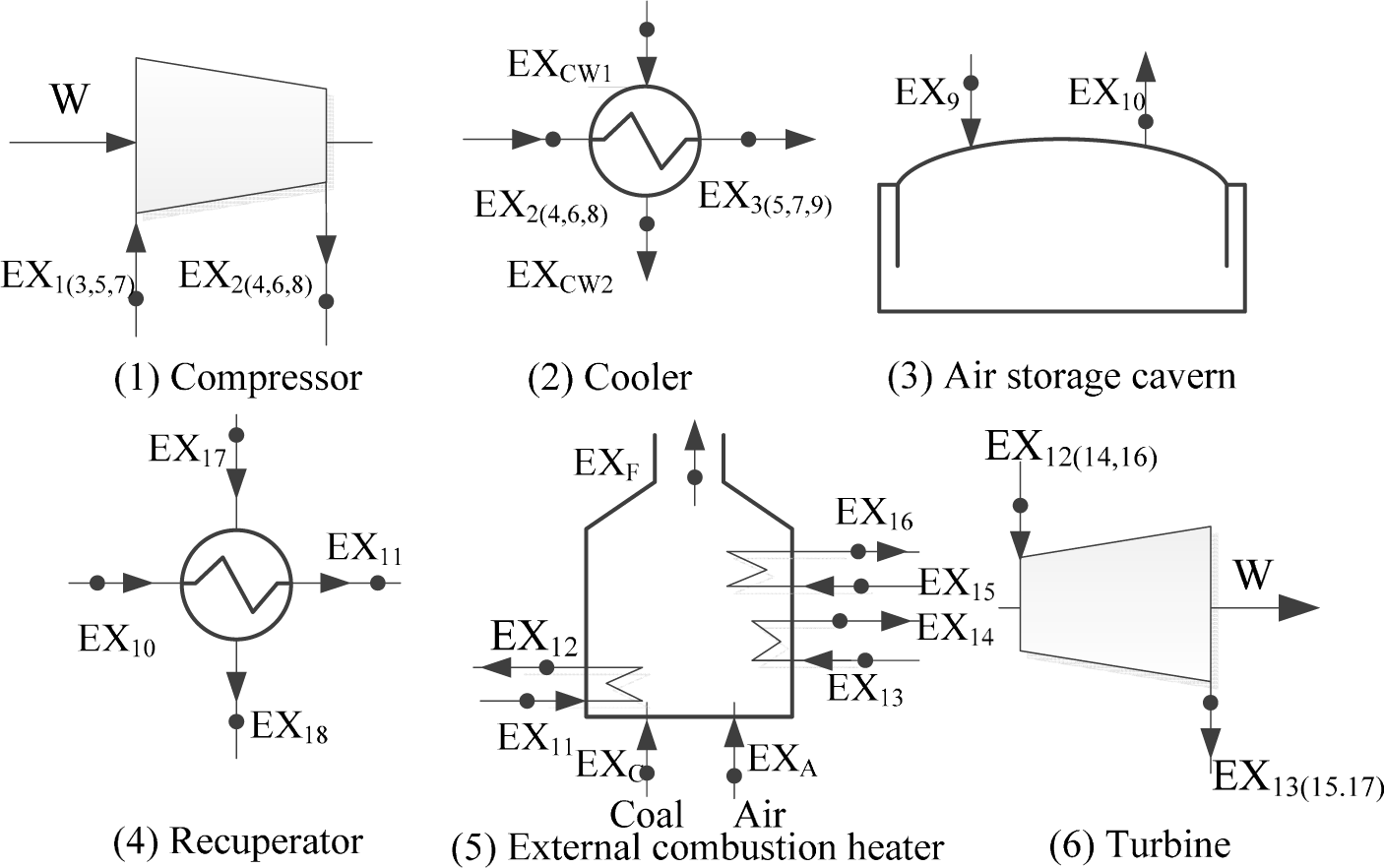
3.2. Process Simulation

The proposed CAES is simulated using the commercial software Aspen Plus 11.1. The input condition of each component is based on the design parameters, which are listed in Table 1. The Peng-Robinson (P-R) equation is adopted for all of the physical and chemical processes involved in the system. The compressor applies the “Compr” model; the external combustion heater and cooler apply the “Heater” model; the recuperator adopts the “MheatX” model; and the combustion chamber applies the “RStoic” model. During the simulation, the following assumptions are made: all thermodynamic processes are adiabatic; within the air compression process, air is cooled to 35 °C after flowing through each cooler; and the internal pressure of the storage cavern varies in actual operation, with the average pressure (82 bar) adopted, which is considered an acceptable operation pressure for the storage cavern. The average outlet temperature of the storage cavern is set to 50 °C; high temperature air exhausted from the low-pressure turbine is cooled to 100 °C after passing through the recuperator; the air flow rate keeps constant during the compression and expansion process; the completed combustion of the NG can be expected in the combustor. The external combustion heater adopted in this paper is developed based on the heat pipe hot blast stove; it consists of three groups of heat exchange tubes, and the heat exchange mode applies the countercurrent type. In addition, flue gas recirculation system is utilized to reduce the flue gas temperature and to ensure the safe operation of the heat exchange tubes. The Huntorf CAES is also simulated based on the parameters listed in Table 1. Table 2 presents the parameters of the main points that correspond to the coal-fired CAES, where T represents the temperature, P indicates the pressure and M is the mass flow rate. Details on the stream number are shown in Figure 2.

3.3. Thermodynamic Performance Analysis

The thermodynamic performance indicators of the proposed coal-fired CAES are calculated according to the simulation results above combined with the formulas provided in Section 3.1. For better comparison, analysis of Huntorf CAES with improved parameters is also conducted: assuming Huntorf CAES utilizes a recuperator and the compressors and turbines with the same efficiency as the proposed CAES, while other parameters are identical with Huntorf CAES. The simulation results of the coal-fired CAES, Huntorf CAES and improved Huntorf CAES are compared in Table 3.
The ER of the coal-fired CAES is slightly lower, and its HR is reduced significantly compared with the results of the Huntorf CAES, as shown in Table 3. The reduction in ER can be attributed to two aspects: one is the coal-fired CAES, adopting the three-stage expansion and increasing the inlet air pressure of the high-pressure turbine, which brings additional power output; and the other is the adopted compressor yielding a high adiabatic efficiency because of the increasing development of the compressor technology, thereby reducing ER. As for the reduction in the HR, the reasons are as follows: the outlet air temperature of the external combustion heater can only reach 580 °C, which indicates that the required heating capacity is relatively small. Moreover, the recuperator not only reduces the exhaust heat loss considerably, but also increases the outlet air temperature of the gas storage cavern, which means a smaller amount of heat is required to heat the air to the same temperature. As a result, the HR of the proposed coal-fired CAES is reduced.
In the improved Huntorf CAES, the improvement of the compressor and turbine efficiency leads to the distinct reduction in ER. Besides, due to the adoption of the recuperator, its HR is also significantly reduced to 1.09, even lower than that of coal-fired CAES. The reason lies in that, in the external combustion heater of coal-fired CAES system, coal is used as the fuel, and the heat exchange process is carried out between the air and flue gas, resulting in relatively low combustion efficiency and heat exchange efficiency. While in the combustion chamber of the improved Huntorf CAES, NG and air are mixed and combusted directly, thereby higher combustion efficiency and lower heat loss could be achieved.
The overall efficiency of the coal-fired CAES reaches 48.37%, which is much higher compared with the Huntorf CAES, but lower than that of the improved Huntorf CAES. The efficiency of the electric energy of the coal-fired CAES can reach 81.50%, 21.50% higher than that of the Huntorf CAES and still 4.26% higher than that of the improved Huntorf CAES. This result indicates that: the thermodynamic perfection level of the coal-fired CAES is almost the same as the improved Huntorf CAES when excluding the utilization efficiency difference between NG and coal. In other words, the proposed coal-fired CAES realizes the efficient utilization of the energy resources.
Notably, the coal-fired CAES is proposed based on the national condition of China, which is abundant in coal, but short of NG. It is suitable for the peak load regulation of renewable electricity generation (wind farm, for example), as well as for coal-rich areas (while short of NG).

4. Discussion

4.1. Exergy Analysis

In the previous section, thermodynamic performance analysis is conducted based on the first law of thermodynamics, which mainly focuses on energy quantity. However, energy is characterized not only by its quantity, but also by its quality, which means different energies possess different energy grades. Hence, from the perspective of the second law of thermodynamics combined with the first law of thermodynamics, the internal energy transformation of the system is further analyzed in this section. The exergy balance analysis method is also widely applied to various thermodynamic system research [2325].
Figure 3 depicts the exergy flow in the main components of the system. In this study, exergy analysis is conducted through three aspects, including exergy input, exergy output and exergy destruction.
Exergy input is composed of the exergy input of air (EXa), the power consumption of the compressors (Wc) and the fuel input of the external combustion heater (EXc). Exergy output is determined by the power output of the system (Wt). Among them, Wc, Wt, and the fuel input of the external combustion heater can be obtained via Aspen simulation. EXc can be calculated according to Formula (5): the ratio of EXc to HL for coal is 1.035, and for NG, this value is assumed to be 1.04 [26,27]. EXa can be calculated by using Formula (6):
E X c = H L ( 1.0064 + 0.1519 [ H ] [ C ] + 0.0616 [ O ] [ C ] + 0.0429 [ N ] [ C ] )
E X a = ( H a H 0 ) T 0 ( S a S 0 )
where HL is the low heating value of the fuel, [H], [C], [O] and [N] are the mass fractions of H, C, O and N, respectively. Subscript 0 indicates that the properties are taken at environmental temperature conditions (T0 = 25 °C, P0 = 101 kPa), and Ha and Sa denote the inlet air enthalpy and entropy of the compressor, respectively.
The general exergy balance of the system components can be expressed as:
Σ E X in = Σ E X out + I r + E X loss
where EX(in) and EX(out) refer to the exergy input and exergy output, respectively, which take working mediums, electricity and heat into consideration. Ir indicates the exergy destruction, and EXloss represents the exergy loss caused by energy loss. However, heat dissipation is negligible during the energy conversion process, so that all thermodynamic processes of the simulation models are assumed adiabatic. Therefore, the energy loss can be ignored and is considered zero. The general exergy balance of the system components can thus be expressed in the following rate form:
Σ E X in = Σ E X out + I r
Exergy destruction is unavoidable in the actual thermodynamic process. Exergy destruction is caused by the circulation of working mediums and energy transformation, as well as the abandonment of exhaust working mediums. In the proposed system, the exergies of the exhaust streams and the cooling compression heat are wasted and, thus, are categorized as exergy destruction. According to the general exergy balance Formula (8), specific exergy balance formulas of the main components, including compressors, coolers, air storage cavern, recuperator, external combustion heater and turbines, are listed in the formulas (9)(14) below, respectively. Each item in the six formulas corresponds to the exergy flow of the corresponding components in Figure 3. The exergy of the exhaust stream (EXe) can be obtained by changing the subscript “a” into “e” in Formula (6).
I r , Com = W + E X 1 E X 2 + E X 3 E X + 4 E X 5 E X + 6 E X 7 E X 8
I r , Coo = E X 2 E X 3 + E X 4 E X + 5 E X 6 E X + 7 E X 8 E X 9
I r , ASC = E X 9 E X 10
I r , Rec = E X 10 + E X 17 E X 11 E X 18
I r , ECH = E X C + E X A E X F + E X 11 E X 12 + E X 13 E X 14 + E X 15 E X 16
I r , Tur = E X 12 E X 13 + E X 14 E X 15 + E X 16 E X 17 W
For the external combustion heater, air output exergy is extremely little, such that it can be omitted when compared with the coal output exergy; thus, EX2 in Formula (13) can be removed.
The abovementioned steps elaborate the exergy analysis method of the coal-fired CAES. The exergy analysis of the Huntorf CAES can be performed similarly. The exergy analysis of the coal-fired CAES and the Huntorf CAES are compared in Table 4 (including the improved Huntorf). The exergy efficiency of proposed system is approximately 7% higher than that of the Huntorf CAES.
The exergy of exhaust stream of the coal-fired CAES is much lower than that of the Huntorf CAES. Table 4 shows that the exergy of the exhaust stream in Huntorf CAES takes 10.49% of the total exergy input because the exhaust stream temperature reaches as high as 423.8 °C. This part of heat exergy is wasted, as it is discharged into the atmosphere directly. However, a recuperator is adopted in the coal-fired CAES to recycle the residue heat of the exhaust stream. Therefore, the proportion of the exergy of the exhaust stream in the total exergy destruction is reduced to 0.69%. Despite this result, the additional recuperator brings extra exergy destruction, which can be omitted because it occupies only 1.16% of the total exergy destruction. Therefore, adopting a recuperator in the proposed coal-fired CAES efficiently utilizes the exergy of exhaust streams, thereby enhancing energy utilization efficiency. Recycled heat is also used to preheat the air released from the air storage cavern, thereby reducing the heat required by the combustion process. The thermodynamic performance of the proposed coal-fired CAES is improved remarkably.
The exergy destructions of the combustion process in both systems are relatively high. Within the external combustion heater, indirect heat exchange between the cold air and flue gases proceeds to the heat exchange tubes, whereas air and NG are mixed and combusted directly in the combustion chamber. Therefore, if the working medium is heated to the same temperature, the exergy destruction of the external combustion heater is higher than that of the combustion chamber. Nevertheless, the outlet air temperature of the external combustion heater can reach only 580 °C, lower than that of the combustion chamber (825 °C). As a result, the difference in the exergy destruction between the external combustion heater and combustion chamber is relatively small, and results show that the exergy destruction of the former is about 5% higher than the latter.
If the exhausted air passes through a recuperator in the improved Huntorf CAES, the exergy loss of the exhausted air can also be significantly reduced to 1.80%, and the exergy destruction of the recuperator is only 1.51%. The exergy destruction of combustion chamber is reduced because the introduction of the recuperator can effectively reduce the heat amount required by the working medium, given the same target parameter. Consequently the exergy efficiency can be improved to 54.41%, 7% higher compared to the proposed CAES.
However, the coal-fired CAES is proposed in view of the specific energy mix of China, which is abundant in coal, but short of NG. Particularly, for the “Three Norths” area in China, the double effects of geographical isolation and the higher price of natural gas make it difficult to achieve large-scale NG supply. Therefore the development of conventional CAES had been stalled for years, while the proposed CAES may provide a feasible solution to promote the development of CAES in China. In conclusion, the proposed CAES has great developing potential in China in spite of its relatively low exergy efficiency.
The proposed system can be further improved. The key factor that limits the improvement of its exergy efficiency is the low initial temperature of turbines, which reduces the exergy input of working mediums, thereby decreasing the working capacity. Therefore, the proposed system can perform better if the outlet air temperature of the external combustion heater is increased. In addition, the cooling compression heat exergy occupies over 6% of the total exergy input; this part of exergy is partly transmitted to the cooling water, which becomes low-grade steam with low parameters afterwards. Usually, the steam is abandoned in the two systems, which results in exergy destruction. However, low-grade heat can be efficiently utilized in the modern refrigeration industry. Therefore, if this wasted heat can be applied to the refrigeration cycle, the energy utilization rate can be improved accordingly.
One interesting thing can be found, as the exergy efficiency of three processes is close to the overall efficiency. The main reason lies in that the exergy of input/output work equals the work itself, and the difference only exists in Ef and Qf. According to Formula (5), the ratio of EXc to HL (1.035 for coal and 1.04 for NG) is rather small and has little effect on the results. As a result, the exergy efficiency is close to the electrical efficiency numerically.

4.2. Techno-Economic Analysis

4.2.1. Investment Cost Estimation of CAES Plant

The cost of a CAES plant is mainly composed of the total construction cost (TCC), operation and maintenance cost (O&M), fuel cost, electricity cost, etc. The investment cost of the CAES and McIntosh power plants is approximately $560/kW. As noted in the Introduction, the investment cost of a CAES plant is between $400/kW and $1370/kW at present [1,57]. Constructing an air storage cavern (the underground equipment) is highly demanding with respect to geographical condition. Assuming the largest rated air storage scale of a coal-fired CAES is 12 h, the construction cost of the air storage cavern is expected to be $100/kW [28,29]. Table 5 provides an overview of the main components in CAES for our analysis, which were compiled from different sources [30,31]. The O&M cost is generally about 0.6% to 2% of a total plant investment, and it is assumed to be 2% here [5]. If CAES plants are developed in the “Three Norths” area in China, with the peak and valley time prices varying in different areas, the off-peak electricity price is within the range of $40/MWh to $71/MWh [32,33]. According to the domestic average steam coal price in 2014, the standard coal price is calculated as $77/t to $100/t [34]. Assuming the base-load time of the coal-fired CAES plant is 1200 h annually, the discounted rate (k) and the life span of the main equipment (l) are set to 10% and 25 years, respectively [35,36]. The investment cost of a coal-fired CAES, with its specific economic conditions comprehensively considered, is presented in Table 6.
To evaluate the economic feasibility of the coal-fired CAES plant, the cost of electricity (COE) is selected as the evaluation indicator in this study. COE is defined as follows:
C O E = A O & M C + A C C + A O E C + ( C R F ) ( T C C ) A E O
where AO&MC represents the annual O&M cost, ACC denotes the annual coal cost, AOEC is the annual off-peak electricity cost, TCC indicates the total construction cost, AEO denotes the annual electricity output and CRF is the capital recovery factor, which can be calculated using Formula (16).
C RF = [ k ( 1 + k ) l ] / [ ( 1 + k ) l 1 ]
According to the data listed above and Formula (15), the COE of the coal-fired CAES plant is calculated, as shown in Table 7.
Under the selected economic condition, the COE of the coal-fired CAES plant is relatively high, reaching $106.33/MWh. The advantages of CAES plants are presumably weakened by the increasingly fierce competition expected in the power market.
To further investigate the techno-economic performance of the coal-fired CAES, a comparison between the coal-fired CAES and the conventional NG-fuel CAES is carried out. The conventional NG-fuel CAES adopts two combustion chambers instead of an external combustion heater to heat high-temperature gas for turbines, and only natural gas is used as the fuel in its combustion chambers. Other parts of the two CAES plants are identical with respect to the structure and parameters. Consequently, the COE of conventional CAES reaches 143.42 $/MWh, which is higher compared to the coal-fired CAES. The reason lies in that the cost of NG in China can be as high as 10–12 $/GJ, which is nearly 4–5 times the price of coal (2–4 $/GJ).

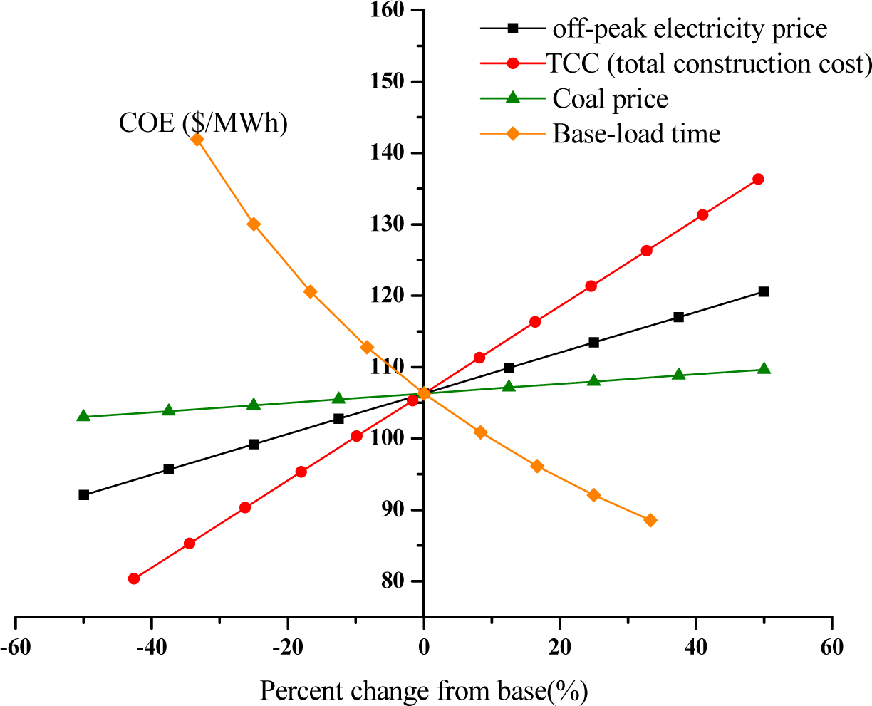
4.2.2. Sensitivity Analysis

The generation cost of a CAES plant will be affected by the power market, government policies and specific factors, including off-peak electricity and coal prices. Moreover, TCC and the annual base-load time significantly affect the economic performance of CAES plants. Thus, sensitivity analysis is performed to reveal the changing patterns of COE when these four factors vary.
Figure 4 shows that the COE of the coal-fired CAES indicates linear positive growth with the increments of off-peak electricity price, coal price and TCC. By contrast, a nonlinear negative growth in COE is observed when the base-load time increases. A comparison among the four curves indicates that the most subtle change is observed in the curve that represents the coal price; the COE of the coal-fired CAES plant gradually climbs from $103.00/MWh to $109.66/MWh when the coal price increases from $40/t to $130/t, which shows that coal price has a relatively limited effect on the COE compared with other factors. To a certain extent, off-peak electricity price will also affect the COE, as COE of the coal-fired CAES plant is reduced to $92.086/MWh at the off-peak electricity price of $20/MWh. Both the base-load time curve and TCC curve display a steep changing pattern. When the base-load time varies from 800 h to 1600 h, annual off-peak electricity cost (AOEC) doubles from $7.23/MWh, along with a doubled annual electricity output. Consequently, COE rapidly reduces from $141.91/MWh to $88.534/MWh. If TCC declines to $400/MWh, the corresponding COE is only $85.325/MWh.
The COE of the coal-fired CAES plant can be reduced effectively by properly cutting down the off-peak electricity price, reducing the construction cost and increasing the base-load time.
  • For most of the “Three Norths” area in China, the off-peak electricity price can be reduced to $40/MWh at most, which means more effort should be devoted to regulating the grid purchase price to further reduce the COE. The on-peak electricity price in most areas in China is about $96/MWh to $130/MWh [32], exceptionally; however, this price can reach up to $193/MWh in some areas (e.g., Beijing) [33]. Hence, more power generated by the CAES plant should be delivered to these areas. Corresponding policies should be implemented for the energy storage plants. For example, more government subsidies should be provided to regulate the grid purchase price of energy storage plants. The power grid should be more mature.
  • In this study, the construction cost of the coal-fired CAES plant is estimated by referring to the existing CAES plants. The investment cost of the air storage cavern is about 16% of the total construction cost. Such a cost can be reduced significantly if suitable air storage caverns are discovered. The cost of the low-temperature turbine is also relatively low because of the low requirement for high temperature resistance. These two factors are beneficial to reduce the TCC of the coal-fired CAES plant.
  • Power grids are becoming more complicated to regulate when renewable power is in parallel with the power grid. Therefore, more peak load shaving units will be needed, and CAES can make a contribution. In this way, more power can be stored to then generate more electricity annually by the CAES plant to provide more effective power peak load shaving. Therefore, the base-load time is increased, thereby significantly reducing the COE of the CAES plant.
The proposed coal-fired CAES is economically feasible given a positive economic condition or major technical breakthroughs.
As for the environmental implications of the replacement of NG by coal, the coal-fired CAES is inferior to the conventional one with respect to CO2 emissions. For comparison, the molar masses of carbon and CO2 are 12 g/mol and 44 g/mol, and the average carbon content of Chinese coal is 0.0258 g carbon/kJ [37]. Calculation shows that the CO2 emissions of the coal-fired CAES amounts to approximately 460 gCO2/kWh, while for the conventional NG-fuel CAES, this value is 217 gCO2/kWh. However, from the regional energy system level, CAES is beneficial to improve grid regulation strength, to reduce wind curtailment and to increase the portion of renewable power generation, which will bring considerable emission reduction benefits. In this case, the coal-fired CAES may be useful for CO2 emissions reduction as a whole.

5. Conclusion

In the proposed coal-fired CAES, the external combustion heater upgraded based on the heat pipe hot blast stove is introduced to replace the combustion chamber. The proposed CAES uses coal as the fuel, as China is rich in coal. This makes the system more suitable for the energy structure of China than the traditional one. With the development of technologies, the performance of the compressor and turbine is improved, as reflected in the high adiabatic efficiencies of these two devices. Three-stage turbines are adopted in the power generation subsystem. The system performance analysis of the coal-fired CAES is conducted in theory, and exergy and techno-economic analyses are performed.
  • The improvement of the equipment performance and system configuration makes the system perform well. The recuperator reduces the exhaust heat loss considerably and increases the outlet air temperature of the gas storage cavern. However, the combustion efficiency and heat exchange efficiency of the external heater are lower than those of the combustion chamber. As a result, the overall efficiency of the coal-fired CAES reaches 48.37%, higher than that of the Huntorf CAES, but lower than the improved Huntorf CAES, noting that the efficiency of the electricity of the proposed CAES is the highest.
  • The exergy efficiency of the proposed coal-fired CAES is 47.22%, approximately 7% higher than that of Huntorf. This improvement is mainly attributed to the decrement of the exergy of the exhaust stream; the largest exergy destruction observed in the external combustion heater. Therefore, the exergy efficiency can be further improved through measures, such as optimizing the external combustion heater. Additionally, the cooling compression heat exergy is wasted in vain, so utilizing the cooling compression heat properly can also increase the exergy efficiency.
  • In terms of techno-economic performance, the COE of the coal-fired CAES is $106.33/MWh, which is 26% lower compared to the conventional NG-fuel CAES with a similar capacity. The reason is that the price of NG is far higher compared to that of coal. Sensitivity analysis is conducted by varying factors, such as off-peak electricity price, coal price, total construction cost and annual base-load time. The proposed CAES will be more competitive if the following conditions are addressed: (i) the power grid should be improved to encourage energy storage plants with the least delay possible; (ii) the cost of a low-temperature turbine is lower; the total construction cost can also be reduced provided that a suitable cavern is found; (iii) more power can be stored to enable the CAES plant to generate more power for power peak load shaving.
The coal-fired CAES proposed in this study is technically reliable and economically feasible under relatively positive economic conditions. This proposed system is particularly suitable for China’s national energy condition given that China is rich in coal, but short of NG, and has great developing potential in China. Therefore, the recommendation is for China to be supportive of the development of the proposed CAES technology, because it suits domestic conditions.

Acknowledgments

The paper is supported by the National Nature Science Fund of China (No.51276059).

Author Contributions

In this paper, Wenyi Liu provided the original idea and constructed its framework, and was responsible for drafting and revising the whole paper; Qing Li conducted the detailed calculation, simulation and contributed to revising the paper. Feifei Liang contributed to improving the English writing of the whole paper. Linzhi Liu devoted efforts to some valuable comments on revising the paper. Gang Xu devoted efforts to revising the paper. Yongping Yang was the main technical guidance. All authors have read and approved the final manuscript.

Conflicts of Interest

The authors declare no conflict of interest.

References

  1. Chen, H.S.; Cong, T.N.; Yang, W.; Tan, C.Q.; Li, Y.L.; Ding, Y.L. Progress in electrical energy storage system: A critical review. Prog. Nat. Sci. 2009, 19, 292–294. [Google Scholar]
  2. Fernandes, D.; Pitie, F.; Caceres, G.; Baeyens, J. Thermal energy storage: “How previous findings determine current research priorities”. Energy 2012, 39, 246–257. [Google Scholar]
  3. Gil, A.; Medrano, M.; Martorell, I.; Lazaro, A.; Dolado, P.; Zalba, B.; Cabeza, L.F. State of the art on high temperature thermal energy storage for power generation. Part 1—Concepts, materials and modellization. Renew. Sustain. Energy Rev 2010, 14, 31–55. [Google Scholar]
  4. Delille, G.; Francois, B. A review of some technical and economic features of energy storage technologies for distribution system integration. Ecol. Eng. Environ. Prot. 2008, 1, 40–49. [Google Scholar]
  5. Zach, K.; Auer, H.; Lettner, G. Report summarizing the current Status, Role and Costs of Energy Storage Technologies; StoRE Project: Vienna, Austria, 2011. [Google Scholar]
  6. Cavallo, A.J. Energy storage technologies for utility scale intermittent renewable energy systems. J. Sol. Energy Eng 2001, 123, 387–388. [Google Scholar]
  7. Fertig, E.; Apt, J. Economics of compressed air energy storage to integrate wind power: A case study in ERCOT. Energy Policy 2011, 39, 2337–2338. [Google Scholar]
  8. Crotogino, F.; Mohmeyer, K.U.; Scharf, R; Huntorf, CAES. More than 20 years of successful operation, In Proceedings of Solution Mining Research Institute Meeting, Orlando, FL, USA, 15–18 April 2001.
  9. Zafirakis, D.; Kaldellis, J.K. Autonomous dual-mode CAES systems for maximum wind energy contribution in remote island networks. Energy Convers. Manag. 2010, 51, 2150–2161. [Google Scholar]
  10. Zhao, P.; Dai, Y.; Wang, J. Design and thermodynamic analysis of a hybrid energy storage system based on A-CAES (adiabatic compressed air energy storage) and FESS (flywheel energy storage system) for wind power application. Energy 2014, 70, 674–684. [Google Scholar]
  11. Kim, Y.-T.; Lee, Y.-H. A hybrid energy storage system using pump compressed air and micro-hydro turbine. Renew. Energy. 2014, 65, 117–122. [Google Scholar]
  12. Zunft, S.; Jakiel, C.; Koller, M.; Bullough, C. Adiabatic compressed air energy storage for the grid integration of wind power, In Proceedings of the 6th International Workshop on Large-Scale Integration of Wind Power and Transmission Networks for Offshore Windfarms, Delft, The Netherlands, 26–28 October 2006.
  13. Grazzini, G.; Milazzo, A. Exergy analysis of a CAES with thermal energy storage, In Proceedings of the 5th European Thermal Sciences Conference, Eindhoven, The Netherlands, 18–22 May 2008.
  14. Zhang, Y.; Yang, K.; Li, X.; Xu, J. The thermodynamic effect of thermal energy storage on compressed air energy storage system. Renew. Energy. 2013, 50, 227–235. [Google Scholar]
  15. National Bureau of Statistics of China. Available online: http://www.stats.gov.cn/tjsj/ndsj/2013/indexch.htm accessed on 31 December 2013. In Chinese.
  16. Pan, P.; Wang, X. Modern Drying Technology; Liu, X., Ed.; Chemical Industry Press: Beijing, China, 2006; pp. 1395–1399, In Chinese. [Google Scholar]
  17. Wang, Y. Configuration Analyses and Optimization Design of Hot-Blast Stove. Master’s Thesis, Harbin Institute of Technology, Harbin, China, 2006; pp. 12–15. [Google Scholar]
  18. Yuri, M.; Masada, I.; Tsukagoshi, K.; Ito, E.; Hada, S. Development of 1600°C-class high-efficiency gas turbine for power generation applying J-Type technology. Mitsubishi Heavy Ind. Tech. Rev. 2013, 50, 2–10. [Google Scholar]
  19. Gas Turbine World, Gas Turbine Word 2013 GTW Handbook; Volume 30, Pequot Publishing Inc: Fairfield, CT, USA, 2013; pp. 20–35.
  20. Shi, X.J.; Agnew, B.; Che, D.F.; Cao, J.M. Performance enhancement of conventional combined cycle power plant by inlet air cooling, inter-cooling and LNG cold energy utilization. Appl. Therm. Eng. 2010, 30, 2005–2006. [Google Scholar]
  21. Taylor, J.; Halnes, A. Analysis of compressed air energy storage, In Proceedings of PCIC Europe 2010 Conference Record, Oslo, Norway, 15–17 June 2010; pp. 1–5.
  22. Mao, J.X. The Road of High Efficiency Coal Power in China. accessed on 16 July 2014. Available online: http://www.esc.ethz.ch/events/seminars/Mao.pdf.
  23. Kim, Y.M.; Favrat, D. Energy and exergy analysis of a micro-compressed air energy storage and air cycle heating and cooling system. Energy 2010, 35, 213–220. [Google Scholar]
  24. Liu, W.; Liu, L.; Zhou, L.; Huang, J.; Zhang, Y.; Xu, G.; Yang, Y. Analysis and optimization of a compressed air energy storage-combined cycle system. Entropy 2014, 16, 3103–3120. [Google Scholar]
  25. Kim, Y.-M.; Lee, J.-H.; Kim, S.-J.; Favrat, D. Potential and evolution of compressed air energy storage: Energy and exergy analyses. Entropy 2012, 14, 1501–1521. [Google Scholar]
  26. Song, Z. Energy Conservation Principle; Water Power Press: Beijing, China, 1985; pp. 212–292, In Chinese. [Google Scholar]
  27. Szargu, J.; Stryrylska, T. Approximate determination of the exergy of fuels. Brennstoff-Warme-Kraft 1964, 16, 589–596. [Google Scholar]
  28. Desai, N.; Gonzalez, S.; Pemberton, D.J.; Rathjen, T.W. The Economic Impact of CAES on Wind in TX, OK, and NM; Ridge Energy Storage & Grid Services LP; Texas State Energy Conservation Office: Austin, TX, USA, 2005. [Google Scholar]
  29. Denholm, P.; Sioshansi, R. The value of compressed air energy storage with wind in transmission-constrained electric power systems. Energy Policy 2009, 37, 3149–3158. [Google Scholar]
  30. Drury, E.; Denholm, P.; Sioshansi, R. The value of compressed air energy storage in energy and reserve markets. Energy 2011, 36, 4959–4967. [Google Scholar]
  31. Schainker, R.B.; Abhi, R. Compressed Air Energy Storage Scoping Study for California; Report Number CEC-500-2008-069; Electric Power Research Institute: Palo Alto, CA, USA, November 2008; pp. 21–37. [Google Scholar]
  32. The peak and valley time price will carried out in Gansu province. Bjx Smartgrid Homepage. Available online: http://www.chinasmartgrid.com.cn/news/20140313/496662.shtml accessed on 13 March 2014.
  33. Bejing Municipal Commission of development and reform. Available online: http://www.bj.sgcc.com.cn/html/files/2014-01/23/20140123183233629433184.pdf accessed on 20 January 2014.
  34. The average price of steam coal in China. Available online: http://www.sxcoal.com/dlm/index.html accessed on 16 July 2014.
  35. Madlener, R.; Latz, J. Economics of centralized and decentralized compressed air energy storage for enhanced grid integration of wind power. Appl. Energy. 2013, 101, 299–309. [Google Scholar]
  36. Xu, G.; Wu, Y.; Yang, Y.; Zhang, K.; Song, X. A novel integrated system with power generation, CO2 capture, and heat supply. Appl. Therm. Eng. 2013, 61, 110–120. [Google Scholar]
  37. Intergovernmental Panel on Climate Change, 2006 IPCC Guidelines for National Greenhouse Gas Inventories; Institute for Global Environmental Strategies: Kanagawa, Japan, 2006.
Figure 1. Schematic of the traditional CAES.
Entropy 16 05935f1
Figure 2. Flow process of the coal-fired CAES.
Entropy 16 05935f2
Figure 3. Exergy flow in the main components of the system.
Entropy 16 05935f3
Figure 4. Sensitivity analysis of the COE of the coal-fired CAES.
Entropy 16 05935f4
Table 1. Basic assumptions of the coal-fired CAES.
ParameterUnitCoal-fired CAESHuntorf
Energy storage subsystemWorking hoursh88
Air mass flowkg/s108108
Pressure ratio of high-pressure compressor32.15
Pressure ratio of low-pressure compressor36
Adiabatic efficiency of high-pressure compressor%8680
Adiabatic efficiency of low-pressure compressor%8682
Inlet air pressure of gas storage cavernbar8246–72

Power generation subsystemWorking hoursh22
Air mass flowkg/s417417
Inlet pressure of high-pressure turbinebar6442
Inlet temperature of high-pressure turbine°C580550
Inlet pressure of intermediate pressure turbinebar25.6
Inlet temperature of intermediate pressure turbine°C580
Inlet pressure of low-pressure turbinebar5.1211
Inlet temperature of low-pressure turbine°C580825
Adiabatic efficiency of high-pressure turbine%8885
Adiabatic efficiency of intermediate pressure turbine%90
Adiabatic efficiency of low-pressure turbine%9085
LHV of coalMJ/kg29.3129.31
LHV of nature gasMJ/kg50.0350.03
Efficiency of external combustion heater%80
Table 2. Parameters of main points of the coal-fired CAES. P: pressure; M: mass flow rate.
streamsT (°C)P (bar)M (kg/s)streamsT (°C)P (bar)M (kg/s)
S110.001.01108.00S1050.0064.00417.00
S2130.703.04108.00S11254.4064.00417.00
S335.003.04108.00S12580.0064.00417.00
S4166.109.12108.00S13419.7025.60417.00
S535.009.12108.00S14580.0025.60417.00
S6166.4027.35108.00S15312.905.12417.00
S735.0027.35108.00S16580.005.12417.00
S8167.0082.05108.00S17312.901.02417.00
S935.0082.05108.00S18100.001.02417.00
Table 3. Simulation results comparison between the coal-fired CAES, Huntorf CAES and improved Huntorf CAES.
ParameterCoal-fired CAESHuntorfImproved Huntorf
Main parametersof systemPower consumption by compressors (MW)56.4557.9053.00
Generation of electricity power (MW)317.15295.55306.31
Coal input (MJ/s)429.85
NG input (MJ/s)476.79335.53

EvaluationindicatorsER0.710.780.69
HR1.361.611.09
ηee (%)48.3741.7355.94
ηes (%)81.5060.0477.24
Table 4. Comparison of exergy analysis of three CAESs.
Coal-fired CAES
Huntorf CAES
Improved Huntorf
Value
MWh
Proportion
%
Value
MWh
Proportion
%
Value
MWh
Proportion
%
Exergy input
Air1.980.151.980.141.980.18
Power consumption by compressors451.5933.62463.2231.71424.0237.66
Exergy input of coal889.8066.24
Exergy input of NG995.5468.15699.9962.17
Subtotal1343.37100.001460.75100.001126100

Exergy output
Generation of electricity power634.2947.22590.9740.46612.6154.41
Exergy destruction
Exergy of exhaust air9.220.69153.2910.4920.211.8

Sub-system of energy storage

Compressors44.683.3363.954.3845.174.01
Coolers83.276.2097.456.6777.836.91
Air storage room27.962.0835.782.4534.983.11
Subtotal155.9111.61197.1813.50157.9814.03

Sub-system of electricity generation
Turbines37.062.7654.963.7641.193.66
Recuperator15.531.1616.991.51
External combustion heater494.7936.83
Combustion chamber458.7231.40274.1324.35
Subtotal547.3940.75513.6835.17332.3229.51
Total exergy output1346.81100.261455.1299.611123.1399.75

Error of exergy input & output (%)−0.260.390.25
Exergy efficiency (%)47.2240.4654.41
Table 5. Investment cost of the main components in CAES.
ItemsInvestment Cost(million$)Description
Compressor11.67Power Consumption: 56 MW
Turbine47.55Total Installed: 317 MW
Cooler11.67Heat Transfer Area: 714,400 ft2
Recuperator3.31Heat Transfer Area: 220,770 ft2
Air storage carven31.7012 h of storage
Table 6. Investment cost of the coal-fired CAES plant. O&M: operation and maintenance.
ItemsUnitValue
Power generationMW317
ER0.71
HR1.36
Cost, aboveground equipmentmillion $161.67
Cost, cavern developmentmillion $31.70
Total construction costmillion $193.37
O&Mmillion $3.87
Off-peak electricity price$/MWh40.00
Coal price$/t80
Base-load timeh/year1200
Table 7. Cost of electricity (COE) of the coal-fired CAES plant.
ItemsUnitValue
AO&MCmillion $3.87
ACCmillion $2.53
AOECmillion $10.85
CFR0.12
TCCmillion $193.46
AEOMWh380,575.40
COE$/MWh106.33

