Article

Thermal Characteristic Analysis and Experimental Study of a Spindle-Bearing System

College of Mechanical Science and Engineering, Jilin University, Changchun 130022, China
*
Author to whom correspondence should be addressed.
Submission received: 25 March 2016 / Revised: 25 May 2016 / Accepted: 20 July 2016 / Published: 22 July 2016
(This article belongs to the Special Issue Entropy Application in Tribology)

Abstract

:
In this paper, a thermo-mechanical coupling analysis model of the spindle-bearing system based on Hertz’s contact theory and a point contact non-Newtonian thermal elastohydrodynamic lubrication (EHL) theory are developed. In this model, the effect of preload, centrifugal force, the gyroscopic moment, and the lubrication state of the spindle-bearing system are considered. According to the heat transfer theory, the mathematical model for the temperature field of the spindle system is developed and the effect of the spindle cooling system on the spindle temperature distribution is analyzed. The theoretical simulations and the experimental results indicate that the bearing preload has great effect on the frictional heat generation; the cooling fluid has great effect on the heat balance of the spindle system. If a steady-state heat balance between the friction heat generation and the cooling system cannot be reached, thermally-induced preload will lead to a further increase of the frictional heat generation and then cause the thermal failure of the spindle.

Graphical Abstract

1. Introduction

Thermal characteristics are key factors that have significant influence on the machining precision of CNC (Computer Number Control) machine tool, such as temperature rise and thermal deformation. In the research and development stage of a novel CNC machine tool, thermal characteristic analysis and experimental study of the spindle system under the main operation conditions can effectively improve the performance of machine tools. The high stiffness and high precision of the spindle system mainly depend on the stability of the pre-tightening state, dynamic state, and thermal properties of the spindle bearing. The friction heat generation of the spindle bearing can cause thermal expansion of the spindle components and parts. The inconsistency of the expansion of the spindle parts can cause changes in the contact stress on the spindle bearing, and thereby increase the friction heat generation of the spindle bearing. If the spindle bearing cannot reach a steady-state thermal balance, thermal failure will appear. In recent years, many scholars have studied the thermal characteristics of the spindle through finite element analysis (FEA) and real-time monitoring [1,2,3,4]. It is also widely recognized that entropy generation is friction and wear’s important quantitative measure. Significant entropic tribological research has been conducted in Russia since the 1970s, so there is a practical application of the thermodynamic entropic method in the study of friction and wear [5,6].
Min and Shuyun [7] made a precision analysis and calculation of thermal contact resistance of the bearing, improving the thermal transfer model. Takabi and Khonsari [8] developed a ball bearing mathematical model of the frictional heat generation, heat transfer, and transient temperature distribution; experiments were performed for different speeds and loads to validate the model. Furthermore, Khonsari and Bryant [9,10,11,12] studied friction and wear as products of irreversible entropy by an interfacial dissipative process. They formulated the entropy generation theorem relating any form of degradation to the irreversible dissipative processes germane to the degradation mechanism. Entropy generation as related to tribology and thermal effects has been studied [13,14,15]. For certain combinations of thermal variables, the total entropy generated is minimized, so the model can be optimized. Bossmanns and Tu [16] developed a heat transfer model among the spindle units based on the finite difference method. Holkup et al. [17] developed a thermo-mechanical coupling model with axisymmetric structure of the high-speed spindle by using the finite element method to predict the temperature distribution of the spindle, the changes of the bearing stiffness, and the contact load with time. However, the influence of the spindle cooling system on the heat balance of the spindle was not considered. Through theoretical analysis and experimental study, Mizuta et al. [18] developed an accurate heat transfer model of the spindle bearing. In their model, the authors considered the changes of the thermal resistance with the rotated speed and the axial force, but the model was only suitable for the selection of the type of spindle bearing at the research and development phase and has its limitations when applied to the analysis of the whole spindle system.
The above studies calculated frictional moment and heat generation through empirical formulas; without considering the effect of the lubricant on the frictional stress and heat transfer, there is large error between the calculated results and the actual frictional heat generation. Frictional heat generation can be accurately calculated by a detailed analysis of the frictional shear stress, contact deflection, and rotation speed of the rolling elements and raceway with considering EHL. Previous studies did not consider the cooling system, or analyzed a cooling system with only one heat-transfer coefficient [19]. In fact, the parameters of the cooling system have a great effect on the temperature distribution of the spindle-bearing system, so it is very useful to analyze the cooling system in detail.
In this paper, first, contact deflection and load distribution between ball and inner (outer) raceway are calculated and analyzed under the effect of external load, preload and inertial loads. Second, based on the analysis and calculations of lubricating oil film, the frictional heat generation of the ball and raceways are calculated; moreover, a heat transfer model of the spindle system is developed and the temperature distribution of the spindle system is calculated. Finally, after the experimental verification of the temperature distribution model, the influence of different parameters on the thermal characteristic of the spindle system is further analyzed, to verify whether the proposed calculation method can be widely applied to research and development of the precise spindle under different operating conditions.

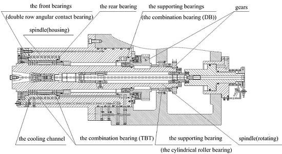
2. Thermo-Mechanical Coupling Model of the Spindle-Bearing System

This paper used the precise spindle of a new type of high-power horizontal machining center as the prototype to study the thermal characteristic of a spindle-bearing system, as shown in Figure 1. The spindle bearing (71928CD/P4ATBTA) (SKF, Goteborg, Sweden) is a triple angular contact ball bearings; the suffix TBT represents tandem duplex and back-to-back combination mode. The supporting bearing (71924CD/P4ADBA) (SKF, Goteborg, Sweden) is a back-to-back combination bearing; the suffix DB represents back-to-back combination mode. The bearing was preloaded using the axial sleeve, the adjustable collar, and the lock nut. The spindle cooling liquid was ISO VG32, whose temperature and flow were controlled by the oil cooler. The cooling jacket had a rectangular cross section. The spindle (rotating) and the cooling jacket were made of 15CrMo and 45 steel, respectively. The spindle system was equipped with a complete detection system used for real-time monitoring of the transient temperature field and the thermal displacement, and then for predicting the thermal failure.

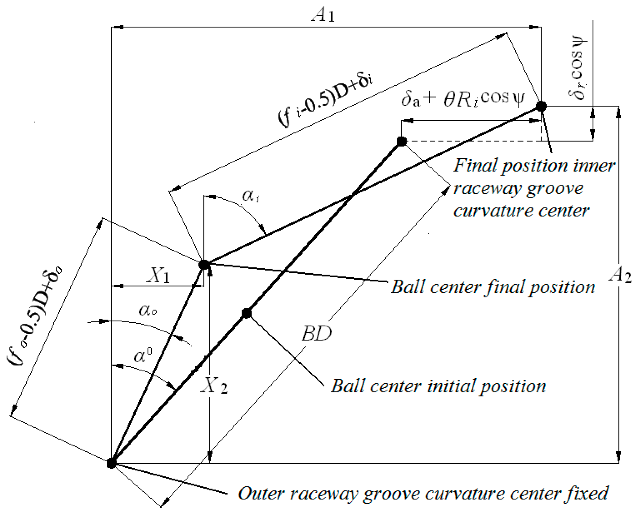
2.1. Deflection of High-Speed Ball Bearing under Applied Load

The main inner heat source that affects the spindle system is the spindle bearing friction heat generation, which can be calculated by numerical analysis. The main parameters that need to be considered are the internal load, the relative rotating speed, and contact deflection among the bearing elements. According to the Harris study [20], the contact deflection and internal load distribution of the ball bearing are analyzed and numerically calculated considering the external load, preload and inertial load.
Under spindle bearing operating conditions, centrifugal force acts on the rolling element. According to Figure 2, because the ball-inner and ball-outer contact angles are dissimilar, the line of action between the two centers will no longer be collinear with BD (Distance between raceway groove curvature centers) and becomes a broken line. It is assumed that the curvature center of the outer raceway groove in Figure 2 is fixed in space, and the curvature center of the inner raceway groove moves with the fixed center. In addition, because of the different contact angles of the inner and outer raceway grooves, the center of the rolling element will move accordingly.
At any ball position of the rolling element, the axial distance and the radial distance between the loci of the raceway groove curvature centers can be expressed, respectively, as follows [20]:
A 1 = B D sin α 0 + δ a + R i θ cos ψ A 2 = B D cos α 0 + δ r cos ψ   ,
where α0 is the initial contact angle when there is no load, δa and θ are the relative axial and angular displacement of the inner and outer rings, Ri is the radius of the locus of the inner raceway groove curvature center, δr is the relative radial displacement of the inner ring center, and ψ is the azimuth angle of the rolling element.
The new variables X1 and X2 are introduced to help the following analysis. Then the inner and outer contact angles for any position of the rolling element can be expressed as:
cos α o = X 2 ( f o 0.5 ) D + δ o ,         sin α o = X 1 ( f o 0.5 ) D + δ o cos α i = A 2 X 2 ( f o 0.5 ) D + δ i ,         sin α i = A 1 X 1 ( f o 0.5 ) D + δ i ,
where δi(o) is the normal contact deformation between the rolling element and the inner (outer) raceway groove, D is the diameter of the rolling element, and fo is the ratio of the curvature radius of the raceway groove to the diameter of the rolling element.
Use the Pythagorean Theory to obtain the following expressions from Figure 2:
( A 1 X 1 ) 2 + ( A 2 X 2 ) 2 [ ( f i 0.5 ) D + δ i ] 2 = 0 X 1 2 + X 2 2 [ ( f o 0.5 ) D + δ o ] 2 = 0   .

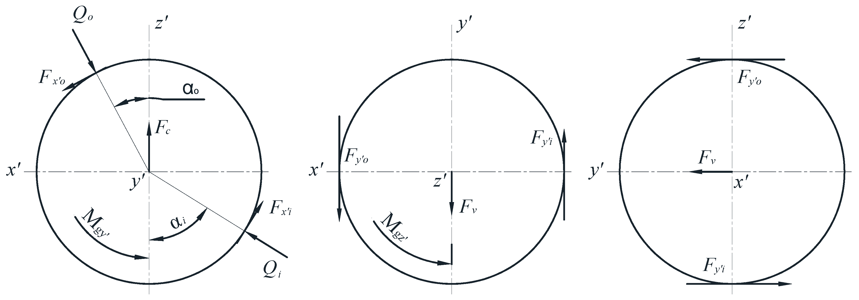
2.2. Frictional Heat Generation of High-Speed Ball Bearing

Harris provided a relatively complete dynamic analysis of rolling bearing; ball-raceway contact variables are solved by used the simplifying assumption of isothermal Newtonian lubricant. The comparison of the analytical results with the experimental data of Shevchenko, Bolan, Poplawski, and Mauriello shows that ball-raceway contact is calculated more accurate than the solution using the outer raceway control theory. A different approach on the basis of the theory of dynamical systems was suggested by Kagan [16], and it is based on the so-called Turing systems (the diffusion-reaction systems) to describe the spatial and time patterns induced by friction.
When the spindle bearing is operating under the lubrication condition, friction forces and friction moments between any rolling element and the raceway grooves are shown in Figure 3. The friction forces acting over the contact areas are Fx′n and Fy′n. In the x′z′ plane, friction force Fx′n, normal load Qn, and centrifugal force Fc achieve force equilibrium. In the x′y′ plane, friction force Fy′n, and viscous friction force Fv achieve force equilibrium. The moments due to the surface friction shear stresses are Mx′n, My′n, and Mz′n. Moments My′n and Mz′n achieve equilibrium at gyroscopic moments My′n and Mz′n, respectively.
The friction shear stress is described as given by Harries and Barnsby [20,21,22]:
τ = c v A c A 0 μ a σ + ( 1 A c A 0 ) [ ( η ( T , p ) v h ) 1 + τ lim 1 ] 1 .
Friction shear stress τ can be calculated using the formulas given in Appendix A [23].
Then the balance equations of the forces and moments for the rolling element of the spindle bearing can be expressed as [20]:
Q o cos α o Q i cos α i F x o sin α o + F x i sin α i F c = 0 Q o sin α o Q i sin α i + F x o cos α o F x i cos α i = 0 F y o F y i + F v = 0 Q o sin α o + F x o cos α o F a / Z = 0
D 2 1 1 1 q 2 1 q 2 [ a o b o τ y o cos ( α o + θ o ) + a i b i τ y i cos ( α i + θ i ) ] d t d q = 0 D 2 1 1 1 q 2 1 q 2 [ a o b o τ x o + a i b i τ x i ] d t d q M g y = 0 D 2 1 1 1 q 2 1 q 2 [ a o b o τ y o sin ( α o + θ o ) + a i b i τ y i sin ( α i + θ i ) ] d t d q M g z = 0 ,
where Qi(o) is the normal load between the rolling element and the inner (outer) raceway groove; Fx’i(o) and Fy’i(o) are the frictional force of the contact area between the rolling element and the inner (outer) raceway groove in the x’ and y’ direction, respectively; Fc is the centrifugal force; Fv is the viscous friction of the rolling element; Fa is the axial force; ai(o) and bi(o) are the semi-major axis and the semi-minor axis of the contact area between the rolling element and the projection of the inner (outer) raceway groove, respectively; θi(o) is the included angle of the normal center line at any point in the contact area between the rolling element and the projection of the inner (outer) raceway groove; τx’i(o) and τy’i(o) are the frictional shear stress between the rolling element and the inner (outer) raceway groove in x’ and y’ direction, respectively; and Mgy and Mgz’ are the gyroscopic moments of the rolling element in x’ and y’ direction, respectively.
Compared to the axial displacement of the spindle bearing, the relative angular displacement and radial displacement between the rolling element and the raceway groove are very small, thus they can be neglected. According to Equations (5) and (6), the nine main variables of the rolling element contacting with the raceway groove, including the contact deformation between the inner and outer rings’ raceway groove and the rolling element, the contact angle, the ball speed of the rolling element, and the axial displacement of the bearing, can be accurately calculated by the iterative method. Based on the calculated results, the surface friction shear stress and the sliding velocity of the rolling element can be obtained accordingly [20].
When the rolling element contacts with the raceway groove, the friction heat liberation rate can be calculated and determined from the following formula [20]:
H n y j = 1 J τ n y j υ n y j d A n j = a n j b n j J 1 1 1 q 2 1 q 2 τ n y j υ n y j d t d q   ,       n = i , o , j = 1 , 2 , , Z H n x j = 1 J τ n x j υ n x j d A n j = a n j b n j J 1 1 1 q 2 1 q 2 τ n x j υ n x j d t d q   ,         n = i , o , j = 1 , 2 , , Z ,
where J is the conversion factor from N·m/s to W.
The spindle bearing mainly operates when the inner of the bearing is full of the lubricating grease. Due to the spinning, each rolling element must overcome the viscous friction force produced by the lubricant in the bearing. Therefore, except for the frictional heat generated by the contact of the rolling element with the raceway groove, friction heat generates when the rolling element passes through the lubricating grease in the bearing bore, and the friction heat generation rate can be calculated by the following formula [23,24]:
H f d r a g = d m ω m F v Z 2 J ,
where dm is the pitch diameter of the bearing, ωm is the revolution speed of the rolling element, and Fv is the viscous friction force of the lubricant.
The total friction heat generation of the bearing system is [20]:
H t o t = n = i n = o j = 1 Z ( H n y j + H n x j ) + H f d r a g .

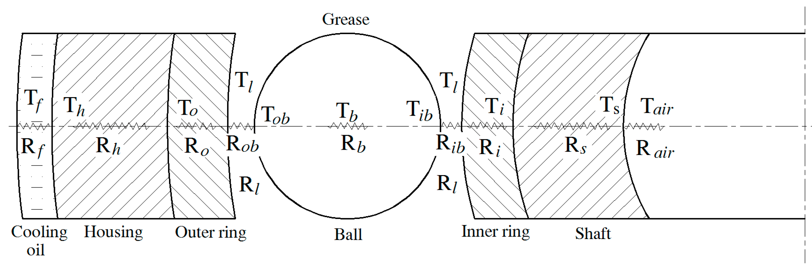
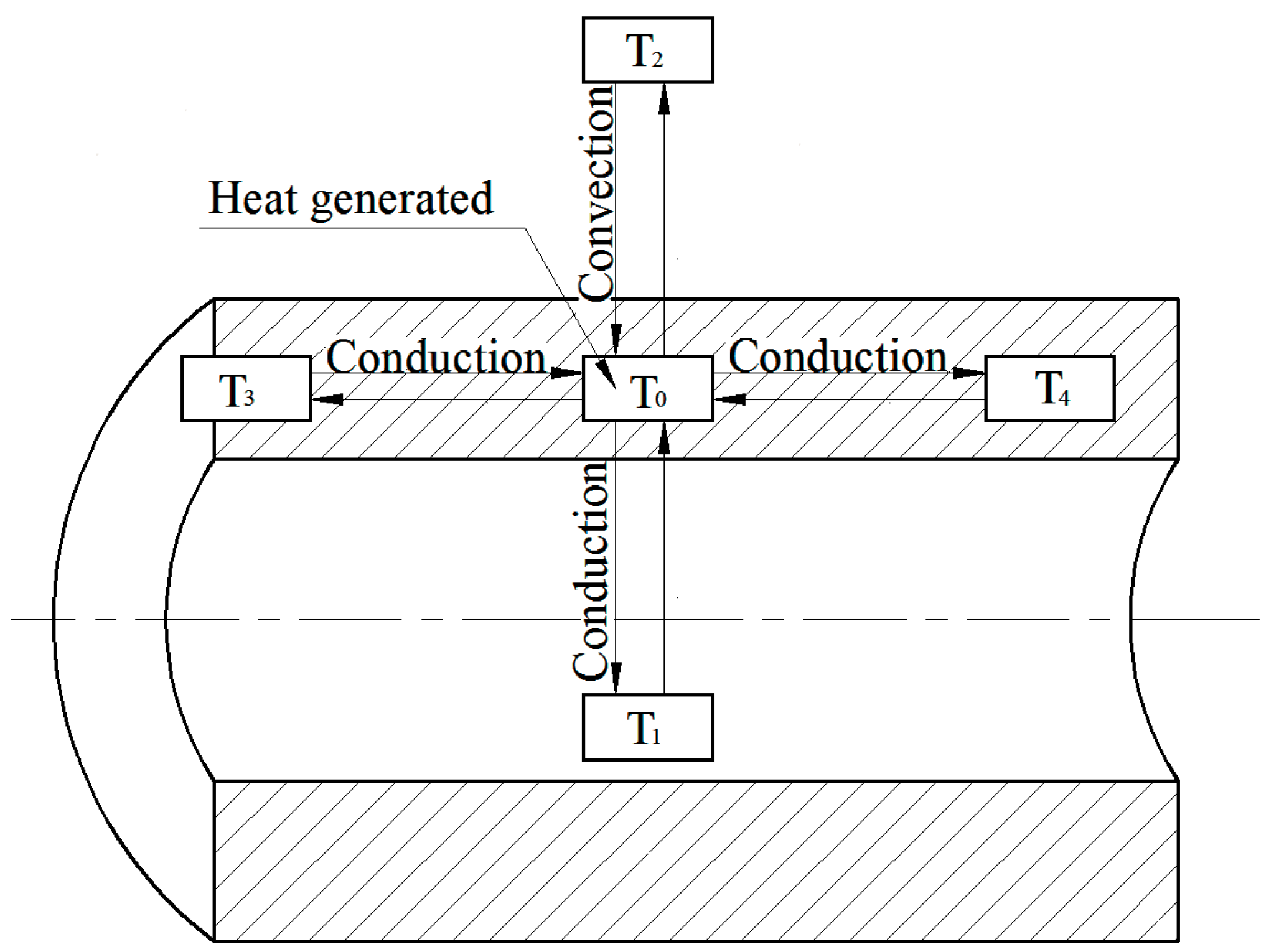
3. Heat Flow and Thermal Expansion Model

Three different heat transfer patterns characterize the spindle-bearing system studied in this paper: thermal conduction among the components and parts, heat convection between the components/parts and the fluid, and heat radiation among the separated objects in space. Since the normal temperature rise of the spindle system is about 30 °C, the corresponding heat radiation is relatively small, thus can be neglected. Due to the discontinuous structure of the spindle system, classical methods for heat transfer analysis are not suitable to analyze the system temperature. In the following section, the spindle system is discredited and key temperature nodes are selected. Then, heat balance equations of nodes are established and the temperature field is calculated.

3.1. Heat Transfer Model

The heat transfer process describes how heat flows from the heat source to other components of the spindle system. Because of the discontinuities of the spindle-bearing system structures, classical methods of heat transfer analysis cannot be applied to obtain a solution describing the system temperature. Instead, methods of finite difference as demonstrated by Dusinberre can be applied to obtain a mathematical solution [20]. In this approach, the spindle-bearing system is discretized into a set of isothermal elements represented by temperature nodes, as shown in Figure 4. The heat transfer model is mainly composed of the bearing housing, the cooling fluid, the cooling jacket, the bearing outer ring, the bearing rolling element, the bearing inner ring, the lubricating grease, the shaft, and the natural environment. The temperature node system is built for analyzing the heat transfer process and the temperature distribution of the spindle system. Figure 4 shows the main thermal network of the spindle-bearing system consisting of 18 temperature nodes, 10 radial nodes, and eight axial nodes. Figure 5 shows the thermal resistance and temperature model of the 10 radial nodes of the spindle-bearing system: node 1 represents the shaft, nodes 2–6 represent the spindle bearing, node 7 represents the housing (cooling jacket), node 8 represents the cooling fluid, node 9 represents the lubricating grease, and node 10 represents the ambient. Eight axial nodes represent the housing.
The heat transfer coefficients of the spindle system mainly include the heat conduction coefficients among the components, the convection heat transfer coefficients of the lubricating grease, the cooling oil, and the natural air. Heat conduction is the simplest form of heat transfer, expressed as a linear function of the temperature difference in solids. However, heat conduction of the micro contact between the rolling element in the spindle bearing and the raceway groove is relatively complicated [25]. The physical characteristic of the cooling oil determines the variability of the convective heat transfer coefficient, whereas the importance of the lubricating grease is not only reflected in the spindle bearing friction heat generation process, but also in the heat transfer state during the heat transfer process.
In the following subsections, mathematical formulas of thermal contact resistance between rolling element and raceway groove, heat transfer coefficients of lubricating grease and cooling liquid are analyzed. Mathematical formulas of thermal conduction coefficient between the outer ring and housing, thermal contact resistance between the inner ring and shaft, the heat transfer coefficient of a rotating sphere, and the convective heat transfer coefficient of the natural air are provided by references [16,20,26].

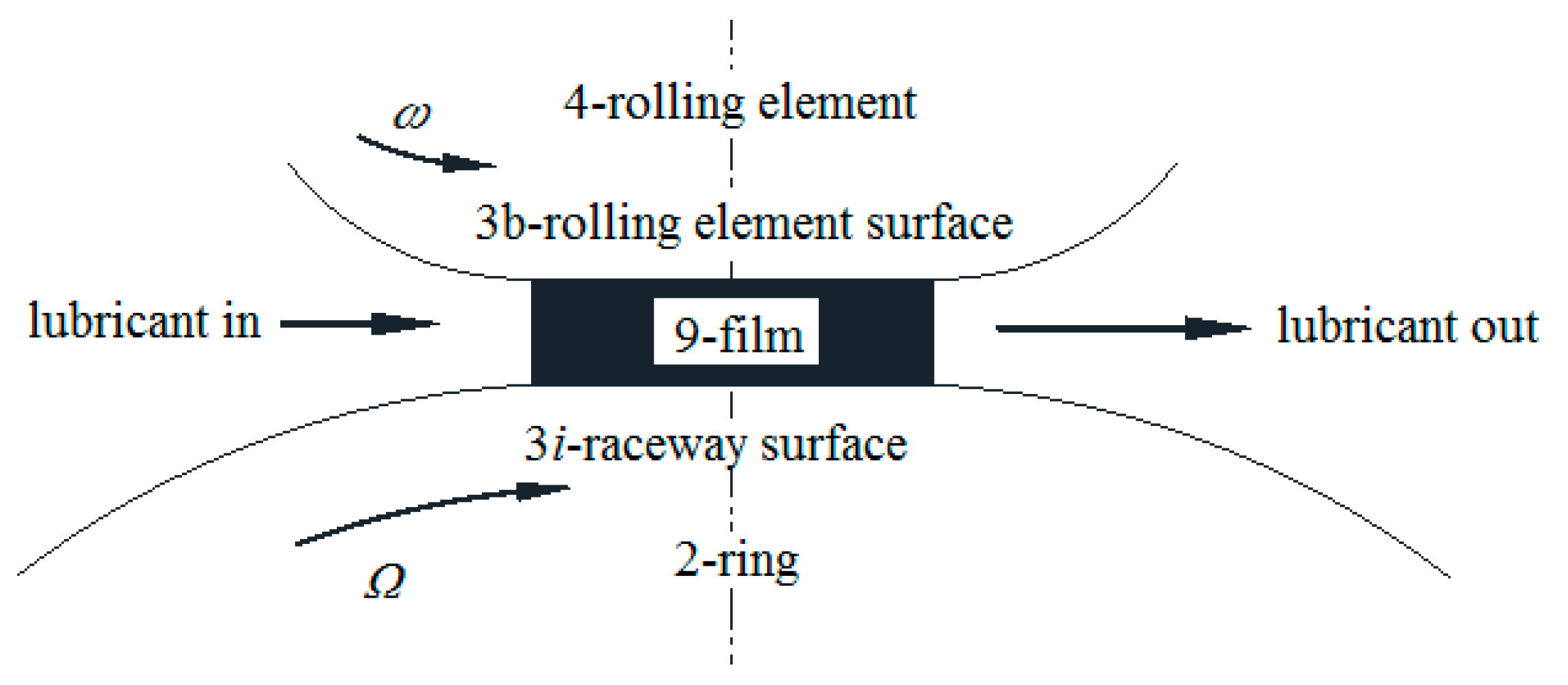
3.1.1. Thermal Contact Resistance between Rolling Element and Raceway Groove

The friction heat generation occurs in a very small elliptic contact area whose size affects the thermal contact resistance and thus is related to the geometric parameters of the bearing and the contact stress. For most of the bearings, the rolling element and the inner and outer rings are made of the same materials. Moreover, the thermal contact resistance between the rolling element and the inner and outer raceway grooves of the bearing have the same pattern. Therefore, the thermal contact resistance between the rolling element and the inner and outer raceway grooves can be expressed as [25]:
R n b = ψ ( a / b ) 4 k a ,
where k is the heat conductive coefficient and ψ(a/b) can be written as:
ψ ( a / b ) = 2 π 0 π / 2 d θ [ 1 ( 1 b 2 / a 2 ) 2 sin 2 θ ] .
Then the thermal contact resistance of each rolling element becomes:
R b = 1 2 k [ ψ ( a o / b o ) a o + ψ ( a i / b i ) a i ] .

3.1.2. Heat Transfer Coefficient of Lubricating Grease

Eckert provides the rough approximation formula for the surface heat transfer coefficient of high viscosity grease [20]:
h l = 0.332 k P r 1 3 ( u m ν x ) 1 2 ,
where k is the heat conductive coefficient of the lubricating grease, um is the relative velocity between the grease and the rolling element, x is the pitch diameter of the bearing, ν is the kinematic viscosity of the grease, and Pr is the Prandtl number of the grease.

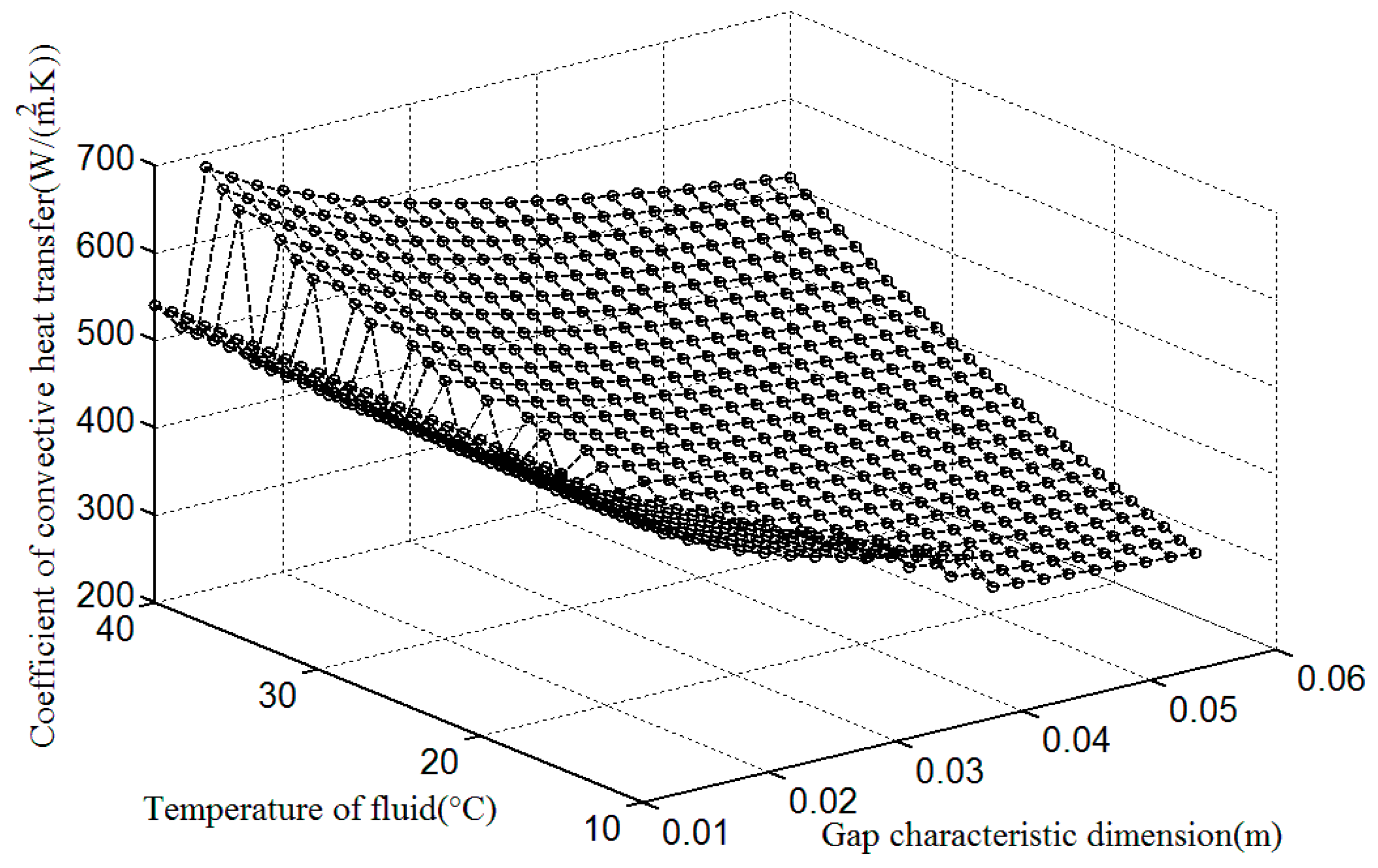
3.1.3. Convective Heat Transfer Coefficient of Cooling Oil

The spindle bearing friction heat must be effectively taken away from the bearing, otherwise abnormal high temperature will arise, or even the thermal failure phenomenon will appear. Therefore, a spindle bearing is usually designed to coordinate the installed cooling jacket in the spindle system, which is used to enforce convection heat transfer on the spindle bearing and thus realize the temperature rise control of the spindle system.
According to the Nusselt criterion, when the cooling oil is under the conditions of turbulent flow state, the convective heat transfer coefficient can be calculated as follows:
h f = 0.0225 k h g a p R e 0.8 P r 0.3 ,
where k is the heat conductive coefficient of the cooling oil, hgap is the equivalent diameter, Re is the Reynolds number, and Pr is the Prandtl number.
Under the conditions of a laminar flow state, the convective heat transfer coefficient can be calculated according to the following formula:
h f = 1.86 k h g a p ( R e P r h g a p L ) 1 3 ,
where L is the feature size.
When the average flow velocity of the cooling oil is determined, the Reynolds number and the Prandtl number of cooling tank with any cross-sectional shape can be defined as:
R e = u h g a p ν       P r = c η k ,
where u, ν , c, and η are the flow rate, the kinematic viscosity, the specific heat capacity, and the dynamic viscosity of the cooling oil, respectively.
Conduction through the mating surfaces of the outer ring and housing is modeled as a function of temperature-related clearance fit; the equivalent permissivity is proposed by Bossmanns [16]. Thermal contact resistance between the inner ring and shaft is proposed by Teng Hu [26]. The coefficient of convection heat transfer for a rotating sphere is provided by Harries [20]. Many experimental researches and FE analyses on convective heat transfer between the spindle system and the natural air have been carried out. Due to the structural complexity of the spindle system, scholars preferred to obtain the convective heat transfer coefficient by experimental measurements. In this paper, the existing research results [16] are considered and the convective heat transfer coefficient of the natural air is taken as a stable value of 9.7 W/(m2·K).

3.2. Temperature Distribution

Eighteen temperature nodes were selected as the heat transfer system, the initial boundary conditions, and the initial temperatures are set, to analyze the spindle system heat transfer model. Considering the complexity of the calculation process, it is assumed that 18 temperature nodes sufficiently describe the system. Meanwhile, it is also assumed that the temperature of the inner and outer ring raceway grooves is uniform. The temperature nodes system consists of coaxial, cylindrical pipe elements, such as the one shown in Figure 6. The general form of energy balance for any temperature node is [16]
H f 0 + H 1 - 0 , c + H 2 - 0 , v + H 3 - 0 , c + H 4 - 0 , c = m 0 c T t .
Take the lubricating grease film (node 9) as an example, as shown in Figure 7; the inlet temperature of the grease film is T9-in, the outlet temperature is T9-out and the oil film temperature is T9. Its neighboring temperature nodes are the inner ring 2 of the bearing, the contact area 3 of the rolling element with the inner raceway groove, and the rolling element 4.
The governing equation of temperature node 9 can be expressed as:
H f + H c , 3 b - 9 + H c , 3 i - 9 + ω c ( T 9 - o u t T 9 - i n ) = m 9 c 9 T 9 t ,
where Hf is the friction heat generation, Hc,3i-9 is the heat transferred by thermal conduction between the contact surface of the rolling element and the lubricant grease film, Hc,3b-9 is the heat transferred by thermal conduction between the contact surface of the inner raceway groove and the lubricant grease film, ω is the rotational speed, c is the specific heat capacity of the lubricating grease, and m is the quality of the lubricating grease.
In this temperature node system, the other energy equations are determined as
H c , 3 b - 4 + H v , 9 - i n - 4 = m 4 c 4 T 4 t H c , 4 - 3 b + H c , 9 - 3 b = m 3 b c 3 b T 3 b t H c , 9 - 3 i + H c , 2 - 3 i = m 3 i c T 3 i t H c , 3 i - 2 + H v , 9 - i n - 2 = m 2 c 2 T 2 t H v , 2 - 9 - o u t + H v , 4 - 9 - o u t ω c ( T 9 - o u t T 9 - i n ) = m 9 - o u t c 9 - o u t T 9 - o u t t .
The form of Equation (18) can be shown as
H f + T i b T 9 R i b + T b i T 9 R b + ω c ( T 9 - o u t T 9 - i n ) = m 9 c 9 T 9 t ,
where Rib is the thermal contact resistance of the rolling element surface, Rbi is the thermal contact resistance of the inner raceway groove surface, Tib is the contact surface temperatures of the rolling element, and Tbi is the inner raceway groove.
Using the thermal balance of all the temperature nodes of the spindle system, 18 equations can be listed, similar to Equation (20), and the heat transfer system of the temperature nodes are given in Table B1 in Appendix B, including 18 unknown temperatures. The Newton–Raphson method is used to solve this nonlinear equation. Firstly, initial temperatures need to be assumed based on experience. The lubricating grease viscosity is determined, and the friction heat generation of the spindle bearing is calculated according to Equations (1) and (9); then, the heat transfer coefficients are calculated; finally, the node temperatures are obtained. This process is iterated until the calculated temperatures match the known experimental measurements. During the calculation process, the boundary conditions and the initial system temperature can be re-adjusted in order to make the calculation results more accurate.

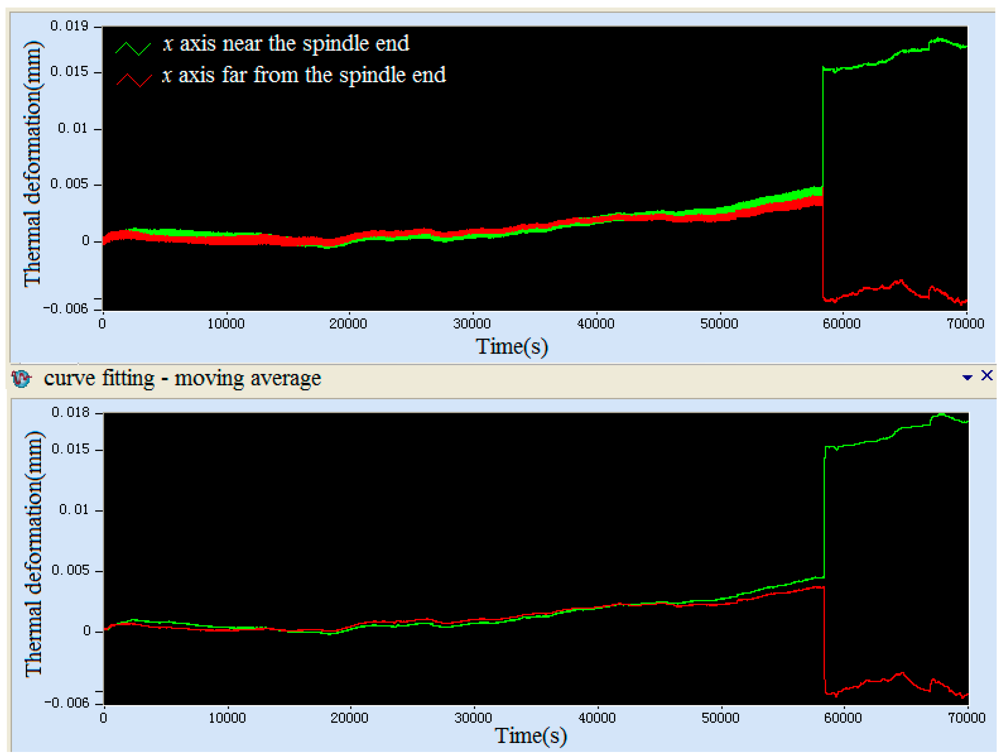
3.3. Thermal Deformation

Bearing preload is normally considered as a combination of initial preload and thermally-induced preload [27,28,29]. The initial preload is provided by SKF bearing technology manual in this paper. The thermal preload is associated with the uneven expansion of the spindle-bearing system components, because of the temperature gradient due to frictional heat generation in the bearings. During the operation, as the temperature of the spindle assembly increases, components of the spindle experience different thermal expansion rates due to differences in their temperature rise and geometry structure. As a result, the initial interference at the spindle assembly is affected, leading to changes in the thermally-induced preload. The thermally-induced preload is not easily measurable because of the major difficulties in installing sensors inside the spindle [30]. Nevertheless, indirect techniques to estimate the bearing preloads by measuring the induced strain on the shaft or housing in contact with the bearings is presented by Stain [29] and Kim [31].
The thermally-induced preload can affect the frictional moments as well as the heat generation rate according to Equations (4) and (5). Thermal failure can occur due to a rapid increase of the thermally-induced preload, if the heat generation rate exceeds the rate of heat dissipation from the bearing. Usually, the outer ring and the spindle housing are clearance fit, while the inner ring and the rotating shaft are interference fit, so appropriate formulas must be used.
The thermal deformation of the hollow shaft in any radial position r can be obtained from Love’s displacement equation [32]:
u r = 1 + ξ 1 ξ Γ r 0 r Δ T ( r ) r d r + D 1 r + D 2 r ,
where
D 1 = ( 1 + ξ ) ( 1 2 ξ ) 1 ξ Γ r o 2 r i 2 r i r o Δ T ( r ) r d r ξ k z . u r = 1 + ξ 1 ξ Γ r i 2 r o 2 r i 2 r i r o Δ T ( r ) r d r ,
where ro is the outer radius of ring, ri is the inner radius of ring, and Г is the thermal expansion coefficient.
When axial deformation is considered,
k z = 2 Γ r o 2 r i 2 r i r o Δ T ( r ) r d r ;
in the other case, kz = 0.
Next, the thermally-induced preload is estimated by the Hertzian contact theory according to the following equation [8]:
F r = k r u r n ,
where n is taken to be equal to 1.5 for ball bearing, and kr is a coefficient for the radial elastic contact of the bearing.
The radial compound stress-deformation equation under the initial preload, centrifugal force, and thermal-induced preload was derived following the thermo-elasticity theory [32]:
d 2 u d r 2 + 1 r d u d r u r 2 = 1 + ξ 1 ξ Γ d ( Δ T ) d r ( 1 + ξ ) ( 1 2 ξ ) E ( 1 ξ ) ρ ω 2 r .
This differential equation can be solved by integrals, and the total radial deformation can be obtained; it can be used for contrastive analysis of numerical and experimental result, in order to verify the accuracy of the theoretical model.

4. Result Analysis and Discussion

The structure of the high-power precision spindle used for the experimental research in this paper has been described in Section 2.The maximum rotational speed of the spindle was 5000 rpm, the power is 37 kW, corresponding to 1.1 million DN with a 165 mm bore diameter of the spindle bearings, and the ball diameter is 13.37 mm. All the tests were carried out in a controlled temperature room at 20–25 °C and a relative humidity of 20%–25%. In this section, the effectiveness, accuracy, and practicability of the thermo-mechanical coupling model, heat transfer model, and temperature distribution prediction are validated through a comparison of experimental results and theoretical results. Meanwhile, the effect of main parameters on the mathematical models of friction heat generation, the heat transfer coefficient, and the temperature prediction are discussed and analyzed. The thermal failure is also discussed and defined in this section.

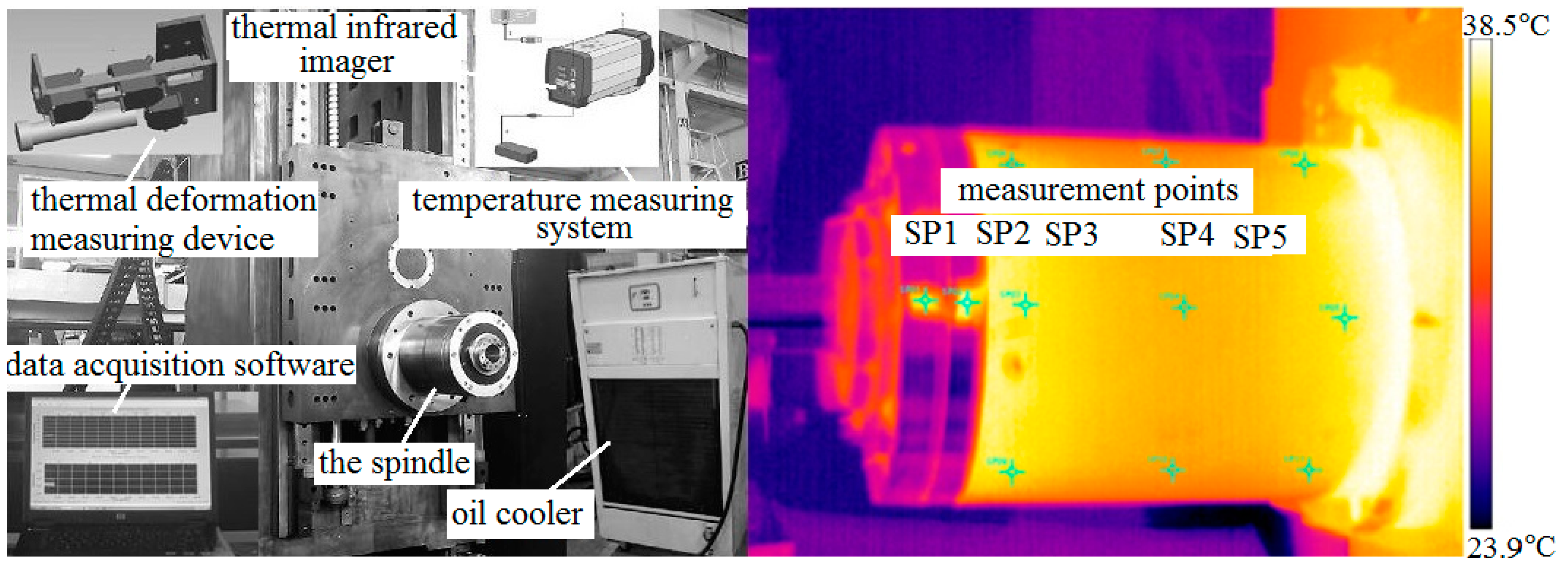
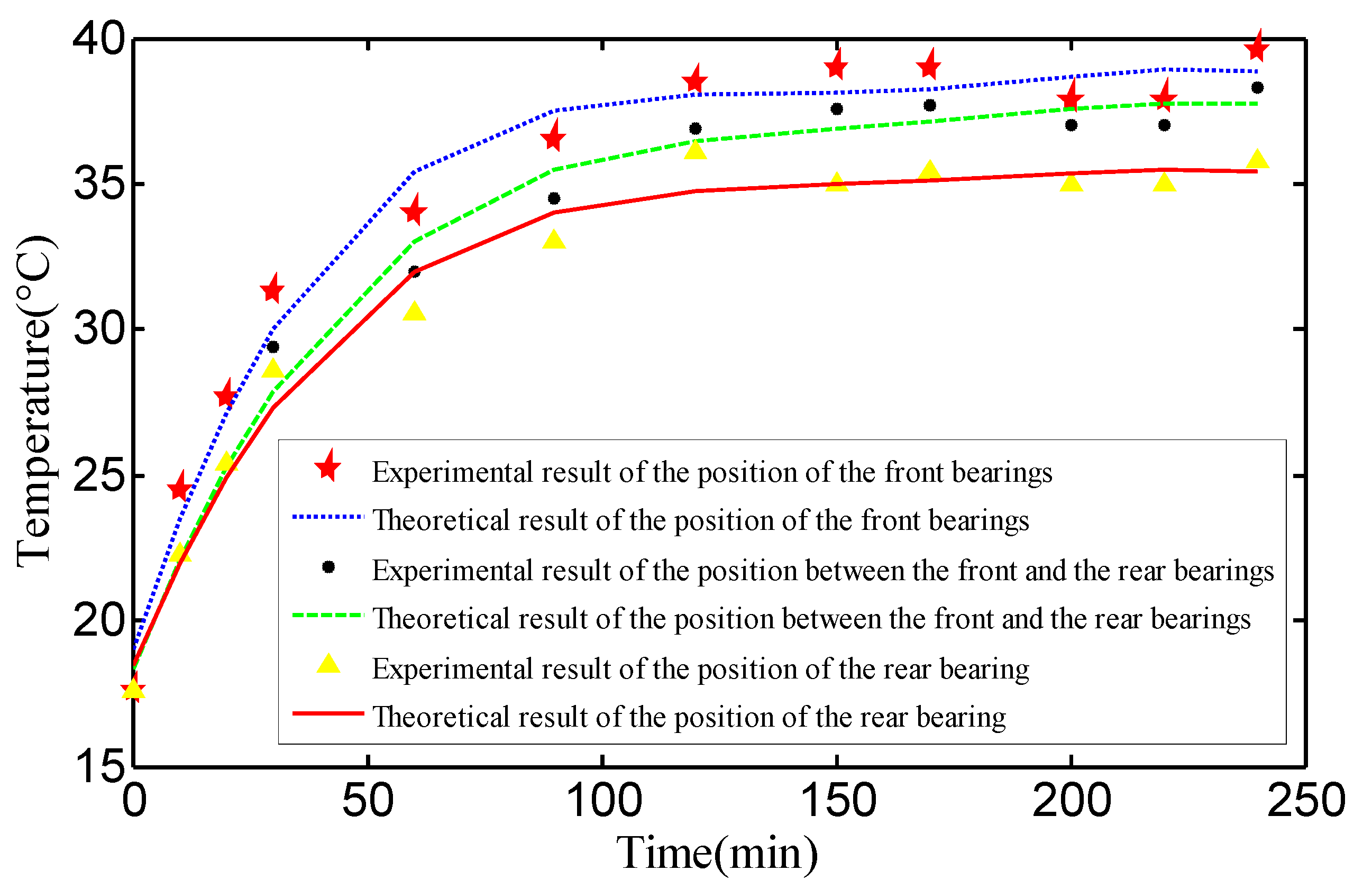
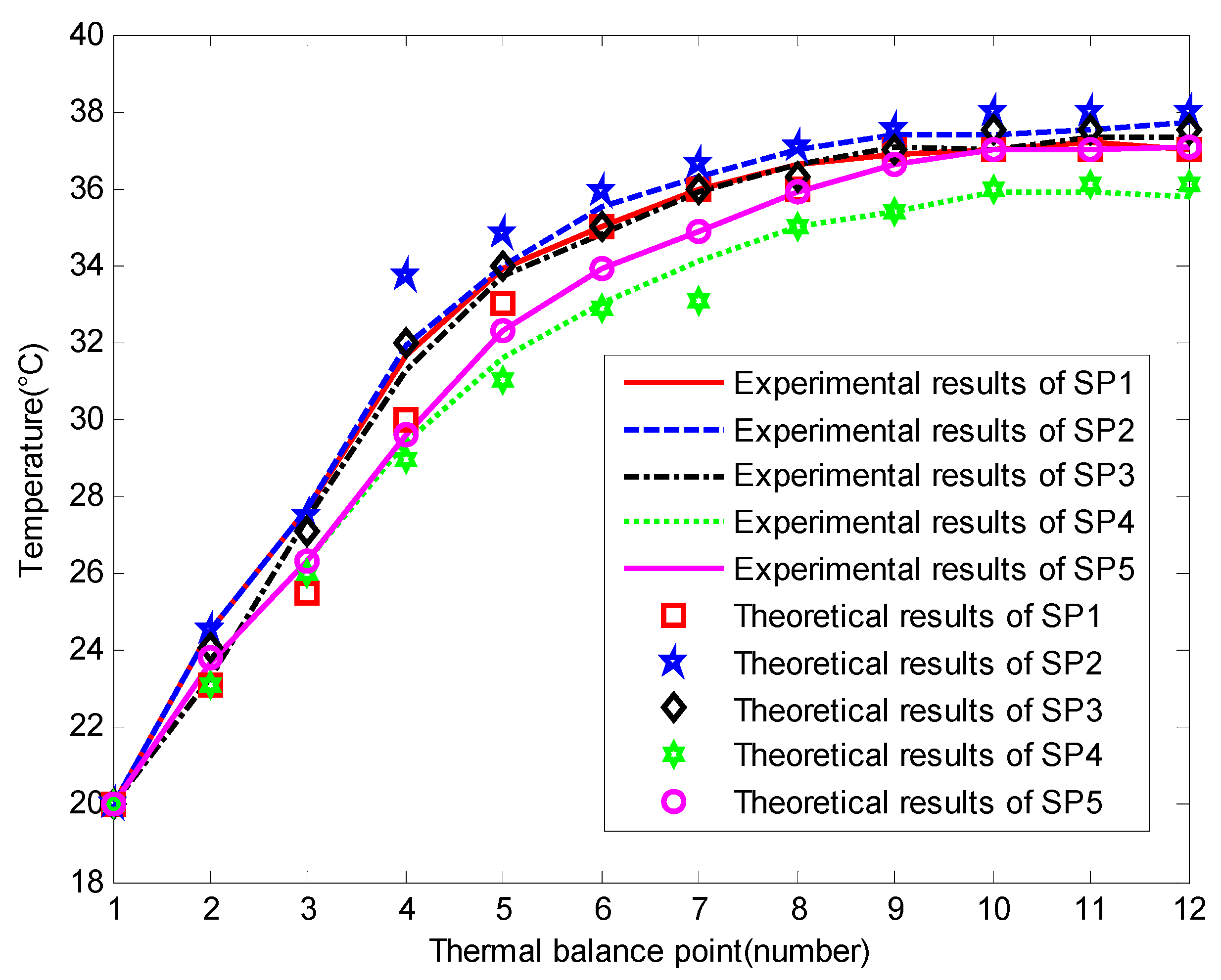
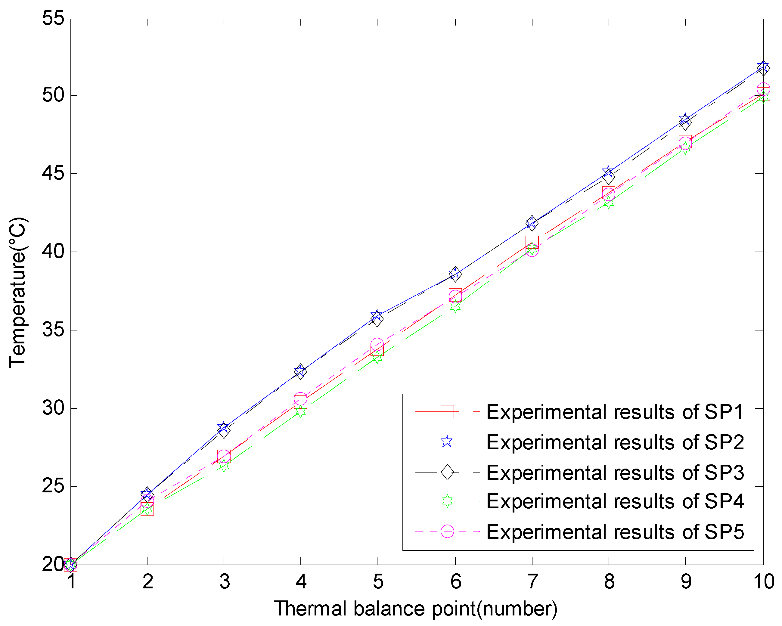
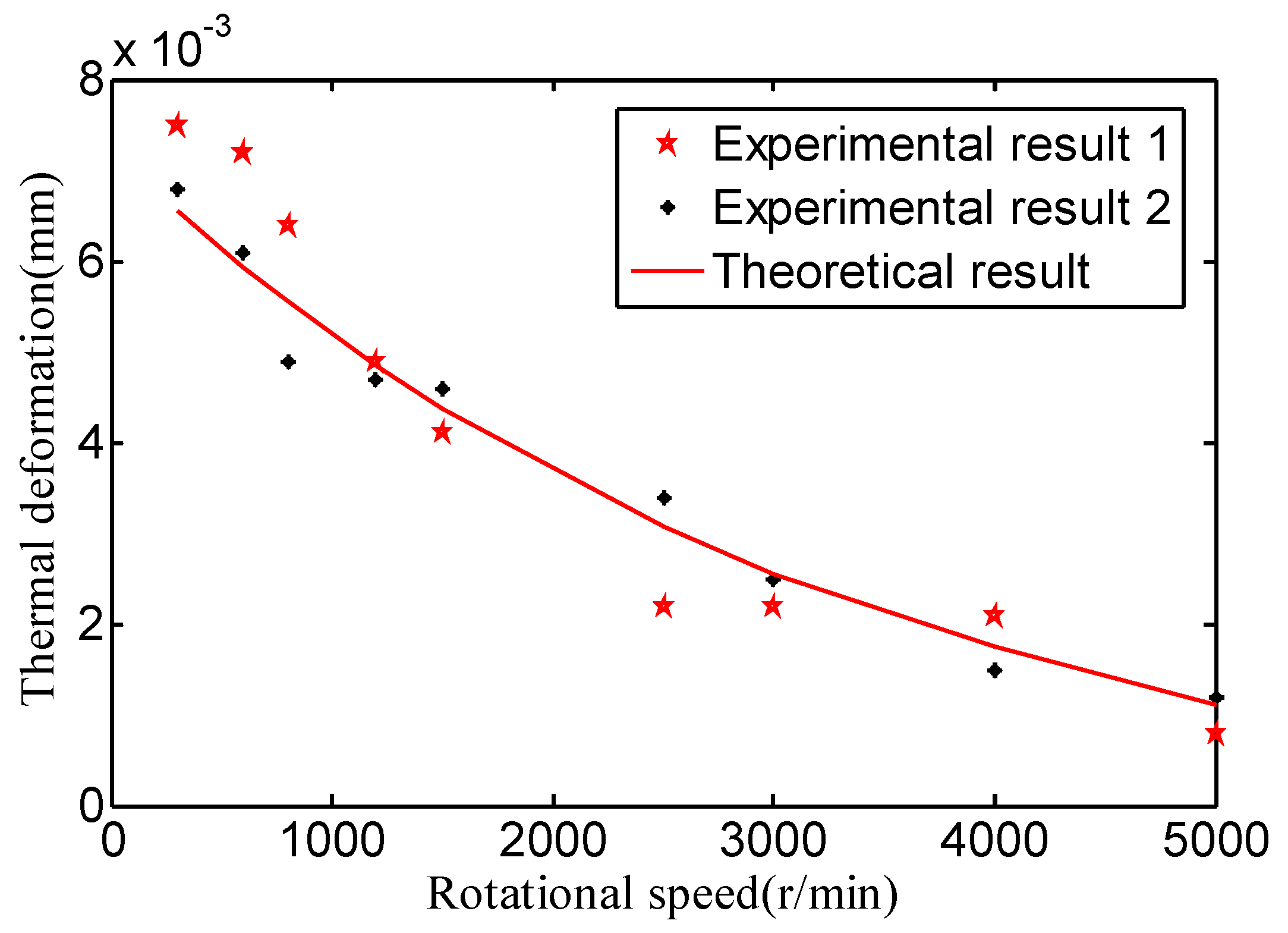
4.1. Experimental Verification

Figure 8 shows the experimental measuring equipment of the spindle system. The transient temperature field of the spindle was measured by a FLIR thermal infrared imager (FLIR Systems, Boston, MA, USA) and a PC was used to collect and process the data; the transient thermal deformation of the spindle was measured using five Micro-Epsilon laser triangulation sensors (MICRO-EPSILON, Ortenburg, Germany) and a IF2004 data interface card (MICRO-EPSILON, Ortenburg, Germany). The spindle cooling system used a HABOR oil cooler, model is HBO-3RPTSB-BY-10, (HABOR, Taiwan). Its oil temperature could be controlled within the range 10–40 °C and the initial oil temperature was set to 15 °C. Transient temperature measuring points (SP1 to SP5, respectively) were selected on the rotating shaft. Because the thermal infrared imager is sensitive to the reflectivity of the measured object surface, adhesive tape needed to be stuck on each point to reduce the surface reflectivity.
In each experiment, first, an adjustable ring and torque spanner are used to provide axial force for the bearing; next, the motor speed is gradually increased to the desired experimental value. All experiments are continued until the steady state condition of the spindle system is attained. Four hours were required for the transient temperature and thermal deformation measurements. The steady state appears at about three hours; afterward, the temperature is relatively stable. The experiment continued for one hour in the steady state before shutting down the motor. Measurement of the temperature continues until the spindle cools down to the ambient temperature in the constant temperature workshop.
The experiments are purposefully designed to validate the mathematical models in Section 2 and Section 3 and the effect of three important parameters, namely speed, preload, and the temperature of the cooling system. The spindle system was operated under 350 N or 1750 N preload, which is provided by different adjustable rings. Rotational speed can be increased from 0 rpm to 4500 rpm, step-by-step (step length of 500 rpm). The temperature of the cooling system can be changed from 15 °C to 40 °C. Each time one test parameter is kept constant and separate tests are carried out for different values of the other parameters.
The results of the experiments are presented and compared with the predictions based on the mathematical model in Section 2 and Section 3. Comparisons of the theoretical results and experimental results are shown in Figure 9 and Figure 10. Figure 9 shows the comparison of the measured and predicted housing temperature. The measuring points are SP1–3, the tests are continued for 250 min, the rotational speed is 3000 rpm, and the preload is 1750 N. A maximum of three degrees of discrepancy in the transient state condition is considered acceptable.
Figure 10 shows the comparison between experimental and theoretical predicted temperatures in steady states. The experiment includes 11 steady states from 500 rpm to 4500 rpm. After the spindle reaches the steady state at the constant rotational speed, the temperature values of the five measuring points were recorded; after the temperature data collection is done the rotational speed can be increased by 500 rpm for the next test. Finally, experimental results and calculated values were compared and analyzed. Points 1–10 are the steady states temperatures of the measuring points that correspond to 0–4500 rpm (the step is 500 rpm); 10–12 are the temperatures of the measuring points that correspond to 4500 rpm. This experiment time is 44 hours. The difference between the measured values and the theoretical values is 2.5%, a reasonable error range. The maximum temperature difference of 3 °C appears at the steady state of 1500 rpm.
The main factors affecting the accuracy of the theoretical model include the setting of boundary conditions and the initial temperatures, and the complexity of the lubricating state. Figure 9 and Figure 10 show the validity of models for predicting temperature distribution in the transient state as well as the steady state. Therefore, the mathematical models presented in this paper can be used to analyze the effect of the main parameters of the spindle system on thermal characteristics, and can be applied to further research and development of a spindle-bearing system.

4.2. Numerical Analysis

The main parameters of friction heat generation in the spindle-bearing system are the surface friction shear stress and the sliding velocity of the rolling element. Surface friction shear stress depends on the oil film thickness of the lubricating grease, the viscosity of the lubricating grease, the normal contact stress, and the surface morphology. Moreover, the main parameters of the rolling element are the rotational speed and the contact angle. In the spindle system, the main factors affecting the heat transfer model are the heat transfer coefficient of the lubricating grease, the thermal contact resistance between the rolling element and the raceway, and the heat transfer coefficient of the cooling system. The heat transfer coefficient of the lubricating grease and the cooling system is mainly determined by their own temperature, whereas the thermal contact resistance between the rolling element and the raceway is mainly determined by the normal contact stress. In this section, the main factors affecting the thermal characteristics of the spindle-bearing system, such as the rotational speed, the preload, the lubricating grease, and the cooling system, are discussed and analyzed.

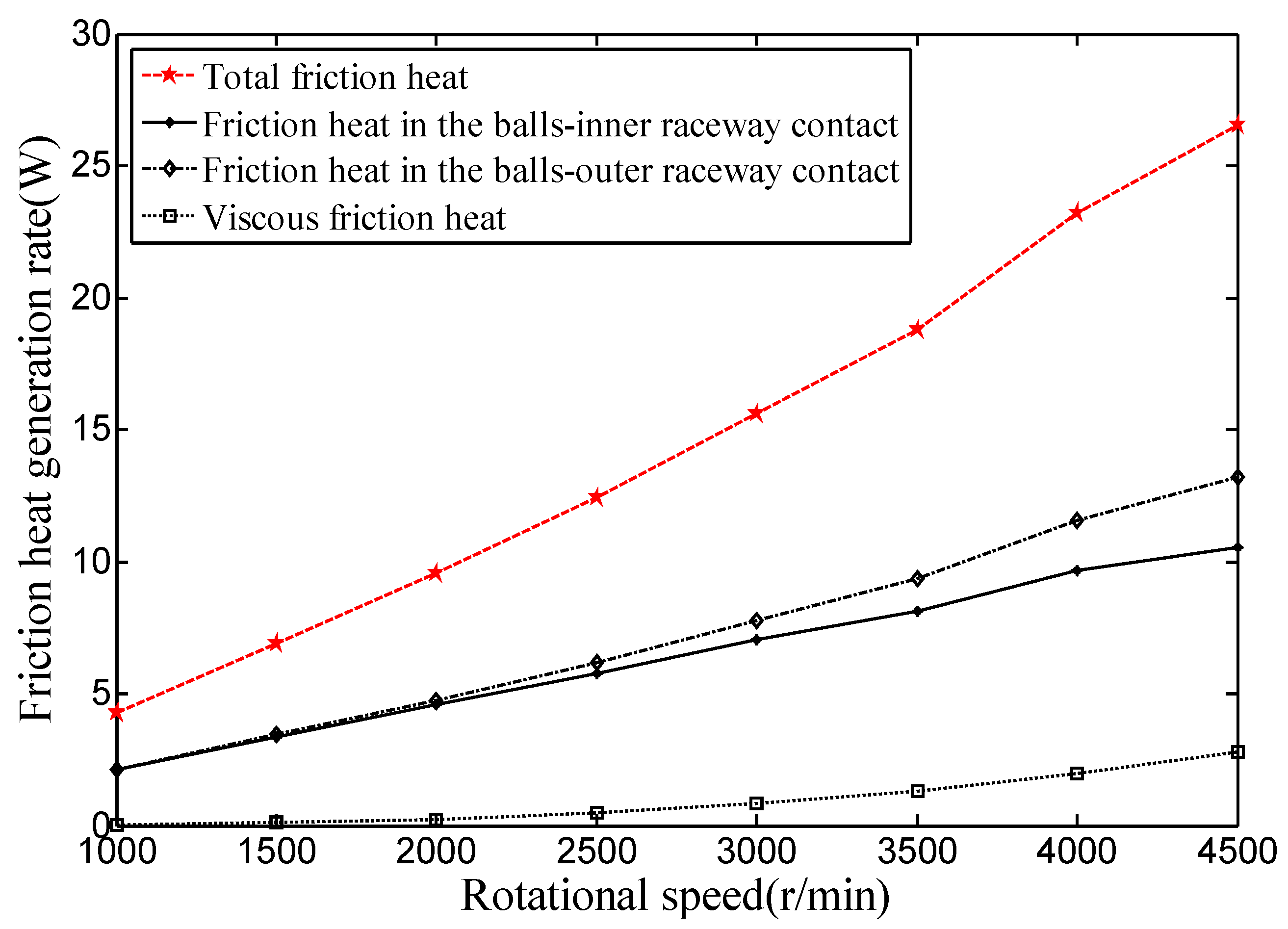
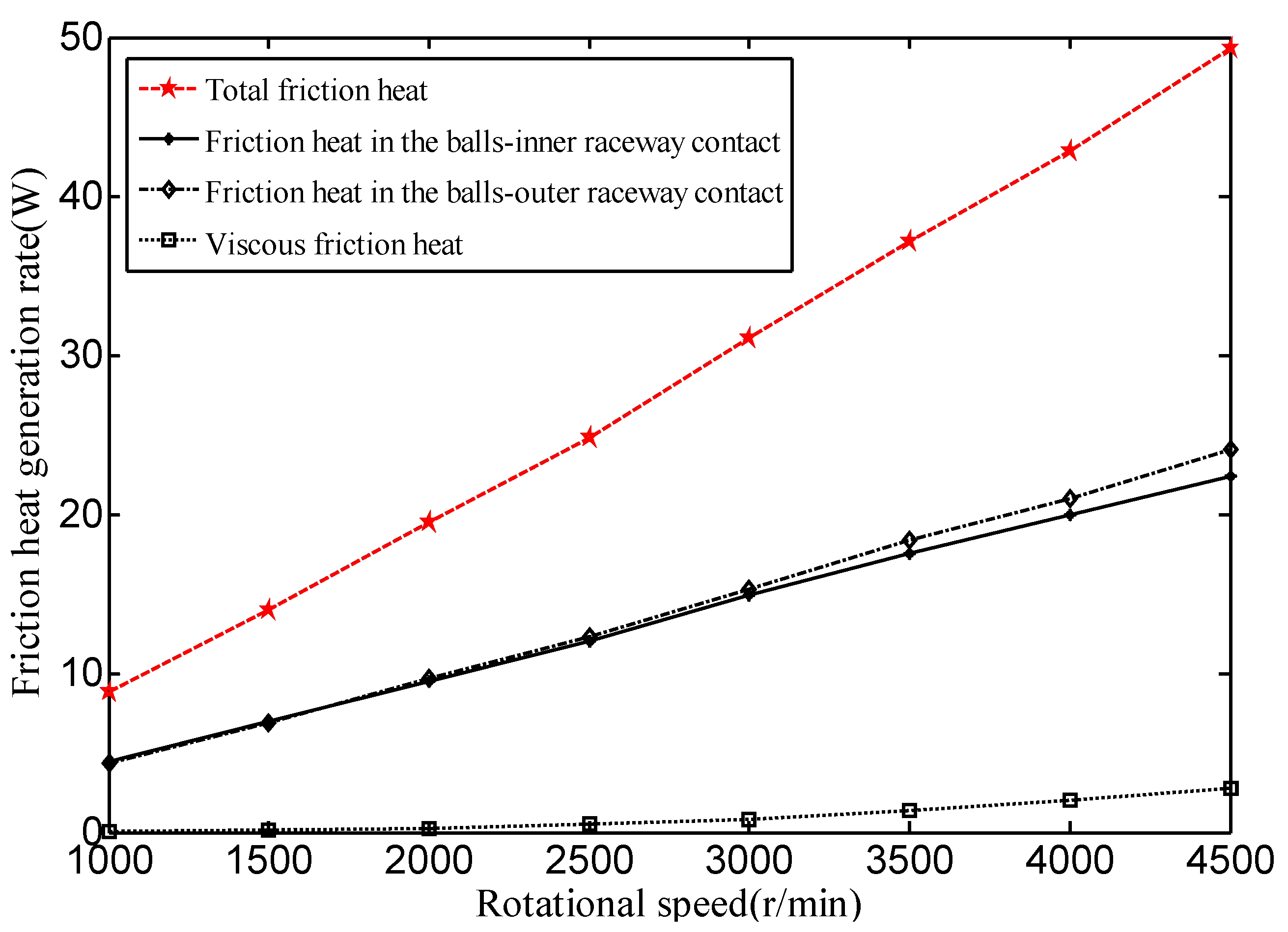
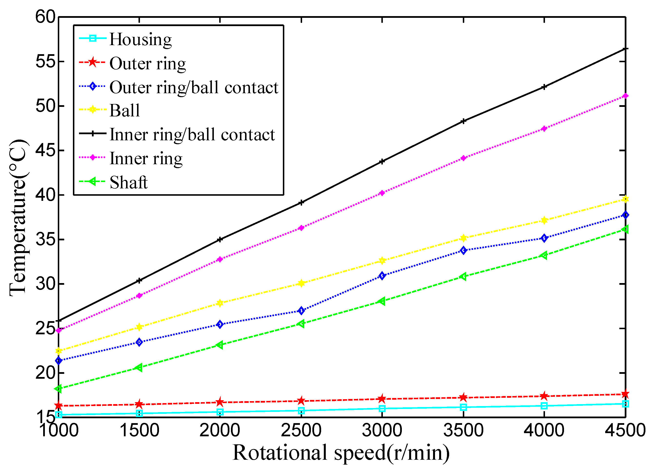
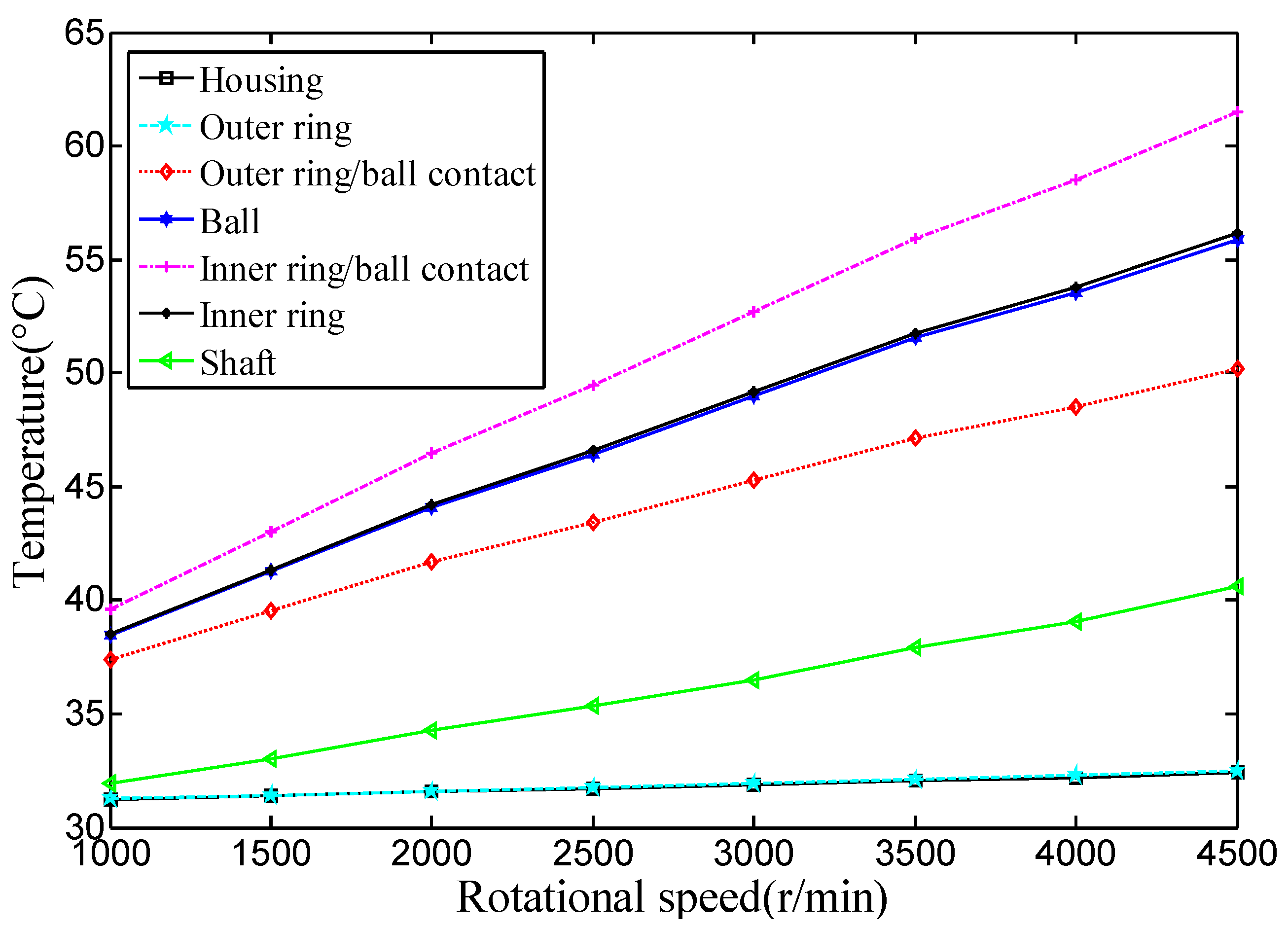
4.2.1. Effect of Rotational Speed and Preload

Figure 11 and Figure 12 show the friction heat generation of the spindle bearing at different rotational speeds with a constant preload of 350 N and 1750 N. As seen at a constant preload, the spindle bearing friction heat increases steadily with the increase of the rotational speed. Theoretical calculations show that the rotational speed determines the centrifugal force and the gyroscopic moment of the spindle bearing, which is also the main parameter for calculating the sliding velocity of the rolling element. Therefore, rotational speed has a large effect on friction heat generation. Moreover, the experimental monitoring process shows that the instantaneous increase of the rotational speed will lead to an instantaneous peak in a short time of temperature rise. If the cooling rate and the heat generation rate cannot achieve a balance in a certain time, thermal failure of the spindle system may appear [8].
Although the centrifugal force and the gyroscopic movement caused by the spindle rotational speed could lead to in of the contact stress and the contact angle, the initial preload is the main parameter of the spindle system. The comparison between Figure 10 and Figure 11 shows that the preload increase will inevitably lead to an increase in the friction heat generation. When the temperature rises due to the friction heat generation, the thermally-induced preload will appear. Based on Equation (24), thermally-induced preload is proportional to thermal deformation. Takabi [7] showed that the predicted thermally-induced preload increases rapidly during the first 400 s of operation, and then gradually decreases to zero after 2250 s, but this behavior is dependent upon the bearing configuration and operating conditions. Figure 13 shows radial thermal deformation measured during an experiment with constant speed of 3000 rpm. As seen, the thermal deformation of the shaft rapidly increases during the first eight minutes, then decreases to a very small value after 66 min, then gradually increases to 0.003 mm; finally, when the operation is finished, in the process of reducing the speed of the spindle, the thermal deformation appears to increase. The main reason is that the temperature gradient among the spindle components changed quickly. The rapid increase of thermally-induced preload is the main cause of spindle bearing thermal failure [27,28,29].
Rotational speed and preload are the two main parameters in the theoretical calculation of friction heat generation. Therefore, in the actual operational conditions of high speed and low load, or low speed and high load, thermal failure of the spindle system may happen. During the research and development process of a precision spindle, detailed analysis and calculation of the rotational speed and the preload must be carried out to avoid the premature appearance of thermal failure and prolong spindle bearing life [8].

4.2.2. Effect of Lubricating Grease Temperature

KLUBER/NBU15 (Freudenberg Group, Weinheim, Germany) grease is used to lubricate the spindle bearing. The kinematic viscosities of grease are 21 mm2/s at 40 °C and 4.7 mm2/s at 100 °C, respectively. The density of grease is 0.99 g/cm3. The relationship between kinematic viscosity, temperature, and pressure is expressed by Roelands as follows [20]:
η ( T , p ) = η 0 exp { ( ln η 0 + 9.67 ) [ ( 1 + 5.1 × 10 9 p ) 0.68 × ( T 138 T 0 138 ) 1.1 1 ] } .
Assuming that the density of the lubricating grease is constant, the dynamic viscosity is linearly proportional to the kinematic viscosity, and hence the grease viscosity is a function of temperature and pressure. The grease temperature obtained by experimental measurements and the lubricating oil film thickness can then be calculated [20]. Figure 14 shows a comparison of central oil film thickness in the isothermal state and the thermal effect on the grease. As seen, center oil film thickness gradually increases with the increase of the rotational speed, especially at high speed; if the oil film thickness increases 2 to 3-fold, the friction shear stress will change greatly, leading to a non-ignorable effect on friction heat generation.
Calculation accuracy of oil film thickness and the friction drag force is determined by the grease viscosity at the current temperature. Meanwhile, the oil film thickness and the friction drag force are also main parameters for calculating the friction heat generation. In the calculation of friction shear stress, it is important to determine grease viscosities at the appropriate temperature. For calculation accuracy, it is necessary to estimate the grease temperature at the entrance to each contact and in the film separating the rolling/sliding components [20]. Therefore, the effect of grease temperature on the friction heat generation of the spindle system is significant. During the analysis of the main operating conditions of the spindle system, if the predictive operation temperature of the lubricating grease is too high, it is generally necessary to cool the lubricant and permit the lubricant to cool the bearing, but this method will make the spindle structure complex.

4.2.3. Effect of Cooling System

An experimental scheme was designed without considering the cooling system. Using transient temperature monitoring, the temperatures of measuring points from 0 to 4500 rpm with a step length of 500 rpm were obtained as shown in Figure 15. When the rotational speed was within the range 0–3000 rpm, the temperatures were collected when the spindle reached the steady state after 4 h. Within the range 3500–4500 rpm, temperatures were collected after the spindle running for half an hour. The comparison between Figure 10 and Figure 15 shows that the temperature rise of the spindle system is far greater when the cooling system does not work than when the cooling system is working.
Based on the principle of processing technique optimization, the cooling system of the spindle is generally via a helical rectangular oil-cooling channel. In this paper, the cooling oil is ISO VG32. Based on experimental data, the relationship between the physical characteristic and the temperature can be obtained:
k = 0.1381 ( 1.012 5.5018 × 10 4 t ) ρ = 869.1 [ 1 7.9744 × 10 4 ( t 21 ) ] η = 0.06673 e 0.051 ( t 21 ) c p = 4.428 ( t 21 ) + 1884.2 .
The heat transfer capability of the cooling system is related to the cooling oil temperature, the cooling oil flow, and the equivalent diameter of the cooling channel. The cooling oil flow is selected as the maximum flow, and then the relationship of the heat transfer coefficient of the cooling system, the cooling oil temperature, and the equivalent diameter of the cooling channel are analyzed [33,34]. The cooling oil temperature was selected from 10 °C to 40 °C, and the equivalent diameter was selected from 0.01 m to 0.06 m; this range is analyzed by FEA and it satisfied with the structure strength. Then, by substituting Equation (27) into Equation (14) or Equation (15), the heat transfer coefficient of the cooling system is obtained, as shown in Figure 16.
The initial temperature of the cooling system is 15 °C; the radial temperature distribution of the spindle system could be obtained based on the heat transfer model, as shown in Figure 17. The radial temperature gradient of the spindle system is very large, and the heat dissipation rate of the outer ring is far greater than that of the inner ring of the bearing, which has a risk of temperature deflection. The substitution of the convective heat transfer coefficient interval of the cooling system into the heat transfer model and the large number of numerical calculations make the heat transfer path guarantee that the temperature gradient through the spindle bearing does not create thermal deflection.
The convective heat transfer coefficient interval of the cooling system is about 200–700 W/(m2·K). When the convective heat transfer coefficient of the cooling system was 520.89 W/(m2·K), the corresponding radial temperature distribution of the spindle system could be obtained as shown in Figure 18. Compared with Figure 17, although the temperature of the inner raceway groove in the bearing increases by about 3 °C, the radial temperature difference of the spindle system can be controlled under 30 °C even at the highest rotational speed. Moreover, the whole spindle system can reach a thermal balance state after 2.5 h, which meets the temperature control requirement of the spindle system. Meanwhile, the analysis of the cooling system highlights that the convective heat transfer coefficient is not “the bigger the better” and the temperature of the cooling oil is not “the lower the better.” Carmichael and Davies [8] reported an excessively high thermally-induced preload inside the roller bearing for the case of water cooling of the housing, which can lead to the thermal failure of the roller bearing. Conversely, Chun [8] showed that the cooling of the shaft can considerably reduce the thermally-induced preload in the bearing. This shows that if the analysis is not accurate, it can also lead to the thermal failure of the spindle system [19].
Figure 19 shows the effect of the optimization cooling system on the thermal deformation of the inner ring. Thermal deformation was measured during two experiments at different speeds, and also collected in the steady state. As seen, the thermal deformation of the inner ring decreases rapidly from 1000 rpm to 5000 rpm. The optimization cooling system is very useful for the thermal balance of the high speed spindle, and it also can decrease the temperature at the steady state.
In cooling system design, the design variables—channel geometry, temperature of fluid, entropy generation, maximum temperature distribution of the spindle-bearing system, and oil cooler work—are chosen as the objective function [34]. Considering different design requirements, we will research a multi-objective optimal design method to obtain a good cooling system. In the optimal thermal design, the entropy generation minimization can also be used as an objective function, so an entropy generation formula should be deduced for the cooling system. The solution of multi-objective optimization is not a single value, but rather a set of points known as the Pareto-optimal set. A multi-objective genetic algorithm research is continuing in our study.

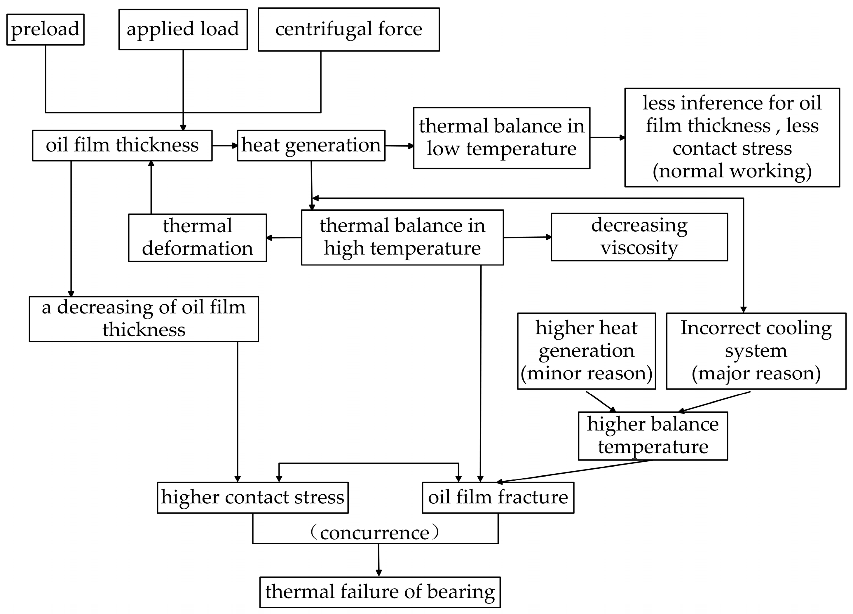
4.2.4. Analysis of Thermal Failure

The literature on the thermal analysis of a spindle-bearings system mainly focus on developing a model to estimate the temperature distribution of a spindle-bearing system and the investigation of rolling bearing failure due to excessive heat generation inside the bearing. Due to the multiplicity of parameters involved, a well-ordered block diagram is developed for analyzing the thermal failure of bearings.
As seen, Figure 20 depicts the block diagram constructed to investigate the thermal failure of the bearing. The entire process of the thermal failure of the bearing can be simply divided into six stages, namely frictional heat generation, thermal deformation, decreasing of oil film thickness, thermally-induced preload, oil film fracture, and thermal failure. Frictional heat generation can be calculated by considering key parameters such as preload, applied load, centrifugal force, and oil film thickness. If heat generation and heat dissipation achieve a steady state in a low temperature, so that the oil film thickness is invariable, the bearing is working normally. If the cooling system is incorrect, heat generation and heat dissipation achieve a steady state at a higher temperature, thermal deformation occurs, the oil viscosity and dimensions change, and the oil film thickness decreases. This will lead to higher contact stress or oil film fracture.

5. Conclusions

In this paper, a thermo-mechanical coupling model, a heat transfer model, and a temperature prediction model to analyze the thermal characteristics of the spindle-bearing system are presented. The comparative analysis of the experimental results and the theoretical results is discussed, and the following conclusions are obtained:
(1)
The thermo-mechanical coupling model, the heat transfer model, and the numerical calculation of the temperature prediction model can be used to analyze the transient and steady state thermal characteristics of the spindle-bearing system owing to the lumped assumption of the spindle and the finite number of temperature nodes of the entire system. The main factors of models such as applied force, preload, lubricating state, surface morphology, and rotational speed are numerically analyzed.
(2)
A heat transfer model can be used to estimate critical parameters such as the thermal contact resistance between the rolling element and the raceway, the convective heat transfer coefficient of the cooling system, and the grease. The accuracy of the temperature distribution calculation depends on the selection of the boundary conditions and the initial temperature.
(3)
Various experimental schemes are designed and a number of experimental real-time measuring are conducted for comparative analysis. Not only are the effectiveness, accuracy, and practicability of the mathematical models verified, but also a comprehensive understanding about the thermal characteristic of the spindle system at the transient and steady state can be obtained. These experiments can make the spindle avoid the appearance of the instantaneous temperature peak and the unnecessary thermal failure in actual conditions.
(4)
Analysis of the spindle rotational speed, the preload of the spindle bearing, the grease temperature, and the cooling system are carried out. The significant effect of the high rotational speeds, preload oil viscosity, and heat transfer coefficients on the temperature or thermal failure of the bearing has been revealed, and schemes to improve the R&D of the spindle-bearing system are provided.

Author Contributions

Li Wu proposed the mathematical models, designed and performed experiments, analyzed the data, and wrote the initial manuscript. Qingchang Tan revised the initial manuscript. Both authors have read and approved the final manuscript.

Conflicts of Interest

The authors declare no conflict of interest.

Nomenclature

Adistance between raceway groove curvature centers
fr/D
Bfi + fo − 1, total curvature
dmdiameter of pitch circle
rraceway groove curvature radius
Dball diameter
asemi-major axis of the contact area
bsemi-minor axis of the contact area
α0free contact angle
αmounted contact angle
Fppreload
EYoung’s modulus
ξPoisson’s ratio
δdisplacement of the bearing
θangular displacement of the bearing
Znumber of balls per bearing
ωrotational speed
σnormal contact stress
F(ρ)curvature difference
Σ(ρ)curvature sum
κeccentricity
βball pitch angle
β′ball yaw angle
Mgy′gyroscopic movement in y′ direction
Mgz′gyroscopic movement in z′ direction
Fccentrifugal force
Faaxial force
Ri(o)the radius of the locus of the raceway groove curvature center
ψazimuth angle of the rolling element
τfrictional shear stress
U ¯ speed parameter
Q ¯ Z load parameter
Gmaterial parameter
Qball-raceway normal load
Ffrictional force
Fvviscous friction force
Hheat generation rate

Appendix A. Surface Friction Shear Stress between Rolling Element and Raceway Groove

Hamrock and Dowson [20] proposed the following calculation formula of dimensionless oil film thickness [22]:
H 0 = 2.69 U ¯ 0.67 G 0.53 Q ¯ z 0.067 ( 1 0.61 e 0.73 κ ) ,
where G = λ E , U ¯ = η 0 U E R x , Q ¯ z = Q E R x 2 , E = E 1 ξ 2 .
Center oil film thickness can be expressed as
h 0 = H 0 R x .
By Boussinesq analysis, deformation displacements δ(x,y) caused by distributed stress σ(x,y) of elasticity surfaces is defined as
δ ( x , y ) = ( 1 ξ 1 2 π E 1 + 1 ξ 2 2 π E 2 ) Ω σ ( x , y ) ( x x ) 2 + ( y y ) 2 d x d y ,
where x′ and y′ are the additional coordinates corresponding to the x and y coordinates, respectively, and Ω is the solution domain.
Point-contact oil film thickness in elastohydrodynamic lubrication can be expressed as
h ( x , y ) = h 0 + x 2 2 R x + y 2 2 R y + δ ( x , y ) ,
where h0 is the oil film thickness of the contact center, and Rx and Ry are the equivalent curvature radii along the x, y direction.
To describe the contact of real surfaces, Greenwood and Williamson developed one of the first models that specifically accounted for the random nature of interfacial phenomena [32]. The ratio of contact to apparent area Ac/A0 is
A c A 0 = π R S s D S U M F 1 ( d S s ) ,
where R is the assumed constant radius of the spherical summits, Ss is the standard deviation of the summit height distribution, DSUM is the area density of summits, and d is the distance between the summit height and the surface mean plane. F1(t) is the integral
F 1 ( t ) = t ( x t ) ϕ ( x ) d x .
Other variables can be expressed as [28]:
R s = 3 8 ( π m 4 ) 1 2     S s = [ ( 1 0.8968 ( m 0 m 4 / m 2 2 ) ) m 0 ] 1 2 D S U M = m 4 6 π m 2 3     d S s = h m 0 1 2 4 ( π m 0 m 4 / m 2 2 ) 1 2 ( 1 0.8968 ( m 0 m 4 / m 2 2 ) ) 1 2 ,
where m0, m2, and m4 are known as the zeroth, second, and fourth spectral moments of a profile, respectively. They are equivalent to the mean square height, slope, and second derivative of a profile in an arbitrary direction.

Appendix B. Heat Transfer System of the Temperature Nodes

Table B1. Heat transfer system of the temperature nodes (C represents thermal conduction, V represents thermal convection, F represents heat generation).
NodeA123456789101112131415161718B
1--C--------CC-------
2-C-C-----V---CC-----
3--C-C----C----------
4---C-C---V----------
5----C-C--C----------
6-----C-C-V-----CC---
7------C-V--------CC-
8-------V---------VV-
9--VCVCV------VVVV---
10-V---------VV-------
11CC--------V--C------
12-C------------C----C
13C-C------V-C--------
14--C------V--C------C
15C-----C--V-------C--
16------C--V--------CC
17C------CV------C----
18-------CV-------C--C

References

  1. Tu, J.F.; Stein, J.L. On-line preload monitoring for anti-friction spindle bearings of high-speed machine tools. J. Dyn. Syst. Meas. Control Trans. ASME 1995, 117, 43–53. [Google Scholar] [CrossRef]
  2. Katter, J.G.; Tu, J.F. Bearing condition monitoring for preventive maintenance in a production environment. Tribol. Trans. 1996, 39, 936–942. [Google Scholar] [CrossRef]
  3. Choi, J.K.; Lee, D.G. Thermal characteristics of the spindle bearing system with a gear located on the bearing span. Int. J. Mach. Tools Manuf. 1998, 38, 1017–1030. [Google Scholar] [CrossRef]
  4. Lin, C.; Tu, J.F.; Kamman, J. An integrated thermo-mechanical-dynamic model to characterize motorized machine tool spindles during very high speed rotation. Int. J. Mach. Tools Manuf. 2003, 43, 1035–1050. [Google Scholar] [CrossRef]
  5. Nosonovsky, M. Entropy in Tribology: In the Search for Applications. Entropy 2010, 12, 1345–1390. [Google Scholar] [CrossRef]
  6. Lin, S.-K. Diversity and Entropy. Entropy 1999, 1, 1–3. [Google Scholar] [CrossRef]
  7. Min, X.; Shuyun, J.; Ying, C. An improved thermal model for machine tool bearings. Int. J. Mach. Tools Manuf. 2007, 47, 53–62. [Google Scholar] [CrossRef]
  8. Takabi, J.; Khonsari, M.M. Experimental testing and thermal analysis of ball bearings. Tribol. Int. 2013, 60, 93–103. [Google Scholar] [CrossRef]
  9. Bryant, M.D.; Khonsari, M.M. Application of Degradation-Entropy Generation Theorem to Dry Sliding Friction and Wear. In Proceedings of the STLE/ASME 2008 International Joint Tribology Conference, London, UK, 20–22 October 2008.
  10. Bryant, M.D. Entropy and dissipative processes of friction and wear. FME Trans. 2009, 37, 55–60. [Google Scholar]
  11. Amiri, M.; Khonsari, M.M.; Brahmeshwarkar, S. An Application of Dimensional Analysis to Entropy-Wear Relationship. J. Tribol. 2012, 134, 308–309. [Google Scholar] [CrossRef]
  12. Aghdam, A.B.; Khonsari, M.M. On the correlation between wear and entropy in dry sliding contact. Wear 2011, 270, 781–790. [Google Scholar] [CrossRef]
  13. Kagan, E. Turing Systems, Entropy, and Kinetic Models for Self-Healing Surfaces. Entropy 2010, 12, 554–569. [Google Scholar] [CrossRef]
  14. Aziz, A. Entropy Generation in Pressure Gradient Assisted Couette Flow with Different Thermal Boundary Conditions. Entropy 2006, 8, 50–62. [Google Scholar] [CrossRef]
  15. Prokopenko, M.; Gershenson, C. Entropy Methods in Guided Self-Organisation. Entropy 2014, 16, 5232–5241. [Google Scholar] [CrossRef]
  16. Bossmanns, B.; Tu, J.F. A thermal model for high speed motorized spindles. Int. J. Mach. Tools Manuf. 1999, 39, 1345–1366. [Google Scholar] [CrossRef]
  17. Holkup, T.; Cao, H.; Kolář, P.; Altintas, Y.; Zelený, J. Thermo-mechanical model of spindles. CIRP Ann. Manuf. Technol. 2010, 59, 365–368. [Google Scholar] [CrossRef]
  18. Mizuta, K.; Inoue, T.; Takahashi, Y.; Huang, S.; Ueda, K.; Omokawa, H. Heat transfer characteristics between inner and outer rings of an angular ball bearing. Heat Transf. Asian Res. 2003, 32, 42–57. [Google Scholar] [CrossRef]
  19. Chien, C.H.; Jang, J.Y. 3-D numerical and experimental analysis of a built-in motorized high-speed spindle with helical water cooling channel. Appl. Ther. Eng. 2008, 28, 2327–2336. [Google Scholar] [CrossRef]
  20. Harris, T.A.; Kotzalas, M.N. Advanced Concepts of Bearing Technology: Rolling Bearing Analysis, 5th ed.; CRC Press: Boca Raton, FL, USA, 2006. [Google Scholar]
  21. Masjedi, M.; Khonsari, M.M. Theoretical and experimental investigation of traction coefficient in line-contact EHL of rough surface. Tribol. Int. 2014, 70, 179–189. [Google Scholar] [CrossRef]
  22. Takabi, J.; Khonsari, M.M. On the dynamic performance of roller bearings operating under low rotational speeds with consideration of surface roughness. Tribol. Int. 2015, 86, 62–71. [Google Scholar] [CrossRef]
  23. Hamrock, B.J.; Dowson, D. Ball Bearing Lubrication: The Elastohydrodynamics of Elliptical Contact; Wiley: New York, NY, USA, 1981. [Google Scholar]
  24. Dowson, D. Elastohydrodynamic and micro-elastohydrodynamic lubrication. Wear 1995, 190, 125–138. [Google Scholar] [CrossRef]
  25. Nakajima, K. Thermal contact resistance between balls and rings of a bearing under axial, radial, and combined loads. J. Thermophys. Heat Transfer. 1995, 9, 88–95. [Google Scholar] [CrossRef]
  26. Hu, T.; Yin, G.; Deng, C. Approach to Study Bearing Thermal Preload Based on the Thermo-Mechanical Information Interaction Net. Int. J. Control Autom. 2014, 7, 299–312. [Google Scholar] [CrossRef]
  27. Tu, J.F.; Stein, J.L. Active thermal preload regulation for machine tool spindles with rolling element bearings. J. Manuf. Sci. Eng. Trans. ASME 1996, 118, 499–505. [Google Scholar] [CrossRef]
  28. Tu, J.F. Thermoelastic instability monitoring for preventing spindle bearing seizure. Tribol. Trans. 1995, 38, 11–18. [Google Scholar] [CrossRef]
  29. Stein, J.L.; Tu, J.F. A state-space model for monitoring thermally induced preload in anti-friction spindle bearings of high-speed machine tools. J. Dyn. Syst. Meas. Control Trans. ASME 1994, 116, 372–386. [Google Scholar] [CrossRef]
  30. Du, Z.C.; Yao, S.Y.; Yang, J.G. Thermal Behavior Analysis and Thermal Error Compensation for Motorized Spindle of Machine Tools. Int. J. Mach. Tools Manuf. 2015, 7, 1571–1581. [Google Scholar] [CrossRef]
  31. Kim, S.-M.; Lee, K.-J.; Lee, S.-K. Effect of bearing support structure on the high-speed spindle bearing compliance. Int. J. Mach. Tools Manuf. 2002, 42, 365–373. [Google Scholar] [CrossRef]
  32. Kim, S.-M.; Lee, K.-J. Prediction of thermo-elastic behavior in a spindle–bearing system considering bearing surroundings. Int. J. Mach. Tools Manuf. 2001, 41, 809–831. [Google Scholar] [CrossRef]
  33. Ma, L.; Zhao, X.; Sun, H.; Wu, Q.; Liu, W. Experimental Study of Single Phase Flow in a Closed-Loop Cooling System with Integrated Mini-Channel Heat Sink. Entropy 2016, 18, 128–141. [Google Scholar] [CrossRef]
  34. Pang, L.; Wang, M. Optimal Thermal Design of a Stacked Mini-Channel Heat Sink Cooled by a Low Flow Rate Coolant. Entropy 2013, 15, 4716–4731. [Google Scholar] [CrossRef]
Figure 1. The spindle-bearing system.
Entropy 18 00271 g001
Figure 2. Position of the ball center and raceway groove curvature centers.
Entropy 18 00271 g002
Figure 3. Ball model with forces and moments.
Entropy 18 00271 g003
Figure 4. Simplified temperature node system selected for spindle system analysis.
Entropy 18 00271 g004
Figure 5. Temperature and thermal resistance model along the radial direction of the spindle system.
Entropy 18 00271 g005
Figure 6. Two-dimensional temperature node system.
Entropy 18 00271 g006
Figure 7. Rolling element lubricant raceway ring temperature node system.
Entropy 18 00271 g007
Figure 8. Measurement system and temperature distribution of spindle.
Entropy 18 00271 g008
Figure 9. Comparison of the predicted housing temperature to the measured value by sensors for the test conditions of 3000 rpm and 1750 N preload.
Entropy 18 00271 g009
Figure 10. Comparison of temperature during step testing from 0 to 4500 rpm.
Entropy 18 00271 g010
Figure 11. Friction heat generation rate vs. rotational speed (Pa = 350 N).
Entropy 18 00271 g011
Figure 12. Friction heat generation rate vs. rotational speed (Pa = 1750 N).
Entropy 18 00271 g012
Figure 13. Measured radial thermal deformation of the spindle.
Entropy 18 00271 g013
Figure 14. Oil film thickness of the grease in contact center.
Entropy 18 00271 g014
Figure 15. Measured temperatures during step test from 0 to 4500 rpm.
Entropy 18 00271 g015
Figure 16. Cooling oil heat transfer coefficient.
Entropy 18 00271 g016
Figure 17. Temperatures along the radial direction of the spindle system in thermal balance state.
Entropy 18 00271 g017
Figure 18. Temperatures along the radial direction of the spindle system after optimization.
Entropy 18 00271 g018
Figure 19. Thermal deformation vs. rotational speed.
Entropy 18 00271 g019
Figure 20. Cause-and-effect model of the bearing thermal failure.
Entropy 18 00271 g020

