A Novel Codeword Selection Scheme for MIMO-MAC Lower-Bound Maximization


1
Department of Electrical Engineering, University of Engineering & Technology, Peshawar P.O. Box 814, Pakistan
2
Integrated Management Coastal Research Institute, Universitat Politecnica de Valencia, Gandia, 46730 Valencia, Spain
3
Institute of Telecommunications and Multimedia Applications (iTEAM), Universitat Politècnica de València, Camino Vera n/n, 46022 Valencia, Spain
*
Author to whom correspondence should be addressed.
Entropy 2018, 20(8), 546; https://0-doi-org.brum.beds.ac.uk/10.3390/e20080546
Submission received: 25 June 2018
/
Revised: 20 July 2018
/
Accepted: 20 July 2018
/
Published: 24 July 2018
(This article belongs to the Section Complexity)
Abstract
:Aiming at the limitations of the existing Limited Feedback Interference Alignment algorithms, this paper proposes a direct codeword selection scheme that maximizes the lower-bound of the user rate and reduces the sum rate loss by integrating the Bit Allocation algorithm. The target signal is decoded using the maximum signal to interference plus noise ratio (MAX-SINR) algorithm. Moreover, low complexity and global searching mechanisms are deployed to select the optimized codewords from the generated sets of codewords that approach the ideal precoder. Simulation results show that the proposed algorithm effectively improves the rate lower-bound of the system user as compared with the existing state-of-the-art algorithms.
1. Introduction
Multiple-input multiple-output (MIMO) is a technology which can make great enhancements in terms of the overall throughput of the network. How to eliminate the interference of cell edge users in the multi-cell multi-user MIMO downlink has been a research hotspot in recent years. Interference Alignment (IA) can solve the interference problem and increase the achievable rates [1,2]. However, this usually needs to know the local or even global Channel State Information (CSI), and it generally uses the feedback from the receiver. The limited feedback of IA shares the same codebook between the transmitter and receiver, and the receiver quantizes the channel matrix or precoding according to the obtained CSI and sends feedback for the location index of the quantization codeword [3,4]. Because the quantized channel matrix has a larger dimension than the quantized precoding matrix, the quantized precoding scheme has been widely studied [5,6,7,8,9,10,11,12,13,14,15,16,17,18,19,20]. This paper proposes a MIMO Multiple Access Channel (MIMO-MAC) limited feedback IA algorithm that maximizes the rate lower-bound of the system user. It is based on three main steps of operations. First, according to the different channel qualities of each user, bit allocation is performed. After this, selecting the codewords closer to the ideal precoding in the Grassmann codebook space generates an optional set of codewords and adopts the maximum signal to interference plus noise ratio (MAX-SINR) algorithm for decoding. Finally, the codeword combination that can make the user’s rate lower-bound is searched in the set as the optimal quantization precoding. In the proposed algorithm, low-complexity and sub-optimal global search are implemented simultaneously. Simulation results show that compared with other state-of-the-art algorithms, the proposed algorithm effectively improves the user’s sum rate and the lower-bound for the user’s sum rate in the system.
The rest of the paper is organized as follows. Section 2 presents the related work of the paper. Section 3 discusses the system model and analytical derivations. Section 4 explains the proposed algorithm. Section 5 describes the rate loss analysis and bit allocation algorithm of the proposed research work. Section 6 provides the pseudocode and computational complexity of the proposed algorithm. Simulation results and discussions are provided in Section 7 while Section 8 concludes the paper.
2. Related Work
Interference Alignment (IA) can effectively solve the interference problem in the interference channel and increase the achievable sum rate of the channel [21,22]. However, it requires global CSI to design the interference suppression matrix, usually using the feedback of the receiver to inform the CSI required by the transmitter [23,24]. In order to save the bandwidth of feedback, the finite feedback of IA shares the same codebook between the transmitter and receiver. The receiver determines the optimal precoding from the global CSI and finds the optimal codeword from the codebook. Then it finds the location index Limited feedback [25,26]. Because the channel matrix dimension is larger than the precoding matrix, the feedback precoding algorithm is better, and the limited feedback of IA achieves greater performance improvement with less feedback and has been widely studied [5,6,7,8,9,10,11,12,13,14,15,16,17,18,19,20].
In the scheme of quantizing channels, the authors in [27] showed that in the -path frequency selective channel, the degree of freedom (DoF) of can still be obtained when the receiver has only feedback bits. In [28], the authors performed Quadratic Reciprocity (QR) decomposition on the joint interference channel to obtain an equivalent unitary matrix and quantized it in the Grassmann codebook, which reduced the performance loss. In the quantized precoding scheme, for the case of a MIMO uplink of two-cells and users per cell, the authors in [29] align the inter-cell interference (ICI) through inter-base station (BS) interaction CSI joint design precoding. The interference suppression matrix is obtained with the interference in the cell, and finally, the precoding is directly quantized. In [30] and in the literature [29], the ICI and the intra-cell interference cannot be eliminated. In both papers, they first quantified the precoding and redesigned the interference suppression matrix to eliminate the intra-cell interference. In [31], the authors address the problem that ICI cannot be eliminated in [30] and minimize ICI through a direct codeword solution. The authors in [32] extended [30] to several degrees of freedom and improved its performance. The authors in [33] improved the ICI alignment in the direction that is most conducive to receiving rather than that of the traditional randomization direction. On the basis of [33], authors in [34] minimize ICI by jointly selecting quantized codewords, but with high complexity. The authors in [35] prove that using a Grassmann codebook can further improve the system performance. The authors in [36,37] analyze the impact of different decoding algorithms and different system parameters on system performance.
It can be seen that the traditionally limited feedback schemes are based on the criterion of minimum chordal distance [29,30,32] or alignment [31]. It does not consider the overall performance, nor does it consider that the interference suppression matrix may make interference amplification problems. In addition, the joint quantification in [34] is better than the independent quantification performance in [33], but the quality of the signal transmission is not considered; however, the authors in [36,37] only theoretically analyze the performance of limited feedback. Therefore, for the MIMO-MAC case, the codeword can be selected from the perspective of optimizing the overall system performance.
For this reason, this paper proposes a MIMO-MAC limited feedback IA algorithm that maximizes the rate lower-bound of the system user. First, according to the different channel qualities of each user, bit allocation is performed. Secondly, selecting the codewords closer to the ideal precoding in the Grassmann codebook space constitutes an optional set of codewords and adopts the maximum signal to interference plus noise ratio (MAX-SINR) algorithm for decoding. Finally, the codeword combination that can make the user’s maximum rate lower-bound is searched in the set as the optimal quantization precoding. At this time, low-complexity and sub-optimal global search are implemented at the same time. The simulation shows that compared with other algorithms, the proposed algorithm effectively improves the lower-bound of the user’s achievable rate.
3. System Model
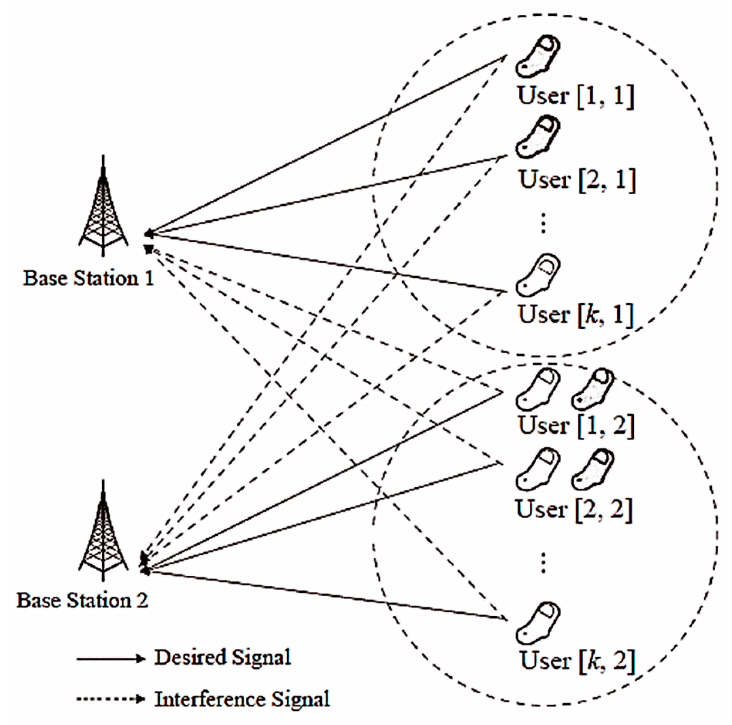
This paper considers the MIMO-MAC model consisting of two-cells and users per cell. The number of transmitting antennas is and the number of receiving antennas is . The system model is shown in Figure 1.
In order to maximize the total DoF, the dimension of the signal space provided by each user should be equal, that is, each user has the same DoF and is assumed to be . Assume that the channel between each user-BS pair is flat fading and the channel coefficients are independent and identically distributed (i.i.d). The received signal of the th BS for a specific time-frequency can be expressed as:
where is the reference distance, and represent the propagation distances from user and the d to th BS, respectively. is the path loss exponent. and represent the channel matrix from the user and to the th BS, respectively, which follows the complex Gaussian distribution with zero mean and unit variance. and are the precoding matrices for users and corresponding to th and th BSs, respectively, which satisfy and . and are the uplink data vector signals for users and which satisfy the power constraints and , respectively. and represent the transmit power for the users and , respectively. is the additive white Gaussian noise with zero mean and a variance of , that is, .
The BS uses the receiver filter for processing. At this time, the received signal for the user is:
4. New Limited Feedback Interference Alignment Algorithm
4.1. Precoding Matrix and Codeword Selection Scheme
From the perspective of IA, the aligned ICI channels, from users in the th cell to the th BS, span the intersection subspace , which can be expressed as:
where and represent the channel matrix for the user to the th BS, respectively. The pre-encoded and aligned interference term that satisfies Equation (3) can be obtained by Equation (4):
It can be known from [38] that when sending multiple data streams, Schmidt orthogonalization is performed on the pre-coded column vectors, which can further increase the user rate. Therefore, we consider using Schmidt orthogonalization to handle precoding, which can be expressed as:
where “orth” denotes Schmidt orthogonalization. According to the theory of matrix, we can know that:
where is the column generation space for , , and , and they span the same space. So, using as the precoding does not affect the IA constraint of Equation (3).
Under ideal CSI, precoding can be completely aligned to ICI according to Equations (4) and (5). Zero-Forcing (ZF) processing at the receiver can extract useful signals. With limited feedback, the achievable rate for the user can be expressed as:
where
In Equation (8), the first, second, and third terms represent the interference leakage caused by Inter-symbol Interference (ISI), Inter-user Interference (IUI), and Inter-cell Interference (ICI), respectively. The and represent the th column of the interference suppression matrix and the quantization precoding matrix, respectively. and denote the signal power for the user and the user , respectively, when the signal propagates to the th BS.
According to the minimum chordal distance criterion, which guarantees that the angle between the precoding and the ideal precoding is the minimum, but after processing by the receiving filter matrix, the interference may be amplified, and, therefore, Equation (8) cannot be guaranteed to be the minimum [12]. In addition, the use of independent quantitative precoding will also cause some users to receive more severe interference. In summary, it can be seen that the limited feedback needs to consider two factors comprehensively. That is, smaller chordal distance and less interference can improve the overall performance. For this reason, this paper establishes a feasible region and finds the optimal codeword combination through a low complexity search within a small distance from the ideal precoding string.
The specific implementation is as follows. Calculate the chordal distance between the ideal precoding and all codewords in the codebook which can be expressed as:
where and. It is worth noting that each is a semi-unitary matrix, and is the number of bits fed back by the user . With limited feedback, the optimal region of the precoding matrix for user is:
where denotes finding g codewords with minimum distance from in codebook .
4.2. Decoding Algorithm Improvement
In the case of quantitative precoding determination, the ZF algorithm [32] is not optimal for decoding. Therefore, this paper considers the decoding of the MAX-SINR algorithm. For the qth data stream for the user , the SINR is expressed as:
where and matrices are calculated as follows:
Since and are Hermita matrices and are positive definite. According to the definition of the generalized feature space, the existence of the dimensional matrix makes the following conditions satisfied:
where the column vector of the matrix is the generalized eigenvector of the matrix . The main diagonal elements of the diagonal array are all non-negative real numbers and are arranged in descending order with and . For this, just take as the first column of . So, the unit vector maximizing the SINR is expressed as:
where represents the unit eigenvector corresponding to the maximum eigenvalue of matrix.
5. Rate Loss Analysis and Bit Allocation Algorithm
5.1. Rate Loss Analysis
In limited feedback, it can be known from [23] that the performance of decoding using Equation (16) will be better than that of [32], and the user’s rate loss will be less than the literature [32]. So, there is a condition:
where and indicate the interference leakage of the qth data stream of user when using the proposed algorithm and the literature [32], respectively. The average power of the interference leakage under limited feedback can be calculated as:
where . When the codebook is generated in a sphere-packing procedure, the upper bound on the maximum value of the quantization error is given as [38]:
where the constant is the coefficient of the ball volume in the Grassmannian manifold and [38]. Putting Equation (19) into (18), we have the upper-bound of the average power of the overall interference leakage as:
5.2. Bit Allocation Algorithm
When the total number of feedback bits in the system is and is fixed, the interference leakage can be reduced, and sum rate can be improved by minimizing the expected quantization error due to ICI through an adaptive bit allocation algorithm. Combined with Equation (20), the optimization problem can be described as follows:
where .
Strictly solving Equation (21) will be very complicated since it is a non-linear integer problem and requires very high computational complexity as the total number of feedback bits increases. Since the objective function is log-convex-optimized, we can use a convex optimization technique to obtain the closed-form solution of Equation (21). The Lagrangian function expression of Equation (21) is as follows:
From Equation (22), we find the first order optimality Karush-Kuhun-Tucker (KKT) conditions as:
By solving Equations (23) and (24), we get the suboptimal solution:
where and means to find the largest integer not greater than .
6. Algorithm Summary and Theoretical Performance Analysis
6.1. Algorithm Summary
Through the above analysis, the limited feedback IA algorithm (Algorithm 1) is summarized as follows:
| Algorithm 1 Limited Feedback IA |
| Step 1: Determine the bit allocation using Equations (25) according to the user’s channel quality. Step 2: Obtain the ideal precoding according to Equations (4) and (5), according to the ideal CSI. Step 3: Generate the precoding feasible region according to Equations (9) and (10), according to the ideal precoding obtained in Step 2. Step 4: Select one code word for each user in the feasible field and generate a user quantized precoding combination. Step 5: Perform decoding according to Equation (16), according to the obtained quantized precoding combination. Step 6: Calculate the channel capacity of all users and let the smallest element in the channel capacity set be . Step 7: Repeat steps 4 and 5 until a codeword combination that maximizes is found in the precoding feasible region, and the corresponding codeword combination is used as the optimal quantization precoding combination. Step 8: Feedback the location index of the best-quantized precoding in the codebook to the transmitter. |
6.2. User Rate Lower-Bound Analysis
In limited feedback, the overall performance can only be improved by only considering a small chordal distance and less interference. For this reason, this paper establishes a smaller feasible region around the ideal precoding and finds the optimal combination of codewords by simply searching. The idea of IA is to divide the interference and signal into independent subspaces. The design of the interference suppression matrix is considered from the perspective of balancing the interference between each other using a joint strategy [3]. In the MIMO-MAC model, from the perspective of space, if the ICI can be completely aligned, then only a simple ZF processing needs to be performed at the receiver. On the other hand, the ICI processing can also be analyzed to be better or poorer. This paper maximizes the lower limit of user rates, assuming that cell 1 is used. When the lower limit of the user 1 rate is increased, then it can be seen that the interference of cell 2 to cell 1 is reduced, and the user rate in cell 1 is improved. The quantitative precoding for the user in fixed cell 2 finds cell 1 by further searching the codeword. The reduced codewords for cell 2 further enhance the user’s rate in cell 2. Through such overlapping searches, the optimal codeword combination can be obtained in the feasible region. For this reason, such searches not only increase the lower limit of the system user rate but also improve the spectral efficiency (SE).
6.3. Complexity Analysis
According to the deduction, the user rate loss is:
The first inequality is determined by the increasing function and . The second inequality is because and are evenly distributed in space. and are also uniformly distributed in space and are obtained by Jensen inequality. Putting Equation (20) into Equation (26) we get:
From Equation (27), we can see that is linearly proportional to in order to guarantee the same DoF as the ideal CSI. Therefore, there is:
where is a scale factor. Because the DoF is defined as , in order to achieve the DoF, it is known from Equation (28). The number of feedback bits can be expressed as:
In order to obtain the optimal precoding matrix, [9,10,12] require the number of searches to be [11] requires , and [14] requires . In order to obtain the optimal precoding matrix, the proposed algorithm requires . It can be seen that the complexity of the proposed algorithm is higher than that of [9,10,12] but lower than [11,14].
6.4. Number of Required Antennas
For the 2-user MIMO-MAC channel, in each cell of 2 cells for the total DoF to be 4, the transmitter in [13] needs 3 antennas and the receiver needs at least 3 antennas. In [9,10,11,12,14], by aligning the ICIs together, only 2 transmitter antennas and 3 receiver antennas are required, and a DoF of 4 can be obtained. From Equation (4), we can determine that if we have a solution (4) and each user gets a DoF of , then there must be:
7. Simulation Results and Analysis
We deployed MATLAB for performing the analysis and experimentation. Consider the system configuration of . That is, two cells, users per cell, a MIMO-MAC model with a DoF of for each user, and the number of BS antennas is . The number of subscriber antennas is . All channels are flat Rayleigh fading, and their elements satisfy a cyclic symmetric complex Gaussian distribution with a zero mean and unit variance. The channel noise is an Additive White Gaussian Noise with a zero mean and unit variance. Finally, the proposed algorithm is compared with the algorithms of [9,12,14]. All the simulations take 10,000 channel averages.
7.1. Average Spectral Efficiency under Ideal CSI
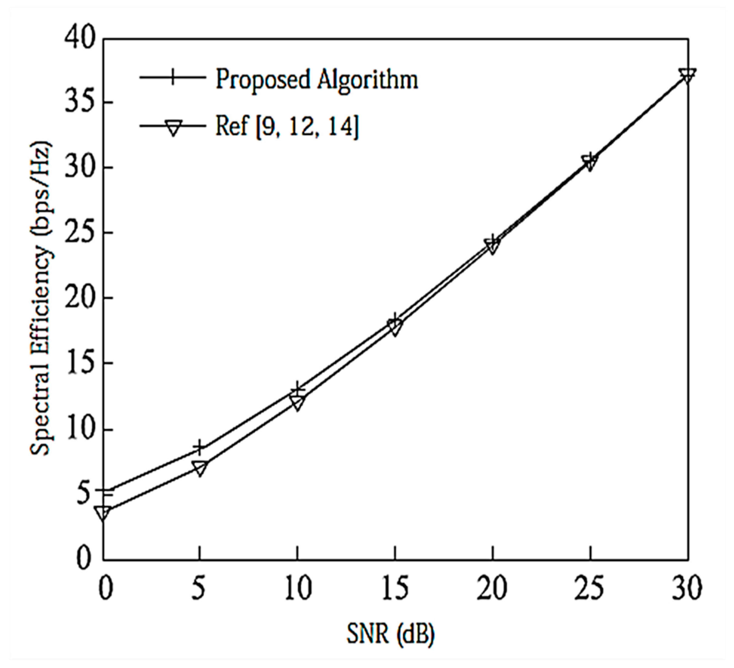
Figure 2 compares the SE of the proposed algorithm with other state-of-the-art algorithms. We assume that there is no power loss when the signal propagates to the BS. Under the configuration of , since there is no interference between data streams, the performance of [9,12,14] is the same and the MAX Signal-to-Interference plus Noise Ratio (MAX-SNR) is used in this paper. The proposed algorithm has better performance than the existing algorithms.
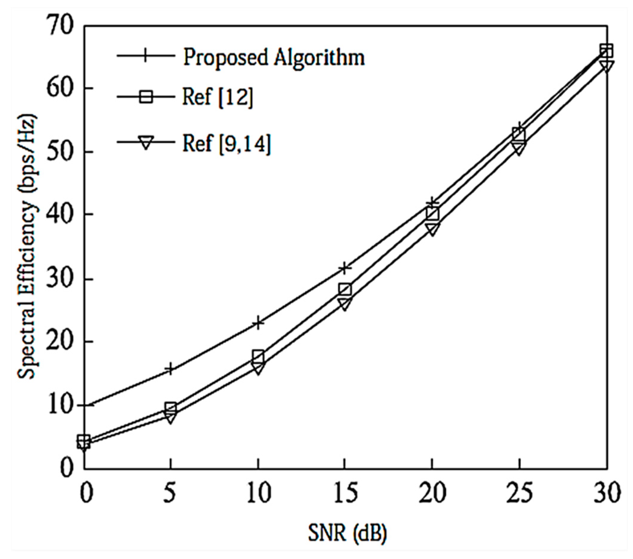
Under the configuration of , as shown in Figure 3, the DoF for each user is 2, and [12] considers the correlation between user data streams when designing the precoding matrix, and its performance is better than that of [9,14]. In this paper, the precoding matrix is designed to reduce the interference between data streams by using a Schmidt positive-cost reduction, and the decoding is performed using the MAX-SINR algorithm. Therefore, the proposed IA algorithm has better SE than [12].
7.2. Average Spectral Efficiency under Limited Feedback CSI
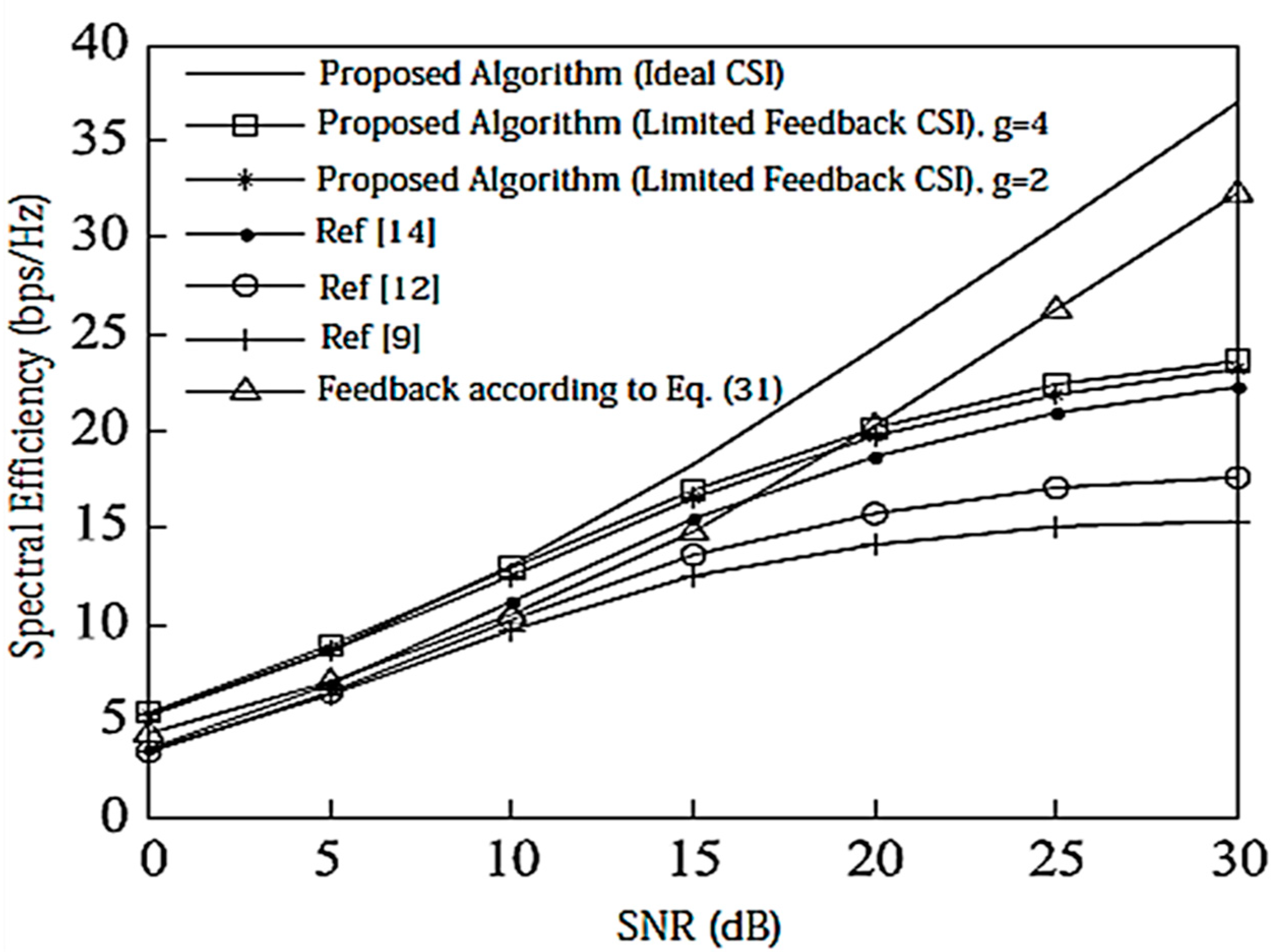
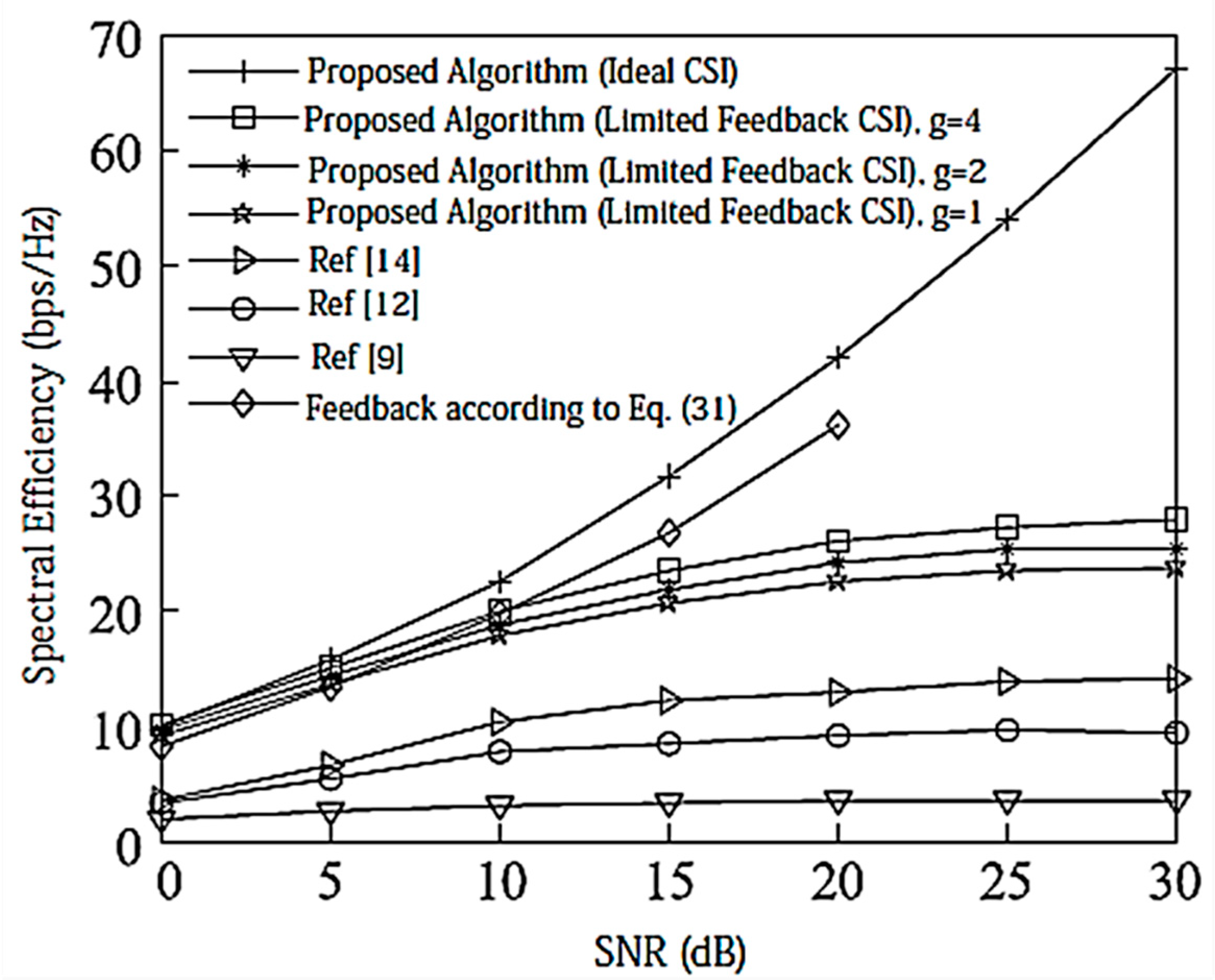
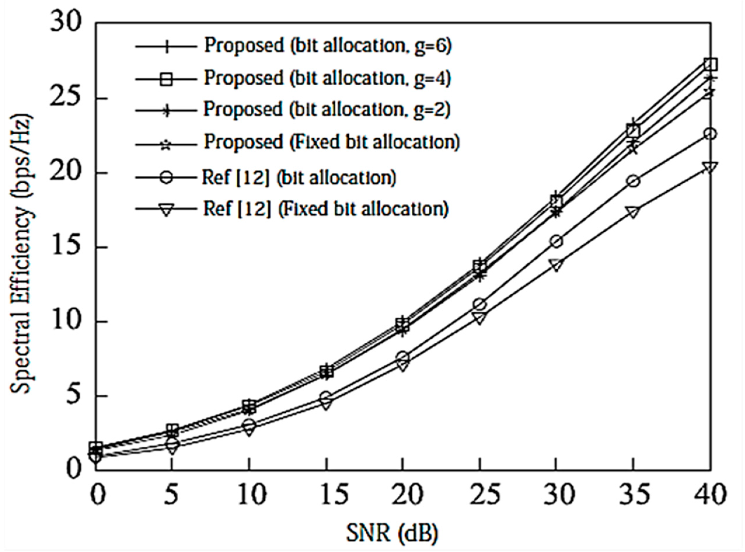
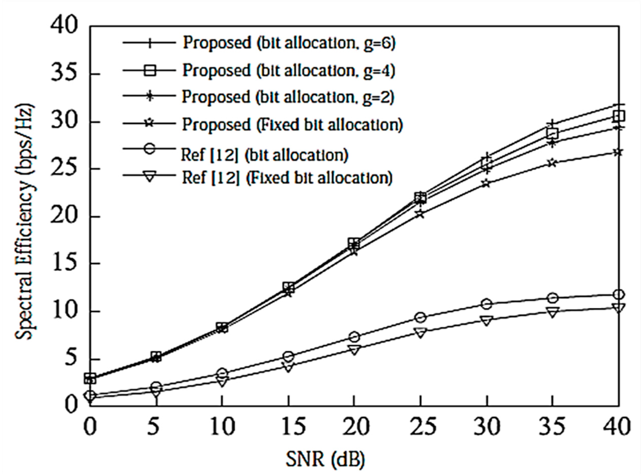
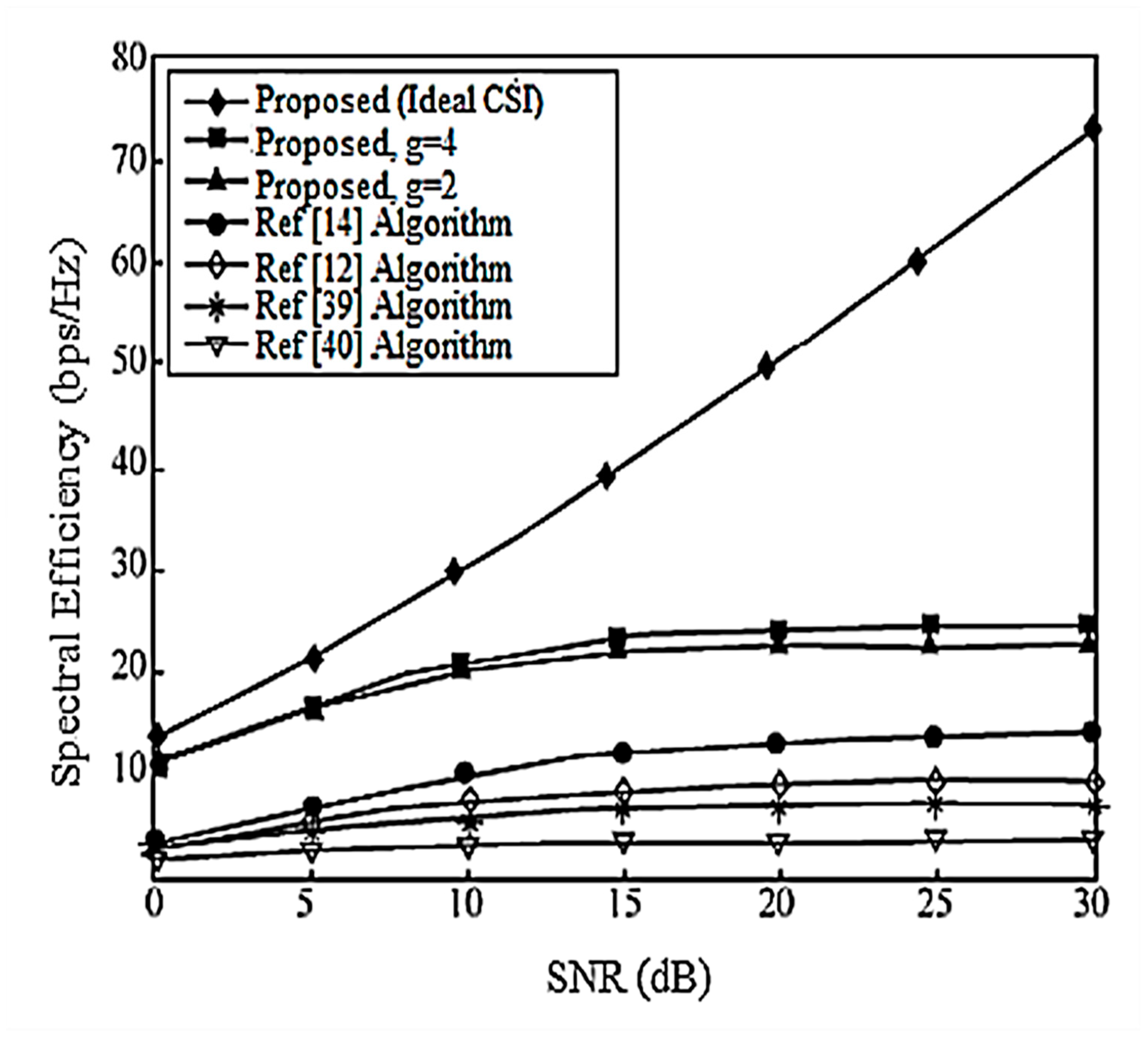
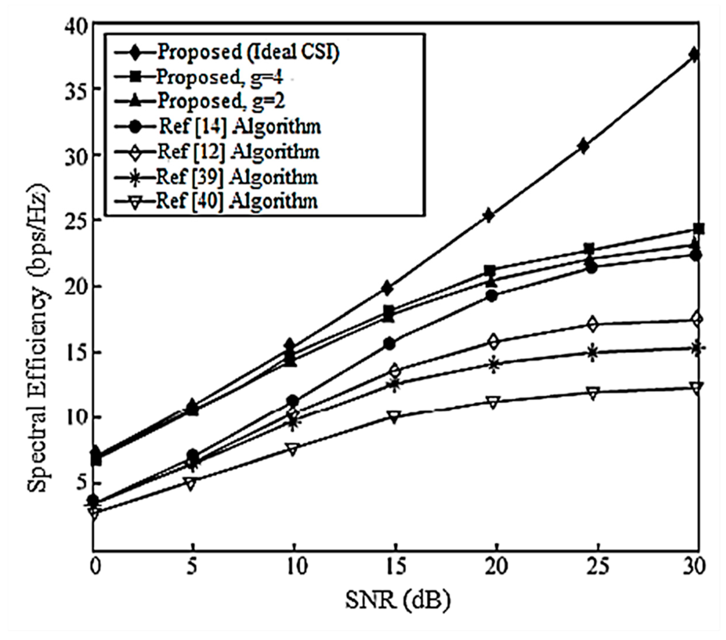
Assume here that there is no power loss when the signal propagates to the BS. When the system is configured as and , the algorithm passes through the receiver SINR, and searches for the optimal codeword in the codebook domain close to the ideal precoding, which can further improve the system performance. In the multi-DoF transmission, Schmidt orthogonalization is performed on precoding, which further weakens the interference between user data streams. From Figure 4 and Figure 5, it can be seen that [14] adopts a joint quantification strategy and its performance is better than [9,12], but the joint selection strategy of the proposed IA algorithm using the maximum SINR is relative to that of [14]. The joint strategy of the proposed IA algorithm to minimize the interference leakage is better than that of [9,12,14]. In addition, as can also be seen from the Figure 4 and Figure 5, according to Equation (31), the number of feedback bits can indeed guarantee the DoF of the system.
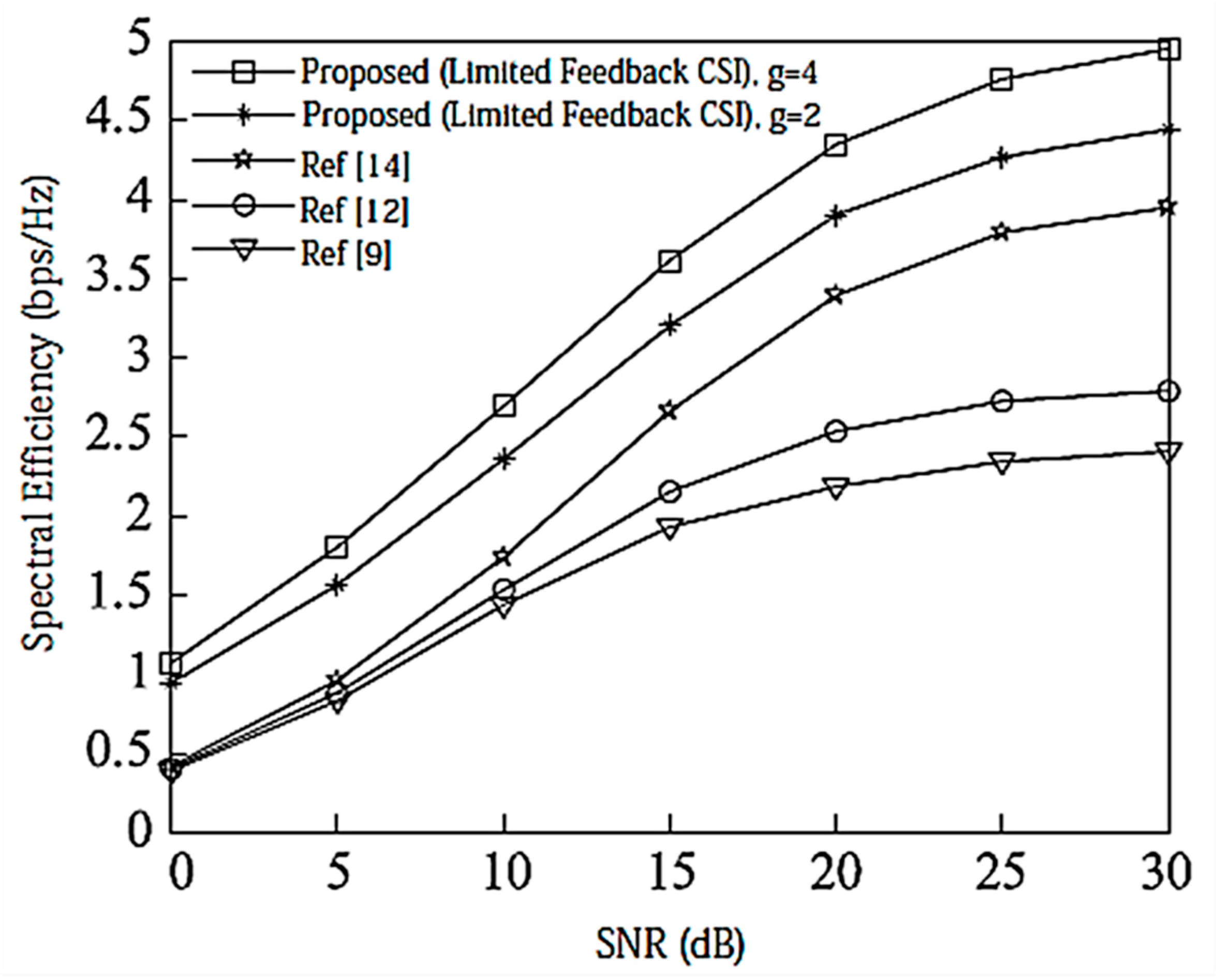
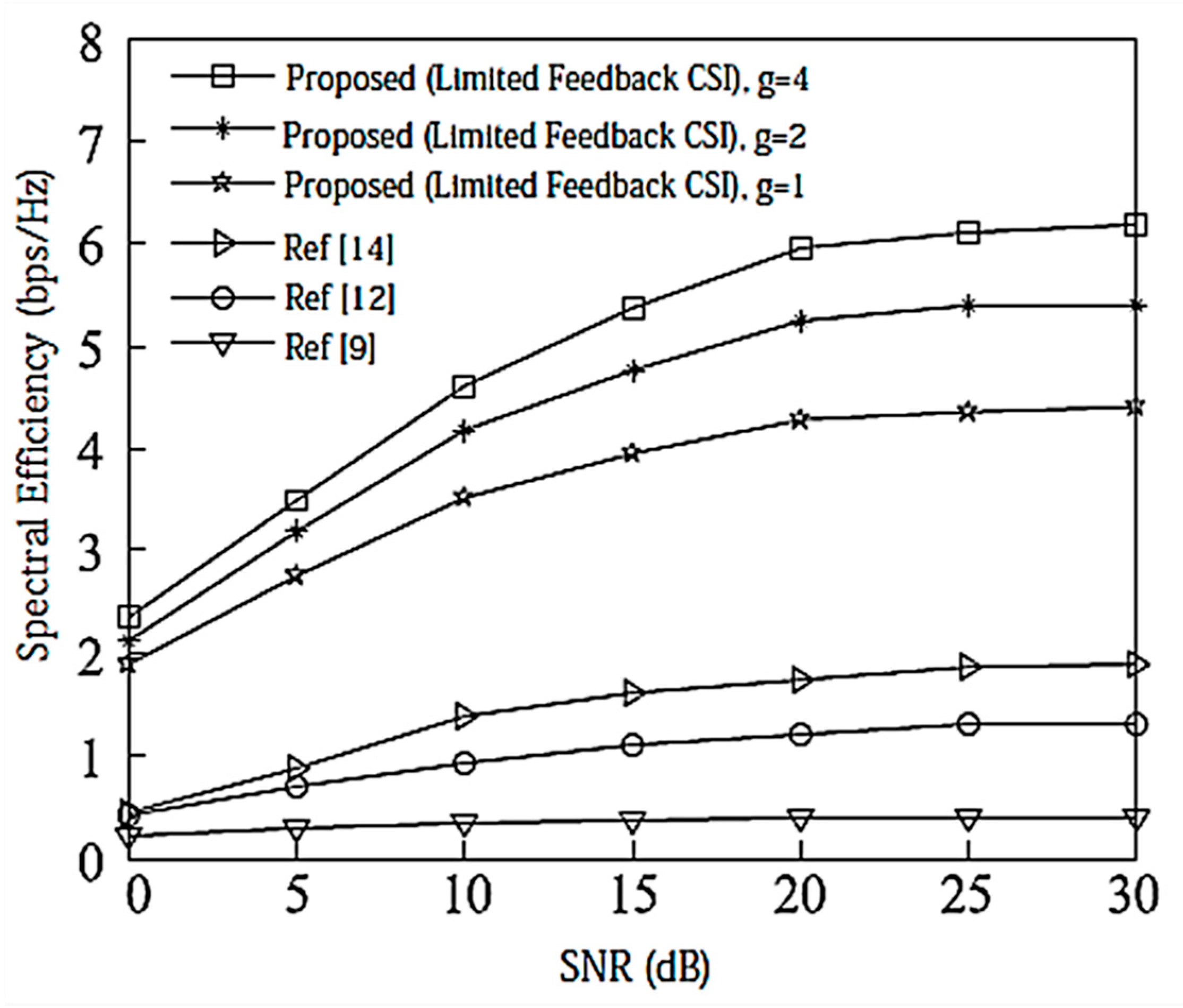
According to the analysis in Section 6, the proposed IA algorithm cannot only increase the sum rate of the system, but it also increases the lower limit of the system user rate. For this reason, Figure 6 and Figure 7 compare the lower limit of the system user rate when using different algorithms. From these two figures, it can be seen that the proposed algorithm effectively improves the overall system performance, and increasing the search range appropriately can further increase the lower limit bound of the system user rate.
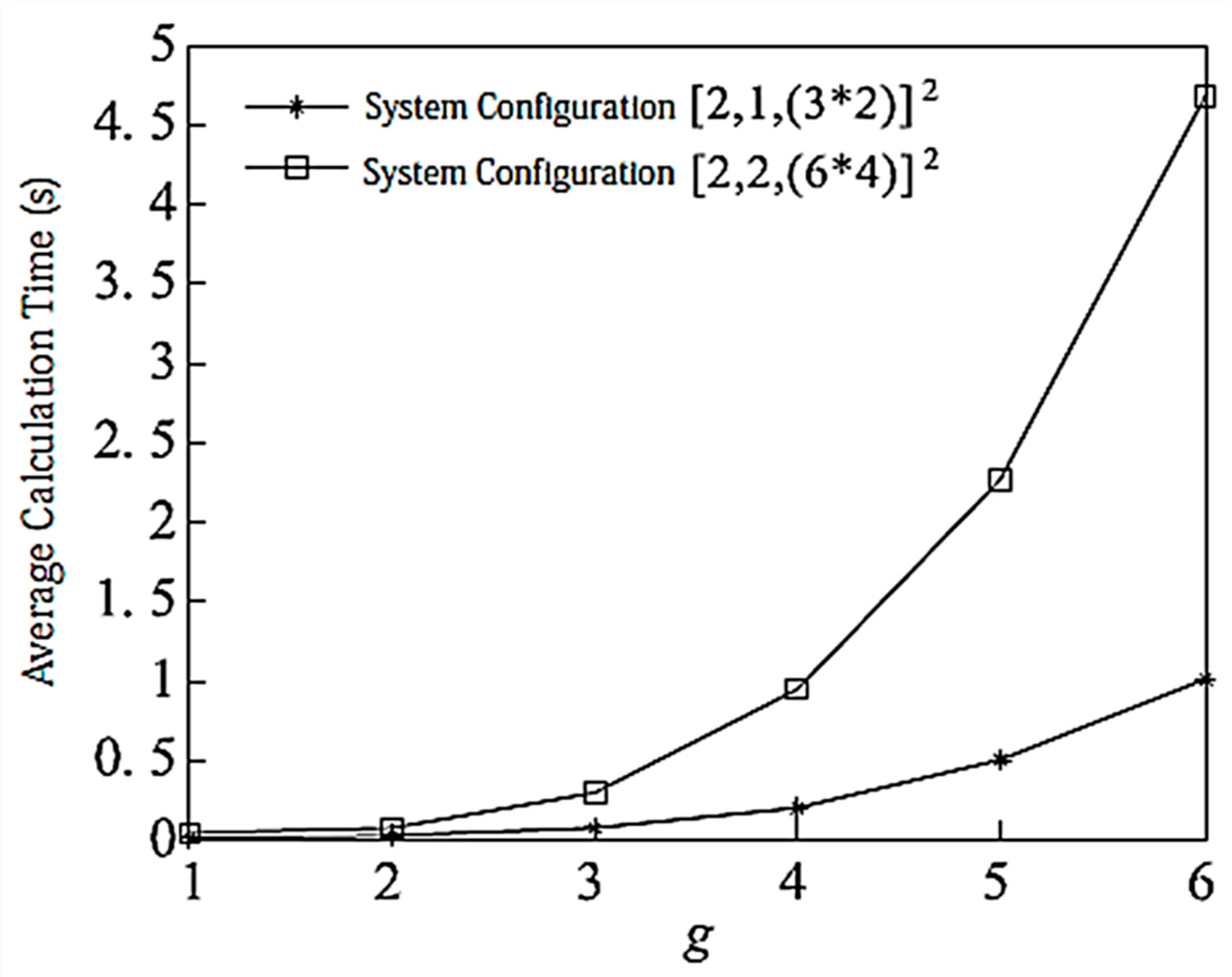
Figure 8 shows the complexity of the proposed algorithm when g is taken as a different value and when the system is configured as and . The simulation is based on 10,000 channel averages, the secondary channel averages, and each user bit = 8. It can be seen from the Figure that the configuration has greater computational complexity than .
7.3. Spectral Efficiency Analysis Considering Channel Attenuation with Limited Feedback CSI
Assume that the BS radius , , and all users fall within the distance from the target BS . The total number of feedback bits for all users is considered here . As can be seen from Figure 9 and Figure 10, the proposed algorithm uses bit allocation and searches for the optimal codeword in the codebook domain, which is close to the ideal precoding system performance. It can also be seen that when the system is configured as , the performance improvement is better than that of which is more obvious from the results.
7.4. Average Spectral Efficiency under Ideal CSI
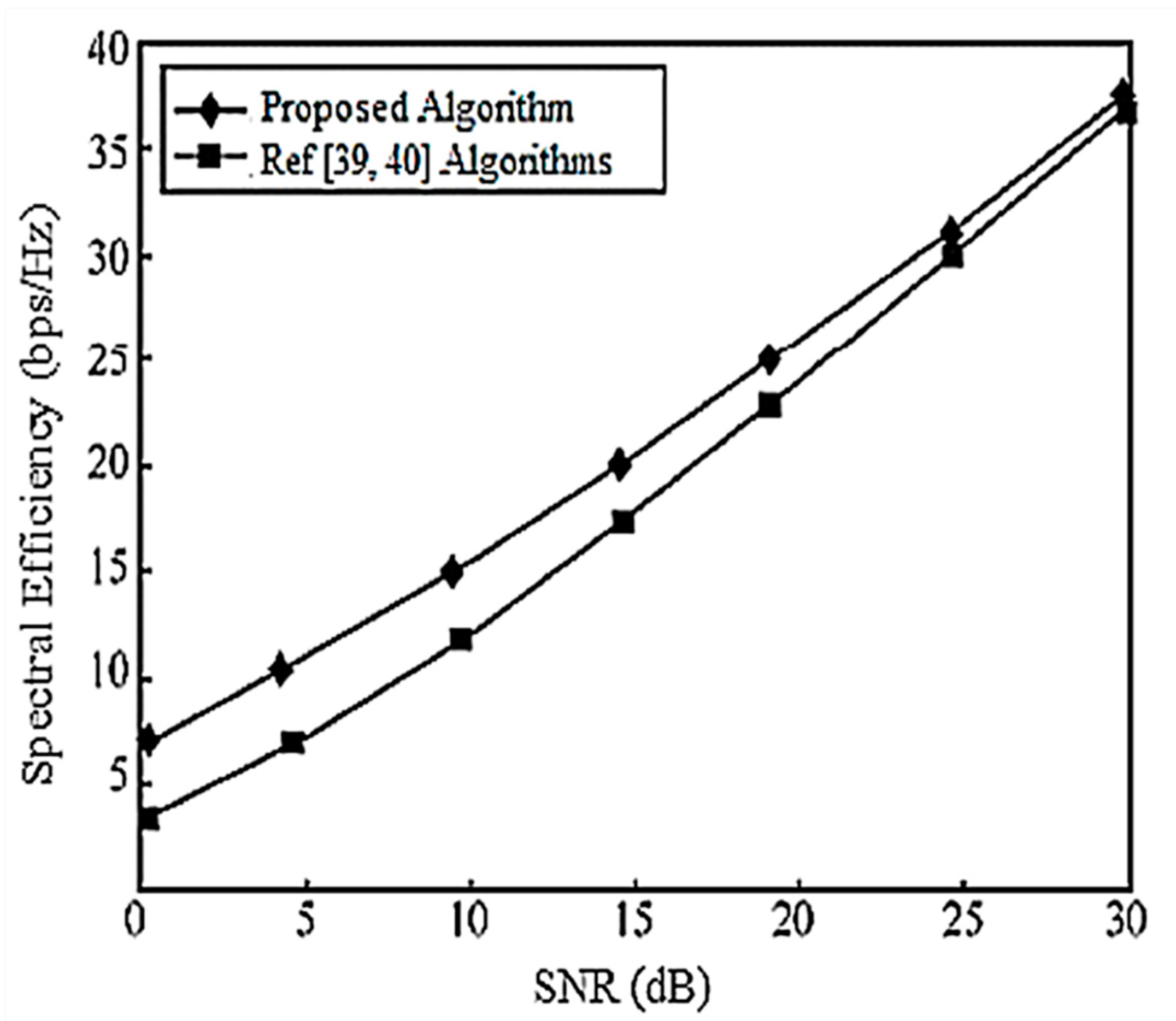
When the system is configured as and , the corresponding system SEs are shown in Figure 11 and Figure 12, respectively, and they are compared with [39,40] for performance evaluation. It is assumed that there is no power loss when the signal propagates to the BS. As can be seen in Figure 11, under the configuration of , each user has a DoF of 1 (i.e., a single data stream), and [39,40] have the same performance by completely, eliminating the interference algorithm, but the performance is the same. The scheme cannot guarantee the compression of the interference rotation to the optimal receiving direction, and the algorithm in this paper gradually improves the performance by gradually, iteratively rotating and compressing the interference to facilitate the signal receiving direction.
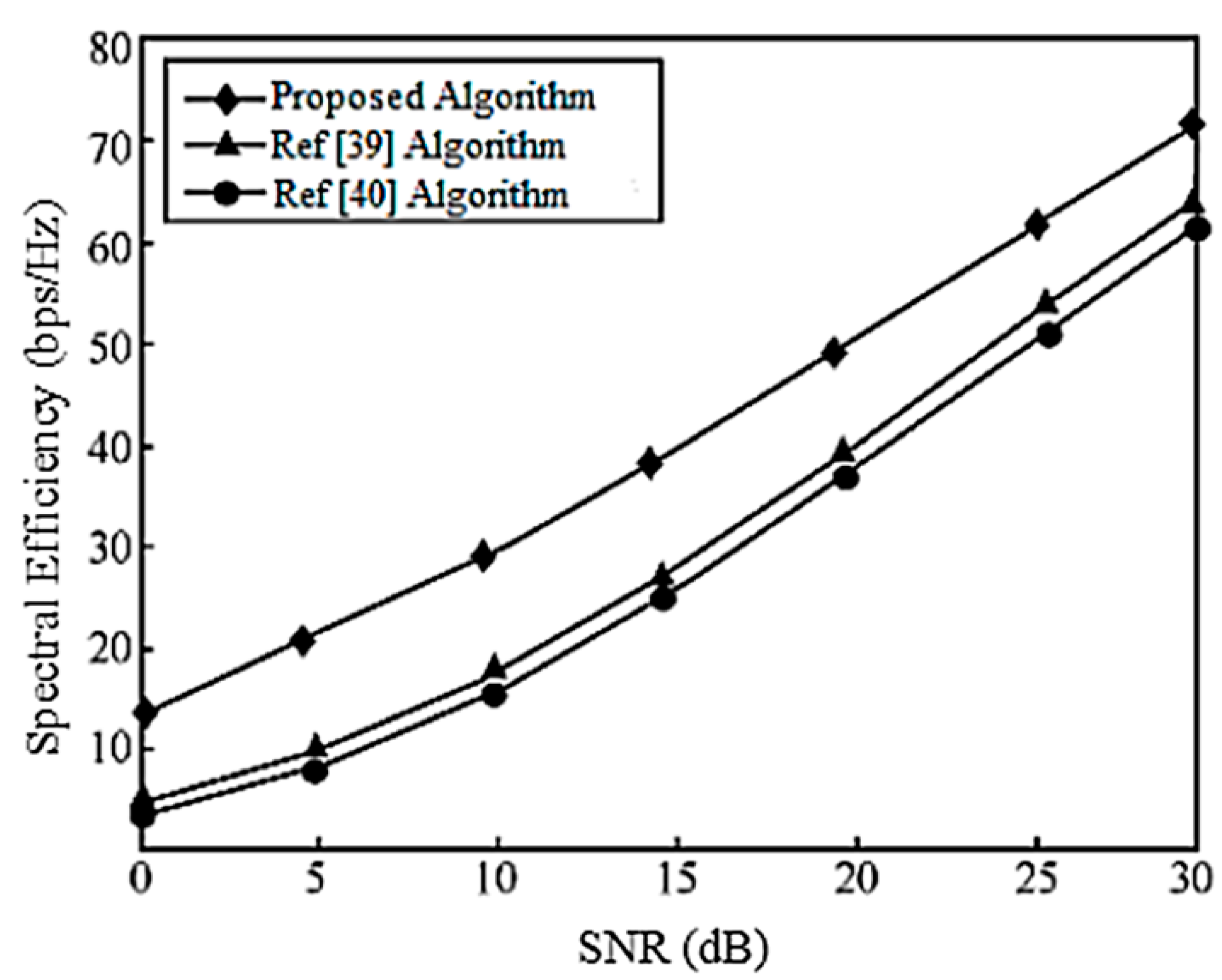
In the configuration of , the DoF of each user is 2, and [39] considers the correlation between user data streams when designing the precoding matrix. Its performance is better than that of [40]. The proposed iterative design of the interference suppression matrix gradually rotates the compression interference, and its performance is better than that of both [39,40].
7.5. Average Spectral Efficiency of Limited Feedback CSI with Equal Loss and High Speeds
This section provides the average spectral efficiency of the proposed algorithm in the high-speed usage case of transmitter and receiver with limited feedback CSI and equal loss. When the system is configured as and , the corresponding average spectral efficiencies are shown in Figure 13 and Figure 14. Here, it is assumed that there is no power loss when the signal propagates to the BS. It can be seen from these two figures that the proposed algorithm is optimal under the two systems configurations because the optimal precoding matrix designed by the algorithm does not require strict interference alignment so that the interference can remain in the signal space. In order to obtain a larger signal to interference and noise ratio, there is more space for placing interference. Because [40] uses the scheme quantizing the channel matrix, its performance is worse than that of [39] due to its large quantization error. In addition, it can also be seen that:
- The bit allocation scheme of this paper improves the spectrum utilization of the algorithm when the feedback is limited.
- The interference leakage caused by the influence of the quantization error is getting larger and larger, which will limit the spectrum efficiency of the system.
8. Conclusions
This paper proposes an efficient Interference Alignment algorithm for maximizing the achievable sum rate and user rate lower-bound of the MIMO-MAC system. In this paper, when the CSI is fed back from the receiver, the performance is deteriorated due to quantization error in the feedback. For this purpose, a direct codeword selection scheme for maximizing the system user rate lower-bound is provided for K users in each cell of 2 cells in a MIMO-MAC environment, and a Bit allocation algorithm is used to reduce system and rate loss. The MAX-SINR algorithm is used at the receiver to decode and maximize the lower-bound of the system user rate. From theoretical analysis and simulation results, we can see that as compared with the existing typical algorithms, the proposed algorithm improves the performance of the system to a large extent. A further extension of this research work is to consider more than two cells and consider different channel models for performance evaluations.
Author Contributions
W.S. analyzed the research work and performed experimentations, S.W.S. provided extensive technical support throughout the research work, J.L. provided extensive support in the theoretical analysis, and I.B. provided the results validation and conclusion. He also provided support in research funding.
Funding
This research was funded by Ministerio de Economía, Industria y Competitividad, Gobierno de España grant number BIA2017-87573-C2-2-P.
Conflicts of Interest
The authors declare no conflict of interest.
References
- Cadambre, V.R.; Jafar, S.A. Interference alignment and degrees of freedom of the K-user interference channel. IEEE Trans. Inf. Theory 2008, 54, 3425–3441. [Google Scholar] [CrossRef]
- Jafar, S.A. Interference alignment-a new look at signal dimensions in a communication network. Found. Trends Commun. Inf. Theory 2011, 7, 1–136. [Google Scholar] [CrossRef]
- Zhang, Y.; Gu, C.; Shu, R.; Zhou, Z.; Zou, W. Interference alignment in multi-user MIMO systems. ICT Express 2015, 1, 5–9. [Google Scholar] [CrossRef]
- Zhang, Y.; Zhao, C.; Meng, J.; Li, S.; Li, L. Adaptive limited feedback for interference alignment in MIMO interference channels. EURASIP J. Wirel. Commun. Netw. 2016. [Google Scholar] [CrossRef] [PubMed]
- Pivaro, G.; Kumar, S.; Fraidenraich, G. On the Exact Distribution of Mutual Information of Two-User MIMO MAC Based on Quotient Distribution of Wishart Matrices. EURASIP J. Wirel. Commun. Netw. 2017, 75, 1–13. [Google Scholar] [CrossRef]
- Ghasemi, A.; Motahari, A.S.; Khandani, A.K. Interference alignment for the K user MIMO Interference channel. In Proceedings of the IEEE International Symposium on Information Theory (ISIT), Austin, TX, USA, 12–18 June 2010. [Google Scholar]
- Zhang, Y.X.; Cheng, R.S. On the design of the interference alignment scheme for multi-user MIMO with limited feedback. In Proceedings of the IEEE International Conference on Communications (ICC), Budapest, Hungary, 9–13 June 2013. [Google Scholar]
- Sara, T.; Adão, S.; Ruid, R.; Gameiro, A. Robust iterative interference alignment with limited feedback. In Proceedings of the IEEE Global Telecommunications Conference (GLOBECOM), San Diego, CA, USA, 6–10 December 2015. [Google Scholar]
- Lee, N.; Shin, W.; Clerckx, B. Interference alignment with limited feedback for two-cell interfering MIMO-MAC. In Proceedings of the International Symposium on Wireless Communication Systems, Paris, France, 28–31 August 2012. [Google Scholar]
- Jan, S.; Gerhard, W.; Peter, J. Robust iterative interference alignment for cellular networks with limited feedback. IEEE Trans. Wirel. Commun. 2015, 14, 882–894. [Google Scholar]
- Li, Y.; Diao, X.; Dong, Q.; Tang, C. Interference alignment based on rank constraint in MIMO cognitive radio networks. Symmetry 2017, 9, 107. [Google Scholar] [CrossRef]
- Kim, M.J.; Lee, H.H.; Ko, Y.C. Limited feedback design for interference alignment on two-cell interfering MIMO-MAC. IEEE Trans. Veh. Technol. 2015, 64, 4019–4030. [Google Scholar] [CrossRef]
- Wang, H.; Shin, R.I.; Leung, S.H. Throughput analysis of interference alignment for a general centralized limited feedback model. IEEE Trans. Veh. Technol. 2016, 65, 8775–8781. [Google Scholar] [CrossRef]
- Gao, H.; Lv, T.; Fang, D.; Yang, S.; Yuen, C. Limited feedback-based interference alignment for interfering multi-access channels. IEEE Commun. Lett. 2014, 18, 540–543. [Google Scholar] [CrossRef]
- Mosleh, S.; Ashdown, J.D.; Mayas, J.D.; Medley, M.J.; Zhang, J.; Liu, L. Interference Alignment for Downlink Multi-Cell LTE-Advanced Systems with Limited Feedback. IEEE Trans. Wirel. Commun. 2016, 15, 8107–8121. [Google Scholar] [CrossRef]
- Hassan, N.; Fernando, X. Massive MIMO wireless networks: An overview. Electronics 2017, 6, 1–29. [Google Scholar] [CrossRef]
- Jeon, S.W.; Gastpar, M. A Survey on interference networks: Interference alignment and neutralization. Entropy 2012, 14, 1842–1863. [Google Scholar] [CrossRef]
- Dong, A.; Shu, H.Z.M.; Yuan, D. Simultaneous wireless information and power transfer for MIMO interference channel networks based on interference alignment. Entropy 2017, 19, 484. [Google Scholar] [CrossRef]
- Kakar, J.; Sezgin, A. A survey on robust interference management in wireless networks. Entropy 2017, 19, 362. [Google Scholar] [CrossRef]
- Jhung, B.C.; Kim, S.M.; Shing, W.Y.; Yang, H.J. Optimal multiuser diversity in multi-cell MIMO uplink networks: User scaling law and beamforming design. Entropy 2017, 19, 393. [Google Scholar] [CrossRef]
- Kocian, A.; Badiu, M.A.; Fleury, B.H.; Martelli, F.; Santi, P. A unified message-passing algorithm for MIMO-SDMA software-defined radio. EURASIP J. Wirel. Commun. Netw. 2017, 4. [Google Scholar] [CrossRef]
- Lameiro, C.; González, Ó.; García-Naya, J.A.; Santamaría, I.; Castedo, L. Experimental evaluation of interference alignment for broadband WLAN systems. EURASIP J. Wirel. Commun. Netw. 2015, 180. [Google Scholar] [CrossRef]
- Pitaval, R.A.; Tirkonen, O.; Blosteing, S.D. Low complexity MIMO precoding codebooks from orthoplex packings. In Proceedings of the IEEE International Conference on Communications (ICC), Kyoto, Japan, 5–9 June 2011. [Google Scholar]
- Khan, I.; Zafar, M.H.; Jan, M.T.; Lloret, J.; Basheri, M.; Singh, D. Spectral and energy efficient low-overhead uplink and downlink channel estimation for 5G massive MIMO systems. Entropy 2018, 20, 92. [Google Scholar] [CrossRef]
- Khan, I.; Singh, M.; Singh, D. Compressive sensing based sparsity adaptive channel estimation for 5G massive MIMO systems. Appl. Sci. 2018, 8, 754. [Google Scholar] [CrossRef]
- Gomadam, K.; Cadambe, V.R.; Jafar, S.A. Distributed numerical approach to interference alignment and applications to wireless interference networks. IEEE Trans. Inf. Theory 2011, 57, 3309–3322. [Google Scholar] [CrossRef]
- Khan, I.; Singh, D. Efficient Compressive Sensing Based Sparse Channel Estimation for 5G Massive MIMO Systems. Int. J. Electron. Commun. 2018, 89, 181–190. [Google Scholar] [CrossRef]
- Kim, J.S.; Moon, S.H.; Lee, S.R.; Lee, I. A new channel quantization strategy for MIMO interference alignment with limited feedback. IEEE Trans. Wirel. Commun. 2012, 11, 358–366. [Google Scholar] [CrossRef]
- Ayach, E.O.; Heath, R.W., Jr. Grassmannian differential limited feedback for interference alignment. IEEE Trans. Signal Process. 2012, 60, 6481–6494. [Google Scholar] [CrossRef]
- Thukral, J.; Olcskei, H.B. Interference alignment with limited feedback. In Proceedings of the IEEE International Symposium on Information Theory, Seoul, Korea, 28 June–3 July 2009. [Google Scholar]
- Guillaud, R.M. Limited feedback for interference alignment in the K-user MIMO interference channel. In Proceedings of the IEEE Information Theory Workshop, Lausanne, Switzerland, 3–7 September 2012. [Google Scholar]
- Zhou, R.; Lv, T.; Gao, H.; Long, W.; Lu, Y. A new limited feedback scheme for interference alignment in two-cell interfering MIMO-MAC. In Proceedings of the IEEE 23rd International Symposium on Personal Indoor and Mobile Radio Communications, Sydney, Australia, 9–12 September 2012. [Google Scholar]
- Zhou, R.; Lv, T.; Long, W.; Gao, H.; Lu, Y.; Liu, E. Limited feedback schemes based on ICI alignment in two-cell interfering MIMO-MAC. In Proceedings of the IEEE International Conference on Communications (ICC), Budapest, Hungary, 9–13 June 2013. [Google Scholar]
- Cho, S.; Huang, K.; Kim, D.; Seo, H. Interference alignment for uplink cellular systems with limited feedback. IEEE Commun. Lett. 2012, 16, 960–963. [Google Scholar] [CrossRef]
- Krishnamachari, R.T.; Varanasi, M.K. Interference alignment under limited feedback for MIMO interference channels. In Proceedings of the IEEE International Symposium on Information Theory (ISIT), Austin, TX, USA, 12–18 June 2010. [Google Scholar]
- Chen, X.; Yuen, C. Performance analysis and optimization for interference alignment over MIMO interference channels with limited feedback. IEEE Trans. Signal Process. 2014, 62, 1785–1795. [Google Scholar] [CrossRef]
- Suh, C.; Minnie, H.; Tse, D. Downlink interference alignment. IEEE Trans. Commun. 2011, 59, 2616–2626. [Google Scholar] [CrossRef]
- Dai, W.; Liu, Y.; Rider, B. Quantization bounds on Grassmann manifolds and applications to MIMO communications. IEEE Trans. Inf. Theory 2008, 54, 1108–1123. [Google Scholar] [CrossRef]
- Selvaprabhu, P.; Chinnadurai, S.; Sarker, M.A.L.; Lee, M.H. Joint interference alignment and power allocation for k-user multicell MIMO channel through staggered antenna switching. Sensors 2018, 18, 380. [Google Scholar] [CrossRef] [PubMed]
- Mohsen, R.; Maxime, G. Interference alignment with quantized grassmannian feedback in the k-user constant MIMO interference channel. IEEE Trans. Wirel. Commun. 2016, 15, 1456–1468. [Google Scholar]
Figure 1.
Proposed two-cell multiple-input multiple-output (MIMO)-MAC system model with users.

Figure 2.
Spectral efficiency analysis of the system configuration.

Figure 3.
Spectral efficiency analysis of the system configuration.

Figure 4.
Spectral efficiency analysis of the system configuration when bit = 6. CSI = Channel State Information.
Figure 4.
Spectral efficiency analysis of the system configuration when bit = 6. CSI = Channel State Information.

Figure 5.
Spectral efficiency analysis of the system configuration when bit = 8.

Figure 6.
The average lower limit of the system user rate at and bit = 6.

Figure 7.
The average lower limit of the system user rate at and bit = 8.

Figure 8.
Algorithm complexity with limited feedback bit = 8.

Figure 9.
Spectral efficiency analysis of the system configuration with a total number of feedback bits .
Figure 9.
Spectral efficiency analysis of the system configuration with a total number of feedback bits .

Figure 10.
Spectral efficiency analysis of the system configuration with a total number of feedback bits .
Figure 10.
Spectral efficiency analysis of the system configuration with a total number of feedback bits .

Figure 11.
Spectral efficiency analysis of the system configuration.

Figure 12.
Spectral efficiency analysis of the system configuration.

Figure 13.
Spectral efficiency analysis of the system configuration when bit = 24.

Figure 14.
Spectral efficiency analysis of the system configuration when bit = 32.

© 2018 by the authors. Licensee MDPI, Basel, Switzerland. This article is an open access article distributed under the terms and conditions of the Creative Commons Attribution (CC BY) license (http://creativecommons.org/licenses/by/4.0/).
Share and Cite
MDPI and ACS Style
Shahjehan, W.; Shah, S.W.; Lloret, J.; Bosch, I. A Novel Codeword Selection Scheme for MIMO-MAC Lower-Bound Maximization. Entropy 2018, 20, 546. https://0-doi-org.brum.beds.ac.uk/10.3390/e20080546
AMA Style
Shahjehan W, Shah SW, Lloret J, Bosch I. A Novel Codeword Selection Scheme for MIMO-MAC Lower-Bound Maximization. Entropy. 2018; 20(8):546. https://0-doi-org.brum.beds.ac.uk/10.3390/e20080546
Chicago/Turabian StyleShahjehan, Waleed, Syed Waqar Shah, Jaime Lloret, and Ignacio Bosch. 2018. "A Novel Codeword Selection Scheme for MIMO-MAC Lower-Bound Maximization" Entropy 20, no. 8: 546. https://0-doi-org.brum.beds.ac.uk/10.3390/e20080546
Note that from the first issue of 2016, this journal uses article numbers instead of page numbers. See further details here.