
Novel, Stable Catholyte for Aqueous Organic Redox Flow Batteries: Symmetric Cell Study of Hydroquinones with High Accessible Capacity

 ,
, 
 and
and
Abstract
:
1. Introduction
2. Results
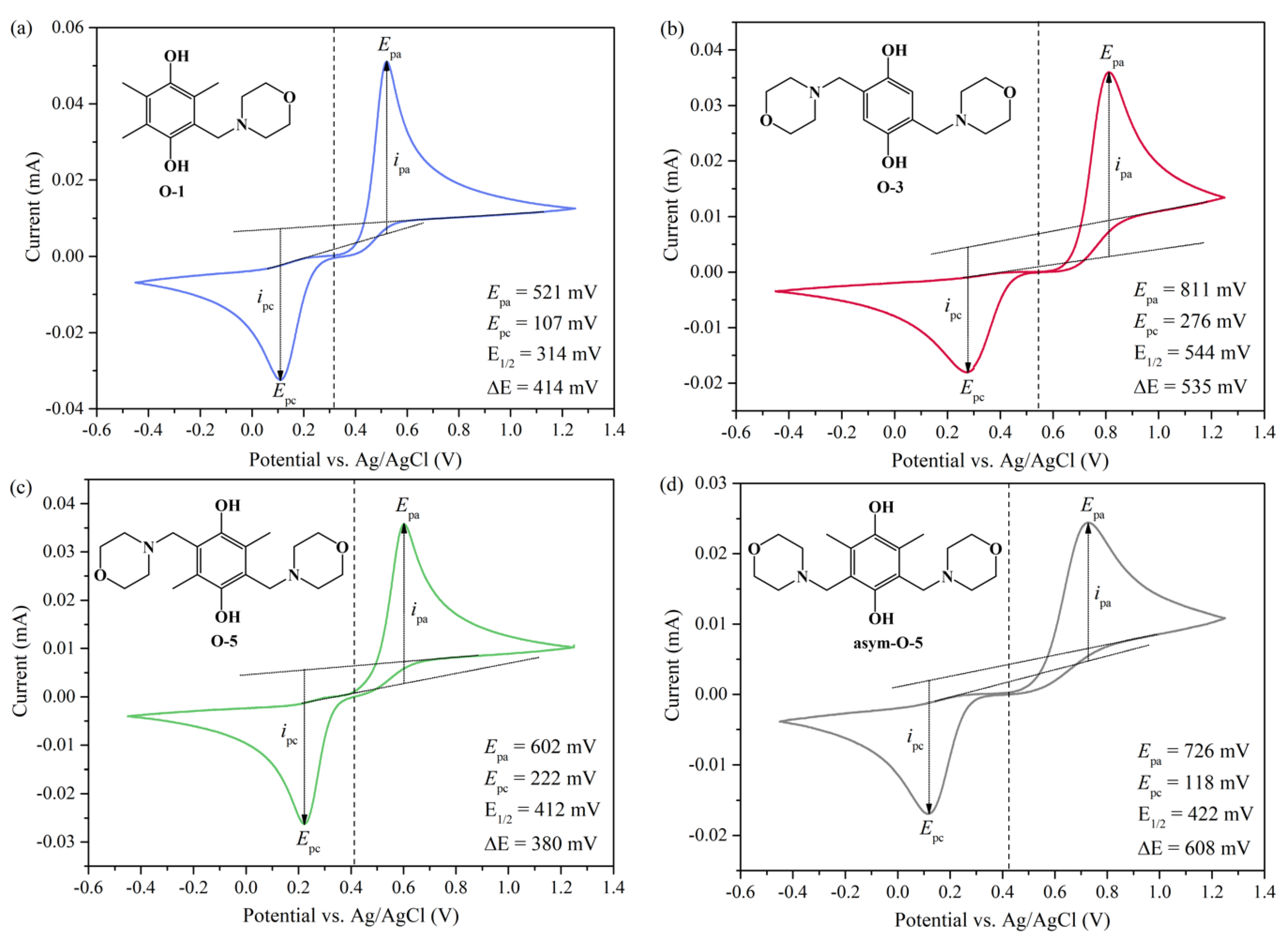
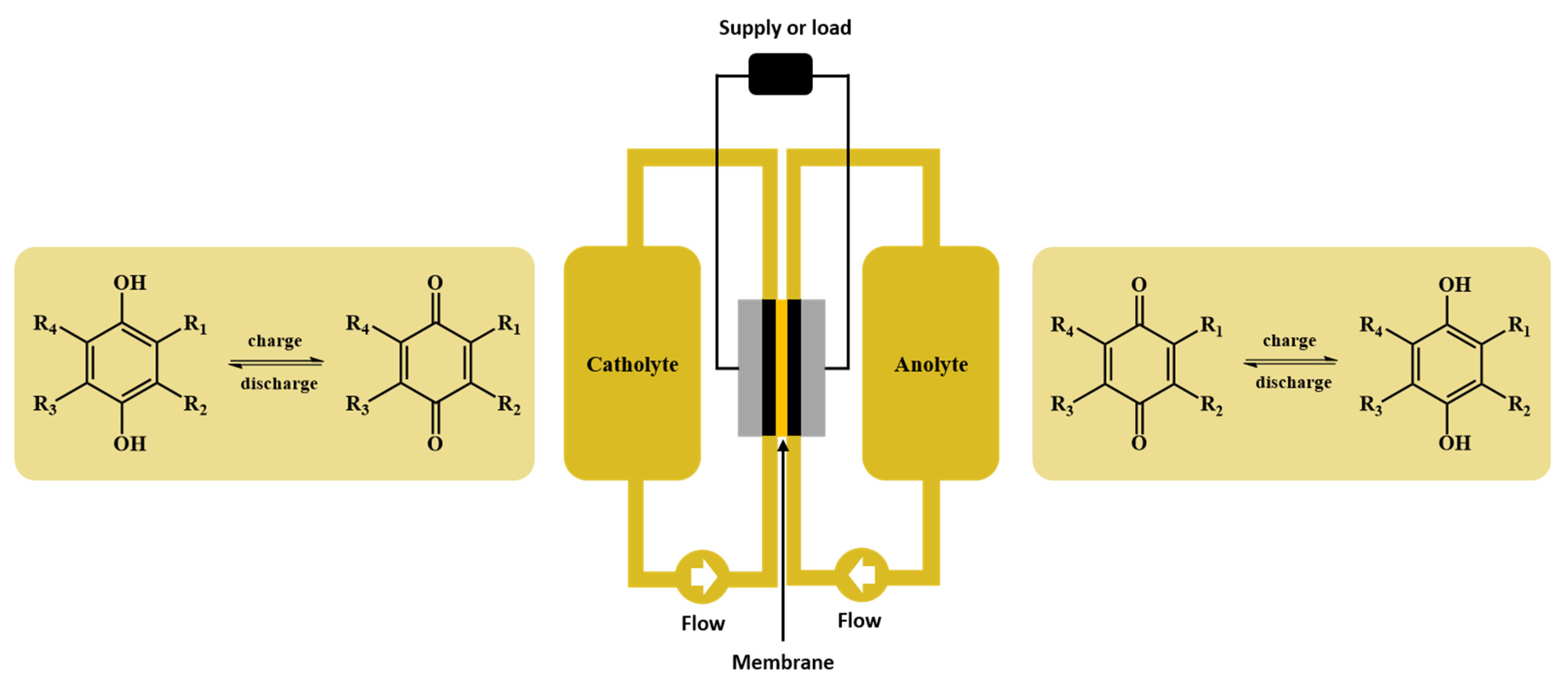
2.1. Reversibility and Redox Potential
2.2. Symmetric Cell Cycling Tests
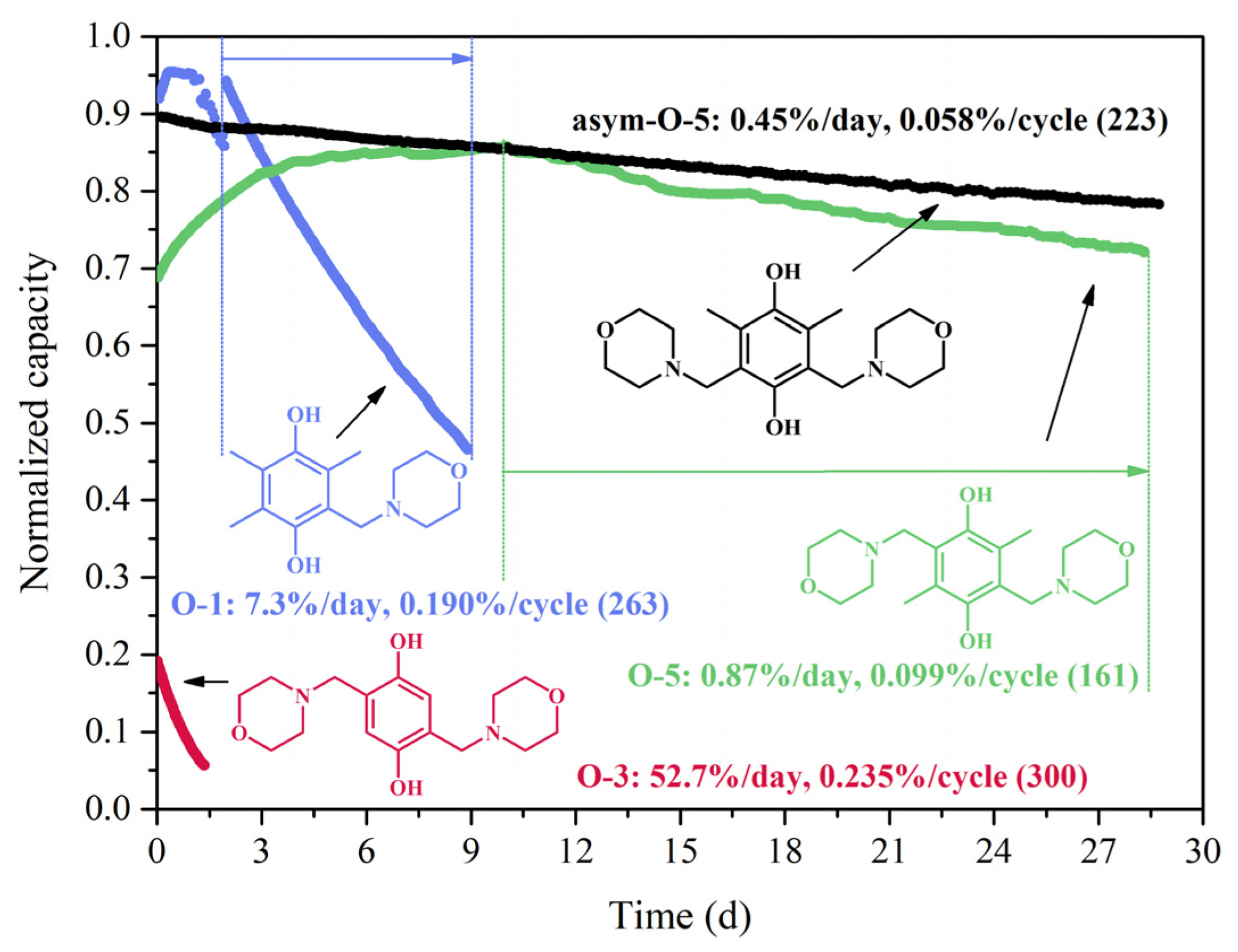
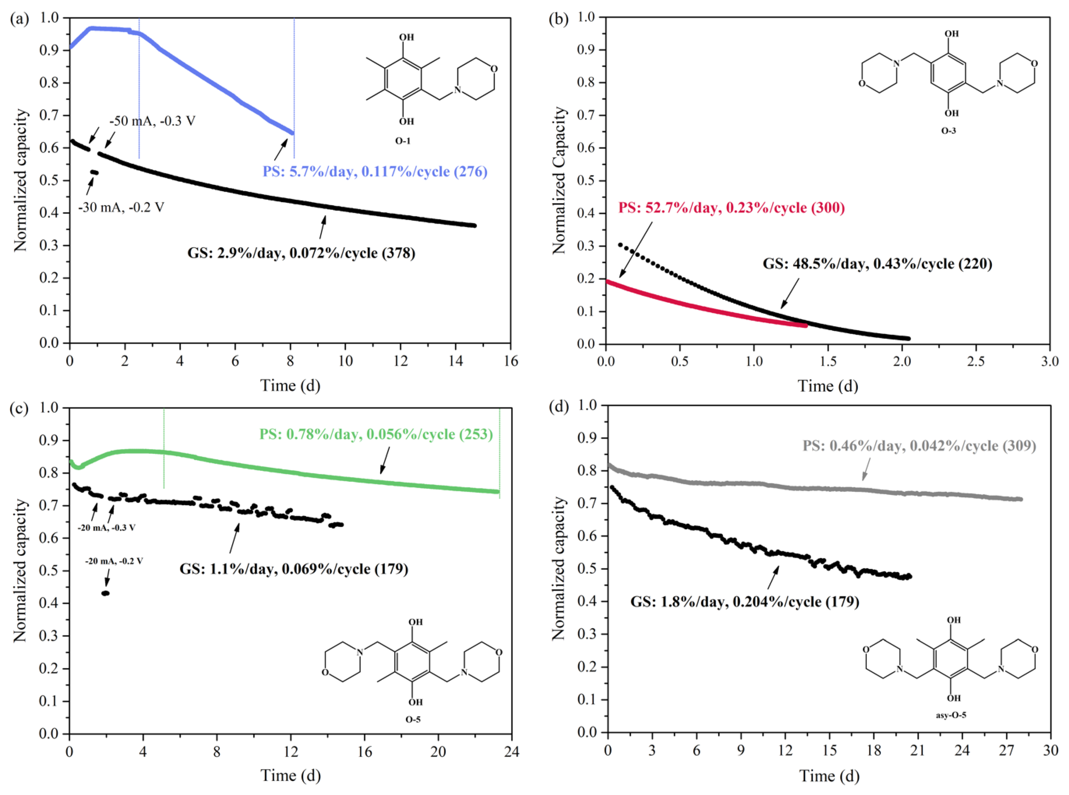
2.2.1. Stability
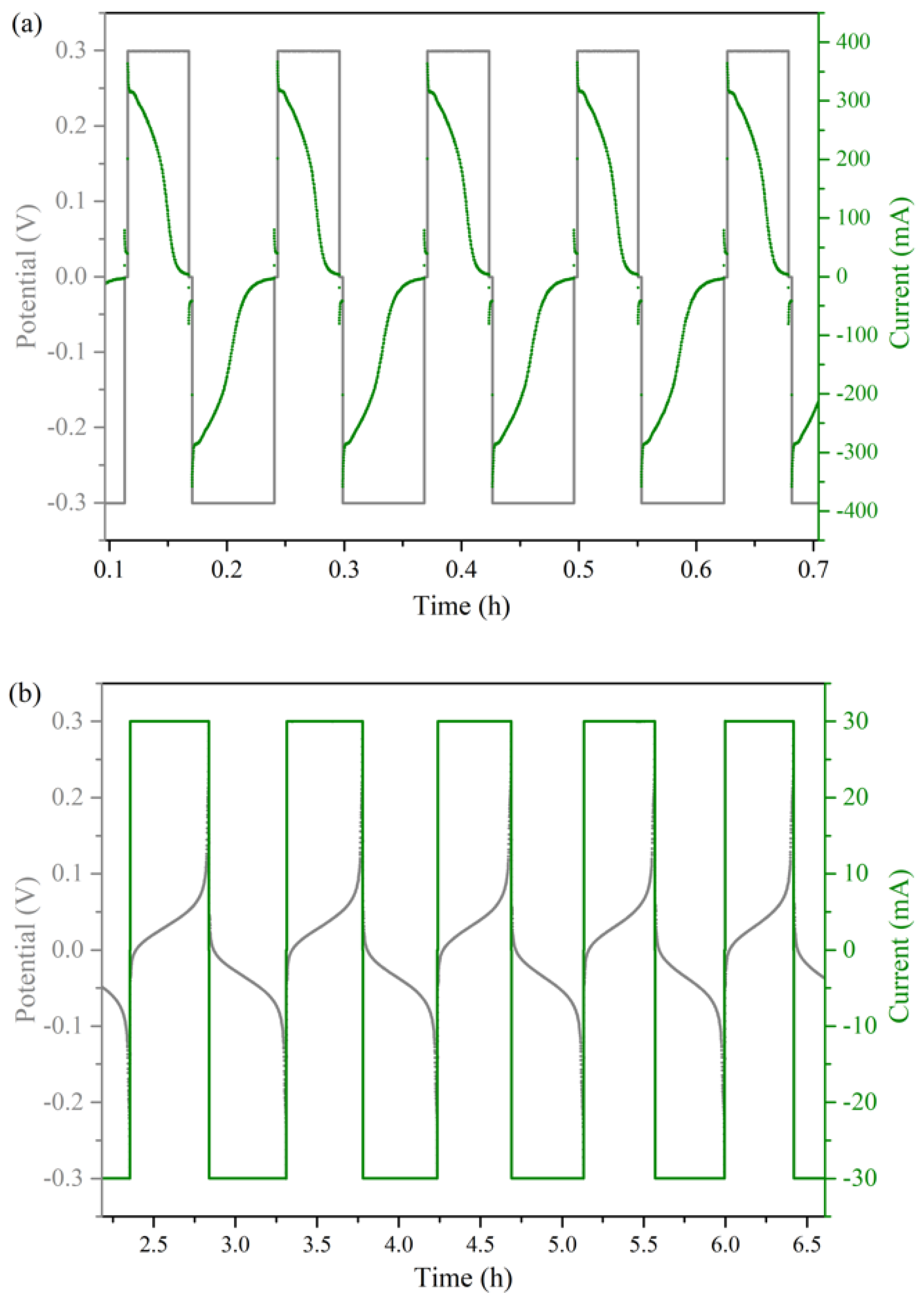
2.2.2. PS vs. GS Cycling Method
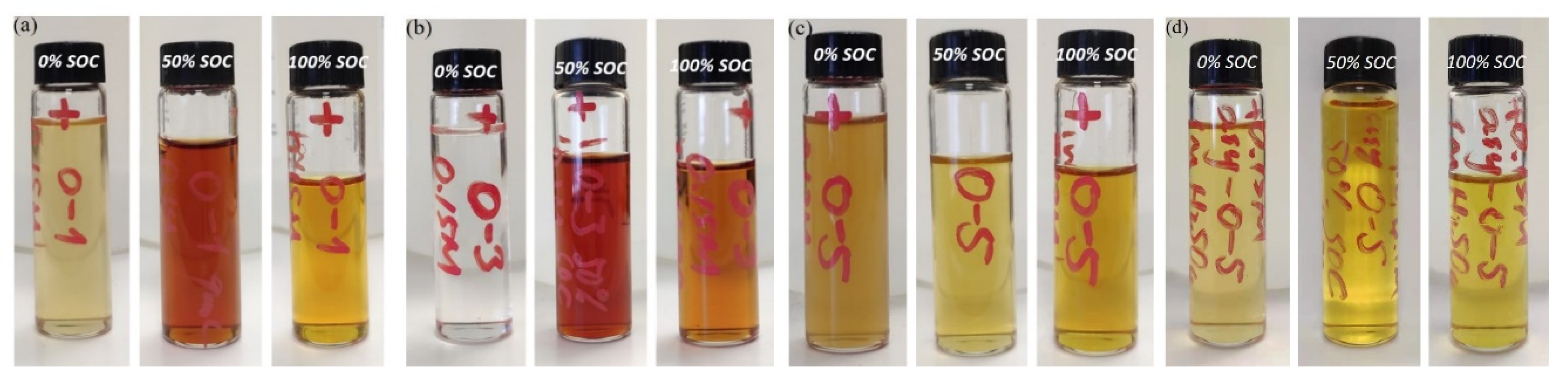
2.2.3. Accessible Capacity
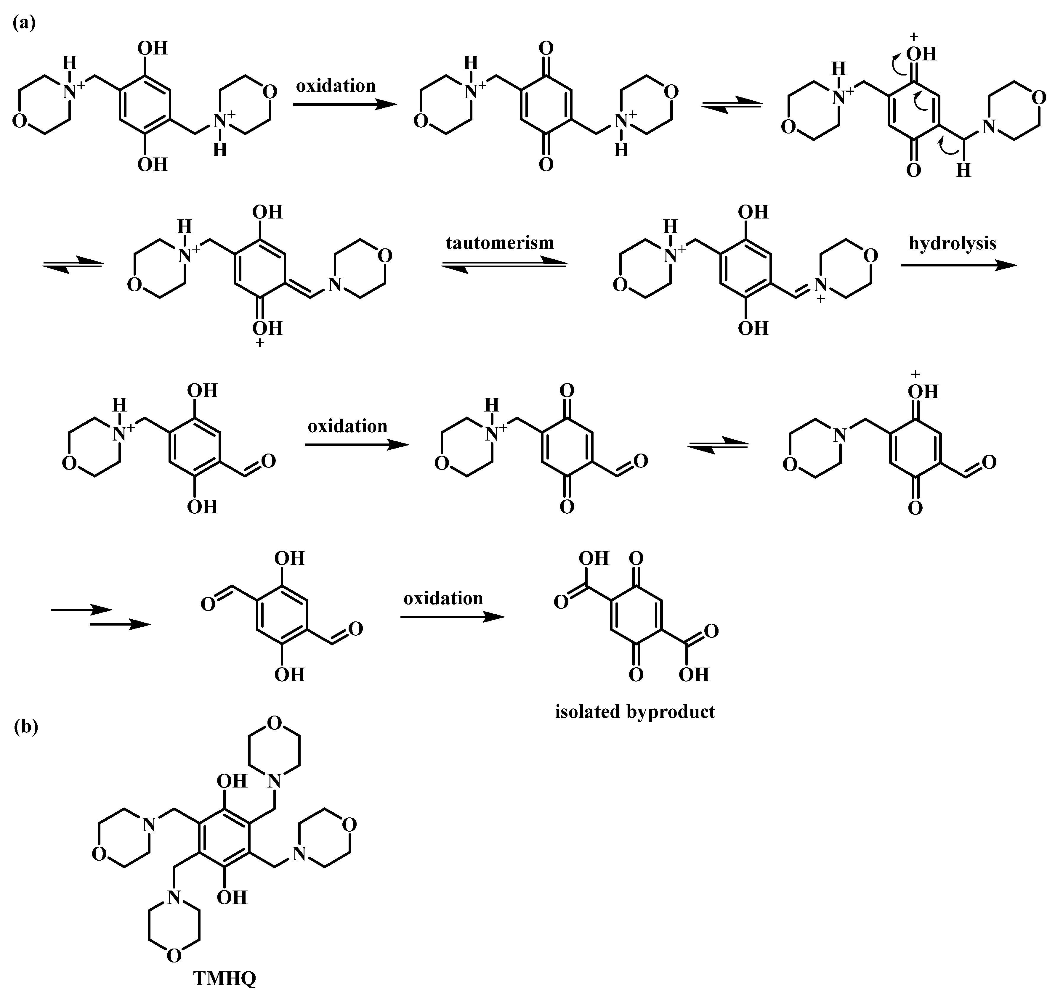
3. Discussion
4. Materials and Methods
4.1. Synthesis, Analytical Description and Solubility Measurements
4.2. Cyclic Voltammetry
4.3. Preparation of Electrolyte Solutions
4.4. Symmetric Cell Cycling Tests
5. Conclusions
Author Contributions
Funding
Institutional Review Board Statement
Informed Consent Statement
Data Availability Statement
Conflicts of Interest
Sample Availability
Appendix A


| Condition | Current (mA) | Cell Resistance (Ω) |
|---|---|---|
| 19 mL 0.05 M O-1 in 1 M H2SO4 | 50 | 0.135/0.120 |
| 9 mL 0.1 M O-3 in 1 M H3PO4 | 30 | 0.456/0.357 |
| 7 mL 0.075 M O-5 in 1 M H2SO4 | 20 | 0.169/0.160 |
| 9 mL 0.1 M asym-O-5 in 1 M H2SO4 | 20 | 0.134/0.122 |

References
- Winsberg, J.; Hagemann, T.; Janoschka, T.; Hager, M.D.; Schubert, U.S. Redox-Flow Batteries: From Metals to Organic Redox-Active Materials. Angew. Chem. Int. Ed. 2017, 56, 686–711. [Google Scholar] [CrossRef]
- Wang, W.; Sprenkle, V. Energy storage: Redox flow batteries go organic. Nat. Chem. 2016, 8, 204–206. [Google Scholar] [CrossRef]
- Xu, Y.; Wen, Y.-H.; Cheng, J.; Cao, G.-P.; Yang, Y.-S. A study of tiron in aqueous solutions for redox flow battery application. Electrochim. Acta 2010, 55, 715–720. [Google Scholar] [CrossRef]
- Wedege, K.; Drazevic, E.; Konya, D.; Bentien, A. Organic Redox Species in Aqueous Flow Batteries: Redox Potentials, Chemical Stability and Solubility. Sci. Rep. 2016, 6, 39101. [Google Scholar] [CrossRef] [Green Version]
- Wei, X.; Pan, W.; Duan, W.; Hollas, A.; Yang, Z.; Li, B.; Nie, Z.; Liu, J.; Reed, D.; Wang, W.; et al. Materials and Systems for Organic Redox Flow Batteries: Status and Challenges. ACS Energy Lett. 2017, 2, 2187–2204. [Google Scholar] [CrossRef]
- Janoschka, T.; Friebe, C.; Hager, M.D.; Martin, N.; Schubert, U.S. An Approach Toward Replacing Vanadium: A Single Organic Molecule for the Anode and Cathode of an Aqueous Redox-Flow Battery. ChemistryOpen 2017, 6, 216–220. [Google Scholar] [CrossRef] [PubMed]
- Hagemann, T.; Winsberg, J.; Grube, M.; Nischang, I.; Janoschka, T.; Martin, N.; Hager, M.D.; Schubert, U.S. An aqueous all-organic redox-flow battery employing a (2,2,6,6-tetramethylpiperidin-1-yl)oxyl-containing polymer as catholyte and dimethyl viologen dichloride as anolyte. J. Power Sources 2018, 378, 546–554. [Google Scholar] [CrossRef]
- Hagemann, T.; Strumpf, M.; Schröter, E.; Stolze, C.; Grube, M.; Nischang, I.; Hager, M.D.; Schubert, U.S. (2,2,6,6-Tetramethylpiperidin-1-yl)oxyl-Containing Zwitterionic Polymer as Catholyte Species for High-Capacity Aqueous Polymer Redox Flow Batteries. Chem. Mater. 2019, 31, 7987–7999. [Google Scholar] [CrossRef]
- Janoschka, T.; Martin, N.; Martin, U.; Friebe, C.; Morgenstern, S.; Hiller, H.; Hager, M.D.; Schubert, U.S. An aqueous, polymer-based redox-flow battery using non-corrosive, safe, and low-cost materials. Nature 2015, 527, 78–81. [Google Scholar] [CrossRef]
- Khataee, A.; Dražević, E.; Catalano, J.; Bentien, A. Performance Optimization of Differential pH Quinone-Bromide Redox Flow Battery. J. Electrochem. Soc. 2018, 165, A3918–A3924. [Google Scholar] [CrossRef] [Green Version]
- Lee, W.; Permatasari, A.; Kwon, B.W.; Kwon, Y. Performance evaluation of aqueous organic redox flow battery using anthraquinone-2,7-disulfonic acid disodium salt and potassium iodide redox couple. Chem. Eng. J. 2019, 358, 1438–1445. [Google Scholar] [CrossRef]
- Leung, P.; Shah, A.A.; Sanz, L.; Flox, C.; Morante, J.R.; Xu, Q.; Mohamed, M.R.; Ponce de León, C.; Walsh, F.C. Recent developments in organic redox flow batteries: A critical review. J. Power Sources 2017, 360, 243–283. [Google Scholar] [CrossRef] [Green Version]
- Lin, K.; Chen, Q.; Gerhardt, M.R.; Tong, L.; Kim, S.B.; Eisenach, L.; Valle, A.W.; Hardee, D.; Gordon, R.G.; Aziz, M.J.; et al. Alkaline quinone flow battery. Science 2015, 349, 1529–1532. [Google Scholar] [CrossRef] [PubMed] [Green Version]
- Janoschka, T.; Martin, N.; Hager, M.D.; Schubert, U.S. An Aqueous Redox-Flow Battery with High Capacity and Power: The TEMPTMA/MV System. Angew. Chem. Int. Ed. 2016, 55, 14427–14430. [Google Scholar] [CrossRef]
- Luca, O.R.; Gustafson, J.L.; Maddox, S.M.; Fenwick, A.Q.; Smith, D.C. Catalysis by electrons and holes: Formal potential scales and preparative organic electrochemistry. Org. Chem. Front. 2015, 2, 823–848. [Google Scholar] [CrossRef] [Green Version]
- Gong, K.; Fang, Q.; Gu, S.; Li, S.F.Y.; Yan, Y. Nonaqueous redox-flow batteries: Organic solvents, supporting electrolytes, and redox pairs. Energy Environ. Sci. 2015, 8, 3515–3530. [Google Scholar] [CrossRef] [Green Version]
- Hu, B.; DeBruler, C.; Rhodes, Z.; Liu, T.L. Long-Cycling Aqueous Organic Redox Flow Battery (AORFB) toward Sustainable and Safe Energy Storage. J. Am. Chem. Soc. 2017, 139, 1207–1214. [Google Scholar] [CrossRef]
- Reichardt, C.; Welton, T. Solvents and Solvent Effects in Organic Chemistry; John Wiley & Sons: Weinheim, Germany, 2011. [Google Scholar]
- Kucharyson, J.F.; Cheng, L.; Tung, S.O.; Curtiss, L.A.; Thompson, L.T. Predicting the potentials, solubilities and stabilities of metal-acetylacetonates for non-aqueous redox flow batteries using density functional theory calculations. J. Mater. Chem. A 2017, 5, 13700–13709. [Google Scholar] [CrossRef]
- Cheng, L.; Assary, R.S.; Qu, X.; Jain, A.; Ong, S.P.; Rajput, N.N.; Persson, K.; Curtiss, L.A. Accelerating Electrolyte Discovery for Energy Storage with High-Throughput Screening. J. Phys. Chem. Lett. 2015, 6, 283–291. [Google Scholar] [CrossRef] [PubMed]
- Er, S.; Suh, C.; Marshak, M.P.; Aspuru-Guzik, A. Computational design of molecules for an all-quinone redox flow battery. Chem. Sci. 2015, 6, 885–893. [Google Scholar] [CrossRef] [Green Version]
- Bachman, J.E.; Curtiss, L.A.; Assary, R.S. Investigation of the redox chemistry of anthraquinone derivatives using density functional theory. J. Phys. Chem. A 2014, 118, 8852–8860. [Google Scholar] [CrossRef]
- Huskinson, B.; Marshak, M.P.; Suh, C.; Er, S.; Gerhardt, M.R.; Galvin, C.J.; Chen, X.; Aspuru-Guzik, A.; Gordon, R.G.; Aziz, M.J. A metal-free organic-inorganic aqueous flow battery. Nature 2014, 505, 195–198. [Google Scholar] [CrossRef] [PubMed]
- Carney, T.J.; Collins, S.J.; Moore, J.S.; Brushett, F.R. Concentration-Dependent Dimerization of Anthraquinone Disulfonic Acid and Its Impact on Charge Storage. Chem. Mater 2017, 29, 4801–4810. [Google Scholar] [CrossRef]
- Wiberg, C.; Carney, T.J.; Brushett, F.; Ahlberg, E.; Wang, E. Dimerization of 9,10-anthraquinone-2,7-Disulfonic acid (AQDS). Electrochim. Acta 2019, 317, 478–485. [Google Scholar] [CrossRef]
- Ding, Y.; Li, Y.; Yu, G. Exploring Bio-inspired Quinone-Based Organic Redox Flow Batteries: A Combined Experimental and Computational Study. Chemistry 2016, 1, 790–801. [Google Scholar] [CrossRef] [Green Version]
- Yang, B.; Hoober-Burkhardt, L.; Wang, F.; Surya Prakash, G.K.; Narayanan, S.R. An Inexpensive Aqueous Flow Battery for Large-Scale Electrical Energy Storage Based on Water-Soluble Organic Redox Couples. J. Electrochem. Soc. 2014, 161, A1371–A1380. [Google Scholar] [CrossRef] [Green Version]
- Hoober-Burkhardt, L.; Krishnamoorthy, S.; Yang, B.; Murali, A.; Nirmalchandar, A.; Prakash, G.K.S.; Narayanan, S.R. A New Michael-Reaction-Resistant Benzoquinone for Aqueous Organic Redox Flow Batteries. J. Electrochem. Soc. 2017, 164, A600–A607. [Google Scholar] [CrossRef]
- Tabor, D.P.; Gómez-Bombarelli, R.; Tong, L.; Gordon, R.G.; Aziz, M.J.; Aspuru-Guzik, A. Mapping the frontiers of quinone stability in aqueous media: Implications for organic aqueous redox flow batteries. J. Mater. Chem. A 2019, 7, 12833–12841. [Google Scholar] [CrossRef]
- Drazevic, E.; Szabo, C.; Konya, D.; Lund, T.; Wedege, K.; Bentien, A. Investigation of Tetramorpholinohydroquinone as a Potential Catholyte in a Flow Battery. ACS Appl. Energy Mater. 2019, 2, 4745–4754. [Google Scholar] [CrossRef] [Green Version]
- Garcia, S.N.; Yang, X.; Bereczki, L.; Konya, D. Aqueous Solubility of Organic Compounds for Flow Battery Applications: Symmetry and Counter Ion Design to Avoid Low-Solubility Polymorphs. Molecules 2021, 26, 1203. [Google Scholar] [CrossRef]
- Ma, L.; Wang, Z.; Li, Q. Study on electrochemical oxidation behaviors and the diffusion mechanism of hydroquinone at pre-anodized carbon paste electrode by cyclic voltammetry. Analyst 2012, 137, 432–436. [Google Scholar] [CrossRef]
- Goulet, M.-A.; Aziz, M.J. Flow Battery Molecular Reactant Stability Determined by Symmetric Cell Cycling Methods. J. Electrochem. Soc. 2018, 165, A1466–A1477. [Google Scholar] [CrossRef] [Green Version]
- Kwabi, D.G.; Ji, Y.; Aziz, M.J. Electrolyte Lifetime in Aqueous Organic Redox Flow Batteries: A Critical Review. Chem. Rev. 2020, 120, 6467–6489. [Google Scholar] [CrossRef]
- Beh, E.S.; De Porcellinis, D.; Gracia, R.L.; Xia, K.T.; Gordon, R.G.; Aziz, M.J. A Neutral pH Aqueous Organic–Organometallic Redox Flow Battery with Extremely High Capacity Retention. ACS Energy Lett. 2017, 2, 639–644. [Google Scholar] [CrossRef]
- Broadbent, A.D.; Melanson, R.J. The Redox Behavior of 9,10-Anthraquinone-2-sulfonate in Acidic Aqueous Solution. Can. J. Chem. 1975, 53, 3757–3760. [Google Scholar] [CrossRef]
- Li, W.; Fu, H.C.; Li, L.; Caban-Acevedo, M.; He, J.H.; Jin, S. Integrated Photoelectrochemical Solar Energy Conversion and Organic Redox Flow Battery Devices. Angew. Chem. Int. Ed. 2016, 55, 13104–13108. [Google Scholar] [CrossRef] [PubMed]
- Zhang, S.; Li, X.; Chu, D. An Organic Electroactive Material for Flow Batteries. Electrochim. Acta 2016, 190, 737–743. [Google Scholar] [CrossRef]
- Cao, J.; Zhu, Z.; Xu, J.; Tao, M.; Chen, Z. Nitrogen-doped porous graphene as a highly efficient cathodic electrocatalyst for aqueous organic redox flow battery application. J. Mater. Chem. A 2017, 5, 7944–7951. [Google Scholar] [CrossRef]
- Yang, Z.; Tong, L.; Tabor, D.P.; Beh, E.S.; Goulet, M.-A.; De Porcellinis, D.; Aspuru-Guzik, A.; Gordon, R.G.; Aziz, M.J. Alkaline Benzoquinone Aqueous Flow Battery for Large-Scale Storage of Electrical Energy. Adv. Energy Mater. 2018, 8, 1702056. [Google Scholar] [CrossRef]
- Darling, R.M.; Perry, M.L. Half-Cell, Steady-State Flow-Battery Experiments. ECS Trans. 2013, 53, 31–38. [Google Scholar] [CrossRef]
- Milshtein, J.D.; Barton, J.L.; Darling, R.M.; Brushett, F.R. 4-acetamido-2,2,6,6-tetramethylpiperidine-1-oxyl as a model organic redox active compound for nonaqueous flow batteries. J. Power Sources 2016, 327, 151–159. [Google Scholar] [CrossRef] [Green Version]
- Milshtein, J.D.; Kaur, A.P.; Casselman, M.D.; Kowalski, J.A.; Modekrutti, S.; Zhang, P.L.; Harsha Attanayake, N.; Elliott, C.F.; Parkin, S.R.; Risko, C.; et al. High current density, long duration cycling of soluble organic active species for non-aqueous redox flow batteries. Energy Environ. Sci. 2016, 9, 3531–3543. [Google Scholar] [CrossRef]


| Condition | Method | Cell Resistance/Ω | Capacity Decay Rate (Cycle) |
|---|---|---|---|
| O-1: 0.05M, 1 M H2SO4 | GS | 0.135/0.120 | 2.9%/day, 0.072%/cycle (378) |
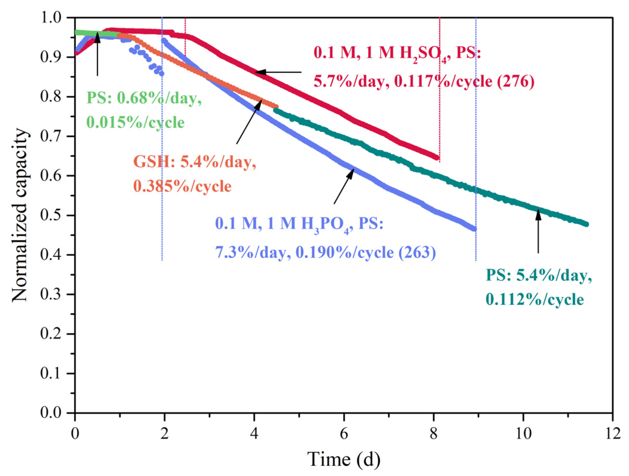
| O-1: 0.1 M, 1 M H2SO4 | PS | 0.175/0.116 | 5.7%/day, 0.117%/cycle (276) |
| O-3: 0.1 M, 1 M H3PO4 | GS | 0.456/0.357 | 48.5%/day, 0.43%/cycle (221) |
| O-3: 0.1 M, 1 M H3PO4 | PS | 0.380/0.346 | 52.7%/day, 0.235%/cycle (300) |
| O-5: 0.075 M, 1 M H2SO4 | GS | 0.169/0.160 | 1.1%/day, 0.069%/cycle (179) |
| O-5: 0.05 M, 1 M H2SO4 | PS | 0.155/0.125 | 0.78%/day, 0.056%/cycle (253) |
| Asym-O-5: 0.1 M, 1 M H2SO4 | GS | 0.134/0.122 | 1.8%/day, 0.204%/cycle (179) |
| Asym-O-5: 0.1 M, 1 M H2SO4 | PS | 0.144/0.128 | 0.46%/day, 0.042%/cycle (309) |
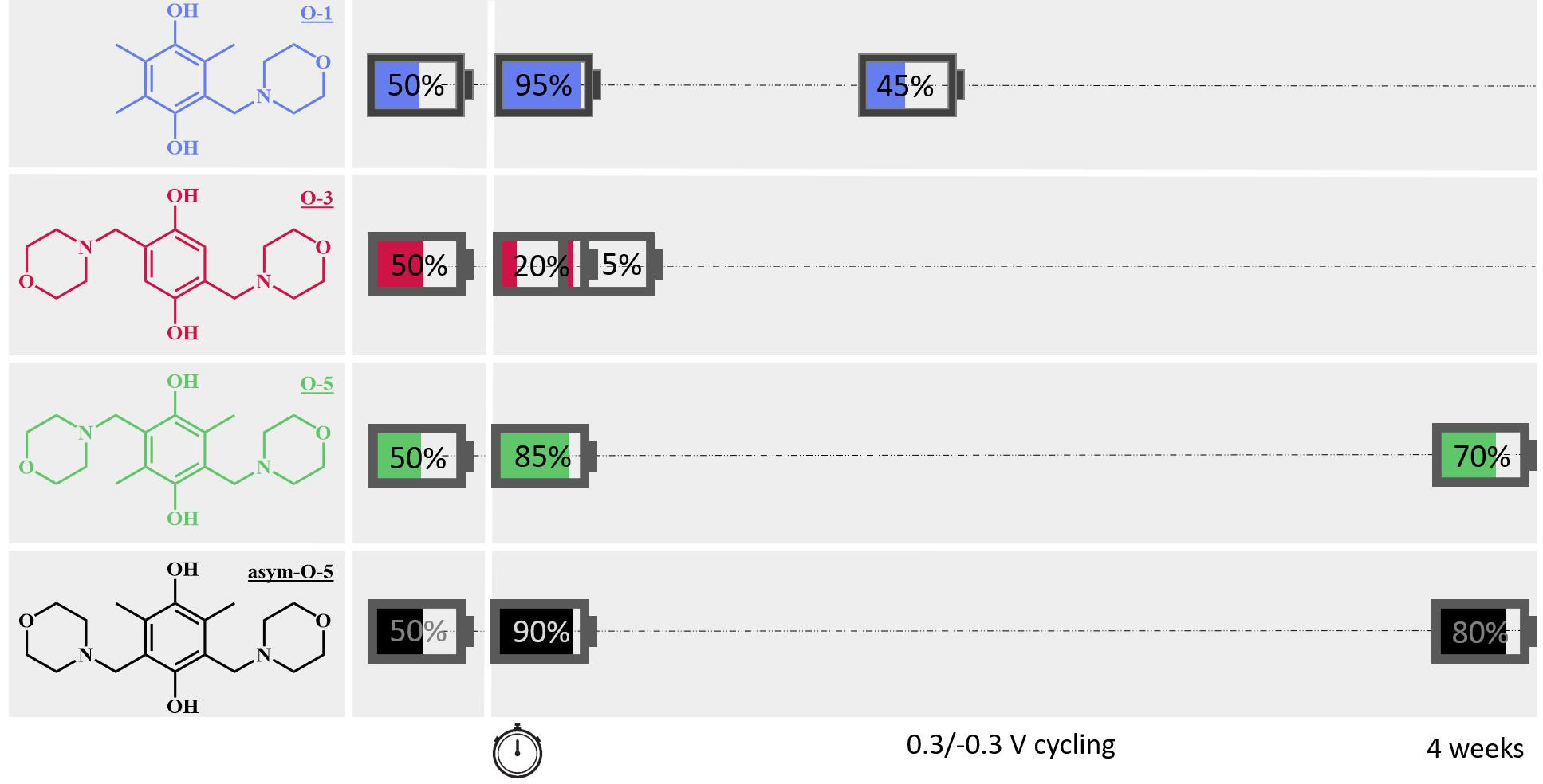
| Catholyte | Anolyte | Accessible Capacity |
|---|---|---|
| 0.1 M O-1 in 1 M H3PO4 | 0.1 M O-1 in 1 M H3PO4 | 96% |
| 0.1 M O-3 in 1 M H3PO4 | 0.1 M O-3 in 1 M H3PO4 | 20% |
| 0.1 M O-5 in 1 M H3PO4 | 0.1 M O-5 in 1 M H3PO4 | 85% |
| 0.1 M asym-O-5 in 1 M H3PO4 | 0.1 M asym-O-5 in 1 M H3PO4 | 90% |
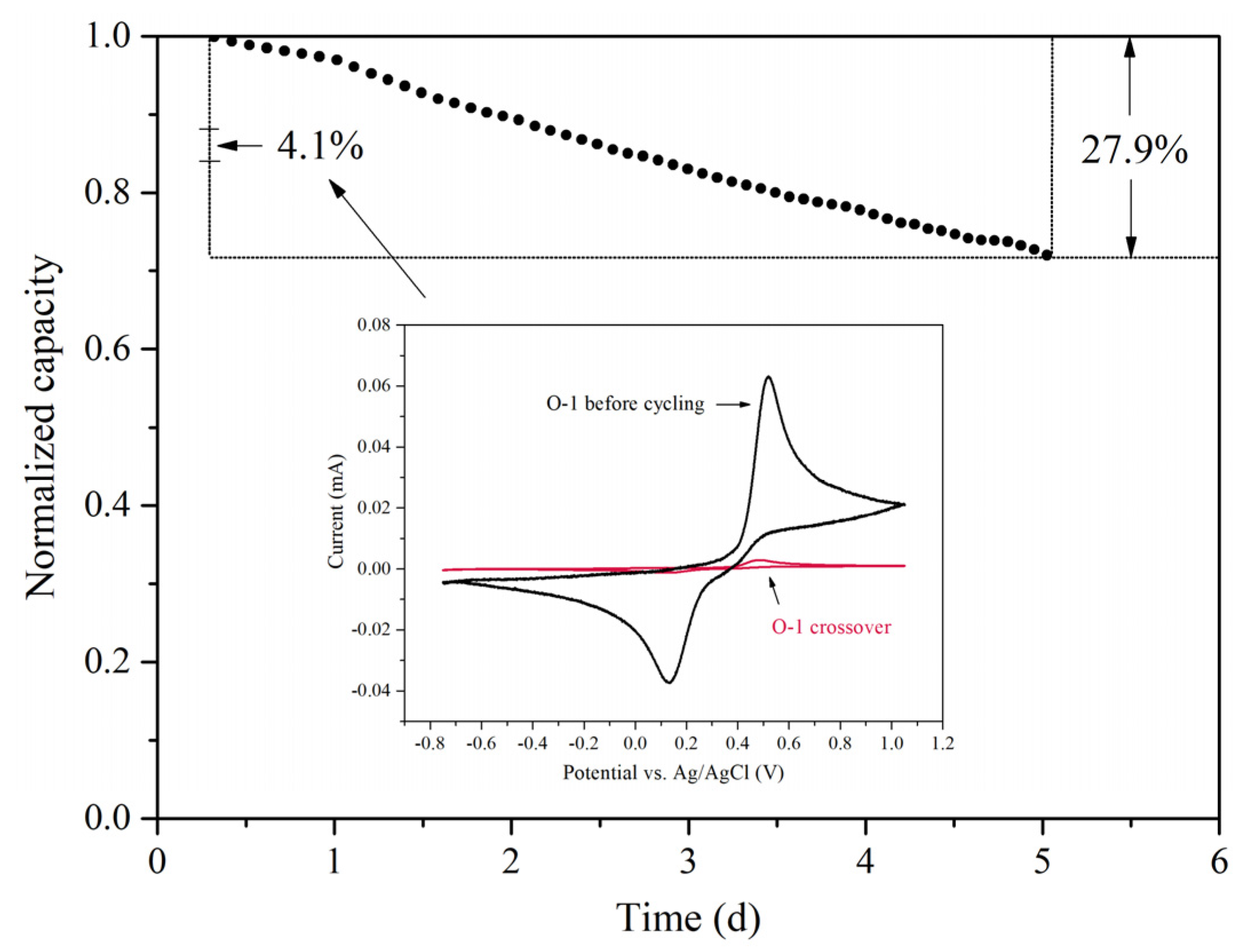
| 0.1 M O-1 in 1 M H2SO4 | 0.1 M O-1 in 1 M H2SO4 | 97% |
| 0.05 M O-5 in 1 M H2SO4 | 0.05 M O-5 in 1 M H2SO4 | 88% |
| 0.1 M asym-O-5 in 1 M H2SO4 | 0.1 M asym-O-5 in 1 M H2SO4 | 82% |
| Molecule | Capacity Decay Rate |
|---|---|
| O-1 | 2.9 to 7.3%/day |
| O-3 | 48.5 to 52.7%/day |
| O-5 | 0.78 to 1.1%/day |
| asym-O-5 | 0.45 to 1.8%/day |
| Reference | Electrolytes | Accessible Capacity |
|---|---|---|
| Li et al. [37] | 0.1 M BQDS a/0.1 M 2,7-AQDS in 1 M H2SO4 | 65% b |
| Zhang, Li and Chu [38] | 0.05 M BQDS/0.05 M ARS c in 1 M H2SO4 | 42% |
| Cao et al. [39] | 1 M BQDS/1 M 2,7-AQDS in 1 M H2SO4 | 26% b |
| Yang et al. [40] | 1 M BQDS/1 M 2,6-AQDS in 1 M H2SO4 | 35% |
Publisher’s Note: MDPI stays neutral with regard to jurisdictional claims in published maps and institutional affiliations. |
© 2021 by the authors. Licensee MDPI, Basel, Switzerland. This article is an open access article distributed under the terms and conditions of the Creative Commons Attribution (CC BY) license (https://creativecommons.org/licenses/by/4.0/).
Share and Cite
Yang, X.; Garcia, S.N.; Janoschka, T.; Kónya, D.; Hager, M.D.; Schubert, U.S. Novel, Stable Catholyte for Aqueous Organic Redox Flow Batteries: Symmetric Cell Study of Hydroquinones with High Accessible Capacity. Molecules 2021, 26, 3823. https://0-doi-org.brum.beds.ac.uk/10.3390/molecules26133823
Yang X, Garcia SN, Janoschka T, Kónya D, Hager MD, Schubert US. Novel, Stable Catholyte for Aqueous Organic Redox Flow Batteries: Symmetric Cell Study of Hydroquinones with High Accessible Capacity. Molecules. 2021; 26(13):3823. https://0-doi-org.brum.beds.ac.uk/10.3390/molecules26133823
Chicago/Turabian StyleYang, Xian, Sergio Navarro Garcia, Tobias Janoschka, Dénes Kónya, Martin D. Hager, and Ulrich S. Schubert. 2021. "Novel, Stable Catholyte for Aqueous Organic Redox Flow Batteries: Symmetric Cell Study of Hydroquinones with High Accessible Capacity" Molecules 26, no. 13: 3823. https://0-doi-org.brum.beds.ac.uk/10.3390/molecules26133823