A Mobility Management Using Follow-Me Cloud-Cloudlet in Fog-Computing-Based RANs for Smart Cities


Department of Computer Science and Information Engineering, National Taipei University, No. 151, University Rd., San Shia District, New Taipei City 23741, Taiwan
*
Author to whom correspondence should be addressed.
Sensors 2018, 18(2), 489; https://0-doi-org.brum.beds.ac.uk/10.3390/s18020489
Submission received: 30 December 2017
/
Revised: 3 February 2018
/
Accepted: 4 February 2018
/
Published: 6 February 2018
(This article belongs to the Special Issue The Architectures, Systems, and Applications of Internet of Things for Smart Cities)
Abstract
:Mobility management for supporting the location tracking and location-based service (LBS) is an important issue of smart city by providing the means for the smooth transportation of people and goods. The mobility is useful to contribute the innovation in both public and private transportation infrastructures for smart cities. With the assistance of edge/fog computing, this paper presents a fully new mobility management using the proposed follow-me cloud-cloudlet (FMCL) approach in fog-computing-based radio access networks (Fog-RANs) for smart cities. The proposed follow-me cloud-cloudlet approach is an integration strategy of follow-me cloud (FMC) and follow-me edge (FME) (or called cloudlet). A user equipment (UE) receives the data, transmitted from original cloud, into the original edge cloud before the handover operation. After the handover operation, an UE searches for a new cloud, called as a migrated cloud, and a new edge cloud, called as a migrated edge cloud near to UE, where the remaining data is migrated from the original cloud to the migrated cloud and all the remaining data are received in the new edge cloud. Existing FMC results do not have the property of the VM migration between cloudlets for the purpose of reducing the transmission latency, and existing FME results do not keep the property of the service migration between data centers for reducing the transmission latency. Our proposed FMCL approach can simultaneously keep the VM migration between cloudlets and service migration between data centers to significantly reduce the transmission latency. The new proposed mobility management using FMCL approach aims to reduce the total transmission time if some data packets are pre-scheduled and pre-stored into the cache of cloudlet if UE is switching from the previous Fog-RAN to the serving Fog-RAN. To illustrate the performance achievement, the mathematical analysis and simulation results are examined in terms of the total transmission time, the throughput, the probability of packet loss, and the number of control messages.
1. Introduction
Cloud computing driving centralization is shown to be useful to lower the marginal costs of system administration and operations, and edge computing is a new technique for an alternative to cloud computing by moving the computing resources and analysis works from the cloud to the edge, referred to as cloudlet or fog nodes. The fog nodes are placed in close proximity to mobile devices to deliver highly response cloud services [1]. It is highly challenge to integrate the edge/fog computing techniques into smart IoT infrastructure for the smart city. A fog-computing-based radio access network, namely F-RAN, had proposed in [2] to take the advantage of local radio signal processing, cooperative radio resource management, and distributed storing capabilities in edge devices to significantly overcome the disadvantage of cloud-RAN [2] of the heavy burden on front-haul communications and the large amount of radio signal processing operations in the centralized baseband unit pool of cloud-RAN [2]. In an F-RAN, edge node is endowed with caching capabilities and is controllable from a central cloud processor as in a C-RAN [3] to reduce the delivery latency. Mobility management allows UEs or goods to move access multiple points while keeping their data sessions. Distributed mobility management (DMM) is proposed in [4] to distribute the mobility anchors in the data plane in flattening the mobility network such that the mobility anchors are positioned closer to UE [4]. Distributed mobility management for future 5G networks is emerging as a valid framework taking into account the requirements for large traffic in the core and the rise of extremely dense wireless access networks [5]. This work aims to develop a new DMM with low delivery latency using proposed Follow-Me Cloud-Cloudlet (FMCL) concept in F-RANs for the smart city. There is a novel and similar result in [6] to present a Fog-supported smart city network architecture called Fog Computing Architecture Network (FOCAN). To decrease latency and improve energy provisioning and the efficiency of services among things with different capabilities, the applications running on things jointly compute, route, and communicate with one another through the smart city environment.
Before describing the proposed follow-me cloud-cloudlet approach, the Follow-Me Cloud (FMC) and Follow-Me Edge concepts are initially described. Follow-Me Cloud (FMC) concept is proposed in [7] to migrate user service by virtual machines (VMs) between data centers (DCs) to support the service migration and continuity due to UE mobility or load balancing. Many mobile applications are heavily based on data and processing capabilities from the cloud [8]. Fog computing paradigm arises to overcome high delay encountered when real time applications need the low latency to access data or things of smart cities. Cloudlets allow the low latency access to data and processing capabilities, which can be accomplished by dynamically building a local virtual machine (VM) near to UEs or goods. A fog computing-based architecture in [8] supports the handoff by the local VM migration. In addition, Mobile Edge Computing (MEC) research is proposed by realizing the Follow-Me Edge (FME) concept [9] to ensure that the service constantly follows the user and that the user is always serviced from the closest edge [9].
It is observed that Follow-Me Cloud (FMC) results do not have the property of the VM migration between cloudlets for the purpose of reducing the transmission latency. In contrast, Follow-Me Edge (FME) results do not keep the advantage of the service migration between data centers (DCs) for reducing the transmission latency. Efforts will be made to propose a follow-me cloud-cloudlet (FMCL) approach to keep the VM migration between cloudlets and service migration between data centers (DCs) to significantly reduce the transmission latency. With the assistance of edge/fog computing, this paper presents a mobility management using a proposed follow-me cloud-cloudlet (FMCL) approach in fog-computing-based radio access networks (Fog-RANs) for smart cites. The proposed follow-me cloud-cloudlet approach is an integration strategy of follow-me cloud and follow-me edge. The new proposed mobility management aims to reduce the total transmission time if some data packets are pre-scheduled and pre-stored into the cache of cloudlet if UE is switching from the previous Fog-RAN to the serving Fog-RAN. The main contributions of the proposed handover scheme with FMCL approach are summarized as follows.
- We had proposed follow-me cloud-cloudlet (FMCL) approach, which is a integration strategy of follow-me cloud and follow-me edge to inherit the properties of FMC and FME and explore the cooperation between clouds and cloudlets.
- We had proposed a new mobility management with using FMCL approach to reduce the total transmission time, upgrade the throughput, and reduce the probability of the packet loss. This is because that the transmission cooperation between the cloud and the cloudlet, while some packets can be pre-scheduled in the cache of cloudlets to reduce the total transmission time and upgrade the throughput. This is because that some pre-scheduled packets can be directly accessed from local cloudlet, and these pre-scheduled packets are avoided the long network transmission to further improve the probability of the packet loss.
The rest of the paper is organized as follows. Section 2 describes the related work and motivation. Section 3 describes the system model, problem formulation and basic idea of our proposed scheme. Section 4 describes our proposed handover protocol with FMCL. Section 5 provides the performance analysis, and the conclusion is finally given in Section 6.
2. Related Works
This section first describes related work in Section 2.1 and then provides the research motivation in Section 2.2.
2.1. Related Works
The work mainly discusses the mobility management in the fog-computing-based RANs for smart city. There are some results for fog-computing-based RANs and some related handover works in [1,2,3,10,11,12,13]. Satyanarayanan et al. [1] had explained the background, effect, and application of the edge computing. Edge computing is a new paradigm in which substantial computing and storage resources—variously referred to as cloudlets, micro datacenters, or fog nodes—are placed at the Internet’s edge in close proximity to mobile devices or sensors [1]. Peng et al. [2] proposed some issues and challenges about fog-computing-based radio access networks. Peng et al. [2] declared that the fog-RAN-based architecture is a model for the 5-G mobile networks. The main idea includes local radio signal processing, cooperative radio resource management and distributed storing capabilities in edge devices. Tandon et al. [3] considered a hybrid architecture, referred to as fog RAN (F-RAN), and presented an information-theoretic framework. The information-theoretic framework characterized the main trade-offs between performance of an F-RAN, in terms of the worst case of the delivery latency and resources of caching and fronthaul capacities. Liang et al. [10] developed the offloading services from the cloud to the edge of networks in fog-computing-based platform for offering the real-time data services to the nearby data terminal. Tandon et al. [11] defined the fog radio access network (Fog-RAN) architecture in [11]. Fog-RAN is an emerging wireless network architecture. This architecture utilizes the caching capabilities at the edge nodes to provide a low data access latency. Jalali et al. [12] studied about the energy consumption problem of nano data centers (nDCs) for the edge computing data center. Shin et al. [13] introduced the Fog-Radio Access Network (F-RAN) architecture to bring the efficient computing capability of the cloud to the network edge. By distributing computing-intensive tasks to multiple F-RAN nodes, F-RAN has the potential to meet the requirements of those ultra low-latency applications.
Some results of distributed mobility managements are reported in the literature. For instance, Balfaqih et al. [14] presented a network-based DMM solution. This work also developed an analytical model to evaluate the handover latency and the packet loss. To improve the performance during the handover, this work specifies a buffer technique at the new Mobile Anchor Access Router (nMAAR) for the packet buffering. Murtadha et al. [15] also designed a network-based fully distributed mobility management in flattened network architecture. In addition, some SDN-based mobility managements are recently reported in [16,17,18,19,20,21,22,23]. One interest result is a SDN-based handover result reported in [16,17]. Modares et al. [16] provides a useful survey on proxy mobile IPv6 hsndover. Raza et al. [17] proposed an inter-domain IP mobility solution with route optimization using the SDN-based proxy mobile IPv6. Wang et al. [18] focused on extending SDN paradigm to mobility handling in the Internet, and to propose the design, implementation and deployment of a software-defined IP mobility architecture. Yao et al. [19] proposed a dynamic switch migration scheme by dynamically adapting the the data flow to realize the load balance among multiple SDN controller. Garzon et al. [20] proposed an X2-based handover procedure in an SDN-based LTE architecture. Elgendi et al. [22] proposed a distributed mobility management (DMM) and a user rate-perceived (URP) algorithm over a 3-Tier SDN-based architecture. Carpio et al. [23] proposed a new load balancing solution in SDN-based data center networks.
Mobility management results using the concept of follow-me cloud (FMC) are recently studied in [7,24,25,26,27]. Aissioui et al. [24] proposed proxy MIPv6-based FMC in [24] by a inter-domain distributed mobility management. Nadembega et al. [25] proposed a mobility-based services migration prediction (MSMP) scheme by addressing the trade-off between the overhead and Quality of Experience (QoE). Ksentini et al. [26] further considered the trade-off by modeling the service migration issue by using a Markov Decision Process (MDP).
Mobility management results using the concept of follow-me edge (FME) is studided in [9]. Taleb et al. [9] realized the FME concept by enforcing an autonomic creation of Mobile Edge Computing (MEC) service to allow the data access with the optimum QoE and the reduced latency. To realize the FME, the Edge Orchestrator (EO) of the mobile network operators (MNOs) needs to update the resource information and the user location information.
Some novel results of cloud and fog services to vehicular networks had developed [28,29]. Shojafar et al. [28] proposed an energy-efficient adaptive resource management for real-time vehicular cloud services. Naranjo et al. [29] proposed an energy-efficient adaptive scheduler for Vehicular Fog Computing (VFC) that operates at the edge of a vehicular network. Some results of 5G mobile networks with caching are provided [30,31,32,33]. Zakrzewska et al. [30] investigated the key challenges and current trends of 5G mobile networks.
2.2. Motivation
As mentioned in Section 2.1, two kinds of mobility managements are reported; one is the mobility managements using the concept of follow-me cloud (FMC) [7,24,25,26,27] and another one is the mobility management using the concept of follow-me edge/cloudlet (FME) [9]. The main motivation of this work is attempted to propose a new mobility management with the integration of the concepts of follow-me cloud (FMC) [7,24,25,26,27] and the follow-me edge/cloudlet (FME) [9], which is called as follow-me cloud-cloudlet (FMCL) approach in this paper. Existing FMC results do not own the novel property of the VM migration between cloudlets for the purpose of reducing the transmission latency. All existing (FME) results do not keep the advantage of the service migration between data centers (DCs) for reducing the transmission latency. Efforts will be made to propose a follow-me cloud-cloudlet (FMCL) approach to keep the VM migration between cloudlets and service migration between data centers (DCs) to significantly reduce the transmission latency. Thus, this work is to propose a new mobility management using the FMCL approach for the smart cities. One interested capability of fog-computing-based RAN architecture is that F-AP (fog-computing-based access point) of F-RAN contains the local cache functionality. Consequently, the new mobility management with the FMCL approach can inherit the advantage of the service migration from follow-me cloud (FMC) [7,24,25,26,27] and can explore and additionally keep the data locality property from the local cache functionality from the follow-me edge (FME) [9].
Consequently, one of the benefits is that the optimal shortest route can be re-calculated and re-constructed from the new service migrated data center to significantly reduce the network transmission latency. Another one is that all received packets can be pre-scheduled to the cache of edge/cloudlet to keep this data locality property of cache to improve the throughput and reduce the packet loss rate.
3. Preliminaries
This section describes the system model, the problem formulation, and basic idea in Section 3.1, Section 3.2 and Section 3.3.
3.1. System Architecture
The fog-computing-based RAN system architecture evolution from cloud-radio access network (C-RAN) [1,2,3] is shown in Figure 1. To overcome the disadvantages of C-RANs with the fronthaul constraints, the user and control planes are decoupled in such networks and the high power nodes (HPNs) are mainly used to provide seamless coverage and execute the functions of the control plane, while remote radio heads (RRHs) are deployed to provide high-speed data rate for packet traffic transmission in the user plane. The fronthaul portion of a C-RAN telecommunications architecture comprising the intermediate links between the centralized radio controllers and remote radio heads (RRHs) at the edge of a cellular network [1]. One main difference between C-RANs and F-RANs is that the centralized control function is shifted from the BBU pool in C-RANs to the HPN in F-RANs [2]. To incorporate fog computing in edge devices, the traditional RRH is evolved to the fog-computing-based access point (F-AP) by being equipped with a certain caching, CRSP, and CRRM capabilities [2]. The main difference between C-RANs and F-RANs is that the centralized control function is shifted from the BBU pool in C-RANs to the HPN in F-RANs [2].
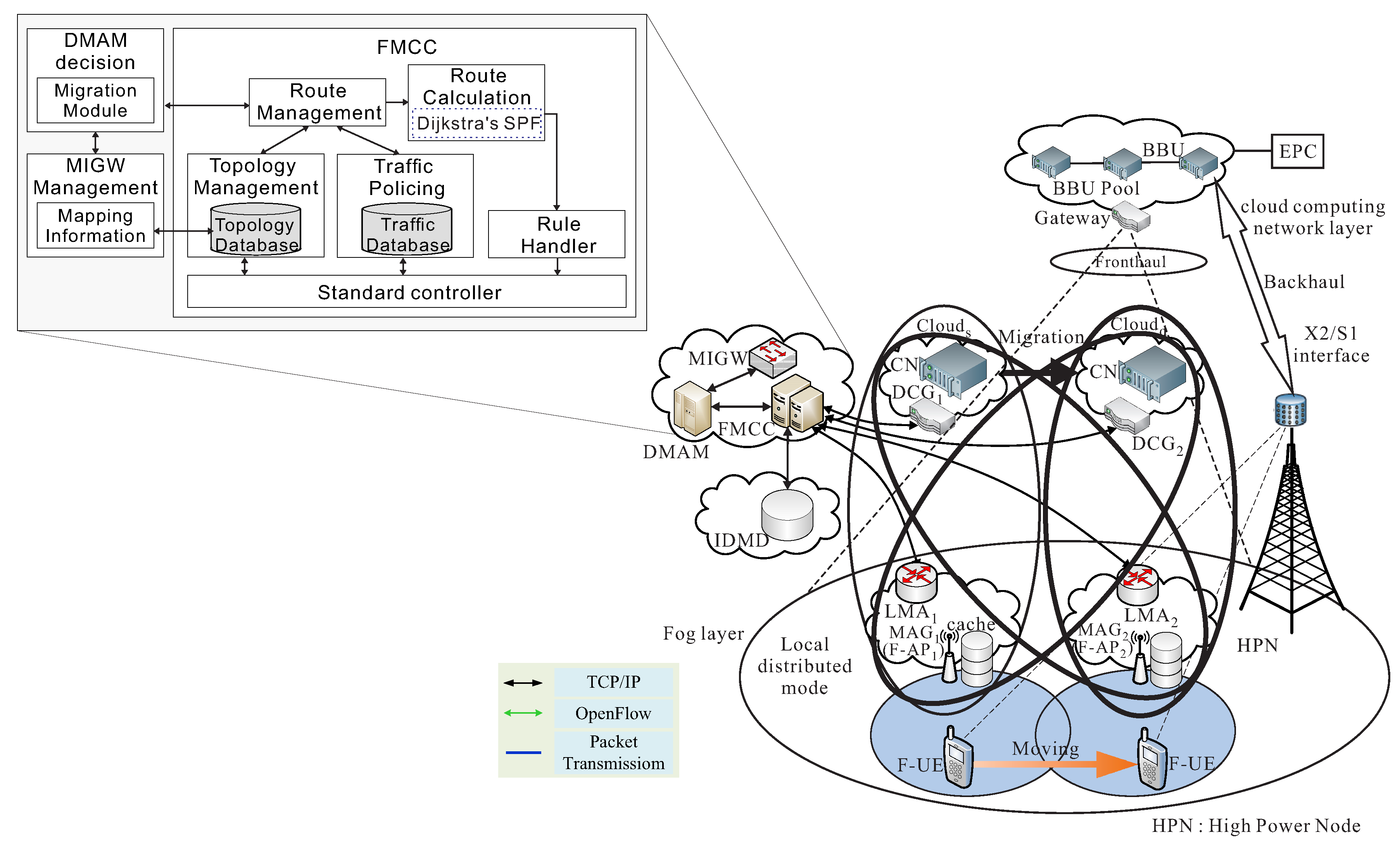
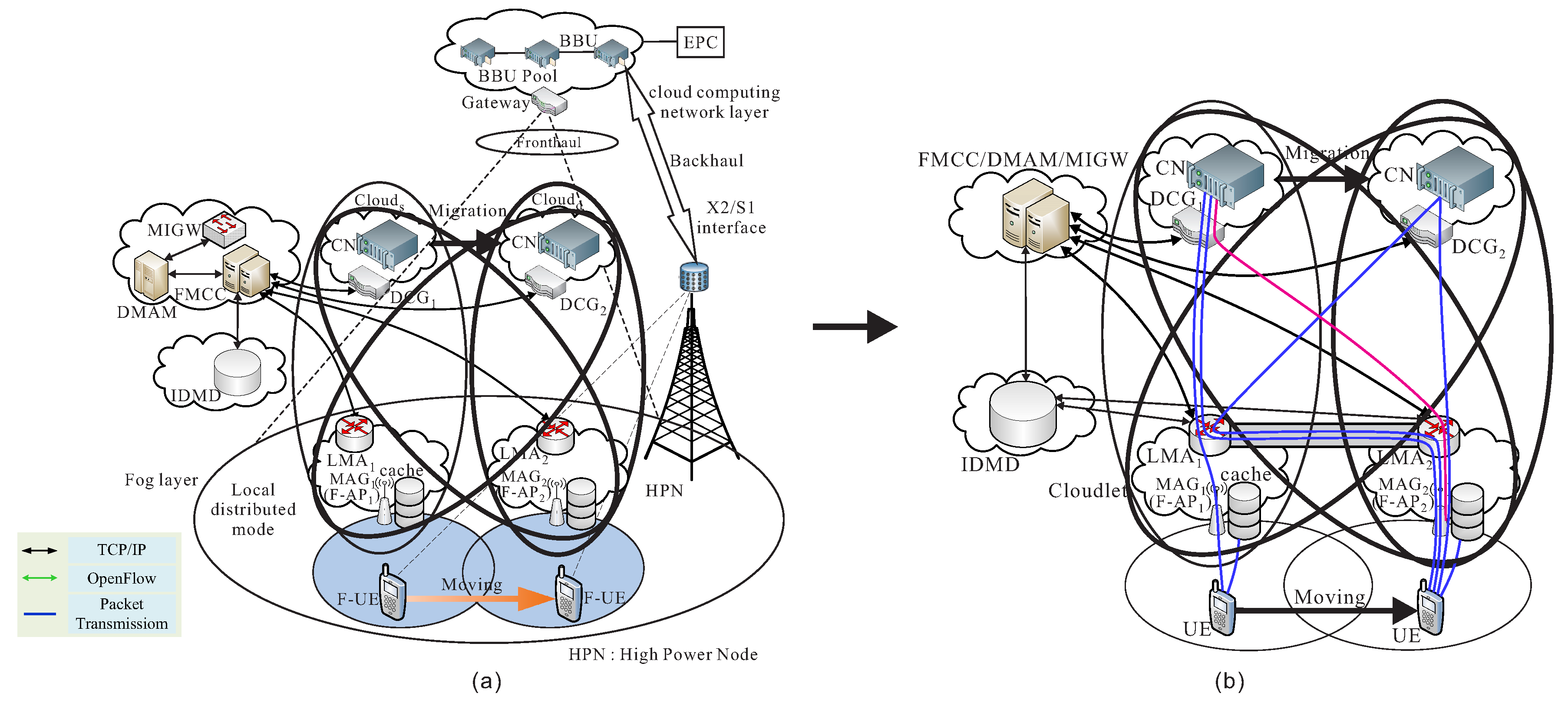
As shown in Figure 2a, the system architecture for our proposed follow-me cloud-cloudlet is modified from the system architecture of mobility using follow-me cloud approach from Aissioui et al.’s work in [24], and its simplified architecture is given in Figure 2b. Consequently, our system architecture also contains the follow-me cloud controller (FMCC), decision making application module (DMAM), mapping information gateway (MIGW), inter domain mobility database (IDMD), and local mobility anchor (LMA) [24]. The service migration of follow-me cloud approach [24] is also provided and reviewed as follows. When an UE switches to a different region, FMCC then decides to initiate a service migration from the current serving data center to the new serving data center, and also initiate a handover procedure and re-calculate the shortest route from the new serving data center gateway (DCG) to the next LMA of the new serving F-AP. In our follow-me cloud-cloudlet approach, FMCC also pre-sends some packets to the cache of the new serving F-AP to reduce the total data transmission time.
In the paper, we propose a new mobility management using the follow-me cloud-cloudlet (FMCL) approach for the smart city. This main purpose of FMCL approach is to reduce the total transmission time and the packet loss rate, under a handover to a different area.
The network architecture of the fog-computing-based RANs (or called as F-RANs) contains that there is a cloud set , where is the s-th serving data center or the s-th serving cloud, and cloudlet set , where is the s-th serving cloudlet, then a cloud-cloudlet () set is defined as . In general, we assumed that an in the area with moves to a different area with . Let represent as the packet transmission from cloud to cloudlet during our mobility management using the cooperation transmission of cloud-cloudlet.
When the moves from a previous area with to a different area with , the current serving is performed the service migration operation to the new serving . The MAG of sends out a proxy binding update (PBU), , to the inter domain mobility database (IDMD), where TIM (Traffic Information Message) is utilized to keep the receiving packet status of all packet transmissions during the handover procedure. The IDMD then creates an entry in its Binding Cache Entry (BCE) table. The new record of the BCE table is . After the IDMD receiving , the IDMD sends a migration-request message to the FMCC. The migration-request message contains the ID of UE, the allocated prefix, the new allocated LMA, and the cache data in . After the FMCC obtaining the message, the FMCC concurrently finds the optimal transmission path between the new Data Center Gateway (DCG) of and new allocated LMA of . When the FMCC determines the optimal path from to , the FMCC sends out to the new to switch to the new path.
3.2. Problem Formulation
In the work, we attempted to develop a follow-me cloud-cloudlet approach for the mobility management. The main purpose is to reduce the transmission time during the handover by increasing the cache hit rate. As defined previously, The proposed follow-me cloud-cloudlet architecture contains a cloud-cloudlet () set as , where , , , and are determined by FMCC during the handover operation. When FMCC decides the , we try to pre-cache of the of the required data packets. Let be denoted as the packet quantity existed in cache of the fog-computing-based RAN architecture. A data file F considered in this work is divided into n packets, , where n is the total packet number of F. In our mobility protocol design, the total data transmission time when switching to different access point is + + + , where is the time cost of the follow me () phase, is the time cost of the follow me cloudlet () phase is the time cost of the follow me cloud () phase, and is the time cost of the follow me cloud-cloudlet () phase (as described below). The problem is formulated to minimize the total data transmission time as:
where , . Time and denoted that the data transmission time of packet and is directly accessed from cache of clodlets and , and denoted that the data transmission time of packet and must be transmitted from data center of clouds and , respectively.
3.3. Basic Idea
This basic idea of the mobility management is to propose a cooperation strategy of cloud and cloudlet to reduce the transmission time and the packet loss rate.
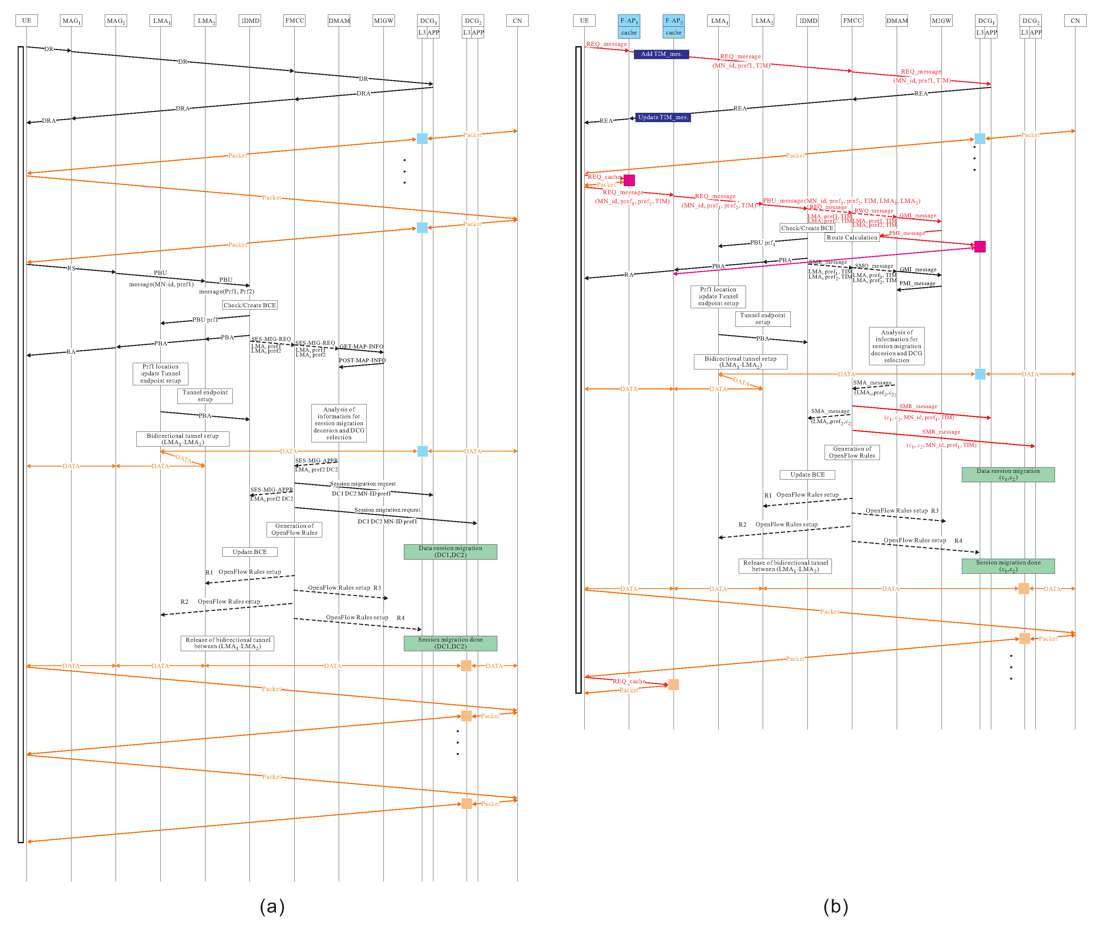
Based on the proxy MIPv6-based FMC result of [24], all data packets are tunneled between MAG (Mobile Access Gateway) and LMA (Local Mobility Anchor) to keep the high connectivity property. As mentioned before, a cloud-cloudlet () set is . When attached to a different MAG, four kinds of cooperation of cloud-cloudlet (), cloud-cloudlet (), cloud-cloudlet (), and cloud-cloudlet () are defined below. The comparison of of proxy MIPv6-based FMC proposed by Aissioui et al. [24] and our the handover protocol using follow me cloud-cloudlet is illustrated in Figure 3.
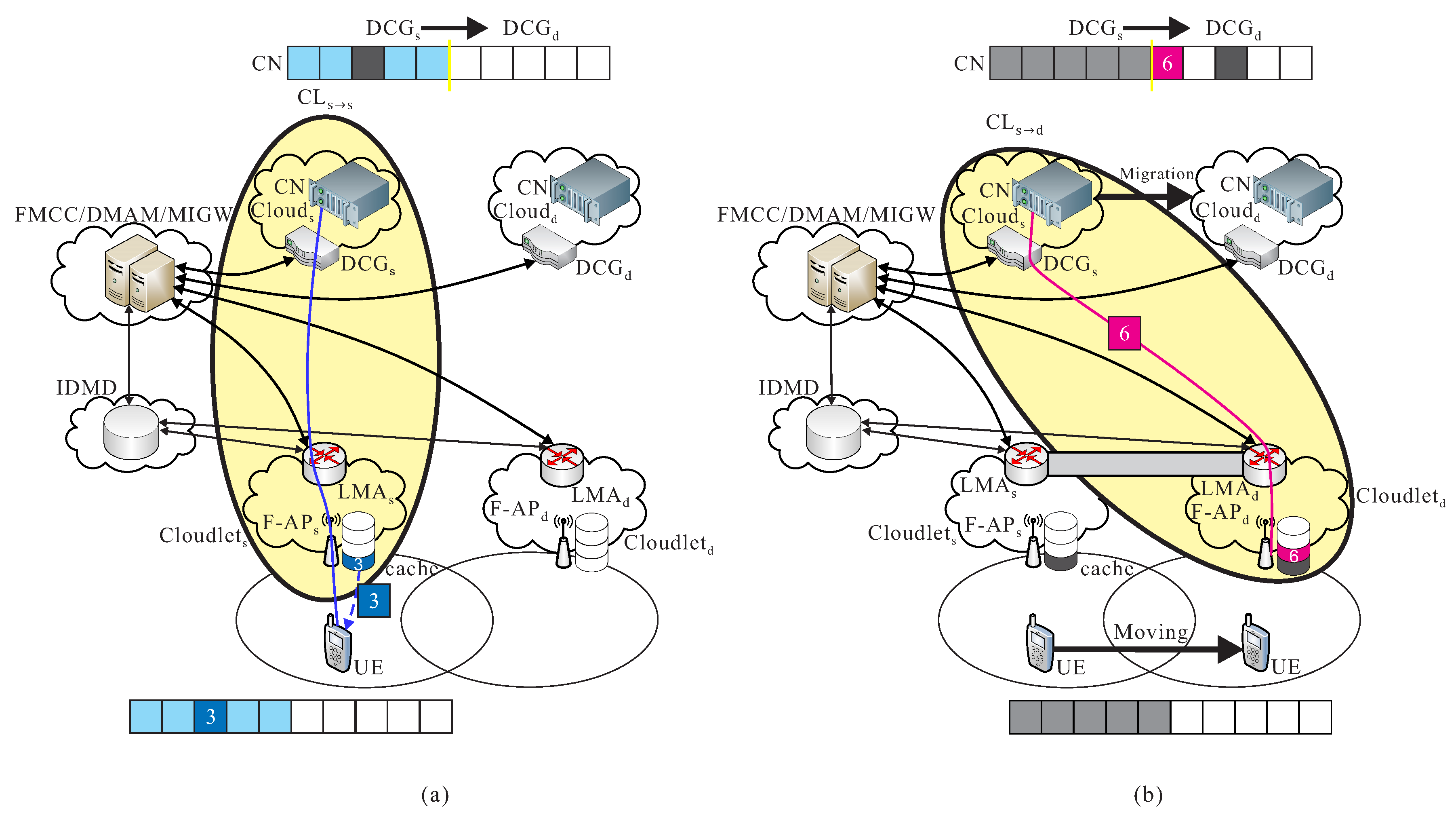
Cooperation of cloud-cloudlet : Before the handover event of UE, assumed that and are the current serving cloud and cloudlet of the current serving F-RAN. Packets from the CN in data center of are transmitted to UE through F-AP. For instance as shown in Figure 4a, the cooperation of cloud-cloudlet is provided.
Cooperation of cloud-cloudlet : When UE moves to a different region, and initiate the handover procedure, some packets are still transmitted from the current serving data center of to the new serving cloudlet if the data migration procedure is still not initiated. For instance as shown in Figure 4b, the cooperation of cloud-cloudlet is provided.
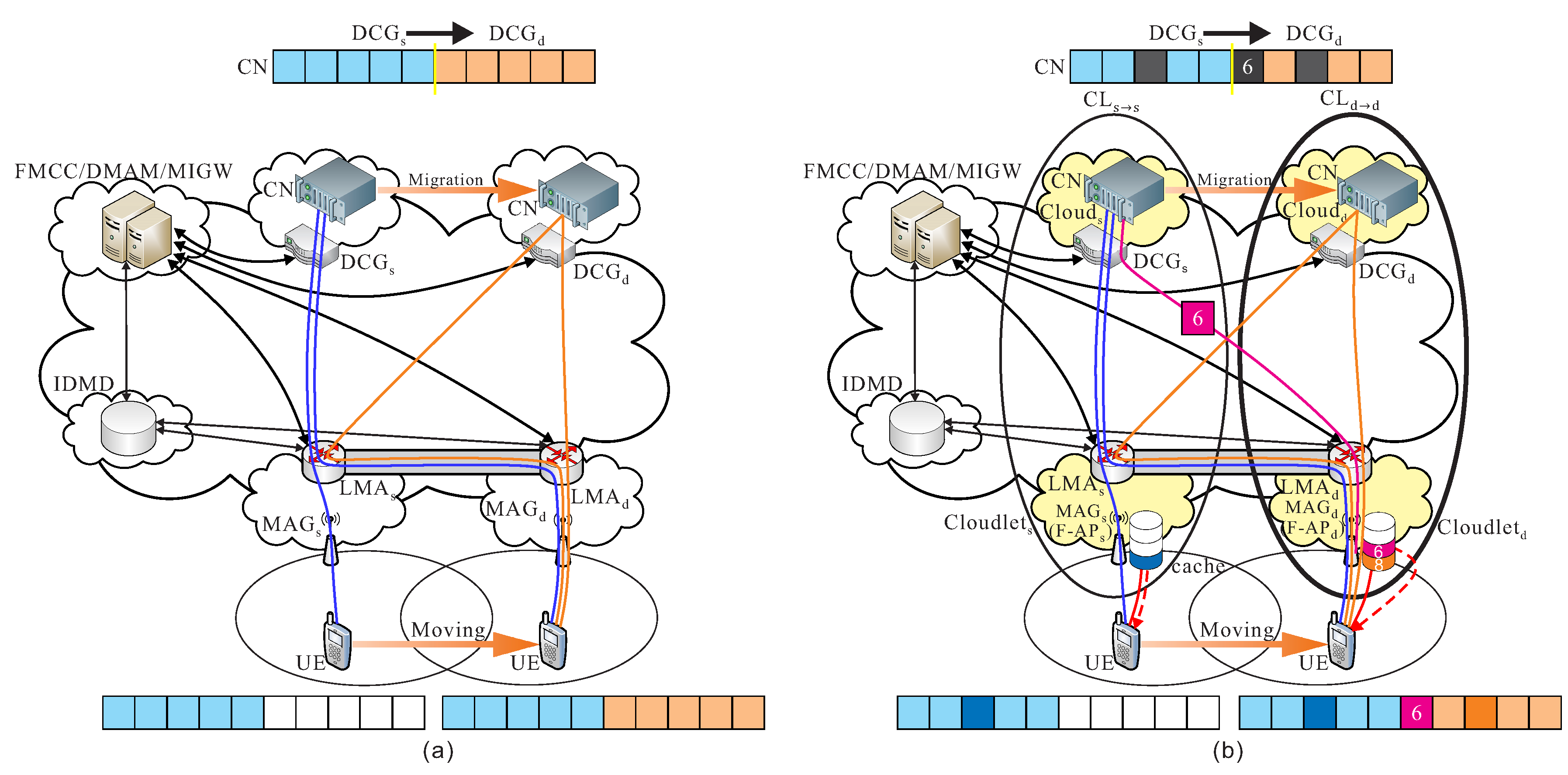
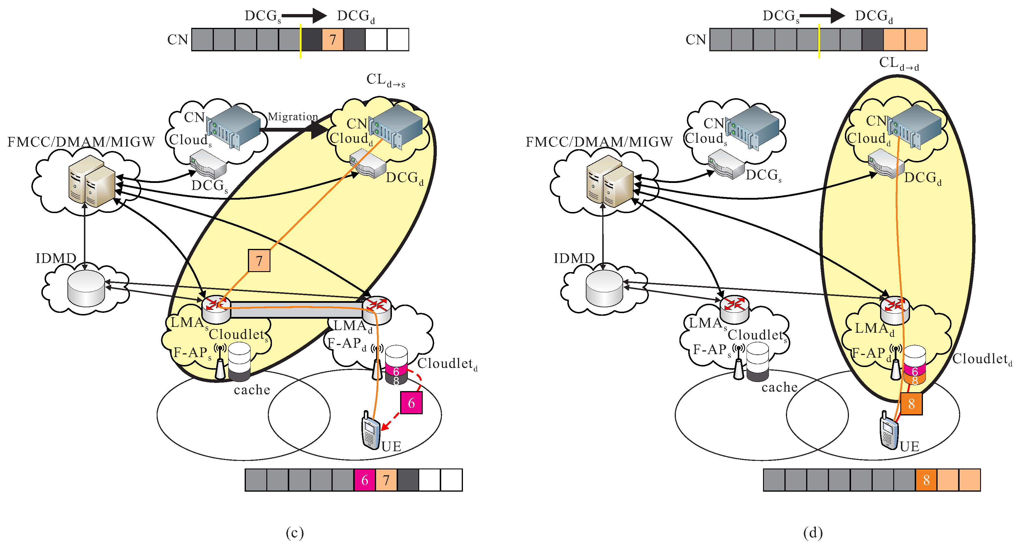
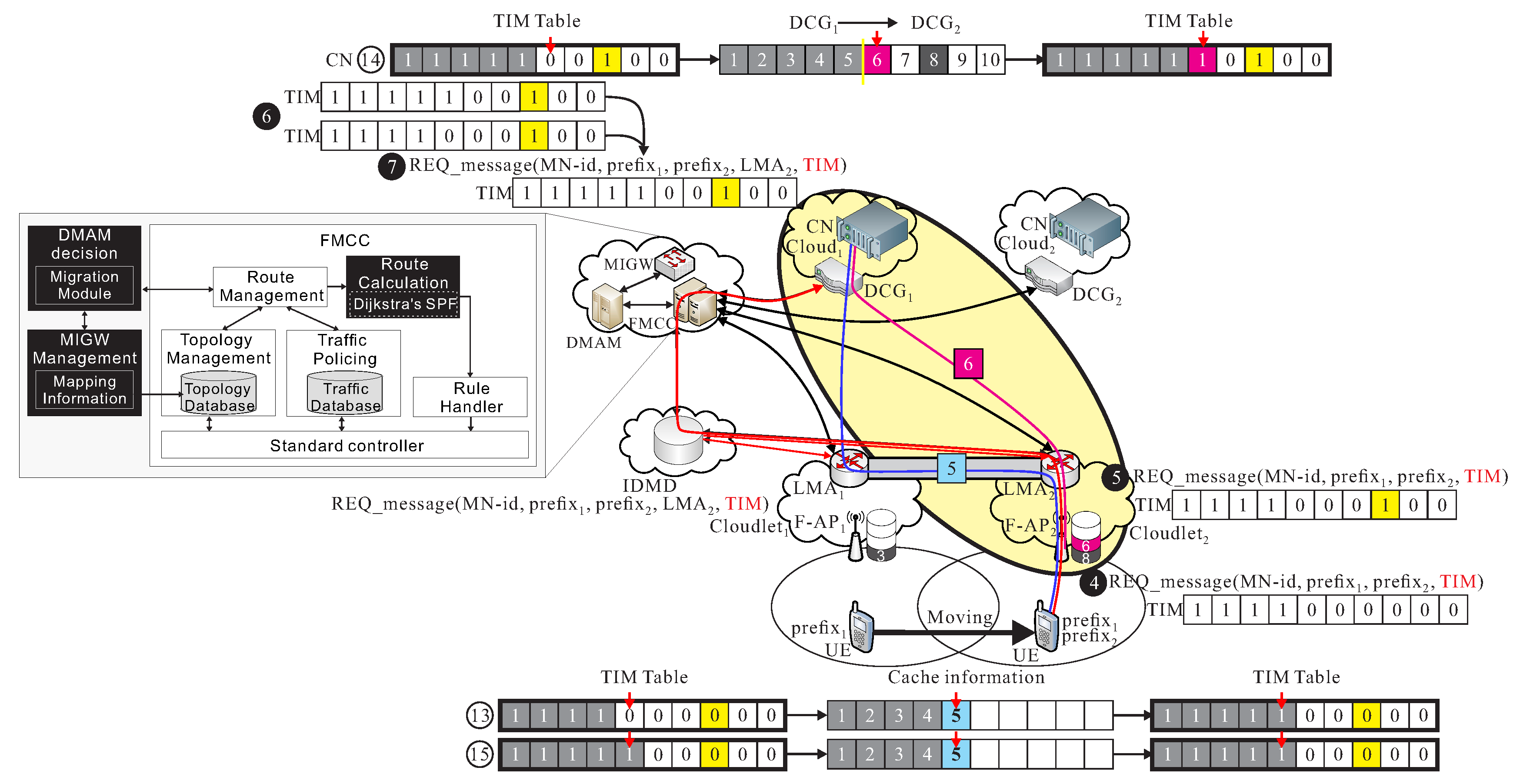
Cooperation of cloud-cloudlet : After UE is moving to a different region, a data migration operation is executed from to , it also means that CN is migrated from to . Packets are then transmitted from the new serving data center of to the previous cloudlet , and then be re-forward to the new cloudlet to UE, before the new route path from to is not re-calculated in FMCC. For instance as shown in Figure 5a, the cooperation of cloud-cloudlet is provided.
Cooperation of cloud-cloudlet : After the new route path is re-routed from the new serving data center of to the new cloudlet which is determined by FMCC, packets are transmitted from to UE through F-AP of by using the new re-calculated route path. As shown in Figure 5b, an example of the cooperation of cloud-cloudlet is given.
4. Mobility Management Using Follow-Me Cloud-Cloudlet Approach
In the section, mobility management using proposed follow-me cloud-cloudlet approach in F-RAN for smart cities is given. As mentioned in Section 3.3, four kinds of cooperation of cloud-cloudlet are defined, our mobility management is divided into four phases to implement these four cooperation of cloud-cloudlet, respectively.
- Follow me phase: This phase is to implement the cooperation of cloud-cloudlet . Before the handover event of UE, assumed that and are the current serving cloud and cloudlet of the current serving F-RAN. Packets from the CN in data center of are transmitted to UE through F-AP.
- Follow me cloudlet phase: This phase is to implement the cooperation of cloud-cloudlet . When UE moves to a different region, and initiate the handover procedure, some packets are still transmitted from the current serving data center of to the new serving cloudlet if the data migration procedure is still not initiated.
- Follow me cloud phase: This phase is to implement the cooperation of cloud-cloudlet . After UE is moving to a different region, a data migration operation is executed from to , it also means that CN is migrated from to . Packets are then transmitted from the new serving data center of to the previous cloudlet , and then be re-forward to the new cloudlet to UE, before the new route path from to is not re-calculated in FMCC.
- Follow me cloud-cloudlet phase: The phase is to implement the cooperation of cloud-cloudlet . After the new route path is re-routed from the new serving data center of to the new cloudlet which is determined by FMCC, packets are transmitted from to UE through F-AP of by using the new re-calculated route path.
The detailed operations of the mobility management using proposed follow-me cloud-cloudlet approach in F-RAN are described as follows. Message flow diagrams of PMIPv6-based FMC approach and our proposed mobility management using FMCL approach, are illustrated in Figure 6.
4.1. Follow-Me Phase
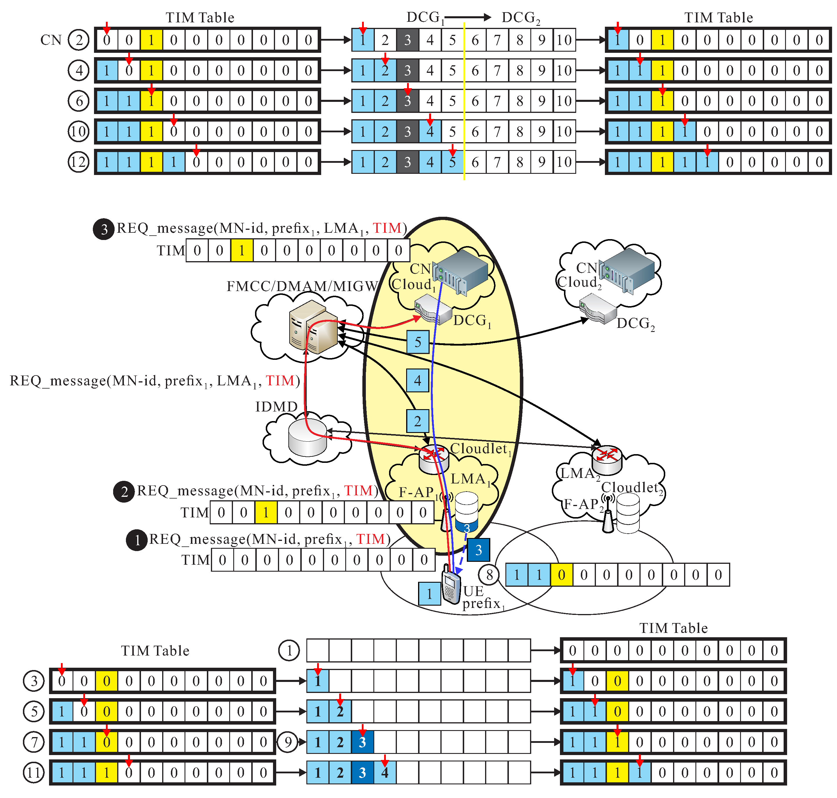
This phase mainly implements the cooperation of cloud-cloudlet . Let or simplified as is denoted as a data transmission request message, where is UE’s ID, and are UE’s the prefix of the network address, and is the traffic indication map to indicate the packet receiving status.
Assumed that a data file is divided into n packets, . of is n-bit map, , if is equal to 1 then k-th packet is received by UE, and if is equal to 0, then k-th packet is not received by UE, where . Before the handover event of UE, assume that and are the current serving cloud and cloudlet of the current serving F-RAN. Packets from the CN in data center of are transmitted or not, which is dependent on the which is extracted from received , to UE through F-AP.
The message is initiated from UE and forward the through the serving LMA to the inter domain mobility database (IDMD). After IDMD receiving , a registration operation is executed in IDMD to create an entry in IDMD table as . The is forward to follow me cloud controller (FMCC). if FMCC receives the message, is also forward to to the serving data center (DC) of cloud . DC of extracts from received . DC examines , if the value of of is 0, then DC transmits k-packet toward through . UE also keeps a same . changes the value of from 0 to 1 if receives k-th packet from the serving DC. Then, . The detailed procedure is given below.
- S1.
- initiates , to F-AP, where , and =0, ,
- S2.
- The reaches to F-AP of . The F-AP checks if k-th packets is already existed in cache of F-AP, then update of accordingly, where . The updated is re-inserted into the updated , and then forward the new to IDMD and FMCC.
- S3.
- DC of extracts from received . Before the handover event, DC repeatedly examines , if the value of , for , of is 0, then serving DC transmits k-packet toward through . UE also keeps , and concurrently updates the value of from 0 to 1 if successfully receives k-th packet.
- S4.
- If the handover decision of UE is made by switching from F_AP to F_AP, then go to the follow-me cloudlet phase. Then, .
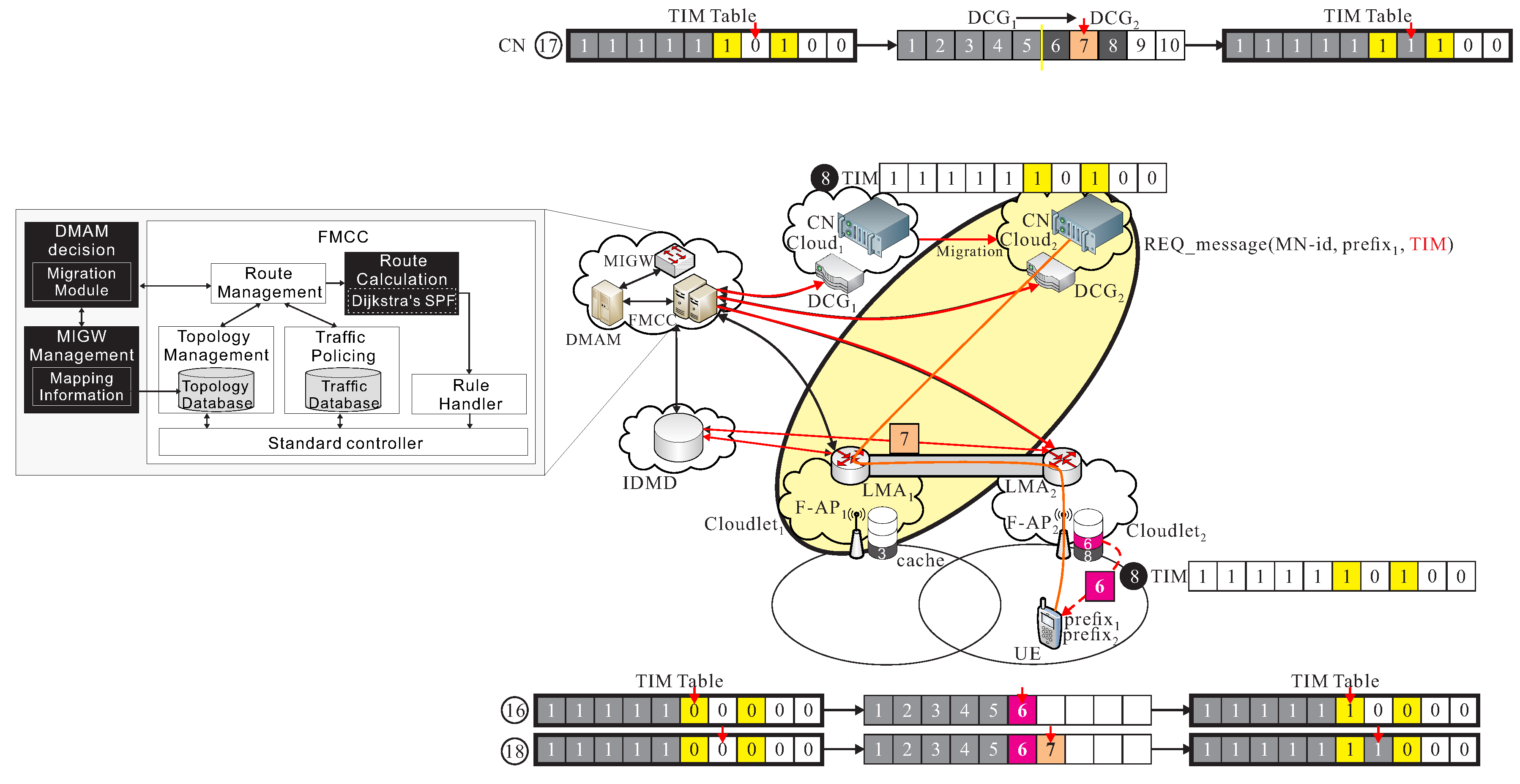
As shown in Figure 7, sends out with updated by F through IDMD to FMCC, because that 3-th packet existed is in cache of . Finally, packets 1, 2, 3, and 4 are successfully received by UE, but packets 1, 2, 4, and 5 are transmitted from . Therefore, = (1, 1, 1, 1, 0, 0, 0, 0, 0, 0).
4.2. Follow-Me Cloudlet Phase
This phase implements the cooperation of cloud-cloudlet . After performing follow-me phase, assume that we have . When UE moves to a different region, and initiate the handover procedure, un-transmitted packets are still transmitted from the current serving data center of to the new serving cloudlet , note that the data migration procedure is still not initiated, such that we may have , where . That is, there are pre-transmitted packets. Some of these bits of TIM can be set to be 1 if these corresponding packets are already exited in cache of .
The detailed procedure is given.
- S1.
- When is moving to the new region with F-AP of , the initiates a request message, namely , if the TIM message indicates that m packets are already successfully received by UE after executing the follow-me phase. The also informs FMCC to carry the handover information with the report of the remaining un-received packets. The F-AP also checks if k-th packets is already existed in cache of F-APs, then let of , where . The updated is re-inserted into the updated and forward to IDMD and FMCC.
- S2.
- MAG in receives the from F-AP, MAG initiates a proxy binding update (PBU), or to LMA and forward it to IDMD. After IDMD receiving , IDMD updates the binding cache entry (BCE) table, , . The IDMD generates the proxy binding acknowledgement (PBA), to two LMA of the and .
- S3.
- FMCC receives the session-migration-request message, from IDMD if IDMD receives updated . FMCC sends to decision making application module (DMAM). DMAM is activated by the request from FMCC. DMAM is responsible of making the decision of the data migration to search for an optimal cloud .
- S4.
- DMAM analyzes the user information, in addition to the mapping information of and by generating get-mapping-information message, , to mapping information gateway (MIGW). MIGW then initiates a post-mapping-information message, , to DMAM.
- S5.
- After DC of cloud verifying the received TIM message, the DC of cloud randomly pre-transmits some -th un-transmitted packets, where and . The corresponding bits are set 1, for , in the TIM message if the packet are successfully pre-transmitted toward to cloudlet and kept the pre-transmitted packets in cache of . This pre-transmission operation is done until the new route path is determined in follow-me cloud-cloudlet phase. Finally, some of these bits of TIM can be set to be 1 if these corresponding packets are already exited in cache of .
- S6.
- Finally, FMCC notifies and about the current user’s information containing current message, the location information through the analysis of DMAM and MIGW.
As shown in Figure 8, moves from to and transmits a new to , where TIM is (1, 1, 1, 1, 0, 0, 0, 0, 0, 0). This phase allows 5-th packet can be re-forward from to , and allows 6-th packet can be pre-transmitted from to , so becomes (1, 1, 1, 1, 1, 0, 0, 0, 0, 0), but 6-th packet is pre-transmitted, but, finally = (1, 1, 1, 1, 1, 0, 0, 1, 0, 0), since we assumed 7-th packet is already existed in cache of .
4.3. Follow-Me Cloud Phase
This phase mainly implements the cooperation of cloud-cloudlet . After UE is moving to a different region, a data migration operation is executed from to , it also means that CN is migrated from to . After performing follow-me cloudlet phase, assume that we have . Thus, packets are then transmitted from the new serving data center of to the previous cloudlet , and then be re-forward to the new cloudlet to UE, before the new route path from to is not re-calculated in FMCC. Then, we have , where . That is, there are packets are transmitted in this phase. The detailed procedure is given.
- S1.
- The FMCC, DMAM and MIGW decide to execute the data migration procedure
- S2.
- DMAM sends a session-migration-approved message, , to FMCC. DMAM instructs FMCC to generate the essential traffic of the control plane by ensuring the seamless service migration procedure below. After FMCC receiving from DMAM, it enables OpenFlow rules of the FMCC. FMCC sends out session-migration-request message, to notify and to execute the data migration. Based on information of TIM message, all un-transmitted packets, for all and , including TIM message are migrated from DC of to DC of .
- S3.
- After DC of cloud verifying the received TIM message, the DC of cloud randomly pre-transmits some -th un-transmitted packets, where and . The corresponding bits are set 1, for , in the TIM message if the packet are successfully pre-transmit toward to cloudlet and keep the pre-transmitted packets in cache of . This pre-transmission operation is done until the new route path is determined in follow-me cloud-cloudlet phase.
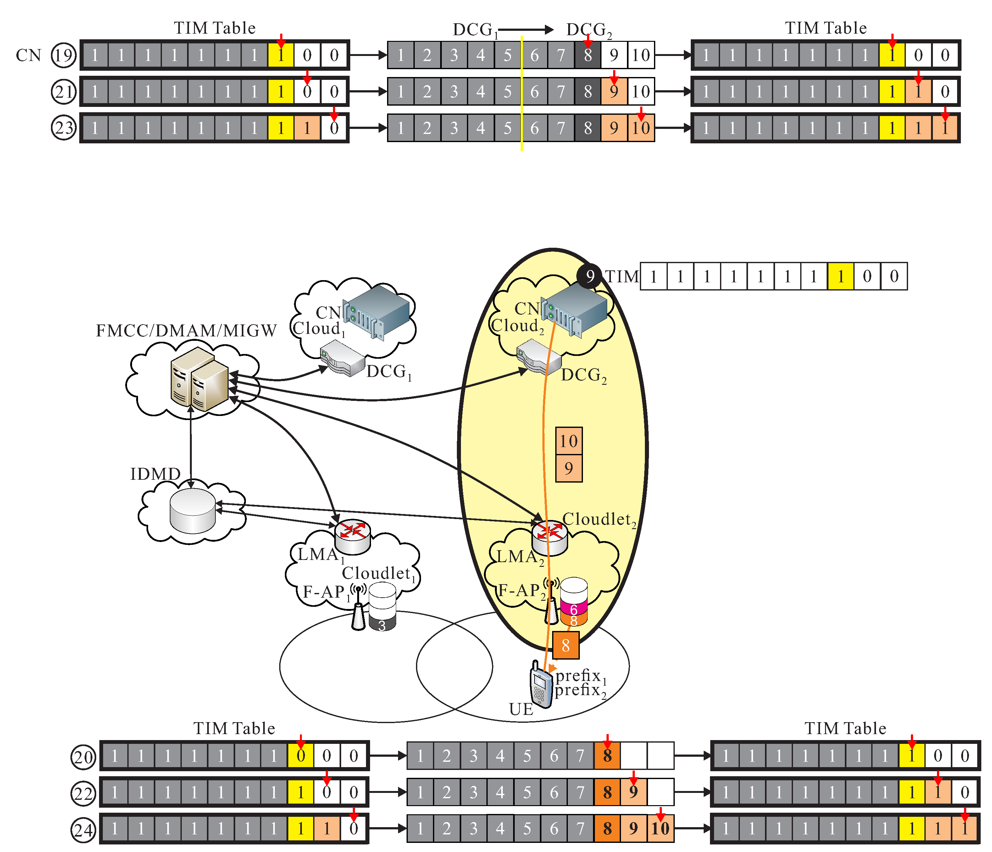
As shown in Figure 9, 8-th packet is transmitted if TIM = (1, 1, 1, 1, 1, 1, 0, 1, 0, 0), and , from the last phase. Finally, TIM = (1, 1, 1, 1, 1, 1, 1, 1, 0, 0), and the above operation is done before the new route path from to .
4.4. Follow-Me Cloud-Cloudlet Phase
The phase mainly implements the cooperation of cloud-cloudlet . We now have Then, we have , where . After the new route path is re-routed from the new serving data center of to the new cloudlet which is determined by FMCC, un-transmitted packets are transmitted from to UE through F-AP of by using the new re-calculated route path. The detailed procedure is given.
- S1.
- When a new route path from DC of to DC of is re-calculated in route calculation module of FMCC, FMCC generates the OpenFlow flow-mod message to DCG of to LMA of , the new re-calculated route from DCG of to LMA of is then constructed.
- S2.
- All k-th un-transmitted packets from the final TIM message, for all if and are sequentially transmitted by using the new re-calculated route from DCG of to LMA of . Finally, all packets are successfully received by UE such that .
As shown in Figure 10, since = (1, 1, 1, 1, 1, 1, 1, 1, 0, 0), then 9-th and 10-th packets are transmitted from CN of and finally all packets are received, where = (1, 1, 1, 1, 1, 1, 1, 1, 1, 1).
5. Performance Analysis
Our paper presents a mobility management using FMCL approach F-RAN for smart cities. A mathematical analysis and simulation results are provided. Our paper presents a mobility management using FMCL approach. To evaluate our handover protocol (proposed scheme with FMCL), and Aissioui et al.’s. proxy MIPv6-based FMC (PMIPv6 with FMC) [24], all these protocols are mainly implemented using the Ryu and Mininet as illustrated in Table 1. Ryu [35] is a component-based software defined networking framework. Ryu provides software components with well defined API that make it easy for developers to create new network management and control applications. Ryu supports various protocols for managing network devices, such as OpenFlow, Netconf, OF-config, etc. About OpenFlow, Ryu supports fully 1.0, 1.2, 1.3, 1.4, 1.5 and Nicira Extensions. All of the code is freely available under the Apache 2.0 license [35]. Mininet [36] creates a realistic virtual network, running real kernel, switch and application code, on a single machine (VM, cloud or native). Mininet is a way to develop, share, and experiment with OpenFlow and Software-Defined Networking systems [36]. In our simulation, we built two two computers; one is installed a SDN controller, Ryu 4.1 (IP: 172.24.4.2); and another one is installed OpenFlow-based Software-Defined Networking systems by mininet (IP: 172.24.24.2) under the same IP domain.
Before describing the performance metrics, the mathematical analysis of the total transmission time and space cost is described.
Theorem 1.
The total transmission time of the proposed mobility management with FMCL approach is , where the cache hit rates of packets in caches of and are α and β, respectively.
Proof.
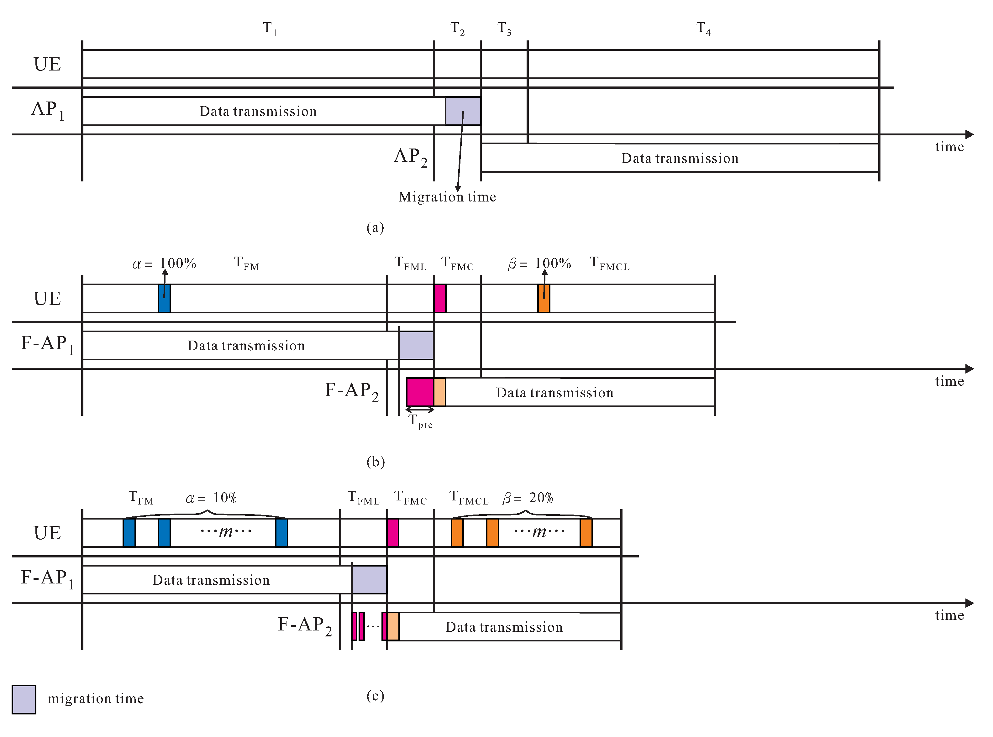
Following notations in Section 4, a data file is divided into n packets, , where . The total transmission time is divided into four phases, , , , and as illustrated in Figure 11a–c, where is the time cost of performing follow-me phase, is the time cost of performing follow-me cloudlet phase, denotes as the time cost of performing follow-me cloud phase, and is the time cost of executing follow-me cloud-cloudlet phase. , where the cache hit rate of packets in cache of is , and and denote as the unit transmission time of packet transmitted from cloudlet or data center , which is depended on packet ∈ or , where . The data migration time is , where as the unit time of packet migrated from to , where . , where is the unit transmission time of packet transmitted from data center to cloudlet , where . , where is the unit transmission time of packet transmitted from data center to cloudlet , where . , where the cache hit rate of packets in cache of is , and and denote as the unit transmission time of packet transmitted from cloudlet or data center , which is depended on packet ∈ or , where . Consequently, the total transmission time . ☐
Theorem 2.
The space cost of the proposed mobility management with FMCL approach is + , where , , and denote as the space size of packet .
Proof.
If , and , as illustrated in Figure 11c, the space size of is before the handover and the space size of is after the handover, the total space size is + . ☐
Example is offered in Figure 11a–c, the time and space costs of proxy MIPv6-based FMC is given in Figure 11a. The time and space costs of our proposal scheme with FMCL are given in Figure 11b–c if and if and , respectively. The performance metrics to be observed are:
- Total transmission time is the time cost of all n packets are successfully received by and transmitted from during the handover from F_AP to F_AP, if has a data file .
- Throughput is the total number of data packets that can be transmitted and received between UE and CN pair per unit time.
- Probability of packet loss is the total number of successfully received packets by UE divided by the total number of packets transmitted from CN.
- Number of control messages is the total number of control messages generated by the proposed mobility management using FMCL approach.
5.1. Total Transmission Time
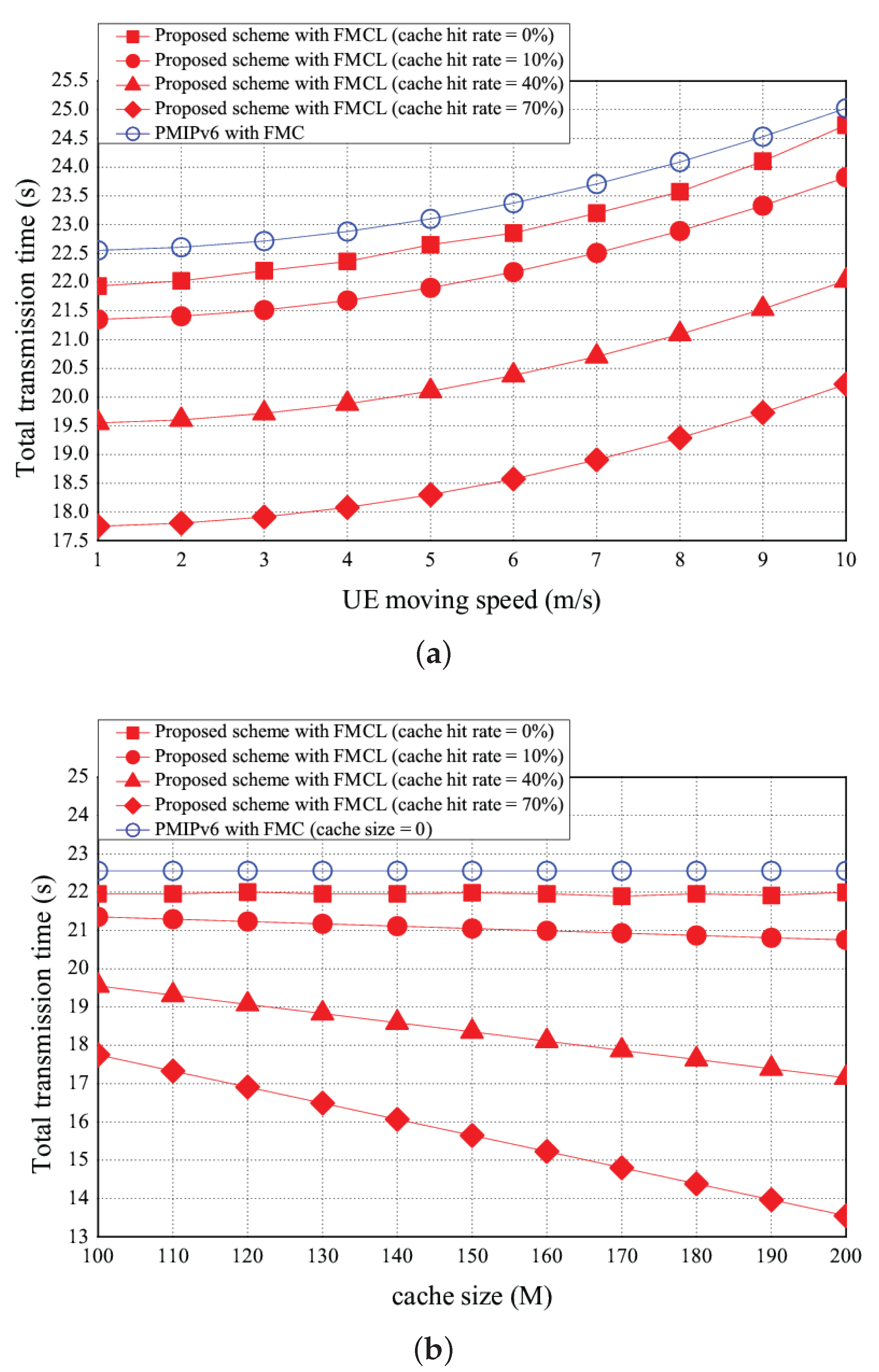
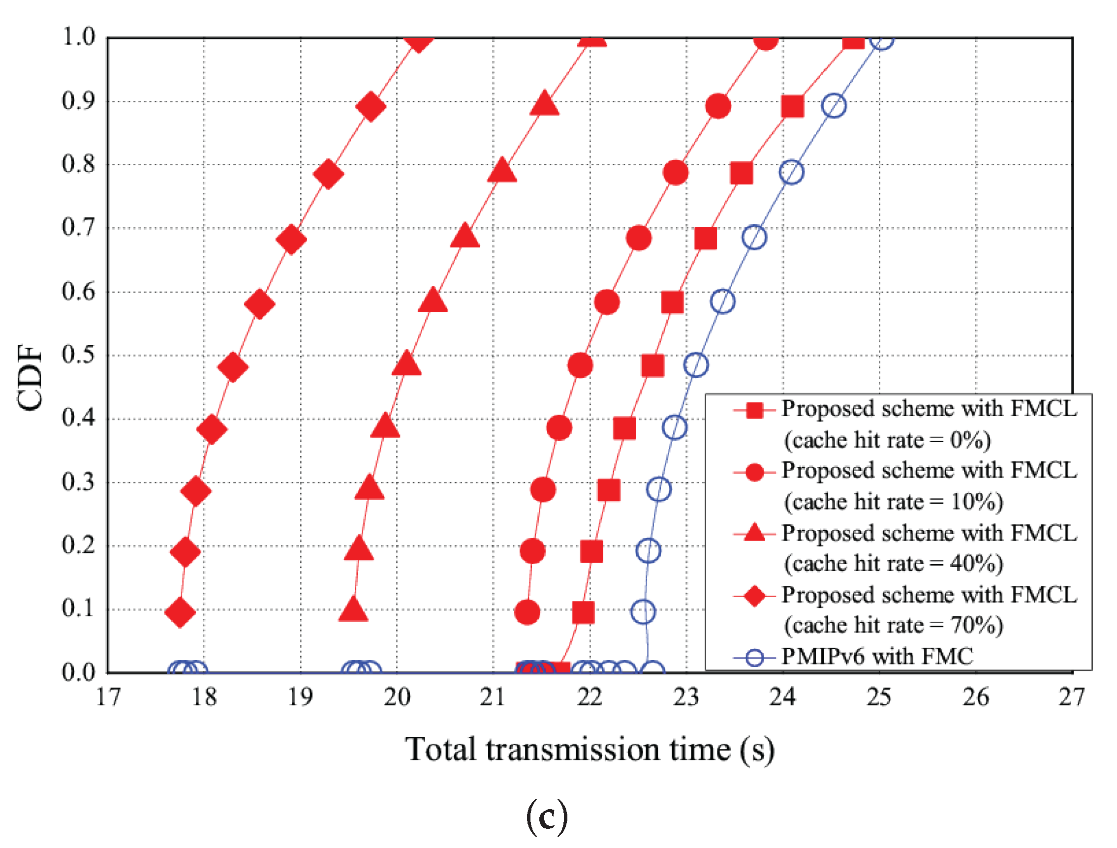
The simulation results of the total transmission time vs. the UE moving speed, the cache size, and CDF (cumulative distribution function) are shown in Figure 12a–c, respectively. As UE moving speed increases, the total transmission time reduces because that the handover frequency increases. The more number of handover requests is, the higher handover latency time will be. As shown in Figure 12a, the total transmission time can be reduced if the more packets can be discovered in the cache. For instance, Figure 12a shows that the total transmission time is 23 s using PMIPv6 with FMC. However, the total transmission time of our proposed scheme with FMCL are 22.6 s, 22 s, 20 s and 18 s if the cache hit rate is 0, 10%, 40%, and 70%, with the UE moving speed fixed at 5 m/s, respectively. Figure 12a shows that the total transmission time of PMIPv6 with FMC was > that of our proposed scheme with FMCL (the cache hit rate = 0%) was > that of our proposed scheme with FMCL (the cache hit rate = 10%) was > our proposed scheme with FMCL (the cache hit rate = 40%) was > our proposed scheme with FMCL (the cache hit rate = 70%) was, under the different UE moving speed. Figure 12b shows the total transmission time vs. the different size of the cache (is ranging from 100 M to 200 M). The higher the size of the cache is, the lower the total transmission time will be. This proposed scheme aims at developing a pre-transmission method to increase the number of packets in cache. For instance, Figure 12b shows that the total transmission time is 22.5 s using PMIPv6 with FMC if the cache size is 150 (M). However, the total transmission time of our proposed scheme with FMCL are 22 s, 21 s, 18.5 s and 15.6 s if the cache hit rate is 0, 10%, 40%, and 70%, if the cache size is 150 (M). Similarly, Figure 12b shows that the total transmission time of PMIPv6 with FMC was > that of our proposed scheme with FMCL (the cache hit rate = 0%) was > that of our proposed scheme with FMCL (the cache hit rate = 10%) was > our proposed scheme with FMCL (the cache hit rate = 40%) was > our proposed scheme with FMCL (the cache hit rate = 70%) was, under the different cache size. In addition, Figure 12c offers the result of CDFvs. the total transmission time.
5.2. Throughput
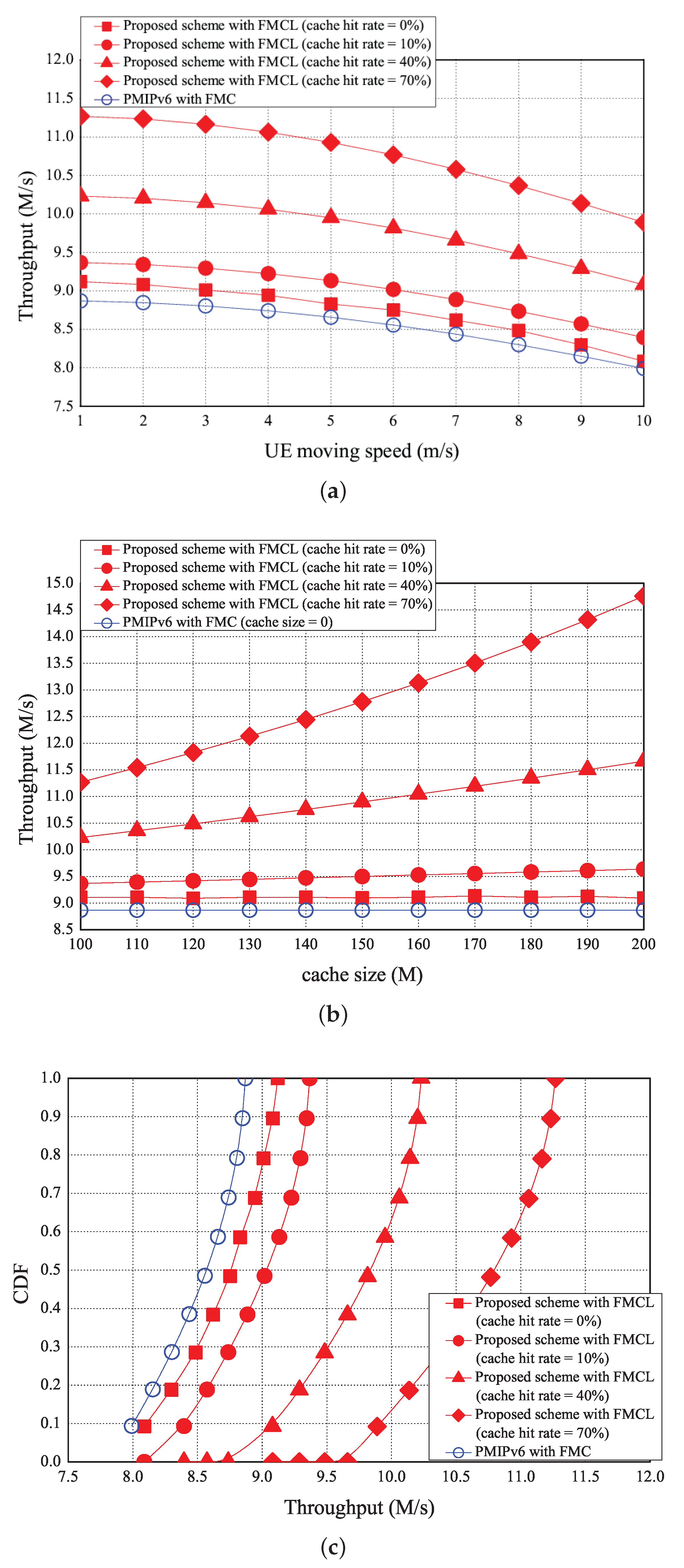
The simulation results of the average throughput vs. the UE moving speed, the cache size, and its CDF are illustrated in Figure 13a–c, respectively. On average, as moving speed increases, the average throughput decrease. As shown in Figure 13a, the usage probability of packets in cache will be decreased if the UE moving speed increases, it implies that the average throughput will be decreases. Figure 13a shows that the average throughput is 8.6 (M/s) using the PMIPv6 with FMC under the UE moving speed is 5 (m/s). However, the average throughput of our proposed scheme with FMCL are 8.8 (M/s), 9 (M/s), 10 (M/s), and 11 (M/s) if the cache hit rate is 0, 10%, 40%, and 70%, under the UE moving speed is 5 m/s, respectively. Figure 13a shows that the average throughput of PMIPv6 with FMC was < that of our proposed scheme with FMCL (the cache hit rate = 0%) was < that of our proposed scheme with FMCL (the cache hit rate = 10%) was < our proposed scheme with FMCL (the cache hit rate = 40%) was < our proposed scheme with FMCL (the cache hit rate = 70%) was, under the different UE moving speed. As shown in Figure 13b, the simulation result of the average throughput vs. the different cache size (is ranging from 100 M to 200 M). As the higher the size of the cache is, the higher the average throughput will be. Figure 13b shows that the average throughput is 8.9 (M/s) using the PMIPv6 with FMC under the UE moving speed is 5 (m/s). However, the average throughput of our proposed scheme with FMCL are 9.1 (M/s), 9.5 (M/s), 10.9 (M/s), and 12.8 (M/s) if the cache hit rate is 0, 10%, 40%, and 70%, under the cache size is 150 (M), respectively. Figure 13b also shows that the average throughput of PMIPv6 with FMC was < that of our proposed scheme with FMCL (the cache hit rate = 0%) was < that of our proposed scheme with FMCL (the cache hit rate = 10%) was < our proposed scheme with FMCL (the cache hit rate = 40%) was < our proposed scheme with FMCL (the cache hit rate = 70%) was, under the different cache size. In addition, the CDF vs. the average throughput is provided in Figure 13c.
5.3. Probability of Packet Loss
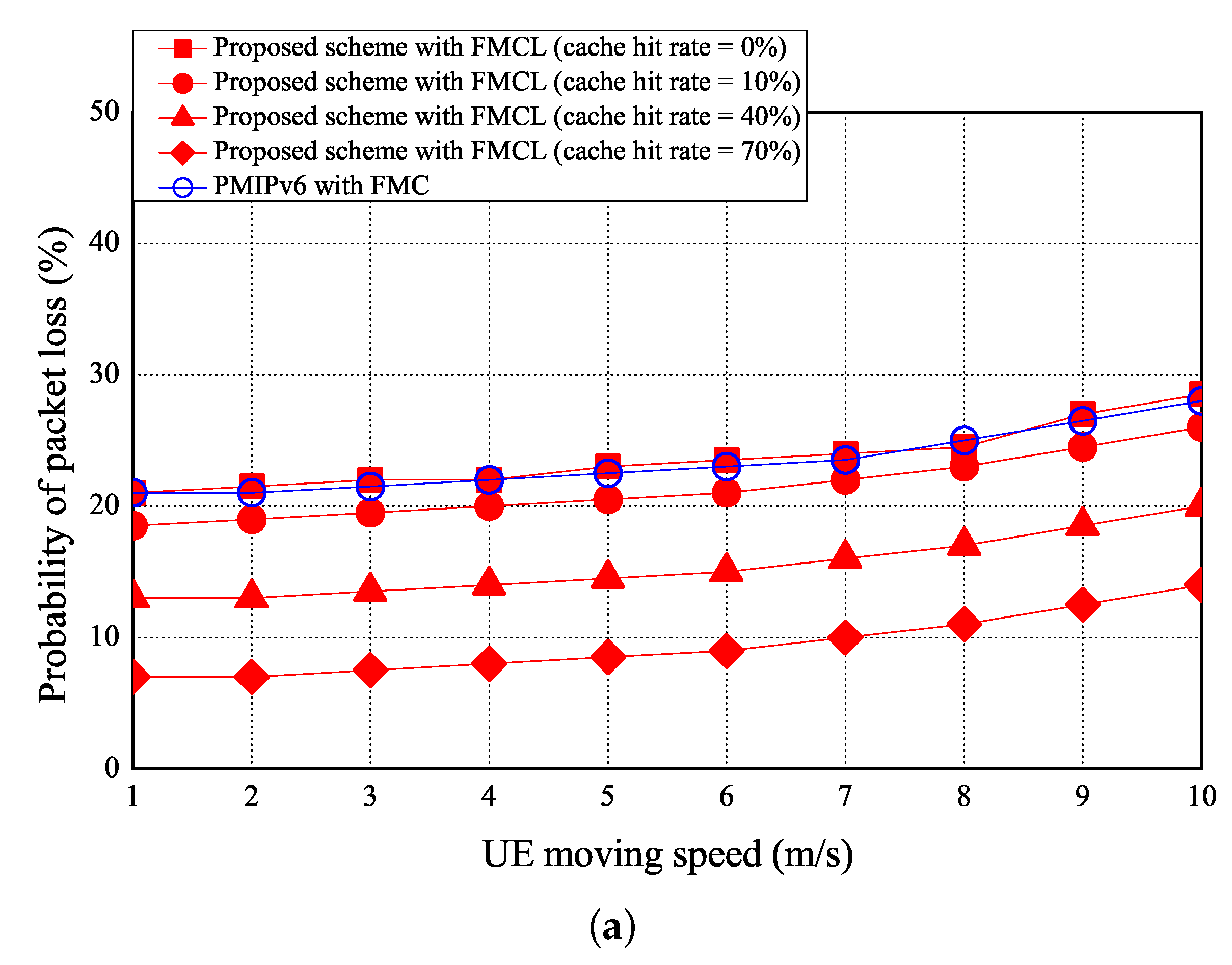
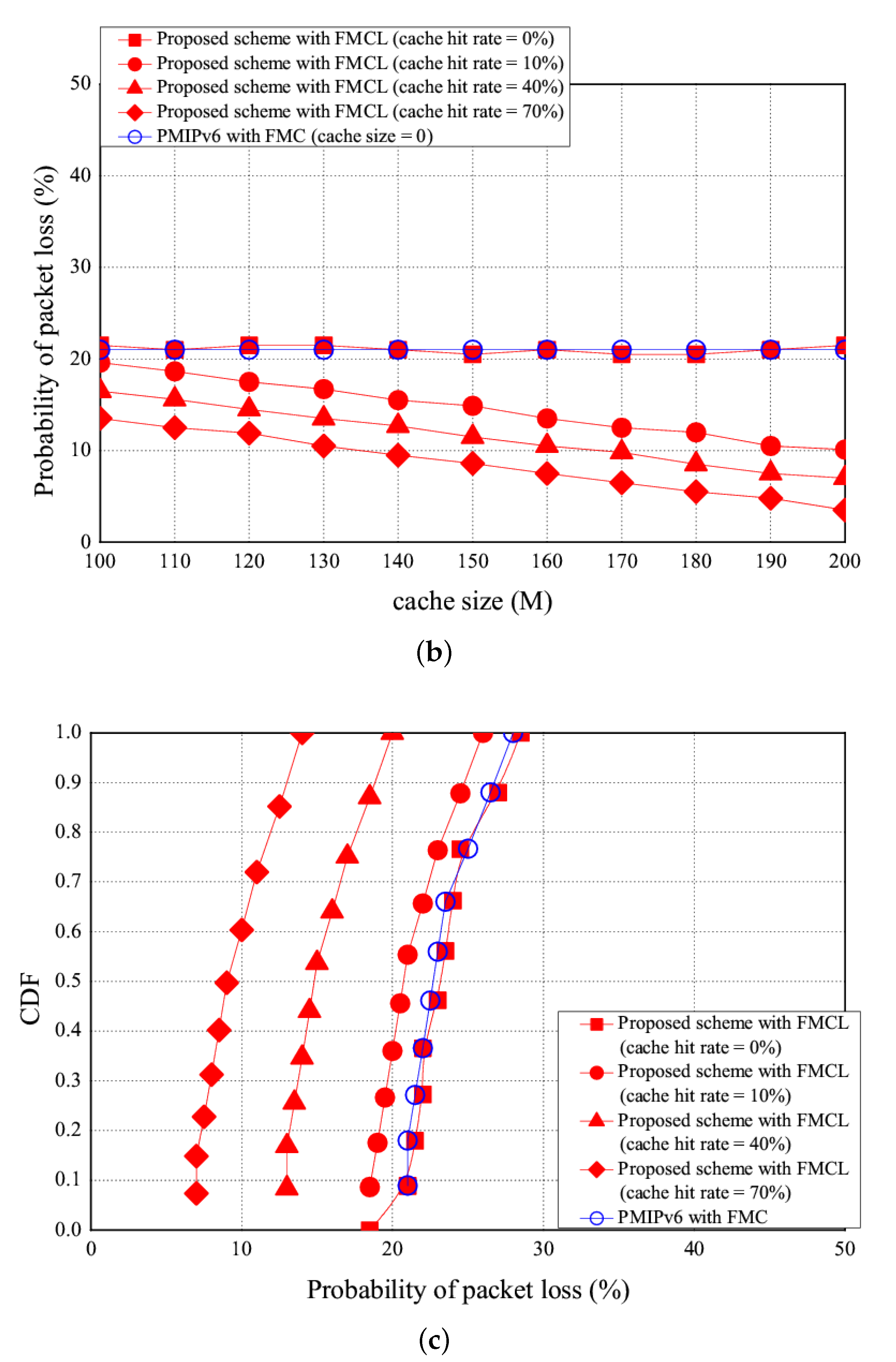
The simulation results of the probability of packet loss v. the UE moving speed, cache size, and CDF are shown in Figure 14a–c, respectively. As the moving speed increases, the probability of packet loss reduces. As shown in Figure 14a, the probability of packet loss can be reduced if the more number of handover events occurred. Figure 14a shows that the probability of packet loss is 22.5 (%) using the PMIPv6 with FMC under the case of the UE moving speed is 5 (m/s). However, the probability of packet loss of our proposed scheme with FMCL are 23 (%), 20.5 (%), 14.5 (%), and 8.5 (%) if the cache hit rate is 0, 10%, 40%, and 70%, under the case of the UE moving speed is 5 m/s, respectively. Figure 14a shows that the probability of packet loss of PMIPv6 with FMC was ≈ that of our proposed scheme with FMCL (the cache hit rate = 0%) was > that of our proposed scheme with FMCL (the cache hit rate = 10%) was > our proposed scheme with FMCL (the cache hit rate = 40%) was > our proposed scheme with FMCL (the cache hit rate = 70%) was, under the different UE moving speed. Figure 14b shows that the simulation result of the probability of packet loss vs. the different cache size (is ranging from 100 M to 200 M). The higher the size of the cache is, the lower probability of packet loss will be. Figure 14b shows that the probability of packet loss is 21 (%) using the PMIPv6 with FMC under the case of the cache size is 150 (M) . However, the probability of packet loss of our proposed scheme with FMCL are 20.5 (%), 15 (%), 11.5 (%), and 8.6 (%) if the cache hit rate is 0, 10%, 40%, and 70%, under the case of the cache size is 150 (M), respectively. Figure 14b also shows that the probability of packet loss of PMIPv6 with FMC was ≈ that of our proposed scheme with FMCL (the cache hit rate = 0%) was > that of our proposed scheme with FMCL (the cache hit rate = 10%) was > our proposed scheme with FMCL (the cache hit rate = 40%) was > our proposed scheme with FMCL (the cache hit rate = 70%) was, under the different cache size. Finally, Figure 14c offers the result of the CDF vs. probability of packet loss.
5.4. Number of Control Messages
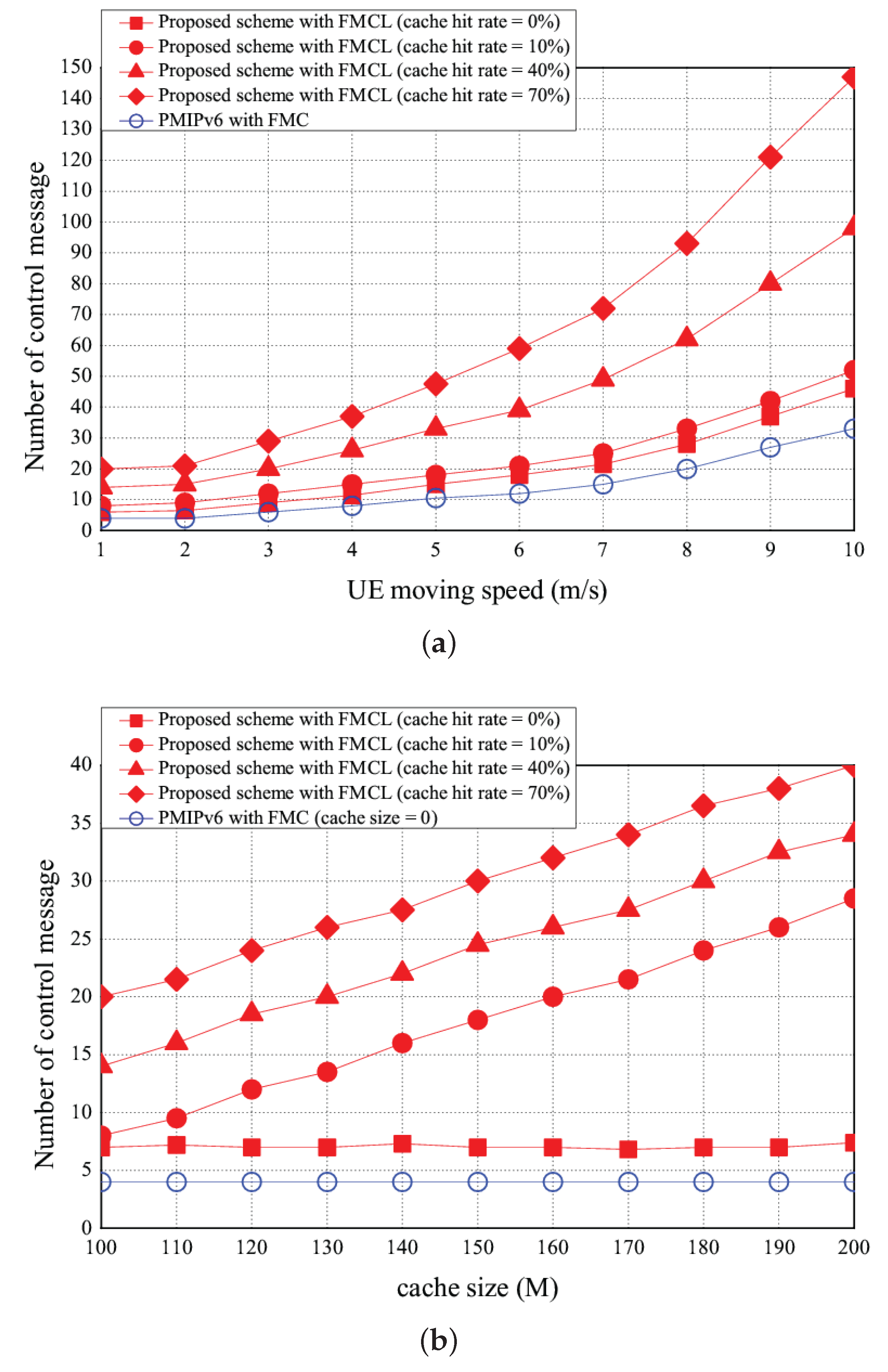
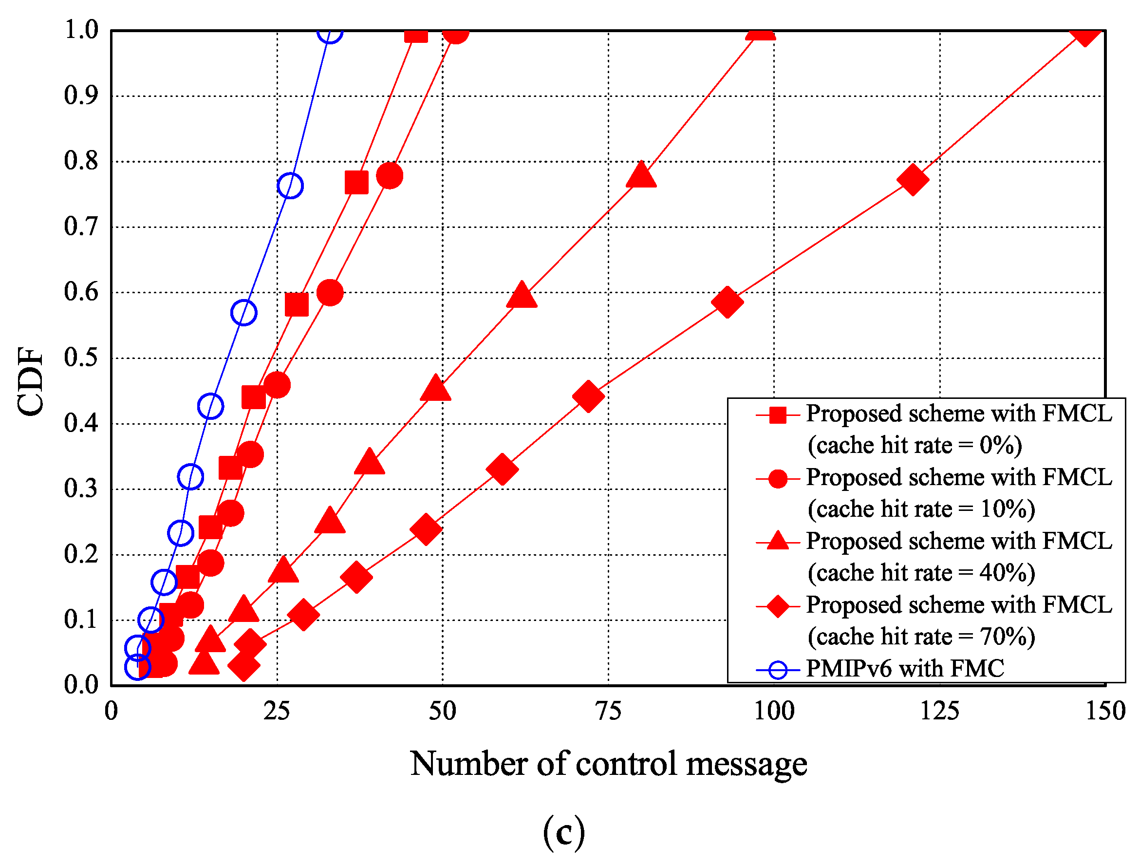
The simulation results of the number of control message vs. the UE moving speed, cache size, and CDF are shown in Figure 15a–c, respectively. As shown in Figure 15a, the the number of control message increases if the more number of handover events occurred. Figure 15a shows that the number of control messages is 10 using the PMIPv6 with FMC under the case of the UE moving speed is 5 (m/s). However, the number of control messages of our proposed scheme with FMCL are 15, 18, 33, and 48 if the cache hit rate is 0, 10%, 40%, and 70%, under the case of the UE moving speed is 5 m/s, respectively. Figure 15a shows that the number of control messages of PMIPv6 with FMC was < that of our proposed scheme with FMCL (the cache hit rate = 0%) was < that of our proposed scheme with FMCL (the cache hit rate = 10%) was < our proposed scheme with FMCL (the cache hit rate = 40%) was < our proposed scheme with FMCL (the cache hit rate = 70%) was, under the different UE moving speed. Figure 15b shows simulation result of the number of control messages vs. the different cache size (is ranging from 100 M to 200 M). The higher cache size is, the higher the number of control message will be. This is because that as the high cache size also implies that the high cache hit rate, so more control messages to needed to communicate with UE and F_AP. Figure 15b shows that the number of control messages is 4 using the PMIPv6 with FMC under the case of the cache size is 150 (M). However, the probability of packet loss of our proposed scheme with FMCL are 7, 18, 24, and 30 if the cache hit rate is 0, 10%, 40%, and 70%, under the case of the cache size is 150 (M), respectively. Figure 15b illustrates that the the number of control messages of PMIPv6 with FMC was < that of our proposed scheme with FMCL (the cache hit rate = 0%) was < that of our proposed scheme with FMCL (the cache hit rate = 10%) was < our proposed scheme with FMCL (the cache hit rate = 40%) was < our proposed scheme with FMCL (the cache hit rate = 70%) was, under the different cache size. Finally, Figure 15c provides the simulation result of CDF vs. the number of control messages.
6. Conclusions
This paper is to propose a new mobility management by using a follow-me cloud-cloudlet (FMCL) approach, which is a cooperation with cloud and cloudlet in Fog-RANs. All existing FMC results do not have the property of the VM migration between cloudlets, and all existing FME results do not have property of the service migration between data centers (DCs). As we can known, it is the first result to report a hybrid scheme by combining FMC and FME schemes into a fully new FMCL approach. The main contribution of the proposed mobility management using FMCL approach is to simultaneously keep the VM migration between cloudlets and service migration between DCs to significantly reduce the transmission latency in Fog-RANs. In addition, our mathematical analysis and simulation results shows that our proposed mobility scheme with FMCL approach outperforms existing FMC result in terms of the total transmission time, the average throughput, and the probability of packet loss, but with the more number of the control messages.
Future work can be further considered the multicast problem using the new proposed FMCL approach in fog-computing-based RAN for smart cities.
Acknowledgments
This work was supported by the National Science Council of China under Grant MOST-106-2221-E-305-007-MY3.
Author Contributions
Yuh-Shyan Chen and Yi-Ting Tsai contributed equally to the main setup, test, measurements, write-up, and towards revising the paper.
Conflicts of Interest
The authors declare no conflict of interest.
References
- Satyanarayanan, M. The emergence of edge computing. IEEE Comput. 2017, 50, 142–149. [Google Scholar] [CrossRef]
- Peng, M.; Yan, S.; Zhang, K.; Wang, C. Fog-computing-based radio access networks: Issues and challenges. IEEE Netw. 2016, 30, 43–46. [Google Scholar] [CrossRef]
- Tandon, R.; Simeone, O. Harnessing cloud and edge synergies: Toward an information theory of fog radio access networks. IEEE Commun. Mag. 2016, 54, 44–50. [Google Scholar] [CrossRef]
- Chan, H. Distributed Mobility Management Specification. Available online: https://tools.ietf.org/html/rfc7333 (accessed on 1 August 2014).
- Giust, F.; Cominardi, L.; Bernardos, C.J. Distributed mobility management for future 5G networks: Overview and analysis of existing approaches. IEEE Commun. Mag. 2015, 53, 142–149. [Google Scholar] [CrossRef]
- Naranjo, P.G.V.; Pooranian, Z.; Shojafar, M.; Conti, M.; Buyya, R. FOCAN: A fog-supported smart city network architecture for management of applications in the internet of everything environments. arXiv, 2017; arXiv:1710.01801. [Google Scholar]
- Taleb, T.; Ksentini, A. Follow me cloud: Interworking federated clouds and distributed mobile networks. IEEE Netw. 2013, 17, 12–19. [Google Scholar] [CrossRef]
- Bittencourt, L.F.; Lopes, M.M.; Petri, I.; Rana, O.F. Towards virtual machine migration in fog computing. In Proceedings of the 10th International Conference on P2P, Parallel, Grid, Cloud and Internet Computing, Kpakow, Poland, 4–6 November 2015; pp. 1–8. [Google Scholar]
- Taleb, T.; Dutta, S.; Ksentini, A.; Iqbal, M.; Flinck, H. Mobile edge computing potential in making cities smarter. IEEE Commun. Mag. 2017, 55, 38–43. [Google Scholar] [CrossRef]
- Liang, K.; Zhao, L.; Chu, X.; Chen, H.H. An integrated architecture for software defined and virtualized radio access networks with fog computing. IEEE Netw. 2017, 31, 80–87. [Google Scholar] [CrossRef]
- Tandon, R.; Simeone, O. Cloud-aided wireless networks with edge caching: Fundamental latency trade-offs in fog radio access networks. In Proceedings of the IEEE International Symposium on Information Theory, Barcelona, Spain, 10–15 July 2016; pp. 2029–2033. [Google Scholar]
- Jalali, F.; Hinton, K.; Ayre, R.; Alpcan, T.; Tucker, R.S. Fog computing may help to save energy in cloud computing. IEEE J. Sel. Areas Commun. 2016, 34, 1728–1739. [Google Scholar] [CrossRef]
- Shih, Y.Y.; Chung, W.H.; Pand, A.C.; Chiu, T.C.; Wei, H.Y. Enabling low-latency applications in fog-radio access networks. IEEE Commun. 2016, 31, 52–58. [Google Scholar] [CrossRef]
- Balfaqih, M.; Ismail, M.; Nordin, R.; Balfaqih, Z.; Yuwono, T. Design and evaluation of network-based distributed mobility management solution based on PFMIPv6. In Proceedings of the 2nd International Conference on Wireless and Telematics, Yogyakarta, Indonesia, 1–2 August 2016; pp. 132–139. [Google Scholar]
- Murtadha, M.K.; Noordin, N.K.; Ali, B.M.; Hashim, F. Design and simulation analysis of network-based fully distributed mobility management in flattened network architecture. Telecommun. Syst. 2017, 65, 253–267. [Google Scholar] [CrossRef]
- Modares, H.; Moravejosharieh, A.; Lloret, J.; Salleh, R.B. A survey on proxy mobile IPv6 handover. IEEE Syst. J. 2016, 10, 208–217. [Google Scholar] [CrossRef]
- Raza, S.M.; Thorat, P.; Challa, R.; Choo, H.; Kim, D.S. SDN based inter-domain mobility for PMIPv6 with route optimization. In Proceedings of the IEEE NetSoft Conference and Workshops, Seoul, Korea, 6–10 June 2016; pp. 24–27. [Google Scholar]
- Wang, Y.; Bi, J.; Zhang, K. Design and implementation of a software-defined mobility architecture for IP networks. ACM Mob. Netw. Appl. 2015, 20, 40–52. [Google Scholar] [CrossRef]
- Yao, L.; Hong, P.; Zhang, W.; Li, J.; Ni, D. Controller placement and flow based dynamic management problem towards SDN. In Proceedings of the IEEE Computer Communications Workshops (ICCW 2015), London, UK, 8–12 June 2015; pp. 363–368. [Google Scholar]
- Garzon, J.P.; Hinojosa, O.A.; Ameigeiras, P.; Ramos-Munoz, J.J.; Andres-Maldonado, P.; Lopez-Soler, J.M. Handover implementation in a 5G SDN-based mobile network architecture. In Proceedings of the IEEE 27th Annual International Symposium on Personal, Indoor, and Mobile Radio Communications (PIMRC 2016), Valencia, Spain, 4–8 September 2016; pp. 1–7. [Google Scholar]
- Wen, R.; Feng, G.; Tan, W.; Ni, R.; Cao, W.; Qin, S. Protocol stack mapping of software defined protocol for next generation mobile networks. In Proceedings of the IEEE International Conference on Communications (ICC 2016), Kuala Lumpur, Malaysia, 22–27 May 2016; pp. 1–6. [Google Scholar]
- Elgendi, I.; Munasinghe, K.S.; Jamalipour, A. Mobility management in three-Tier SDN architecture for denseNets. In Proceedings of the IEEE Wireless Communications and Networking Conference (WCNC 2016), Doha, Qatar, 3–6 April 2016; pp. 1–6. [Google Scholar]
- Carpio, F.; Engelmann, A.; Jukan, A. DiffFlow: Differentiating short and long flows for load balancing in data center networks. In Proceedings of the IEEE Global Communications Conference (GLOBECOM 2016), Washington, DC, USA, 4–8 December 2016; pp. 1–6. [Google Scholar]
- Aissioui, A.; Ksentini, A.; Gueroui, A. PMIPv6-based follow me cloud. In Proceedings of the IEEE Global Communications Conference (GLOBECOM 2015), San Diego, CA, USA, 6–10 December 2015; pp. 1–6. [Google Scholar]
- Nadembega, A.; Hafid, A.S.; Brisebois, R. Mobility prediction Mmdel-based service migration procedure for follow me cloud to support QoS and QoE. In Proceedings of the IEEE International Conference on Communications (ICC 2016), Kuala Lumpur, Malaysia, 22–27 May 2016; pp. 1–6. [Google Scholar]
- Ksentini, A.; Taleb, T.; Chen, M. A markov decision process-based service migration procedure for follow me cloud. In Proceedings of the IEEE International Conference on Communications (ICC 2014), Sydney, NSW, Australia, 10–14 June 2014; pp. 1350–1354. [Google Scholar]
- Taleb, T.; Ksentini, A.; Frangoudis, P. Follow-me cloud: When cloud services follow mobile users. IEEE Trans. Cloud Comput. 2016. [Google Scholar] [CrossRef]
- Shojafar, M.; Cordeschi, N.; Baccarelli, E. Energy-efficient adaptive resource management for real-time vehicular cloud services. IEEE Trans. Cloud Comput. 2016. [Google Scholar] [CrossRef]
- Naranjo, P.G.V.; Pooranian, Z.; Shamshirband, S.; Abawajy, J.H.; Conti, M. Fog over virtualized IoT: New opportunity for context-aware networked applications and a Case Study. Appl. Sci. 2017, 7, 1325. [Google Scholar] [CrossRef]
- Zakrzewska, A.; Ruepp, S.; Berger, M.S. Towards converged 5G mobile networks-challenges and current trends. In Proceedings of the ITU Kaleidoscope Academic Conference: Living in a Converged World—Impossible Without Standards? (ITU 2014), St. Petersburg, Russia, 3–5 June 2014; pp. 39–45. [Google Scholar]
- Park, S.-H.; Simeone, O.; Shamai, S. Joint optimization of cloud and edge processing for fog radio access networks. IEEE Trans. Wirel. Commun. 2016, 15, 7621–7632. [Google Scholar] [CrossRef]
- Peng, X.; Shen, J.-C.; Zhang, J.; Letaief, K.B. Backhaul-aware caching placement for wireless networks. In Proceedings of the IEEE Global Communications Conference (GLOBECOM 2015), San Diego, CA, USA, 6–10 December 2015; pp. 1–6. [Google Scholar]
- Ugur, Y.; Awan, Z.H.; Sezgin, A. Cloud radio access networks with coded caching. In Proceedings of the 20th International ITG Workshop on Smart Antennas (WSA 2016), Berlin, Germany, 9–11 March 2016; pp. 1–5. [Google Scholar]
- Wang, X.; Chen, M.; Taleb, T.; Ksentini, A.; Leung, V. Cache in the air: Exploiting content caching and delivery techniques for 5G systems. IEEE Commun. Mag. 2014, 52, 131–139. [Google Scholar] [CrossRef]
- Ryu: A Component-Based Software Defined Networking Framework. Available online: http://osrg.github.io/ryu/ (accessed on 6 January 2018).
- Mininet: An instant virtual network on your laptop. In Proceedings of the 2017 ACM SIGCOMM SOSR Software Systems Award, Santa, Clara, 3–4 April 2017.
Figure 1.
System architecture.

Figure 2.
(a) Fog-RAN architecture using follow me cloud-cloudlet and (b) its simplified architecture.
Figure 2.
(a) Fog-RAN architecture using follow me cloud-cloudlet and (b) its simplified architecture.

Figure 3.
Comparison of (a) PMIPv6-based follow me cloud and (b) our proposed scheme using follow me cloud-cloudlet.
Figure 3.
Comparison of (a) PMIPv6-based follow me cloud and (b) our proposed scheme using follow me cloud-cloudlet.

Figure 4.
Basic operations of (a) cooperation of cloud-cloudlet and (b) cooperation of cloud-cloudlet .
Figure 4.
Basic operations of (a) cooperation of cloud-cloudlet and (b) cooperation of cloud-cloudlet .

Figure 5.
Basic operations of (a) cooperation of cloud-cloudlet and (b) cooperation of cloud-cloudlet .
Figure 5.
Basic operations of (a) cooperation of cloud-cloudlet and (b) cooperation of cloud-cloudlet .

Figure 6.
Message flow diagrams of (a) PMIPv6-based FMC approach and (b) our proposed mobility management using FMCL approach.
Figure 6.
Message flow diagrams of (a) PMIPv6-based FMC approach and (b) our proposed mobility management using FMCL approach.

Figure 7.
An example of follow me phase.

Figure 8.
An example of follow me cloudlet phase.

Figure 9.
An example of follow me cloud phase.

Figure 10.
An example of follow me cloud-cloudlet phase.

Figure 11.
Example of the time and space costs of (a) proxy MIPv6-based FMC, and our proposal scheme with FMCL if (b) and (c) and
Figure 11.
Example of the time and space costs of (a) proxy MIPv6-based FMC, and our proposal scheme with FMCL if (b) and (c) and

Figure 12.
Total transmission time vs. (a) UE moving speed and (b) cache size, and (c) CDF vs. the total transmission time.
Figure 12.
Total transmission time vs. (a) UE moving speed and (b) cache size, and (c) CDF vs. the total transmission time.


Figure 13.
Throughput vs. (a) UE moving speed. and (b) cache size, and (c) CDF vs. throughput.

Figure 14.
Probability of packet loss vs. (a) UE moving speed and (b) cache size, and (c) CDF vs. probability of packet loss.
Figure 14.
Probability of packet loss vs. (a) UE moving speed and (b) cache size, and (c) CDF vs. probability of packet loss.


Figure 15.
Number of control messages vs. (a) UE moving speed and (b) cache size, and (c) CDF vs. number of control messages.
Figure 15.
Number of control messages vs. (a) UE moving speed and (b) cache size, and (c) CDF vs. number of control messages.


Table 1.
Simulation environment and parameters.
| Parameter | Value |
|---|---|
| Simulation tools | Ryu SDN frame-work Mininet |
| Bandwidth per link | 10 Mbps |
| Data file size | 200 M |
| Number of F-AP | 2 |
| Number of DC | 2 |
| Number of UEs | 0 to 50 |
| Packet size | Uniform distribution with min = 84, max = 500 bytes |
© 2018 by the authors. Licensee MDPI, Basel, Switzerland. This article is an open access article distributed under the terms and conditions of the Creative Commons Attribution (CC BY) license (http://creativecommons.org/licenses/by/4.0/).
Share and Cite
MDPI and ACS Style
Chen, Y.-S.; Tsai, Y.-T. A Mobility Management Using Follow-Me Cloud-Cloudlet in Fog-Computing-Based RANs for Smart Cities. Sensors 2018, 18, 489. https://0-doi-org.brum.beds.ac.uk/10.3390/s18020489
AMA Style
Chen Y-S, Tsai Y-T. A Mobility Management Using Follow-Me Cloud-Cloudlet in Fog-Computing-Based RANs for Smart Cities. Sensors. 2018; 18(2):489. https://0-doi-org.brum.beds.ac.uk/10.3390/s18020489
Chicago/Turabian StyleChen, Yuh-Shyan, and Yi-Ting Tsai. 2018. "A Mobility Management Using Follow-Me Cloud-Cloudlet in Fog-Computing-Based RANs for Smart Cities" Sensors 18, no. 2: 489. https://0-doi-org.brum.beds.ac.uk/10.3390/s18020489
Note that from the first issue of 2016, this journal uses article numbers instead of page numbers. See further details here.