An Improved Adaptive Received Beamforming for Nested Frequency Offset and Nested Array FDA-MIMO Radar


1
National Key Laboratory of Mechatronic Engineering and Control, Beijing Institute of Technology, Beijing 100081, China
2
Beijing Institute of Spacecraft System Engineering, Beijing 100086, China
*
Author to whom correspondence should be addressed.
Sensors 2018, 18(2), 520; https://0-doi-org.brum.beds.ac.uk/10.3390/s18020520
Submission received: 25 December 2017
/
Revised: 2 February 2018
/
Accepted: 5 February 2018
/
Published: 8 February 2018
(This article belongs to the Special Issue First Experiences with Chinese Gaofen-3 SAR Sensor)
Abstract
:For the conventional FDA-MIMO (frequency diversity array multiple-input-multiple-output) Radar with uniform frequency offset and uniform linear array, the DOFs (degrees of freedom) of the adaptive beamformer are limited by the number of elements. A better performance—for example, a better suppression for strong interferences and a more desirable trade-off between the main lobe and side lobe—can be achieved with a greater number of DOFs. In order to obtain larger DOFs, this paper researches the signal model of the FDA-MIMO Radar with nested frequency offset and nested array, then proposes an improved adaptive beamforming method that uses the augmented matrix instead of the covariance matrix to calculate the optimum weight vectors and can be used to improve the output performances of FDA-MIMO Radar with the same element number or reduce the element number while maintain the approximate output performances such as the received beampattern, the main lobe width, side lobe depths and the output SINR (signal-to-interference-noise ratio). The effectiveness of the proposed scheme is verified by simulations.
1. Introduction
As a new kind of MIMO Radar, the FDA-MIMO Radar has drawn much attention, and has been widely investigated since the introduction of the concept of the “frequency diversity array”. In contrast to the traditional MIMO Radar, the FDA-MIMO Radar consists of a beampattern that expands from the angle domain to the joint angle-range domain by utilizing a small frequency offset across the array [1]. Previous research has shown that the beampattern periodically changes with the following parameters: angle, range and time [2,3,4]. Simulation results for transmitted beampattern have been achieved by evaluating the effect of frequency offset, range, angle, antenna element spacing, as well as other factors [5],with the authors proposing that “FDA-MIMO Developments: Windowing and Nonlinear Frequency Shift”. Furthermore, in [6,7], the authors investigated the FDA-MIMO Radar with jamming signals, and established mathematical models for the FDA-MIMO Radar received signals and its jamming signals.
In recent years, the FDA-MIMO Radar has continued toplace a lot of emphasis on the exploitation of the benefits that are exclusive to the joint angle-range domain. In particular, range-angle location and estimation has been a popular research subject [7,8,9,10]. For instance, a joint range-angle estimation algorithm is presented in [7]; a FDA-MIMO Radar with double pulsewas proposed, with the aim ofimproving the range-angle localization of the target [8]. Another popular area of FDA-MIMO Radar research is related to optimizing nonuniform frequency offset to obtain modified range-angle beampattern or better output performance [11,12,13,14,15]. As discussed in [11], the logarithmic frequency offset allows a single maxima for each beam, ensuring that the signal information at the receiver is of better quality. Moreover, square increasing and cubic frequency offset are recommended for the FDA-MIMO Radar, so that the targets’ range and angle can be estimated without ambiguities [12]. A cognitive FDA-MIMO Radar with situational awareness is researched to maximize the output SINR by iteratively optimizing the frequency offset in a closed-loop control manner [13]. In [15], the authors took advantage of an optimal frequency increment selection method by maximizing the SINR in each coherent processing interval for the FDA-MIMO Radar, and also discuss a corresponding target discrimination method. Nevertheless, to the best of our knowledge, less attention has been paid to tapping the potential of nonuniform frequency offset in increasing the DOFs while keeping the same element number.
Larger DOFs in the angle domain have been achieved by choosing a suitable nonuniform array (or sparse array), such as MRA (minimum redundancy array) [16], co-prime array [17], and nested array [18]. As mentioned above, the beampattern of FDA-MIMO Radar, which involves the joint angle-range domain and the corresponding DOFs, is decided by both the frequency offset and the array interval. Consequently, increasing the DOFs in the FDA-MIMO Radar has to be achieved based on these two aspects. We research the signal model of the FDA-MIMO Radar with nested frequency offset and nested array, and propose an improved MVDR (Minimum Variance Distortionless Response) beamforming. Rather than directly using the covariance matrix obtained from the received data matrix, the improved MVDR beamforming method augments the covariance matrix of the received data with a new Toeplitz matrix that can provide greater DOFs. By using the new matrix in the MVDR beamforming, the resultant beampattern has lower side lobes and higher SINR than the conventional MVDR beamforming, which utilizes the covariance matrix in a direct manner.
The rest of the paper is organized as follows: Signal models of the collocated FDA-MIMO Radar with nested frequency offset and nested array are presented in Section 2. This Section explains the specific process of the improved MVDR beamforming. Simulations and discussions are shown in Section 3, followed by the conclusions in Section 4.
2. Signal Models of the Collocated NNFDA-MIMO Radar
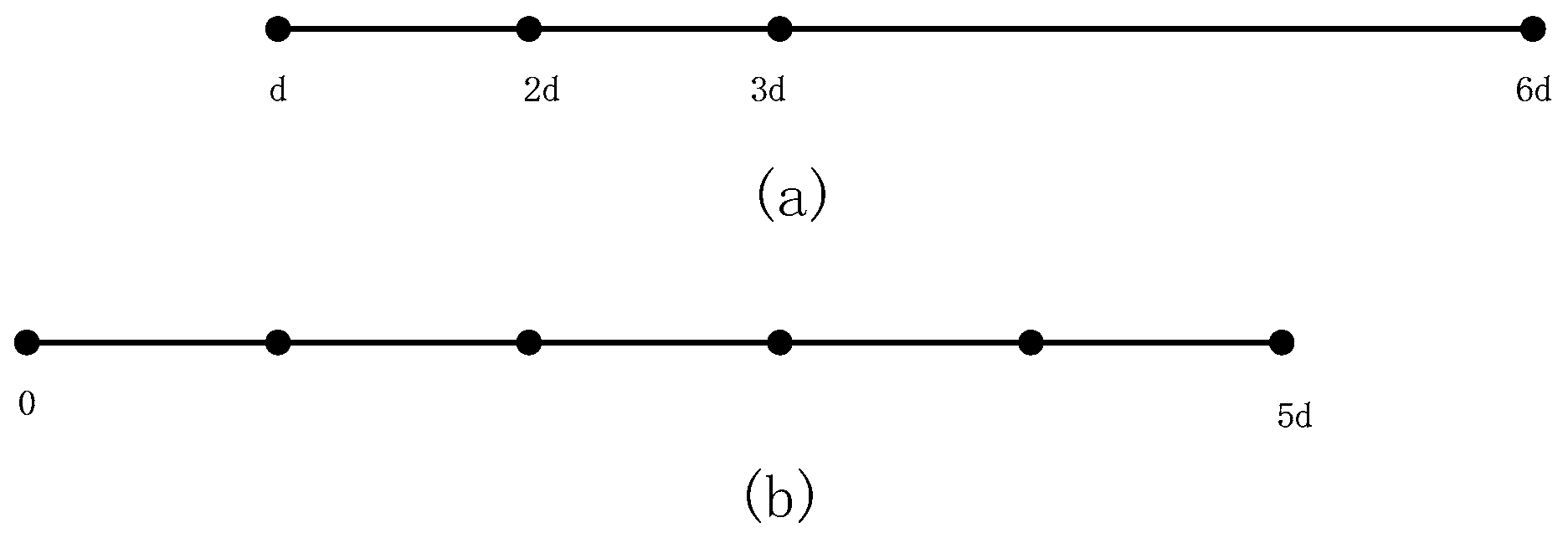
An N-element collocated FDA-MIMO Radar with the nested array and the nested frequency offset, namedan NNFDA-MIMO Radar, transmits signals and receives the echo signals using the same two-level nested array. A two-level nested array is basically a concatenation of two ULAs (uniform linear arrays): inner ULA and outer ULA, where the inner ULA has elements with interval and the outer ULA has elements with interval . The array intervalof each omnidirectional element is half wavelength, expressed as , is the light speed. When is even, , while when is odd, and . Consequently, for the N-element two-level nested array, the position set is .
To illustrate the difference between the two-level nested array and ULA, we show sketches of the 4-element two-level nested array and the 6-element ULA in Figure 1a,b.
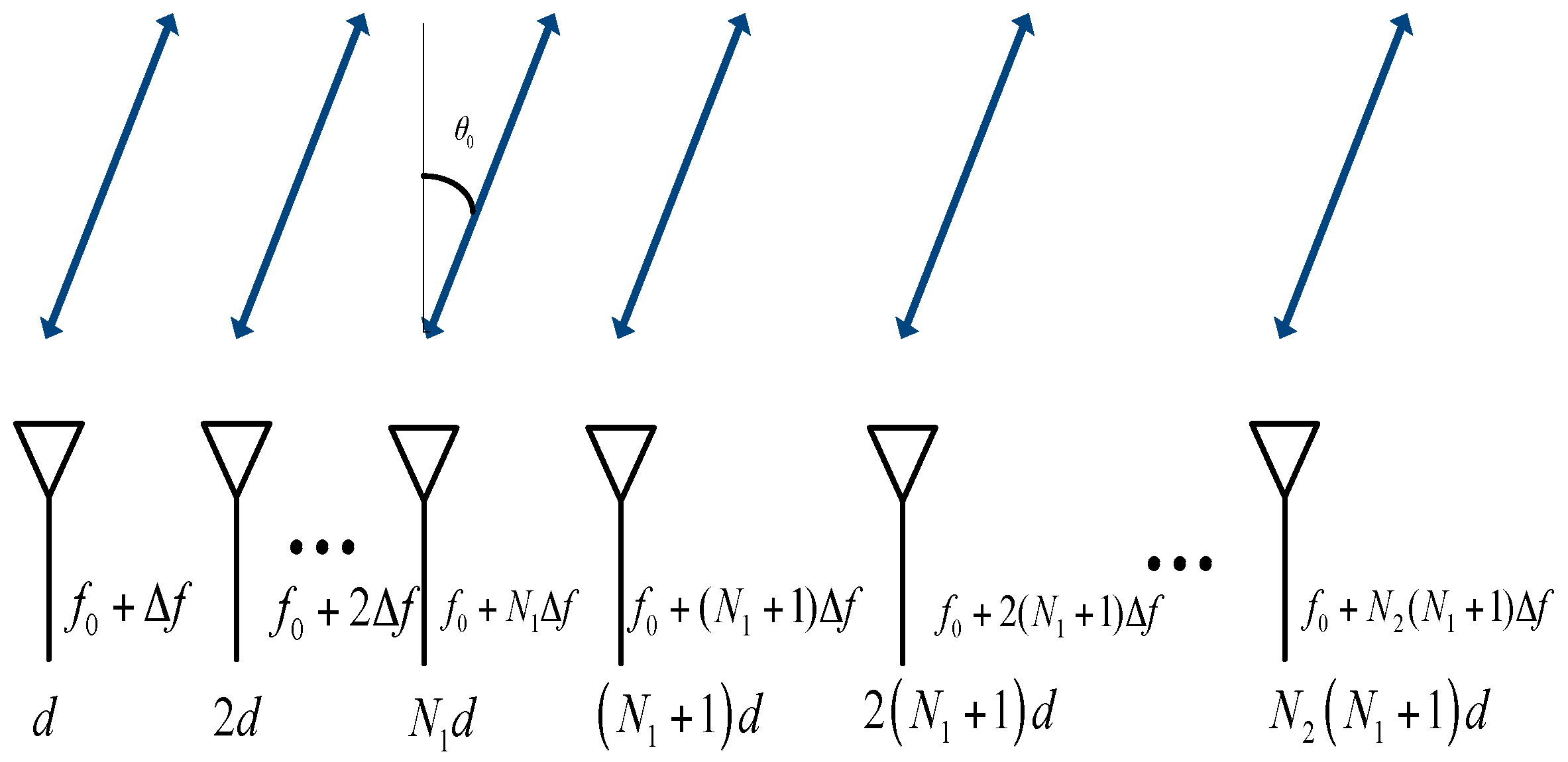
The nth transmit element’s carrier frequency is expressed as
where is the reference carrier frequency and is the frequency offset, which is negligible compared with . is the nth element of the set , when is even, while and when is odd. The N-element collocated NNFDA-MIMO Radar is shown schematically in Figure 2.
Given the far-field point target at range and from angle , the signal ,which is transmitted by the nth element, reflected by the target, then received by the mth element and finally matched-filtered, can be written as
where and is the complex-valued coefficient of the point target. The received snapshot of target in FDA-MIMO can be expressed in the vector form as
where “” denotes the Kronecker product operator and the superscript T is the transpose operator. is the virtual steering vector, and are the transmit steering vector and receive steering vector respectively, expressed as
The received snapshot has the following components: the target component , the interference component and the noise component . Assume that there are interferences impinging on the array from the direction . The received interference component can be expressed as [7]
where is a zero-mean circularly symmetric complex Gaussian random variable with variance , the superscript H is the conjunctive transpose operator. The is the noise-like transmit steering vector of the noise jamming and assumed zero-mean white Gaussian distribution [19]. The is the receive steering vector of the noise jamming, and takes the form .
Hence, the total received snapshot can be written as
There is an assumption that the noise is temporally-spatially white, and temporally uncorrelated from each signal. Additionally, the interferences are statistically noise-like and oppressive. The matrix is defined as the interferences’ covariance matrix, is the identity matrix. For the N-element collocated NNFDA-MIMO Radar, the covariance matrix can be expressed as
where is the desired signal’s power, is the identity matrix, is the noise power and is the interference signal’s power.
For matrices , , , , and . Hence, it can be obtained
The covariance matrix can further be formed as
Now, we define , and . There is
Each element of matrix , and can be formed as
where is the th element of , and represent the th element of and , respectively. The function returns the modulus after division of by , while the function returns the first integer when . According to the definition of the Kronecker product, is the th element of the matrix ( size) and can be decomposed as
where is the delta function that equals 1 when and 0 when .
Here are two definitions:
Hence, is simplified as
The principle of MVDR beamforming is minimizing the output’s variance while constraining the response of the desired signal to unity [18]. By using the augmented matrix instead of directly obtained from the received snapshot, we obtain a new MVDR beamformer with an optimal weight vector. It can be easily seen that the elements in depend on the values of and . The value of is only decided by the array interval, while the value of is dependent on both the frequency offset and the array interval. For the N-element collocated NNFDA-MIMO Radar, and are both elements of the following vector .
where .
The size of is , so for the N-element collocated NNFDA-MIMO Radar, the covariance matrix has distinct elements, and its size is , which means the DOFs of the adaptive beamformer is equal to [20]. Furthermore, the elements’ order of arrangement in the matrix is given in (18), since there are distinct elements in matrix , while the number of DOFs is just . Next, we decide to rearrange the distinct elements in matrix in a new order to augment the size of matrix and obtain more DOFs, which could improve the output performances of the beampattern.
Firstly, we define , is the nth element of the set and a Toeplitz matrix , and it has distinct elements and can be decomposed in the following Kronecker product operator forms
where , , , are Toeplitz matrices and is a diagonal matrix. Combing the property “a linear combination of the Toeplitz matrices is still a Toeplitz matrix”, the desired Toeplitz matrix, reconstructed by the set , can be written as
where is the identity matrix while is the identity matrix, the Toeplitz matrix , , the Toeplitz matrix , and the Toeplitz matrix , . Define the new virtual steering vector . is the th element of the matrix , written as
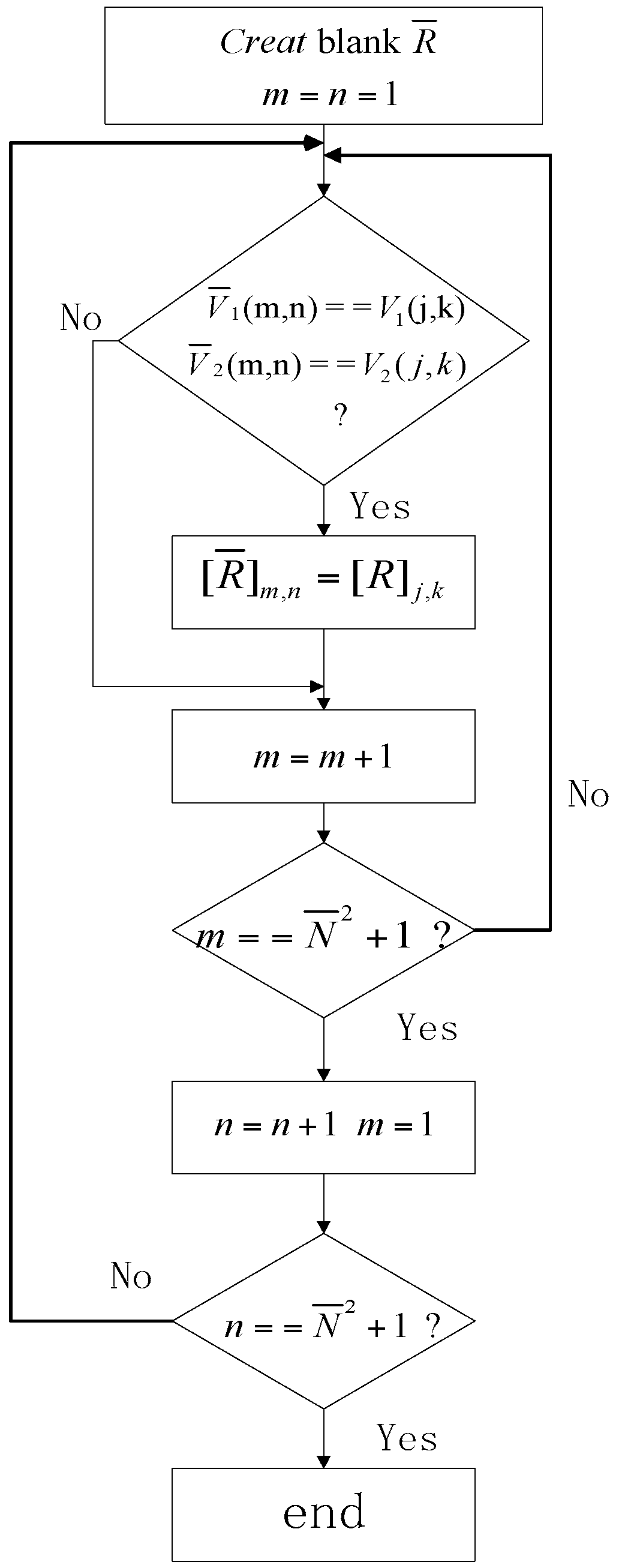
In order to reconstruct the matrix , we need to augment the size of matrix , so we name the Toeplitz matrix as the corresponding augmented matrix and the augmenting process is carried out as follows:
Step (1): Create a blank matrix and assign the initial values ;
Step (2): Search the element in the matrix ( size), if and , assign the value of ;
Step (3): Judge the value of m: if , assign and let , otherwise let ;
Step (4): Judge the value of n: if , finish the augmenting process and obtain the desired matrix described above, otherwise repeat the Step (2);
The diagram is shown as Figure 3.
where is the new desired virtual steering vector, defined above and formed as
Since the weight vector has a dimension , the DOFs number of the adaptive beamformer (using augmented matrix ) is . If the covariance matrix is used directly, the DOFs is , although the two matrices have the same distinct elements. Referring to the two-level nested array, the optimal values , and the corresponding DOFs of the adaptive beamformer are listed in Table 1.
It can be easily seen that when , which means that larger DOFs for the adaptive beamformer can be obtained from the augmented matrix . Compared with the traditional method, which increases the DOFs by using more antenna elements, the NNFDA scheme utilizes the advantages of NLA and incorporates the reconstruction method to obtain the virtual matrix, having equal DOFs to the larger ULA. The larger DOFs are able to improve the output beamformer performances; namely, in terms of a better trade-off between the main lobe width and side lobes levels, and the higher SINR.
The normalized received beampattern and the output SINR are respectively given as
3. Simulations and Discussions
In the numerical simulations, the reference carrier frequency is , the frequency offset is set as and the snapshot number is 500. The target is assumed to be located at a range and in the direction . We consider the 8-element collocated NNFDA-MIMO Radar, the ith (i = 1, 2, 3, …, 8) element carrier frequency is the ith element of the set , and the set of the antennas’ positions is . From the 8-element collocated NNFDA-MIMO Radar’s received snapshots, we can obtain two resultant MVDR beamformings with different DOFs. One is obtained by directly using the covariance matrix while the other one utilizes the augmented matrix. In order to distinguish and compare the two MVDR beamforming results more clearly, we name the one that directly uses the covariance matrix as NNFDA direct, and the other one is NNFDA augmented. A better performance—for example, a better suppression of strong interference and a higher energy concentration—can be achieved with a greater number of DOFs [18,20]. To verify this, this paper introduces another two conventional FDA-MIMO Radars, the 8-element FDA-MIMO Radar and 20-element FDA-MIMO Radar, to carry out the simulations and comparisons. The noise is assumed to be White Gaussian Noise, and the SNR is equal to 0dB. In addition, the interferences, as described in (6), impinge the array from directions . For each interference, its interference-to-noise ratio (INR) is 10dB. The four DOFs and number of distinct elements are provided in Table 2.
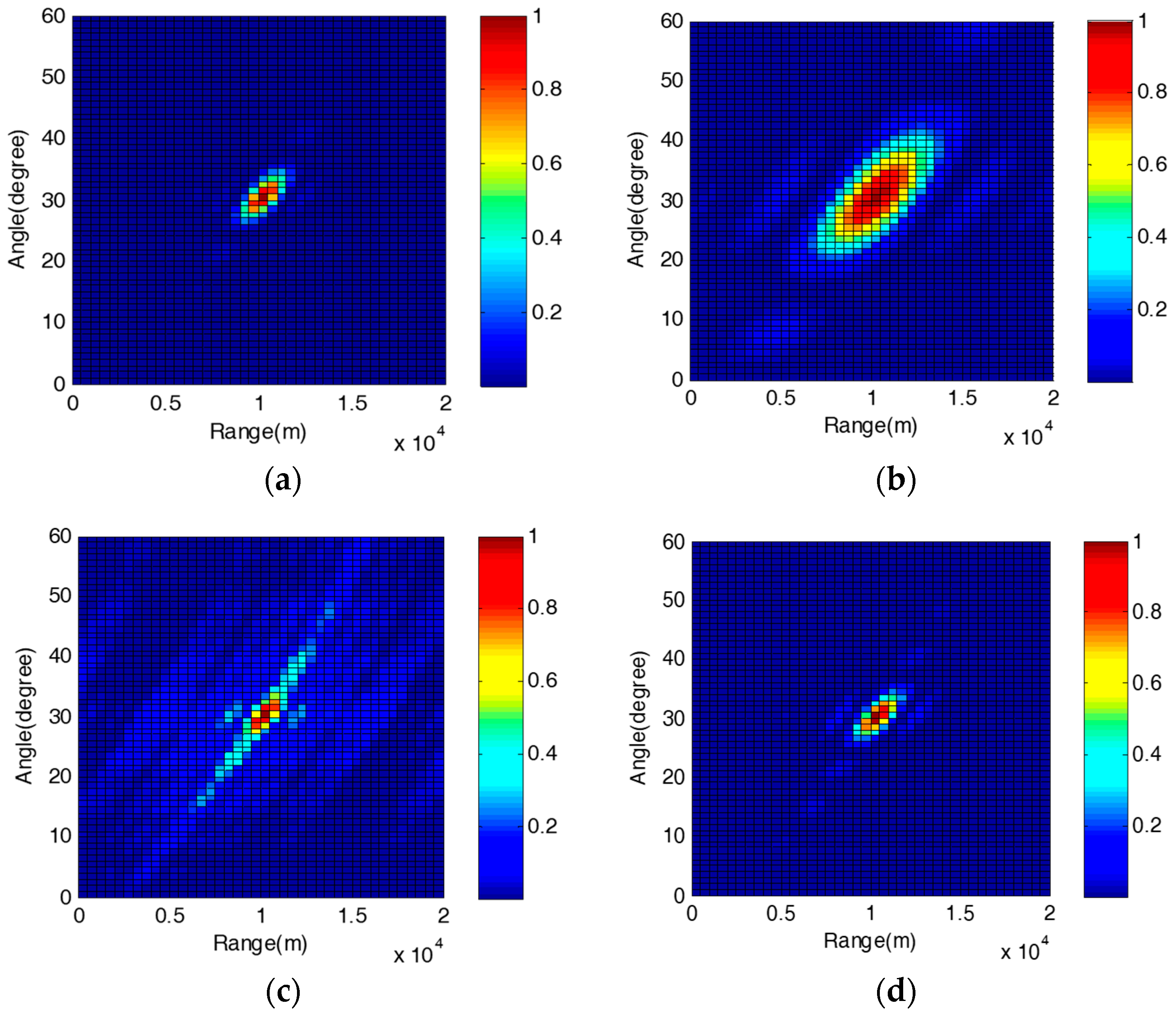
Figure 4a–d shows the normalized beampatterns of the Radars listed in Table 2. It can be found that the four normalized beampatterns’ peaks appear at the same point (10 km, 30°), which is the desired location of the target indeed. Hence, the effectiveness of the MVDR beamforming, for the FDA-MIMO Radar and NNFDA-MIMO Radar, can be verified. For the conventional FDA-MIMO Radar, a greater number of DOFs always means a sharper beampattern, but depends on more elements. Comparing Figure 4a,b, we find that the normalized beampattern of 20-element FDA-MIMO Radar (DOFs 400) obviously has a narrower main-lobe than the one of the 8-element FDA-MIMO Radar (DOFs 64). However, for the NNFDA-MIMO Radar, we can utilize the MVDR beamforming based on the augmented matrix to increase the DOFs, instead of only relying on a larger array. Figure 4c,d provides the resultant beampatterns of the 8-element NNFDA direct and 8-element NNFDA augmented. They have approximately the same main lobe width, but the latter possesses obviously lower side lobe levels, due to the increased DOFs (from 64 to 400). Figure 4c,d verifies the effectiveness and necessity of the augmented matrix, introduced in Section 3. Furthermore, although the numbers of elements in Figure 4b,d are the same, the normalized beampattern of 8-element NNFDA augmented is significantly better than the one of the 8-element FDA in terms of main lobe width and side lobe depth. The NNFDA-MIMO Radar can improve normalized beampattern with the same number of elements.
In order to visually display the normalized beampatterns’ main-lobe width, Figure 5 plots the −3dB sectional areas which can effectively reflect the main lobes’ energy concentration performance. In Figure 5, the 20-element FDA-MIMO Radar, the 8-element NNFDA-MIMO Radar augmented and the 8-element NNFDA-MIMO Radar direct have nearly the same −3dB sectional area of beampattern, which is significantly narrower than the one of the 8-element FDA-MIMO Radar. Because those three have the same maximum aperture of equivalent antenna in theory. Through Figure 5, it can be concluded that the proposed FDA-MIMO Radar scheme can reduce the element number while maintaining the approximate normalized beampatterns’ main lobe width.
The results of the range scanning at the desired direction () are provided in Figure 6a. Among the four corresponding results, there are three (20-element FDA, 8-element NNFDA augmented, 8-element NNFDA direct) possessing nearly the same main lobe beam width, because their covariance matrices or augmented matrix, used for the received beamforming, have the same number of distinct elements. However, due to their having equal DOFs, the side lobes of the 8-element NNFDA augmented and the 20-element FDA are nearly identical to one another, but are much lower than those of 8-element NNFDA direct. A similar situation appears in Figure 6b, which shows the results of the angle scanning at the desired range (). Generally, the resolution is defined as the width of the −3dB range in the normalized pattern, so we can assume that the received beampatterns of 20-element FDA and 8-element NNFDA augmented have a similar angle resolution and range resolution.
The output SINR versus the input SINR for the described MVDR beamformers are plotted in Figure 7, where the input SINR is changed from −30dB to 30dB while the other parameters are the same as those in Figure 4. Through Figure 7, it can be concluded that in the aspect of robustness against the noise and interference, the 8-element NNFDA augmented beamformer is quite same to the 20-element FDA beamformer, but better than the 8-element NNFDA direct beamformer and the 8-element FDA beamformer.
4. Conclusions
In order to obtain larger DOFs, this paper researches the signal model of the FDA-MIMO Radar with nested frequency offset and nested array, then proposes an improved adaptive beamforming method that can provide a better beamforming performance, including narrower main lobe width, lower side lobes, and a higher output SINR, as shown in the simulations. Furthermore, the proposed method provides a novel working mode for the existing FDA-MIMO Radar. Such a mode can reduce hardware expense, as the process of the augmented matrix is not complex, creating a new array by selecting fewer elements to support a fully functional radar, rather than letting the whole array work as the traditional mode does. More importantly, the corresponding resultant received beampatterns obtained by the two different modes have the nearly same output performance.
Acknowledgments
This work was supported by the National Science Foundation of China (NSFC) (Grant 61673066) and Target Orientation Detection Technology Project (995-140210060102).
Author Contributions
Sibei Cheng contributed in the conception and design of the study, simulation performing and manuscript drafting. Qingjun Zhang participated in the design of the study and helped perform the analysis of the results. Mingming Bian and Xinhong Hao revised the manuscript and proposed constructive discussions for the final manuscript. All authors have read and approved the final manuscript.
Conflicts of Interest
The authors declare no conflict of interest.
Abbreviations
| FDA-MIMO | frequency diversity array multiple-input-multiple-output |
| NNFDA-MIMO | nested frequency offset and nested array FDA-MIMO |
| ULA | uniform linear array |
| DOFs | degrees of freedom |
| SINR | Signal to interference noise ratio |
| MRA | minimum redundancy array |
| MVDR | minimum variance distortionless response |
References
- Antonik, P.; Wicks, M.; Griffiths, H.; Baker, C. Frequency diverse array radars. In Proceedings of the IEEE Radar Conference, Verona, NY, USA, 24–27 April 2006; pp. 215–217. [Google Scholar]
- Secmen, M.; Demir, S.; Hizal, A.; Eker, T. Frequency diverse array antenna with periodic time modulated pattern in range and angle. In Proceedings of the 2007 IEEE Radar Conference, Piscataway, NJ, USA, 17–20 April 2007; pp. 427–430. [Google Scholar]
- Sammartino, P.F.; Baker, C.J. The frequency diverse bistatic system. In Proceedings of the Fourth International Conference on Waveform Diversity and Design, Kissimmee, FL, USA, 8–13 February 2009; pp. 155–159. [Google Scholar]
- Huang, J.; Tong, K.F.; Woodbridge, K.; Baker, C. Frequency diverse array: Simulation and design. In Proceedings of the IEEE Radar Conference, Pasadena, CA, USA, 4–8 May 2009; pp. 1–4. [Google Scholar]
- Sammartino, P.; Baker, C.; Griffiths, H. Frequency diverse MIMO techniques for radar. IEEE. Trans. Aerosp. Electron. 2013, 49, 201–220. [Google Scholar] [CrossRef]
- Xu, J.; Liao, G.; Zhu, S.; So Cheung, H. Deceptive jamming suppression with frequency diverse MIMO radar. Signal Process. 2015, 113, 9–17. [Google Scholar] [CrossRef]
- Xu, J.; Liao, G.; Zhu, S.; So Cheung, H. Joint range and angle estimation using MIMO radar with frequency diverse array. IEEE Trans. Signal Process. 2015, 63, 3396–3410. [Google Scholar] [CrossRef]
- Wang, W.; Shao, H. Range-Angle Localization of Targets by A Double-Pulse Frequency Diverse Array Radar. IEEE J. Sel. Top. Signal Process. 2014, 8, 106–114. [Google Scholar] [CrossRef]
- Wang, W.; So Cheung, H. Transmit Subaperturing for Range and Angle Estimation in Frequency Diverse Array Radar. IEEE Trans. Signal Process. 2014, 62, 2000–2011. [Google Scholar] [CrossRef]
- Khan, W.; Qureshi, I.M.; Basit, A.; Zubair, M. A double pulse MIMO frequency diverse array radar for improved range-angle localization of target. Wirel. Pers. Commun. 2015, 82, 1–15. [Google Scholar] [CrossRef]
- Khan, W.; Qureshi, I.M.; Saeed, S. Frequency diverse array radar with logarithmically increasing frequency offset. IEEE Antennas Wirel. Propag. Lett. 2015, 14, 499–502. [Google Scholar] [CrossRef]
- Gao, K.; Wang, W.Q.; Cai, J.; Xiong, J. Decoupled frequency diverse array range–angle-dependent beampattern synthesis using non-linearly increasing frequency offsets. IET Microw. Antennas Propag. 2016, 10, 880–884. [Google Scholar] [CrossRef]
- Wang, W.Q. Cognitive frequency diverse array radar with situational awareness. IETRadar Sonar Navig. 2016, 10, 359–369. [Google Scholar] [CrossRef]
- Khan, W.; Qureshi, I.M.; Basit, A.; Khan, W. Range-bins-based MIMO frequency diverse array radar with logarithmic frequency offset. IEEE Antennas Wirel. Propag. Lett. 2016, 15, 885–888. [Google Scholar] [CrossRef]
- Xiang, Z.; Chen, B. Optimal frequency increment selection in frequency diverse multiple-input–multiple-output radar. IET Radar Sonar Navig. 2017, 10, 1431–1438. [Google Scholar] [CrossRef]
- Moffet, A. Minimum-redundancy linear arrays. IEEE Trans. Antennas Propag. 2003, 16, 172–175. [Google Scholar] [CrossRef]
- Zhou, C.; Zhou, J. Direction-of-arrival estimation with coarray esprit for coprime array. Sensors 2017, 17, 1779. [Google Scholar] [CrossRef]
- Pal, P.; Vaidyanathan, P.P. Nested arrays: A novel approach to array processing with enhanced degrees of freedom. IEEE Trans. Signal Process. 2010, 58, 4167–4181. [Google Scholar] [CrossRef]
- Ahmed, S. Product-based pulse integration to combat noise jamming. IEEE Trans. Aerosp. Electron. Syst. 2014, 50, 2109–2115. [Google Scholar] [CrossRef]
- Yu, L.; Wei, Y.; Liu, W. Adaptive beamforming based on nonuniform linear arrays with enhanced degrees of freedom. In Proceedings of the IEEE Region 10 Conference, Macao, China, 1–4 November 2015; pp. 1–5. [Google Scholar] [CrossRef]
Figure 1.
(a) The 4-element two-level nested array; (b) The 6-element uniform linear array.

Figure 2.
The transmit and receive scheme of NNFDA-MIMO Radar.

Figure 3.
The diagram of the augmenting process.

Figure 4.
Normalized beampatterns of FDA-MIMO Radar and NNFDA-MIMO Radar: (a) 20-element FDA-MIMO Radar; (b) 8-element FDA-MIMO Radar; (c) 8-element NNFDA-MIMO Radar direct; (d) 8-element NNFDA-MIMO Radar augmented.
Figure 4.
Normalized beampatterns of FDA-MIMO Radar and NNFDA-MIMO Radar: (a) 20-element FDA-MIMO Radar; (b) 8-element FDA-MIMO Radar; (c) 8-element NNFDA-MIMO Radar direct; (d) 8-element NNFDA-MIMO Radar augmented.

Figure 5.
−3dB sectional areas of the normalized beampatterns.

Figure 6.
Ranges and angle scanning of the normalized beampatterns: (a) range scanning at the desired direction (); (b) angle scanning at the desired range ().
Figure 6.
Ranges and angle scanning of the normalized beampatterns: (a) range scanning at the desired direction (); (b) angle scanning at the desired range ().

Figure 7.
Output SINR versus input SINR.


Table 1.
DOFs of the adaptive beamformer.
| Optimal , | (DOFS) | (DOFS) | |
|---|---|---|---|
| even | |||
| odd |
Table 2.
The four DOFs and numbers of distinct elements.
| DOFs | Number Distinct Elements | |
|---|---|---|
| 20-element FDA-MIMO Radar | 400 | 1521 |
| 8-element FDA-MIMO Radar | 64 | 225 |
| 8-element NNFDA-MIMO direct | 64 | 1521 |
| 8-element NNFDA-MIMO augmented | 400 | 1521 |
© 2018 by the authors. Licensee MDPI, Basel, Switzerland. This article is an open access article distributed under the terms and conditions of the Creative Commons Attribution (CC BY) license (http://creativecommons.org/licenses/by/4.0/).
Share and Cite
MDPI and ACS Style
Cheng, S.; Zhang, Q.; Bian, M.; Hao, X. An Improved Adaptive Received Beamforming for Nested Frequency Offset and Nested Array FDA-MIMO Radar. Sensors 2018, 18, 520. https://0-doi-org.brum.beds.ac.uk/10.3390/s18020520
AMA Style
Cheng S, Zhang Q, Bian M, Hao X. An Improved Adaptive Received Beamforming for Nested Frequency Offset and Nested Array FDA-MIMO Radar. Sensors. 2018; 18(2):520. https://0-doi-org.brum.beds.ac.uk/10.3390/s18020520
Chicago/Turabian StyleCheng, Sibei, Qingjun Zhang, Mingming Bian, and Xinhong Hao. 2018. "An Improved Adaptive Received Beamforming for Nested Frequency Offset and Nested Array FDA-MIMO Radar" Sensors 18, no. 2: 520. https://0-doi-org.brum.beds.ac.uk/10.3390/s18020520
Note that from the first issue of 2016, this journal uses article numbers instead of page numbers. See further details here.