Article

Experimental Demonstration of Surface Plasmon Polaritons Reflection and Transmission Effects

1
Hannover Centre for Optical Technologies, Leibniz Universität Hannover, Nienburger Straße 17, 30167 Hannover, Germany
2
Cluster of Excellence PhoenixD (Photonics, Optics, and Enigineering-Innovation Across Disciplines), 30167 Hannover, Germany
3
Laser Zentrum Hannover e.V., Hollerithallee 8, 30419 Hannover, Germany
4
Institute of Quantum Optics, Leibniz Universität Hannover, Welfengarten 1, 30167 Hannover, Germany
5
Institute of Transport and Automation Technology, Leibniz Universität Hannover, An der Universität 2, 30823 Garbsen, Germany
6
Hochschule Bremen, Neustadtswall 30, 28199 Bremen, Germany
*
Author to whom correspondence should be addressed.
Submission received: 29 September 2019 / Revised: 19 October 2019 / Accepted: 22 October 2019 / Published: 24 October 2019
(This article belongs to the Collection Photonic Sensors)

Abstract

:
Special integrated photonic surface structures composed of a dielectric semicircle ridge and a dielectric block placed on a metal substrate are proposed for the investigation of surface plasmon polariton (SPP) reflection and transmission effects. A fabrication method called microscope projection photolithography was employed for the preparation of the structures. Leakage radiation microscopy was applied for the excitation and observation of surface plasmon polaritons (SPPs). It was observed that SPPs exhibit a remarkable decrease in intensity when impinging onto the rectangular dielectric block. Nevertheless, the transmitted wave out of the dielectric block was always observable. The propagation behavior of both the reflected waves at two boundaries (air/dielectric and dielectric/air) and the transmitted wave inside the dielectric block were demonstrated for different SPP incident conditions. The variation of the angles of reflection and transmission with respect to the incident angle was analytically and experimentally investigated. An agreement between the calculated results and the experimental results was obtained. Our findings might allow for novel applications in sensing and analytics once the structures will be functionalized.

1. Introduction

Surface plasmon polaritons (SPPs) are highly confined electromagnetic surface waves that propagate along the interface of a dielectric and a metal [1], with an electric field component parallel to the propagation direction and exponential decay in the direction perpendicular to the interface [2,3]. This type of propagating surface electromagnetic waves can be generated by means of prism coupling configuration [4,5], near-field excitation [6,7], surface grating coupling [8,9,10], surface roughness [1], surface defects [11] or sharp edges [12], among others. The propagation of SPPs along the interface is a complex phenomenon that combines the micro-electric and macro-optical properties. This provides the opportunity of interfacing with high-speed photonic elements and small-sized electric circuits [13,14,15]. Additionally, SPPs possess the unique properties of strong surface field enhancement and large light localization at the nanoscale. These features have fostered the research interest on plasmonics-based applications in fields like information technology [14], imaging and sensing [16,17,18,19], optoelectronics [20,21,22] and nanophotolithography [23,24,25,26,27,28]. Various optical devices, such as light concentrators [29,30,31,32], waveguides [33,34,35,36], lenses [37,38,39], photodetectors [40,41,42,43,44], heterostructures [45,46,47], metamaterials [48,49,50,51,52], reflectors [53,54] and deflectors [55,56], have been proposed and demonstrated to realize various functionalities through the control of SPP propagation at the subwavelength scale [57,58]. Consequently, the manipulation of SPPs plays an essential role in the performance of plasmonic devices. One fundamental research issue concerning the manipulation is the tuning of the propagation behavior of SPPs at the boundary between two media with different dielectric constants [3]. This behavior mainly includes reflection, transmission, scattering and diffraction. To date, a variety of analytical studies on this issue has been extensively carried out [2,3,13,59,60,61,62,63,64]. However, only a few experiments were performed for investigation of the reflection, scattering and refraction of SPPs, which were mainly realized based on structures such as plane mirrors [65], metal wedges [66] and nanoparticle arrays [67]. Further experimental investigations are still desirable for deeper insight into the complicated propagation behaviors of SPPs at different boundaries, as well as the exploration of potential applications such as sensing.
In this paper, a novel integrated photonic surface structure (Figure 1a) was created with the purpose of investigating the reflection and transmission effects of propagating SPPs at the interface on two different media. The proposed structure, which was placed on a metal film, is composed of a dielectric semicircle ridge and a dielectric block as illustrated in Figure 1a. The ridge was used as a surface defect to excite SPPs by focusing a laser beam onto it and controlling the incident angle of the SPPs. The dielectric block was used to generate a space with a different dielectric constant from the surrounding air. The commonly used metals for the generation of surface plasmons are silver and gold. In this experiment, silver was used due to its longer SPP propagation length than gold [11]. The reflection and transmission of SPPs take place at the boundary between the air and the dielectric block as illustrated in Figure 1b. Additionally, SPPs can also be scattered into light waves propagating away from the metal surface, which decreases the intensity of the reflected and transmitted SPPs.
As to the preparation of samples, a silver film with the thickness of 60 nm was first spin-coated on a clean glass substrate. For the fabrication of proposed structures, the smoothness of the semicircle ridge and the lateral surface of the dielectric block has to be guaranteed in order to reduce the scattering of SPPs and thus improve the performance of the structure. With this consideration, a technique called microscope projection photolithography (MPP) [68], which is able to implement a fast fabrication process and achieve high structuring quality, was employed for the preparation of the proposed surface structure. Afterwards, leakage radiation microscopy (LRM) [69], which visualizes the propagating SPPs by collecting the waves leaked out of the substrate, was applied to excite and observe SPPs on the fabricated structures. A schematic diagram illustrating the principle of LRM for generating and visualizing SPPs is presented in Figure 1c. A detailed introduction of the system can be found in ref [69]. When the laser beam (the wavelength λ = 800 nm) is focused onto the ridge of the proposed structure, SPPs are excited and propagate to both the outer and inner radial directions of the ridge. Along the inner direction, SPPs propagate towards to the dielectric block. The reflection and transmission of SPPs at the boundaries between the air and the dielectric block can be observed using the LRM setup. By moving the laser focus along the semicircle ridge, the incident angle of SPPs striking onto the dielectric block can be varied. The dependence of the angles of reflection and transmission on the incident angle of SPPs is investigated and discussed both analytically and experimentally.

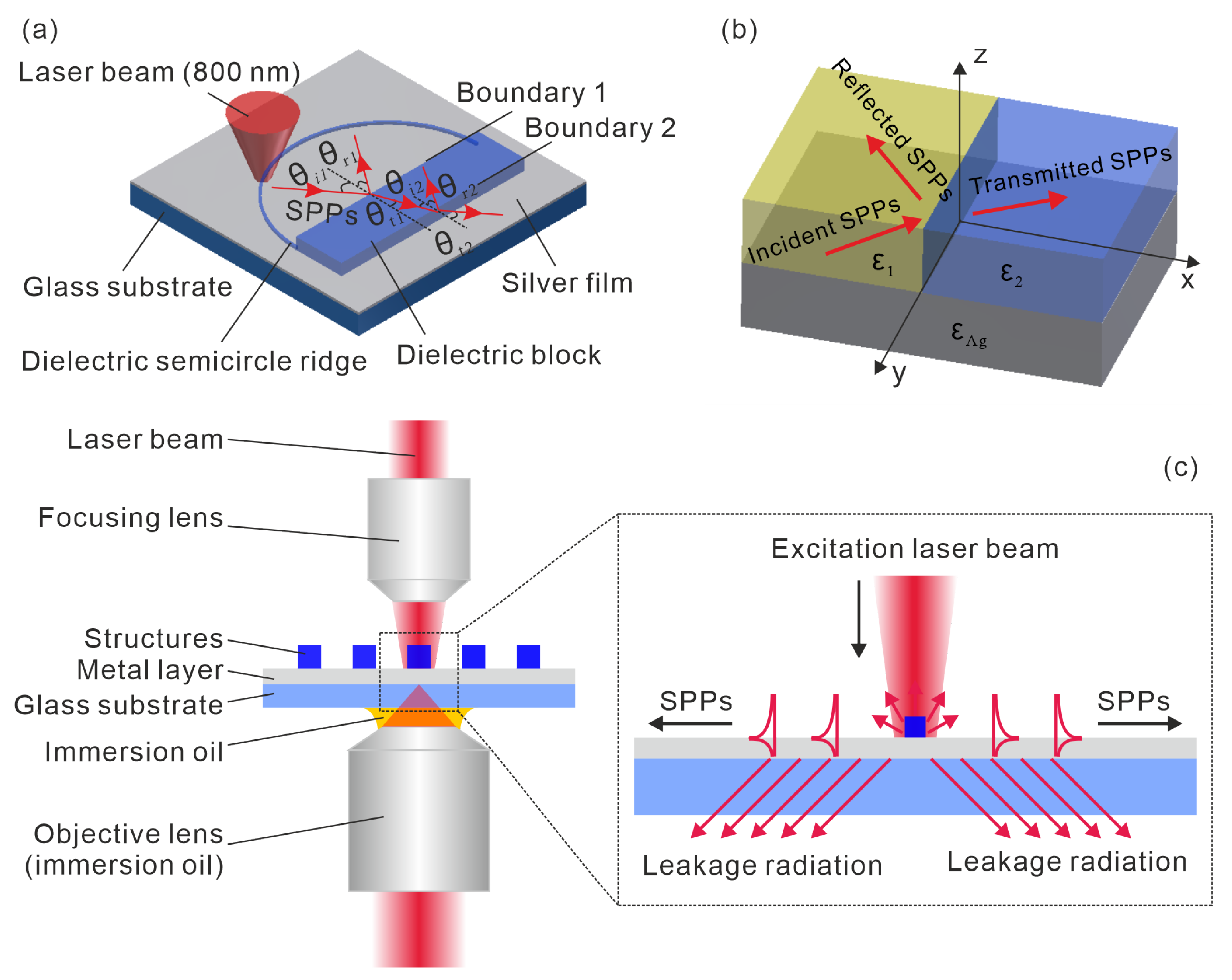
2. Theoretical Model

It is known that when a plane wave impinges onto a boundary between two homogeneous media with different dielectric constants, the plane wave can be split into a reflected wave and a transmitted wave, with the reflected wave propagating back to the first medium and the transmitted wave proceeding into the second medium [70]. The propagation directions of the reflected wave and the transmitted wave can be expressed using θ r = θ i (the law of reflection) and k t sin θ t = k i sin θ i (Snell’s law) [70], with θ i indicating the angle of incidence, θ r the angle of reflection and θ t the angle of transmission, k i the wave number of the incident light and k t the wave number of the transmitted light. Both laws are deduced from the boundary conditions, which have to be satisfied for the existence of the reflected and transmitted waves. Therefore, the reflection and transmission of surface plasmon polaritons (SPPs) have to fulfil the boundary conditions at the interface between isotropic media with different dielectric constants.
A geometrical illustration of the reflection and transmission of SPPs at the boundary of two homogeneous media with the dielectric constants ε 1 and ε 2 is presented in Figure 1b. In this work, the dielectric block is made of ma-N 1405, which is a commercially available photoresist from micro resist technology GmbH and has a dielectric constant ε 2 = 2.64 at the wavelength of 800 nm. The dielectric constant of air is ε 1 = 1 . With electromagnetic radiation at the wavelength λ = 800 nm, silver has the complex dielectric function ε A g = 30.33 + 0.81 i , which is calculated using the formula in the ref [11]. Here, we assume that the dielectric medium and Ag are in the region z > 0 and z < 0 , respectively. At boundary 1 (see Figure 1a), x = 0 . When SPPs propagate along the interface of Ag and a dielectric, the field of SPPs has a component e i ω t + i k x x + k y y in the interface plane and exhibits exponential decay away from the interface. The dispersion relations of SPPs can be expressed as [1,11]:
k s p p 1 = ω c ε 1 ε A g ε 1 + ε A g
k s p p 2 = ω c ε 2 ε A g ε 2 + ε A g
where k s p p 1 and k s p p 2 represent the wave number of SPPs at the interface of Ag/air and Ag/ma-N 1405, ω indicates the angular laser frequency and c is the light velocity in vacuum. The angles of reflection and transmission are more related to the real component of the wave vector rather than its imaginary part, therefore only the real component of k s p p is considered for the following calculation and discussion. Combining the above equations with the law of reflection and Snell’s law [70], the angles of reflection ( θ r 1 and θ r 2 ) and transmission ( θ t 1 and θ t 2 ) at boundaries 1 and 2 (see Figure 1a) can be written as:
At boundary 1 ( ε 1 ε 2 ),
θ r 1 = θ i 1 ,
θ t 1 = arcsin ε 1 ( ε 2 + ε A g ) ε 2 ( ε 1 + ε A g ) sin θ i 1 .
At boundary 2 ( ε 2 ε 1 ),
θ r 2 = arcsin ε 1 ε 2 + ε A g ε 2 ε 1 + ε A g sin θ i 1 ,
θ t 2 = arcsin ε 2 ε 1 + ε A g ε 1 ε 2 + ε A g sin θ i 2 = θ i 1 .

3. Results and Discussion

The proposed structures were fabricated by microscope projection photolithography (MPP). The commercial material ma-N 1405 (microresist technology GmbH) was employed for the fabrication. The refractive index of this material is approximately 1.625 at the wavelength of 800 nm. Figure 2 shows SEM images of fabricated structures obtained with an exposure time of 1000 ms. Structures with radii of r = 20 , 25, 30 and 40 μ m (see Figure 2) were fabricated, respectively. Smooth semicircle ridges and good surface quality dielectric blocks can be observed on each structure. With the exposure duration of 1000 ms, the height of the dielectric block is approximately 700 nm (Figure 2f).
When excited in the ridge, SPPs propagate along the radial direction at the boundary between Ag and air, with the wave vector k s p p 1 = ω c ε 1 ε A g ε 1 + ε A g . When striking onto the dielectric block, the transmitted wave proceeding into the dielectric then propagates at the interface between Ag and the dielectric, with k s p p 2 ω c ε 2 ε A g ε 2 + ε A g . The propagation lengths of SPPs along the interfaces of Ag/air and Ag/dielectric were calculated using L s p p = 1 2 k s p p [11]. They are approximately 140 μ m and 30 μ m at the wavelength of 800 nm, respectively. The length of 140 μ m is much greater than the obtained maximum radius of the semicircle (40 μ m), and 30 μ m is larger than the width of the dielectric block (10 μ m). Therefore, all the structures could be used for the investigation of the SPP propagation behavior. In this work, the structure with r = 40 μ m was employed for the experimental investigation for the purpose of ensuring better observation of SPPs in a relatively large space. By installing the sample into the leakage radiation microscopy (LRM) setup and focusing the laser beam onto the semicircle ridge, SPPs can be excited and propagate along the radial direction of the semicircle. Figure 3a is the LRM image of SPPs excited using the proposed structure. Surface plasmon polaritons are split into reflected wave and transmitted wave, when impinging onto the boundary between air and dielectric. The transmitted wave proceeds into the dielectric block and strikes onto boundary 2, where the wave propagates from a dense medium (dielectric) to a thin medium (air). In this case, the wave will be totally reflected when the incident angle θ i 2 θ c , with θ c = arcsin k s p p 1 k s p p 2 = 36.73 indicating the critical angle of total reflection. However, the total reflection does not occur at boundary 2, since the incident wave is exactly the transmitted wave at boundary 1, where SPPs proceed from air into the dielectric block. Based on Snell’s law, the angle of transmission θ t 1 , which equals the incident angle θ i 2 , can not exceed θ c . In the image plane (Figure 3a), the transmitted wave out of boundary 2 is visible, while the reflected wave and transmitted wave at boundary 1 are only weakly observable. Consequently, an observation of propagating SPPs in the Fourier plane (Figure 3b) was performed, on which the propagation directions of the waves can be more explicitly visualized.
By moving the laser focus onto different positions on the semicircle ridge, the incident angle of SPPs impinging onto boundary 1 can be controlled. Here the reflection and transmission of SPPs with the variation of the incident angle θ i 1 (in the range of 0–90 ) at both boundaries 1 and 2 were observed. Figure 4 presents the images (in the image plane) of SPP propagation with different incident angles. The intensity of SPPs is greatly reduced when the waves hit onto the dielectric block. The reflected waves at those two boundaries and the transmitted wave into the dielectric block are weakly visible. Their existence can only be identified in the Fourier plane. Nevertheless, the transmitted waves out of boundary 2 are always observable in the image plane. Also, an intensity variation of the transmitted wave with respect to θ i 1 can be seen. The angles of incidence ( θ i 1 ) and transmission ( θ t 1 and θ t 2 ) can be measured in the figures obtained in the image plane. Additionally, observations of propagating SPPs in the Fourier plane were also performed, from where the angles of reflection ( θ r 1 ) for different incident angles are measurable. Here, the angle of reflection at boundary 2 ( θ r 2 ) is not taken into consideration due to the invisibility of the corresponding reflected waves within most of the incident angle range. For the purpose of improving the measurement accuracy of those angles, multiple measurements of each single angle ( θ i 1 , θ r 1 , θ t 1 and θ t 2 ) under a fixed wave propagation direction were performed. An average of the multiply measured data for the same angle is taken as the experimental data point (see measured data in Figure 5). The measured data is presented together with an error bar, which is obtained based on the calculated standard deviation. Moreover, the variation of the angles of reflection and transmission with respect to the incident angle was also calculated analytically using Equations (3)–(6). The analytical and measured dependence of the angles of reflection and transmission on the incident angle is presented in Figure 5a indicating the results at boundary 1 and Figure 5b representing the results at boundary 2. Agreement between the analytical results and the experimental results is obtained. It has to be noted that the measurement error mainly results from the irregular form of the propagating SPP waves. Additionally, the weak light intensity for some directions might also affect the measurement results. Furthermore, it will be of significance to simulate and develop an effective approach to quantitatively characterize the intensity variation of propagating SPPs in the proposed structures for better control and optimization of their performance.

4. Conclusions

In conclusion, the reflection and transmission effects of SPPs at the boundaries between two different dielectrics are investigated. A special surface metallic structure with micrometer- and partially also nanometer-sized dimensions, which is composed of a dielectric semicircle ridge and a dielectric block, was designed and realized for this investigation. A microscope projection photolithography technique was applied for the fabrication of the proposed structures. The excitation of SPPs and experimental observations of their propagation behavior were realized using leakage radiation microscopy. The variation of the angles of reflection and transmission with respect to the angle of incidence was analytically estimated and experimentally measured. The validity of the law of reflection and Snell’s law in surface plasmon polaritons (SPPs) is confirmed. The integrated structures reported in this work might lay the foundations for novel applications in sensing when functionalized. This will be part of our future work which will aim at measuring the dependence of the SPP behaviors depending on the environmental conditions.

Author Contributions

L.Z., A.E. and C.R. planned the research concept, L.Z. designed the structures, L.Z. performed the experiments and investigations, U.Z. helped to manufacture the structures, L.Z. wrote the paper, A.E., B.R., L.O. and C.R. contributed to the discussion and revision of the manuscript.

Funding

This research was funded by the Deutsche Forschungsgemeinschaft (DFG) under Germany’s Excellence Strategy within the Cluster of Excellence PhoenixD (EXC 2122, Project ID 390833453) and the DFG (German Research Foundation, Project ID RE3012/4-1 and RE3012/2-1). The publication of this article was funded by the Open Access Fund of the Leibniz Universität Hannover.

Conflicts of Interest

The authors declare no conflict of interest.

Abbreviations

The following abbreviations are used in this manuscript:
SPPsSurface plasmon polaritons
MPPMicroscope projection photolithography
LRMLeakage radiation microscopy

References

  1. Raether, H. Surface Plasmons on Smooth Surfaces; Springer: Berlin, Germany, 1988. [Google Scholar]
  2. Stegeman, G.; Maradudin, A.; Rahman, T. Refraction of a surface polariton by an interface. Phys. Rev. B 1981, 23, 2576. [Google Scholar] [CrossRef]
  3. Stegeman, G.I.; Glass, N.; Maradudin, A.A.; Shen, T.; Wallis, R. Fresnel relations for surface polaritons at interfaces. Opt. Lett. 1983, 8, 626–628. [Google Scholar] [CrossRef] [PubMed]
  4. Otto, A. Excitation of nonradiative surface plasma waves in silver by the method of frustrated total reflection. Zeitschrift für Physik A Hadrons Nuclei 1968, 216, 398–410. [Google Scholar] [CrossRef]
  5. Kretschmann, E.; Raether, H. Radiative decay of non radiative surface plasmons excited by light. Zeitschrift für Naturforschung A 1968, 23, 2135–2136. [Google Scholar] [CrossRef]
  6. Hecht, B.; Bielefeldt, H.; Novotny, L.; Inouye, Y.; Pohl, D. Local excitation, scattering, and interference of surface plasmons. Phys. Rev. Lett. 1996, 77, 1889. [Google Scholar] [CrossRef]
  7. Bouhelier, A.; Huser, T.; Tamaru, H.; Güntherodt, H.J.; Pohl, D.; Baida, F.I.; Van Labeke, D. Plasmon optics of structured silver films. Phys. Rev. B 2001, 63, 155404. [Google Scholar] [CrossRef]
  8. Devaux, E.; Ebbesen, T.W.; Weeber, J.C.; Dereux, A. Launching and decoupling surface plasmons via micro-gratings. Appl. Phys. Lett. 2003, 83, 4936–4938. [Google Scholar] [CrossRef]
  9. Park, S.; Lee, G.; Song, S.H.; Oh, C.H.; Kim, P.S. Resonant coupling of surface plasmons to radiation modes by use of dielectric gratings. Opt. Lett. 2003, 28, 1870–1872. [Google Scholar] [CrossRef]
  10. Koev, S.T.; Agrawal, A.; Lezec, H.J.; Aksyuk, V.A. An efficient large-area grating coupler for surface plasmon polaritons. Plasmonics 2012, 7, 269–277. [Google Scholar] [CrossRef]
  11. Le Ru, E.; Etchegoin, P. Principles of Surface-Enhanced Raman Spectroscopy: And Related Plasmonic Effects; Elsevier: Amsterdam, The Netherlands, 2008. [Google Scholar]
  12. Salomon, L.; Bassou, G.; Aourag, H.; Dufour, J.; De Fornel, F.; Carcenac, F.; Zayats, A. Local excitation of surface plasmon polaritons at discontinuities of a metal film: Theoretical analysis and optical near-field measurements. Phys. Rev. B 2002, 65, 125409. [Google Scholar] [CrossRef]
  13. Inampudi, S.; Mosallaei, H. Fresnel refraction and diffraction of surface plasmon polaritons in two-dimensional conducting sheets. ACS Omega 2016, 1, 843–853. [Google Scholar] [CrossRef] [PubMed]
  14. Zia, R.; Schuller, J.A.; Chandran, A.; Brongersma, M.L. Plasmonics: The next chip-scale technology. Mater. Today 2006, 9, 20–27. [Google Scholar] [CrossRef]
  15. Ozbay, E. Plasmonics: Merging photonics and electronics at nanoscale dimensions. Science 2006, 311, 189–193. [Google Scholar] [CrossRef] [PubMed]
  16. Anker, J.N.; Hall, W.P.; Lyandres, O.; Shah, N.C.; Zhao, J.; Van Duyne, R.P. Biosensing with plasmonic nanosensors. Nat. Mater. 2008, 7, 442–453. [Google Scholar] [CrossRef] [PubMed]
  17. Homola, J. Surface plasmon resonance sensors for detection of chemical and biological species. Chem. Rev. 2008, 108, 462–493. [Google Scholar] [CrossRef]
  18. McMahon, J.M.; Henzie, J.; Odom, T.W.; Schatz, G.C.; Gray, S.K. Tailoring the sensing capabilities of nanohole arrays in gold films with Rayleigh anomaly-surface plasmon polaritons. Opt. Express 2007, 15, 18119–18129. [Google Scholar] [CrossRef] [Green Version]
  19. Swiontek, S.E.; Pulsifer, D.P.; Lakhtakia, A. Optical sensing of analytes in aqueous solutions with a multiple surface-plasmon-polariton-wave platform. Sci. Rep. 2013, 3, 1409. [Google Scholar] [CrossRef] [Green Version]
  20. Salerno, M.; Krenn, J.R.; Lamprecht, B.; Schider, G.; Ditlbacher, H.; Félidj, N.; Leitner, A.; Aussenegg, F.R. Plasmon polaritons in metal nanostructures: The optoelectronic route to nanotechnology. Optoelectron. Rev. 2002, 3, 217–224. [Google Scholar]
  21. Zhang, J.; Zhang, L.; Xu, W. Surface plasmon polaritons: Physics and applications. J. Phys. D Appl. Phys. 2012, 45, 113001. [Google Scholar] [CrossRef]
  22. Wang, T.B.; Wen, X.W.; Yin, C.P.; Wang, H.Z. The transmission characteristics of surface plasmon polaritons in ring resonator. Opt. Express 2009, 17, 24096–24101. [Google Scholar] [CrossRef]
  23. Luo, X.; Ishihara, T. Surface plasmon resonant interference nanolithography technique. Appl. Phys. Lett. 2004, 84, 4780–4782. [Google Scholar] [CrossRef]
  24. Liu, Z.W.; Wei, Q.H.; Zhang, X. Surface plasmon interference nanolithography. Nano Lett. 2005, 5, 957–961. [Google Scholar] [CrossRef] [PubMed]
  25. Srituravanich, W.; Fang, N.; Sun, C.; Luo, Q.; Zhang, X. Plasmonic nanolithography. Nano Lett. 2004, 4, 1085–1088. [Google Scholar] [CrossRef]
  26. Srituravanich, W.; Pan, L.; Wang, Y.; Sun, C.; Bogy, D.B.; Zhang, X. Flying plasmonic lens in the near field for high-speed nanolithography. Nat. Nanotechnol. 2008, 3, 733. [Google Scholar] [CrossRef] [PubMed]
  27. Xie, Z.; Yu, W.; Wang, T.; Zhang, H.; Fu, Y.; Liu, H.; Li, F.; Lu, Z.; Sun, Q. Plasmonic nanolithography: A review. Plasmonics 2011, 6, 565. [Google Scholar] [CrossRef]
  28. Liu, H.; Teng, J. Plasmonic nanolithography: towards next generation nanopatterning. J. Mol. Eng. Mater. 2013, 1, 1250005. [Google Scholar] [CrossRef]
  29. Reinhardt, C.; Kiyan, R.; Seidel, A.; Passinger, S.; Stepanov, A.L.; Evlyukhin, A.B.; Chichkov, B.N. Focusing and manipulation of surface plasmon polaritons by laser fabricated dielectric structures. In Plasmonics: Nanoimaging, Nanofabrication, and Their Applications III; International Society for Optics and Photonics: Bellingham, WA, USA, 2007; Volume 6642, p. 664205. [Google Scholar]
  30. Verhagen, E.; Polman, A.; Kuipers, L.K. Nanofocusing in laterally tapered plasmonic waveguides. Opt. Express 2008, 16, 45–57. [Google Scholar] [CrossRef]
  31. Luo, Y.; Chamanzar, M.; Apuzzo, A.; Salas-Montiel, R.; Nguyen, K.N.; Blaize, S.; Adibi, A. On-chip hybrid photonic–plasmonic light concentrator for nanofocusing in an integrated silicon photonics platform. Nano Lett. 2015, 15, 849–856. [Google Scholar] [CrossRef]
  32. Alaoui, M.; Rustomji, K.; Chang, T.; Tayeb, G.; Sabouroux, P.; Quidant, R.; Enoch, S.; Guenneau, S.; Abdeddaim, R. Cyclic concentrator, carpet cloaks and fisheye lens via transformation plasmonics. J. Opt. 2016, 18, 044023. [Google Scholar] [CrossRef]
  33. Stockman, M.I. Nanofocusing of optical energy in tapered plasmonic waveguides. Phys. Rev. Lett. 2004, 93, 137404. [Google Scholar] [CrossRef]
  34. Smolyaninov, I.I.; Hung, Y.J.; Davis, C.C. Surface plasmon dielectric waveguides. Appl. Phys. Lett. 2005, 87, 241106. [Google Scholar] [CrossRef] [Green Version]
  35. Oulton, R.F.; Sorger, V.J.; Genov, D.; Pile, D.; Zhang, X. A hybrid plasmonic waveguide for subwavelength confinement and long-range propagation. Nat. Photonics 2008, 2, 496–500. [Google Scholar] [CrossRef] [Green Version]
  36. Lu, H.; Gan, X.; Mao, D.; Zhao, J. Graphene-supported manipulation of surface plasmon polaritons in metallic nanowaveguides. Photonics Res. 2017, 5, 162–167. [Google Scholar] [CrossRef]
  37. Liu, Z.; Steele, J.M.; Srituravanich, W.; Pikus, Y.; Sun, C.; Zhang, X. Focusing surface plasmons with a plasmonic lens. Nano Lett. 2005, 5, 1726–1729. [Google Scholar] [CrossRef] [PubMed]
  38. Zentgraf, T.; Liu, Y.; Mikkelsen, M.H.; Valentine, J.; Zhang, X. Plasmonic luneburg and eaton lenses. Nat. Nanotechnol. 2011, 6, 151. [Google Scholar] [CrossRef] [PubMed]
  39. Aieta, F.; Genevet, P.; Kats, M.A.; Yu, N.; Blanchard, R.; Gaburro, Z.; Capasso, F. Aberration-free ultrathin flat lenses and axicons at telecom wavelengths based on plasmonic metasurfaces. Nano Lett. 2012, 12, 4932–4936. [Google Scholar] [CrossRef]
  40. Shackleford, J.A.; Grote, R.; Currie, M.; Spanier, J.E.; Nabet, B. Integrated plasmonic lens photodetector. Appl. Phys. Lett. 2009, 94, 083501. [Google Scholar] [CrossRef]
  41. Kim, J.T.; Yu, Y.J.; Choi, H.; Choi, C.G. Graphene-based plasmonic photodetector for photonic integrated circuits. Opt. Express 2014, 22, 803–808. [Google Scholar] [CrossRef]
  42. Mousavi, S.S.; Stöhr, A.; Berini, P. Plasmonic photodetector with terahertz electrical bandwidth. Appl. Phys. Lett. 2014, 104, 143112. [Google Scholar] [CrossRef]
  43. Harrer, A.; Schwarz, B.; Gansch, R.; Reininger, P.; Detz, H.; Zederbauer, T.; Andrews, A.M.; Schrenk, W.; Strasser, G. Plasmonic lens enhanced mid-infrared quantum cascade detector. Appl. Phys. Lett. 2014, 105, 171112. [Google Scholar] [CrossRef]
  44. Levy, U.; Grajower, M.; Goncalves, P.; Mortensen, N.A.; Khurgin, J.B. Plasmonic silicon Schottky photodetectors: The physics behind graphene enhanced internal photoemission. Apl Photonics 2017, 2, 026103. [Google Scholar] [CrossRef] [Green Version]
  45. Clavero, C.; Yang, K.; Skuza, J.; Lukaszew, R. Magnetic field modulation of intense surface plasmon polaritons. Opt. Express 2010, 18, 7743–7752. [Google Scholar] [CrossRef] [PubMed]
  46. Ignatyeva, D.O.; Knyazev, G.A.; Kapralov, P.O.; Dietler, G.; Sekatskii, S.K.; Belotelov, V.I. Magneto-optical plasmonic heterostructure with ultranarrow resonance for sensing applications. Sci. Rep. 2016, 6, 28077. [Google Scholar] [CrossRef] [PubMed]
  47. Li, Z.; Sun, Y.; Wang, K.; Song, J.; Shi, J.; Gu, C.; Liu, L.; Luo, Y. Tuning the dispersion of effective surface plasmon polaritons with multilayer systems. Opt. Express 2018, 26, 4686–4697. [Google Scholar] [CrossRef]
  48. Zouhdi, S.; Sihvola, A.; Vinogradov, A.P. Metamaterials and Plasmonics: Fundamentals, Modelling, Applications; Springer Science & Business Media: Berlin, Germany, 2008. [Google Scholar]
  49. Ju, L.; Geng, B.; Horng, J.; Girit, C.; Martin, M.; Hao, Z.; Bechtel, H.A.; Liang, X.; Zettl, A.; Shen, Y.R.; et al. Graphene plasmonics for tunable terahertz metamaterials. Nat. Nanotechnol. 2011, 6, 630. [Google Scholar] [CrossRef]
  50. Luk’yanchuk, B.; Zheludev, N.I.; Maier, S.A.; Halas, N.J.; Nordlander, P.; Giessen, H.; Chong, C.T. The Fano resonance in plasmonic nanostructures and metamaterials. Nat. Mater. 2010, 9, 707. [Google Scholar] [CrossRef]
  51. Kabashin, A.; Evans, P.; Pastkovsky, S.; Hendren, W.; Wurtz, G.; Atkinson, R.; Pollard, R.; Podolskiy, V.; Zayats, A. Plasmonic nanorod metamaterials for biosensing. Nat. Mater. 2009, 8, 867–871. [Google Scholar] [CrossRef]
  52. Papari, G.P.; Koral, C.; Andreone, A. Geometrical Dependence on the Onset of Surface Plasmon Polaritons in THz Grid Metasurfaces. Sci. Rep. 2019, 9, 924. [Google Scholar] [CrossRef]
  53. Liu, J.; Fang, G.; Zhao, H.; Zhang, Y.; Liu, S. Surface plasmon reflector based on serial stub structure. Opt. Express 2009, 17, 20134–20139. [Google Scholar] [CrossRef]
  54. Hosseini, A.; Massoud, Y. A low-loss metal-insulator-metal plasmonic bragg reflector. Opt. Express 2006, 14, 11318–11323. [Google Scholar] [CrossRef]
  55. Xu, T.; Wang, C.; Du, C.; Luo, X. Plasmonic beam deflector. Opt. Express 2008, 16, 4753–4759. [Google Scholar] [CrossRef] [PubMed]
  56. Wu, W.; Yang, J.; Chen, D. Plasmonic Beam Deflector and Optical Coupler. IEEE Photonics Technol. Lett. 2017, 29, 1592–1595. [Google Scholar] [CrossRef]
  57. Schuller, J.A.; Barnard, E.S.; Cai, W.; Jun, Y.C.; White, J.S.; Brongersma, M.L. Plasmonics for extreme light concentration and manipulation. Nat. Mater. 2010, 9, 193–204. [Google Scholar] [CrossRef] [PubMed]
  58. MacDonald, K.F.; Zheludev, N.I. Active plasmonics: Current status. Laser Photonics Rev. 2010, 4, 562–567. [Google Scholar] [CrossRef]
  59. Voronko, A.; Klimova, L.; Shkerdin, G. Reflection of surface polaritons at a dielectric barrier. Solid State Commun. 1987, 61, 361–364. [Google Scholar] [CrossRef]
  60. Oulton, R.F.; Pile, D.F.; Liu, Y.; Zhang, X. Scattering of surface plasmon polaritons at abrupt surface interfaces: Implications for nanoscale cavities. Phys. Rev. B 2007, 76, 035408. [Google Scholar] [CrossRef] [Green Version]
  61. Elser, J.; Podolskiy, V.A. Scattering-free plasmonic optics with anisotropic metamaterials. Phys. Rev. Lett. 2008, 100, 066402. [Google Scholar] [CrossRef]
  62. Váry, T.; Markoš, P. Propagation of surface plasmons through planar interface. In Metamaterials IV; International Society for Optics and Photonics: Bellingham, WA, USA, 2009; Volume 7353, p. 73530K. [Google Scholar]
  63. Radko, I.P.; Volkov, V.S.; Beermann, J.; Evlyukhin, A.B.; Søndergaard, T.; Boltasseva, A.; Bozhevolnyi, S.I. Plasmonic metasurfaces for waveguiding and field enhancement. Laser Photonics Rev. 2009, 3, 575–590. [Google Scholar] [CrossRef]
  64. Evlyukhin, A.B.; Reinhardt, C.; Evlyukhina, E.; Chichkov, B.N. Asymmetric and symmetric local surface-plasmon-polariton excitation on chains of nanoparticles. Opt. Lett. 2009, 34, 2237–2239. [Google Scholar] [CrossRef]
  65. Gerasimov, V.V.; Knyazev, B.A.; Nikitin, A.K. Reflection of terahertz monochromatic surface plasmon-polaritons by a plane mirror. Quantum Electron. 2017, 47, 65. [Google Scholar] [CrossRef]
  66. Zon, V.B. Reflection, refraction, and transformation into photons of surface plasmons on a metal wedge. JOSA B 2007, 24, 1960–1967. [Google Scholar] [CrossRef]
  67. Radko, I.P.; Evlyukhin, A.B.; Boltasseva, A.; Bozhevolnyi, S.I. Refracting surface plasmon polaritons with nanoparticle arrays. Opt. Express 2008, 16, 3924–3930. [Google Scholar] [CrossRef] [PubMed]
  68. Love, J.C.; Wolfe, D.B.; Jacobs, H.O.; Whitesides, G.M. Microscope projection photolithography for rapid prototyping of masters with micron-scale features for use in soft lithography. Langmuir 2001, 17, 6005–6012. [Google Scholar] [CrossRef]
  69. Zheng, L.; Evlyukhin, A.; Overmeyer, L.; Reinhardt, C. Omnidirectional Surface Plasmon Polaritons Concentration in 3D Metallic Structures. Plasmonics 2019. [Google Scholar] [CrossRef]
  70. Born, M.; Wolf, E. Principles of Optics: Electromagnetic Theory of Propagation, Interference and Diffraction of Light; Elsevier: Amsterdam, The Netherlands, 2013. [Google Scholar]
Figure 1. Geometrical illustrations. (a) Geometrical representation of the proposed structure. (b) Schematic illustration of reflection and transmission of surface plasmon polaritons (SPPs) at the interface of two different homogeneous dielectrics. (c) Schematic illustration of generating SPPs by surface defects and visualization principle of propagating SPPs through leakage radiation microscopy (LRM). A detailed description of LRM can be found in ref [69].
Sensors 19 04633 g001
Figure 2. SEM images of the structures fabricated by MPP. (a,b) SEM images of four structures with different dimensions. (c) SEM image of the structure with the radius of curvature r = 20 μ m. (d) SEM image of the structure with r = 30 μ m. (e) SEM image of the structure with r = 40 μ m. (f) The magnified SEM image of the dielectric block.SEM images of the structures fabricated by microscope projection photolithography (MPP)
Sensors 19 04633 g002
Figure 3. LRM images of the reflection and transmission of SPPs at the boundary of air and the dielectric. The angles of incidence, reflection and transmission, respectively, are indicated by θ i 1 , θ r 1 , θ t 1 at boundary 1 and θ i 2 ( θ i 2 = θ t 1 ), θ r 2 , θ t 2 at boundary 2. (a) Observed image in the image plane. (b) Observed image in the Fourier plane.
Sensors 19 04633 g003
Figure 4. LRM images of the reflection and transmission of SPP waves at the air/dielectric boundary depending on the angle of incidence. The range of the angle of incidence is between 0 and 90 .
Sensors 19 04633 g004
Figure 5. Calculation and experimental measurement of the angles of transmission and reflection with respect to the incident angle. The measurement error of incident angles is within ± 2.5 . (a) The calculated and measured angles of transmission and reflection at boundary 1. The indications, the blue line (): calculated θ r 1 , the blue symbol (): measured θ r 1 , the red line (): calculated θ t 1 , the red symbol (): measured θ t 1 . (b) The calculated and measured angle of transmission at boundary 2. The indications, the red line (): calculated θ t 2 , the red symbol (): measured θ t 2 .
Sensors 19 04633 g005

