1. Introduction
With the rapid advancement of artificial intelligence, robots are playing an increasingly important role in both industry and daily routines [
1]. More and more robots are being developed and widely deployed to undertake various jobs that had been fulfilled manually before [
2,
3]. For example, in modern libraries, mobile robots are being employed to fulfill the tedious yet simple book accessing and returning (BAR) tasks [
4,
5]. To enable such high-precision functions, however, numerous technologies (e.g., sensing, actuation, manipulation, locomotion, environmental interaction, positioning and navigation (P&N), and human-robot interaction) are involved. Among all those required technologies, the indoor robot P&N technologies are the key factors in determining the accuracies of robot movements, book identification, and accessing and returning operations.
The current navigation technologies typically include satellite navigation, magnetic navigation, sensor navigation, inertial navigation, and visual navigation [
6,
7]. Satellite and magnetic navigation technologies are two conventional ways of navigation, yet are seldom utilized for indoor P&Ns. This is because the satellite signals can not penetrate through the buildings, while the magnetic navigation guide lines are expensive and difficult to expand or replace once located [
8]. Sensor navigation, including infrared, laser, and ultrasound navigation, are typically based on nonvisual sensors to measure the transmitting and reflecting signals from the objects. Owing to their limited navigation accuracies, navigation distances, and high prices, sensor navigation is commonly adopted for military purposes [
9,
10]. Inertial navigation is a sophisticated way for autonomous navigation without relying on any external information. However, its cost is high and it also requires a large amount of time for calibration before use, due to the influences of the accumulated navigation errors [
11]. Vision navigation, including monocular vision, binocular vision, and multi-vision, is based on camera systems to collect surrounding information to establish environment maps for P&Ns [
12]. Due to the limited field of view (FOV) of the cameras, however, vision navigation suffers from a lack of accuracy in large distance positioning, and it is typically utilized for indoor navigation [
13,
14].
To address the limited accuracy issues with these existing navigation technologies, new schemes—simultaneously utilizing two or more existing navigation technologies—have been proposed in the literature [
11,
15,
16,
17,
18,
19]. Based on integrated inertial and binocular vision navigation technologies, Wang et al. proposed a global map generation method to tackle the difficulties in indoor navigation map constructions [
16]. While by utilizing the simultaneous vision positioning and indoor map construction technologies to generate real-time incremental maps, authors in [
17] showed that the accumulated navigation system errors could be reduced effectively. Recently, Wang et al. adopted a visual odometer [
17,
18] to achieve unmanned aerial vehicle (UAV) positioning based on the visual optical flow information and inertial sensing data [
19]. However, it is worth noting that the amount of data to be processed with the integrated visual and inertial navigation technologies is huge, which thus limits the accuracy of the library digital maps generated for real-time applications.
To further improve the digital map accuracy while reducing the computational load, quick response (QR) code-based technology has also been introduced for mobile robot P&Ns [
20,
21,
22,
23]. QR codes are well-known for their low cost, large data storage, robustness against damages, and easy productivity/readability, etc., and they have been widely deployed in various cases in recent years. Eimon et al. pioneered the research by utilizing QR codes as personal identification tags and developed a human-tracking robot for services in public places like airports or supermarkets [
20]. Later, Suriyon et al. proposed to utilize QR codes as landmarks for a visitor guide robot traversing between two specified locations [
23], and Zhang et al. implemented an indoor mobile robot localization and navigation mechanism by utilizing QR codes to provide global location information and robot pose references [
21]. However, it is worth noting that all these developed robots either have only fixed targets or could only traverse between fixed locations without route re-planning functions, even though obstacles may block the robot trajectory occasionally in indoor environment. Furthermore, due to the limited FOV of the QR code scanners, those robots may also suffer from certain practical issues, such as the rediscovery issue in case of object missing, the QR code running outside issue at turning points, QR code access issues caused by light/sheltering conditions, and so on. Although some of those issues can be addressed by faster QR code scanners [
22], effective mechanisms are still needed for the ever-increasing high-precision mobile robot applications.
To benefit from the advantages of both binocular vision navigation and QR code identification technologies, we propose, for the first time (to the best of our knowledge), to integrate these two technologies together to improve the mobile robot P&N accuracies, and also construct an autonomous robot to implement the high-precision BAR operations, based on such a technology combination. In this paper, the binocular vision system is utilized to fulfill the rapid QR code region localization, dynamic digital map construction, autonomous robot P&N, as well as obstacle identification and avoiding functions. While the QR code identification technique is used to identify those QR code labels, and then access their contents for both robot operational error eliminations and robotic arm BAR operation calculations. With those two technologies working together, the robot is able to establish a high-precision library digital map, and then identify and avoid those obstacles to fulfil the real-time autonomous route-planning functions. Meanwhile, by accessing the QR code labels, it is also able to update the digital map frequently to eliminate the errors accumulated during its P&N process and, thus, realize the high-precision BAR operations. Both simulations and experiments have been conducted to verify the effectiveness of such a technology combination and the robot functionalities in different cases.
The remainder of this paper is organized as follows.
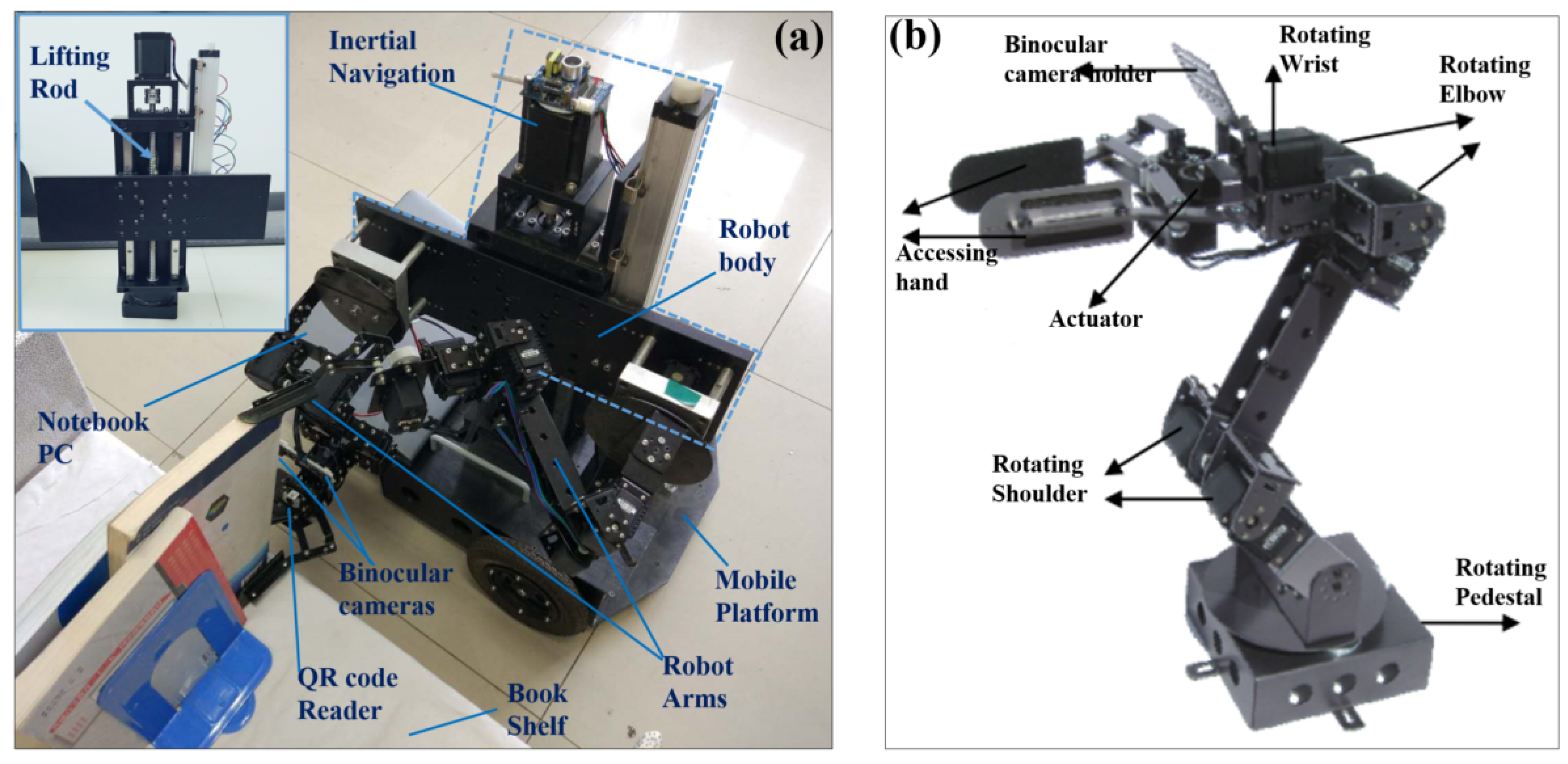
Section 2 presents the robot structure design and its binocular vision system.
Section 3 describes the proposed binocular vision and QR code identification technology integration based robot P&N and BAR operation mechanisms.
Section 4 presents the experiments conducted for mechanism and system verifications, and
Section 5 concludes the paper.
3. Library Robot P & N and BAR Mechanism
Compared to the structure design, the mechanism implementation for robot P&N and BAR operations is more complicated. This is because such a mechanism consists of many other functional sub-mechanisms; that is, the real-time robot route planning algorithm, the QR-code feature extraction and identification (QR-FEI) algorithm, and the QR-code based positioning accuracy correction algorithm, as well as the robot BAR operation algorithm. Each of those mechanisms will be described below.
3.1. Real-Time Robot Route Planning
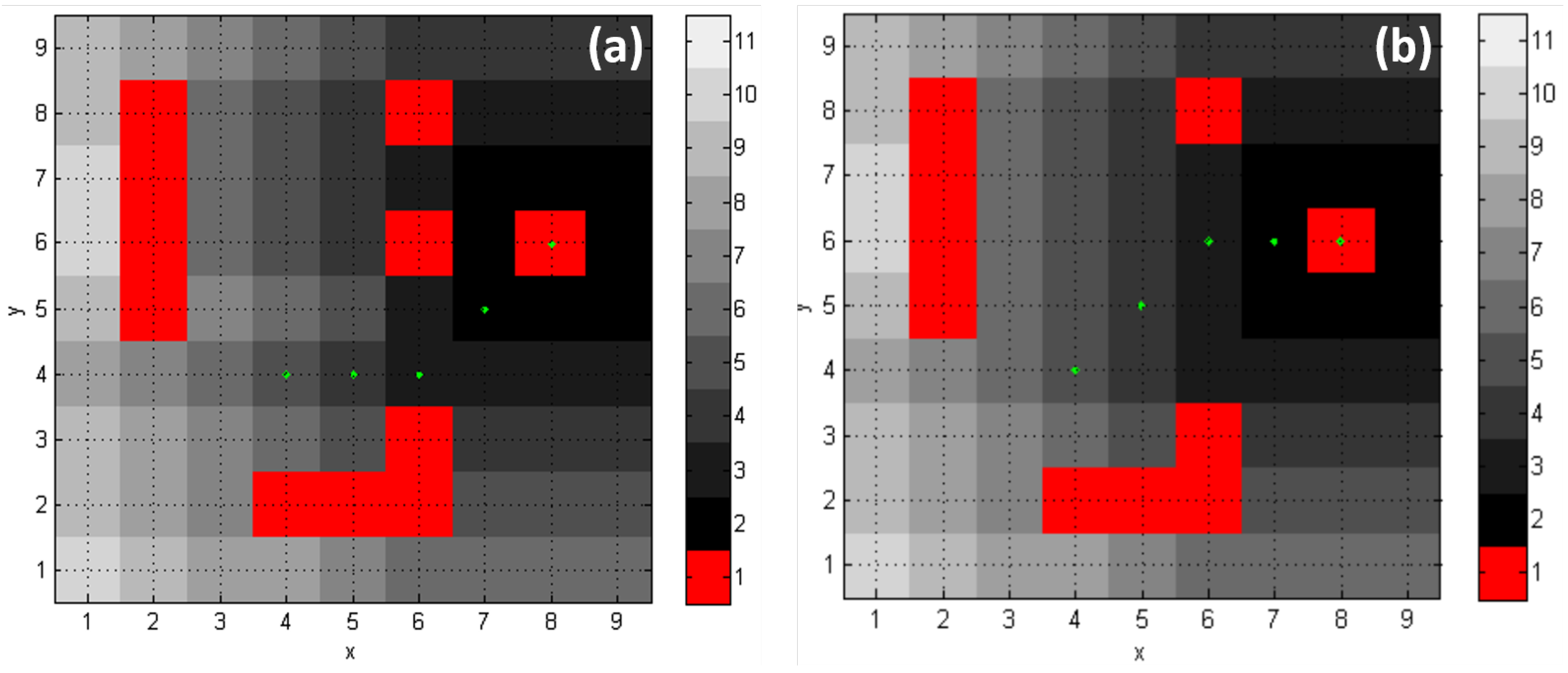
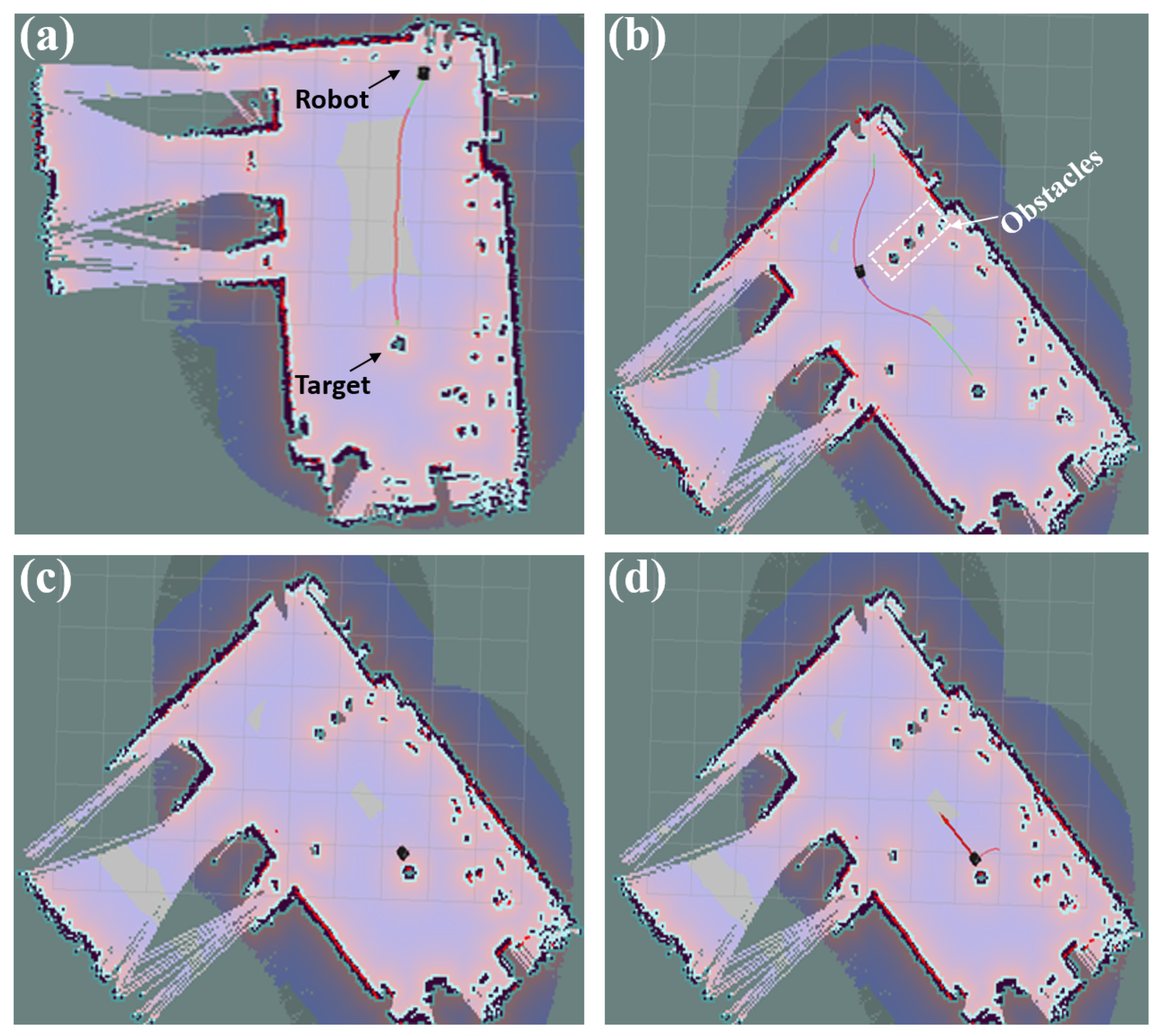
Once given the target, the library robot would start to navigate along the calculated shortest route to it. In practice, however, as the obstacles in libraries are usually distributed randomly and sometimes may even appear suddenly and block the robot trajectory, the robot has to perform real-time route planning. Such a function helps the robot find the shortest path to the target, and also avoid those obstacles. In this study, the improved
Lite algorithm, which supports incremental re-planning, is adopted for real-time robot route planning [
26,
27,
28].
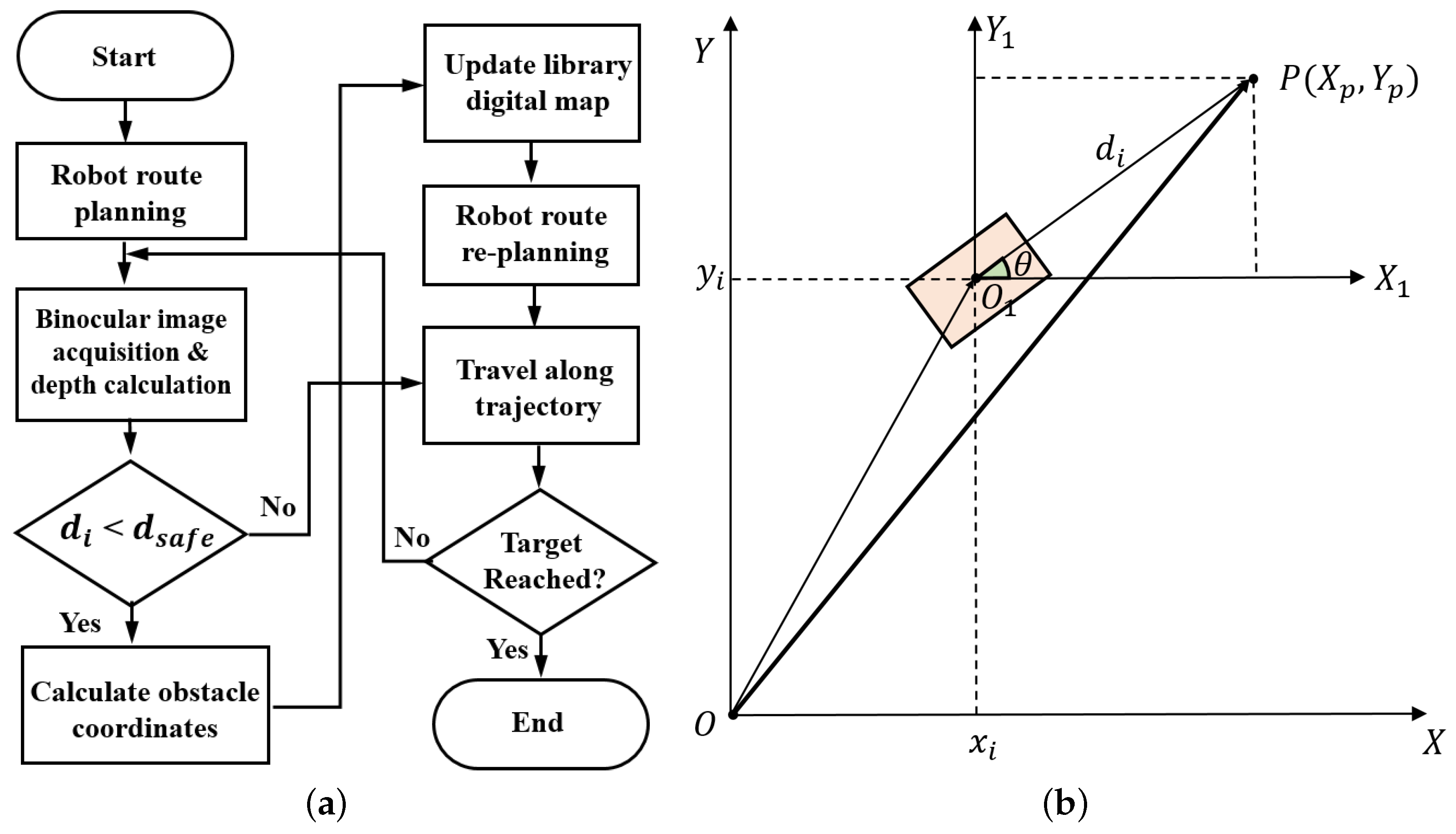
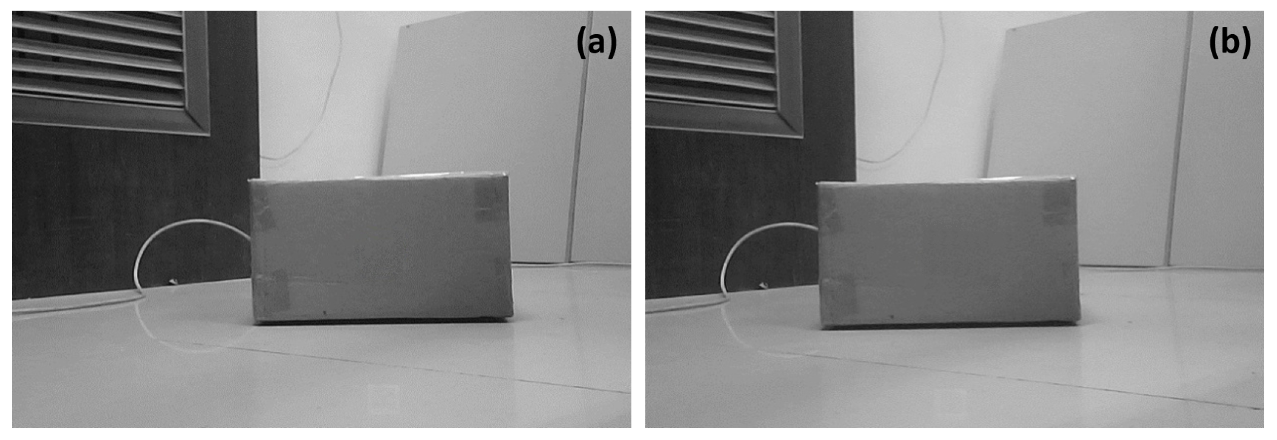
Figure 4a presents the binocular vision system imaging-based robot real-time route planning mechanism. When navigating to the target, the robot would acquire images along its trajectory periodically with the binocular vision system, and then calculate a depth value
immediately based upon its binocular vision system parallax. Such a
value is finally compared to a predefined threshold
to determine whether there is any obstacle along the route or not. When
is larger than
, it is assume that there is no obstacle and the robot keeps moving along its trajectory, while if
is smaller than
, it is assumed that obstacles are detected in the robot trajectory, and the shortest robot trajectory should be recalculated. In such a case, position information of the detected obstacles in library base coordinate system has to be calculated and remapped back to the library grid map.
Assume that the library base coordinate system in 2D plane is
and the robot 2D coordinate system is
, while the position of an obstacle
P in
is
, as shown in
Figure 4b. Once a depth value
is smaller than
for the robot at a position
, the obstacle position
P in the base coordinate system (i.e.,
), has to be calculated as follows,
where
and
as shown in
Figure 4b.
The position of
P in library grid map could be obtained using the equation below,
where
are arrays, while
is the function utilized to remap the position
from base coordinate to grid map and is given by Equation (
4) in
Section 2.2.
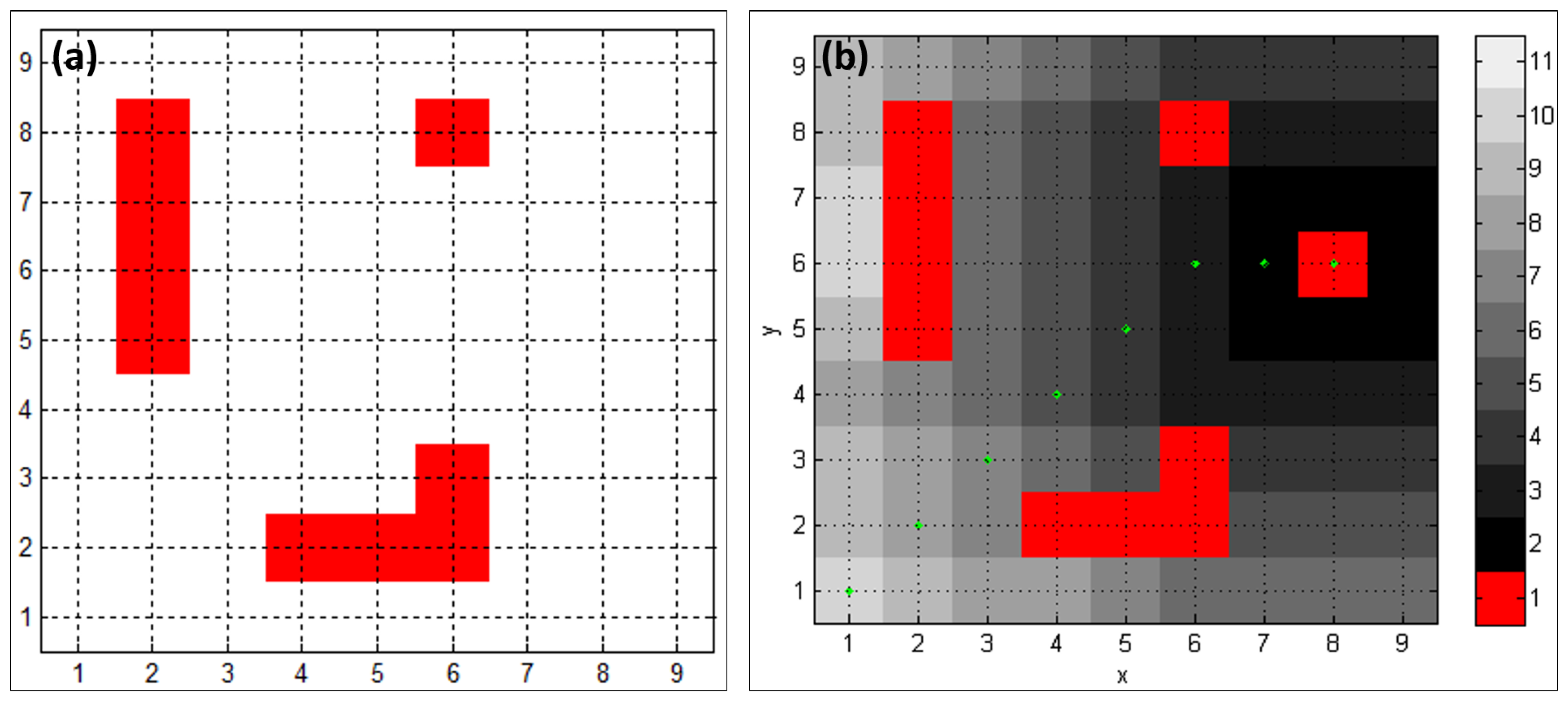
Therefore, once is obtained, the elements are updated with to denote that those positions in the library grid map are occupied by obstacles, and then the improved Lite algorithm is adopted to re-compute a shortest route for the robot. The main working steps of such a route planning mechanism are shown in Algorithm 1, wherein the Dijkstra’s shortest path algorithm could be modified to compute the shortest path between any two positions in the grid map. To achieve a balance between the computation load and the navigation accuracy, the camera image acquisition period was set to be 50 ms in this study. Such a period guarantees that once an obstacle is detected, the robot is able to perform real-time re-routing in time to avoid it.
| Algorithm 1 The improved Lite algorithm for real-time robot route planning. |
| Input: Target location , Robot starting point , Library grid map M. |
| Output: Planned trajectory for library robot. 1.8 |
| 1: Initialization. ; ; |
| 2: = Computeshortestpath(M, , ); |
| 3: while do |
| 4: ; |
| 5: Move to ; |
| 6: Scan library grid map M for changed edge costs; |
| 7: if any edge costs changed then |
| 8: update grid map M according Equation (8); |
| 9: ; |
| 10: ; |
| 11: for all directed edges with changed edge costs do |
| 12: updated the edge cost ; |
| 13: = Computeshortestpath(M, , ); |
| 14: end for |
| 15: end if |
| 16: end while |
| 17: Return robot trajectory . |
3.2. The QR-FEI Algorithm
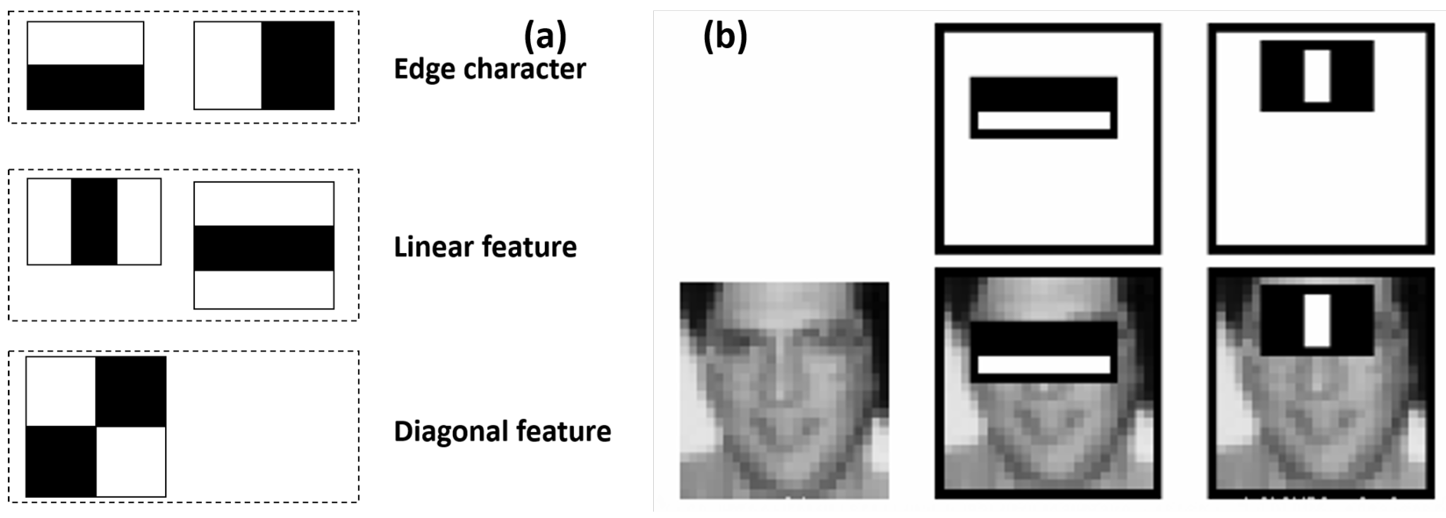
The Haar-like feature, which is group of characteristics consisting mainly of the edge, line, point, and diagonal features, as shown in
Figure 5a [
29], was adopted for the QR code identifications in this study. To denote an object, such a feature is typically made up of at least two rectangles, as shown in
Figure 5b, and its value is the difference between the sums of the pixel values within the black and white rectangles.
Owing to its reduced computational complexity and improved operating speed, the Viola-Jones integral graph algorithm [
30] was adopted for QR code Haar-like feature extraction in this study. Hence, for an image
i, its integral graph
at location of a point
contains the sum of the pixel values above and left of this pixel
(i.e., the upper left corner of
), and its feature value could be calculated as shown in Equation (
9).
When detecting the target QR codes, the image is scanned by a sub-window that contains a specific Haar-like feature as shown in
Figure 5b. Based on each Haar-like feature,
, the corresponding classifier
is given by Equation (
10) below,
where
x is the sample within the sub-window,
is the value of the
i-th Haar feature
of the sample
x,
is the symbol of classification direction,
is the classifier made up of features
, and
is the threshold of classifier
.
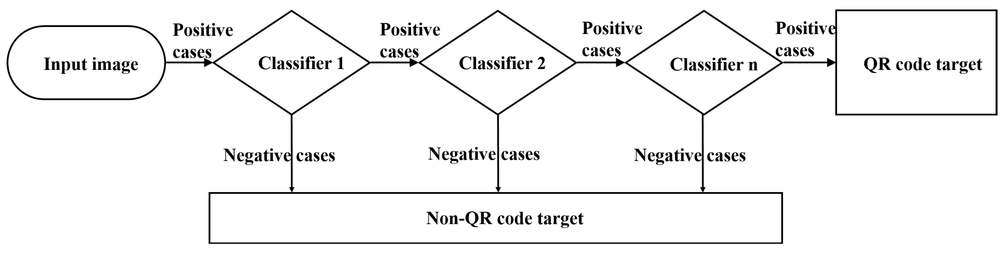
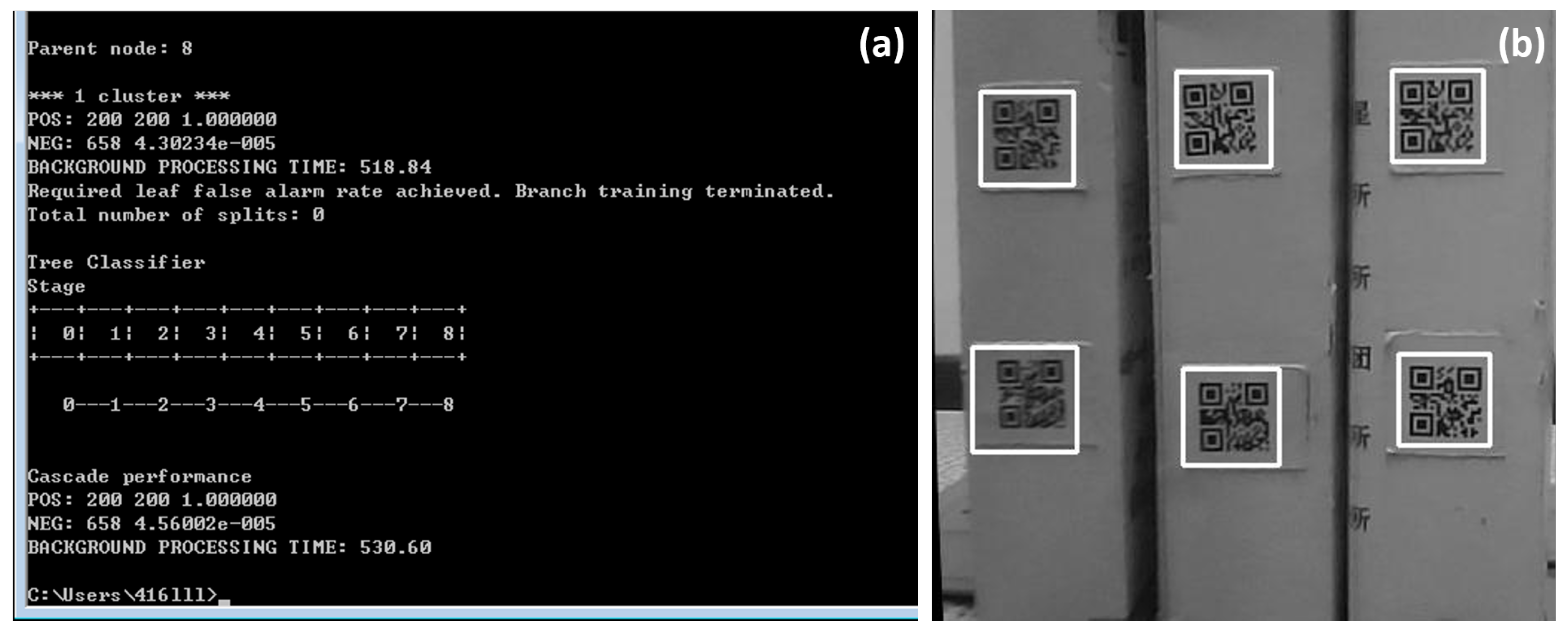
In this study, the stable self-adaptive Adaboost learning algorithm [
31] was adopted to improve the object detection accuracy. The Adaboost algorithm is based on a cascade classification model, as shown in
Figure 6, wherein a series of weak classifiers are cascaded together to improve the detection accuracy iteratively until the desired accuracy is achieved. The main purpose of such a strategy is to find an optimal weak classifier to achieve the lowest misclassification rate. Owing to the selective properties of those multi-level weak classifiers, the selection efficiency of the Adaboost learning algorithm was largely improved.
3.3. QR Code Based Positioning Accuracy Correction Algorithm
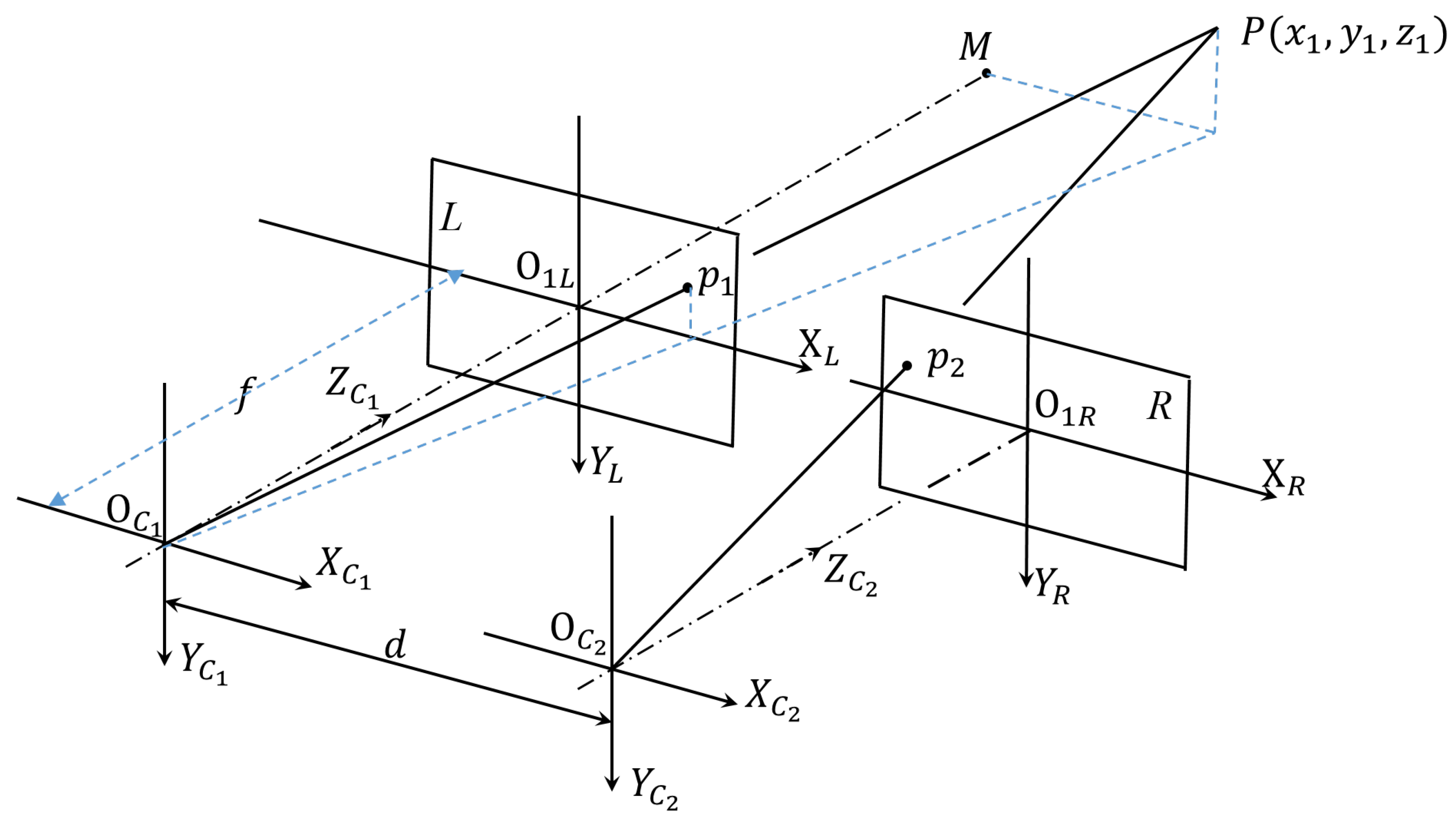
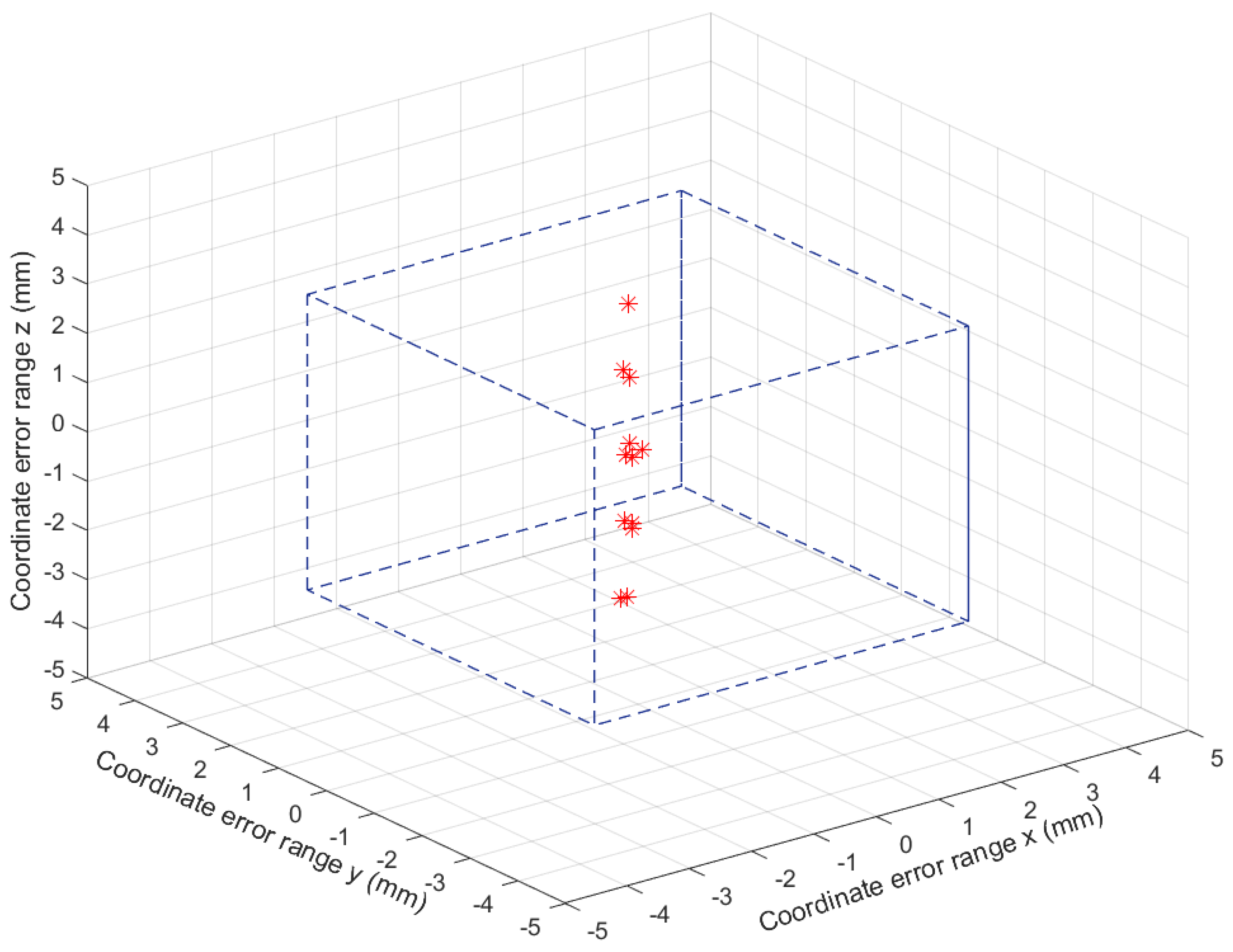
To improve the robot P&N accuracy, the robot operational errors accumulated in its navigation process must be eliminated. In this paper, a parallax processing-based 3D reconstruction algorithm was proposed, for such a purpose.
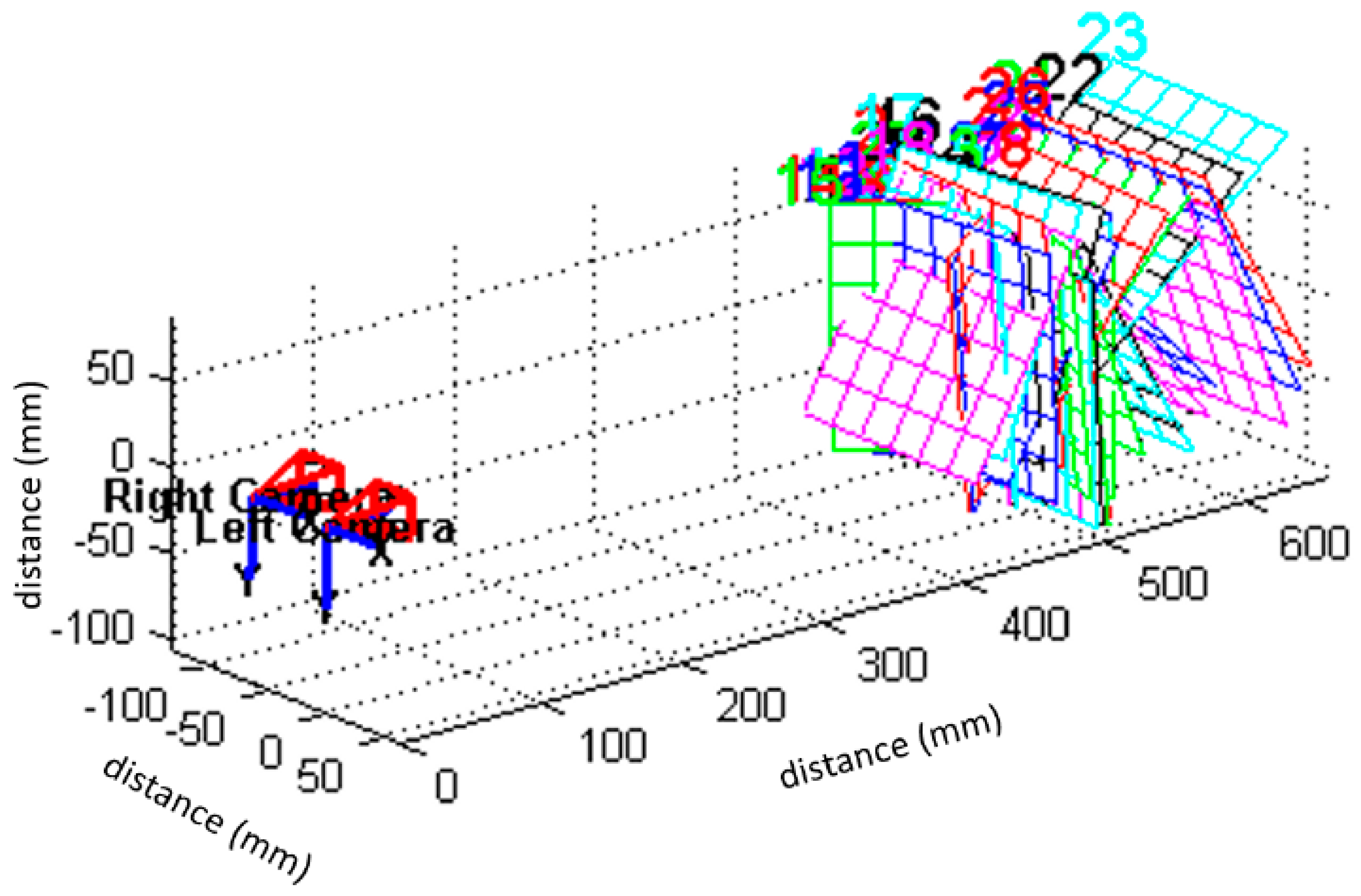
Figure 7 presents a schematic of the robot binocular vision system, wherein two identical cameras are utilized. Suppose that
and
are optical centers of the two cameras,
d is the distance between those two optical centers, and
f is the focal length of the camera. Further, assume that the coordinates of an object
P within the left and right camera coordinate systems, which are denoted to be
and
, are
and
, while its location in the two images acquired by the two cameras, is
and
, respectively. Hence, Equation (
11) can be obtained,
While the position of point
P within the 3D camera system could be obtained, as shown in Equation (
12),
where
, and
are intrinsic parameters of the cameras. They are the same as those in Equation (
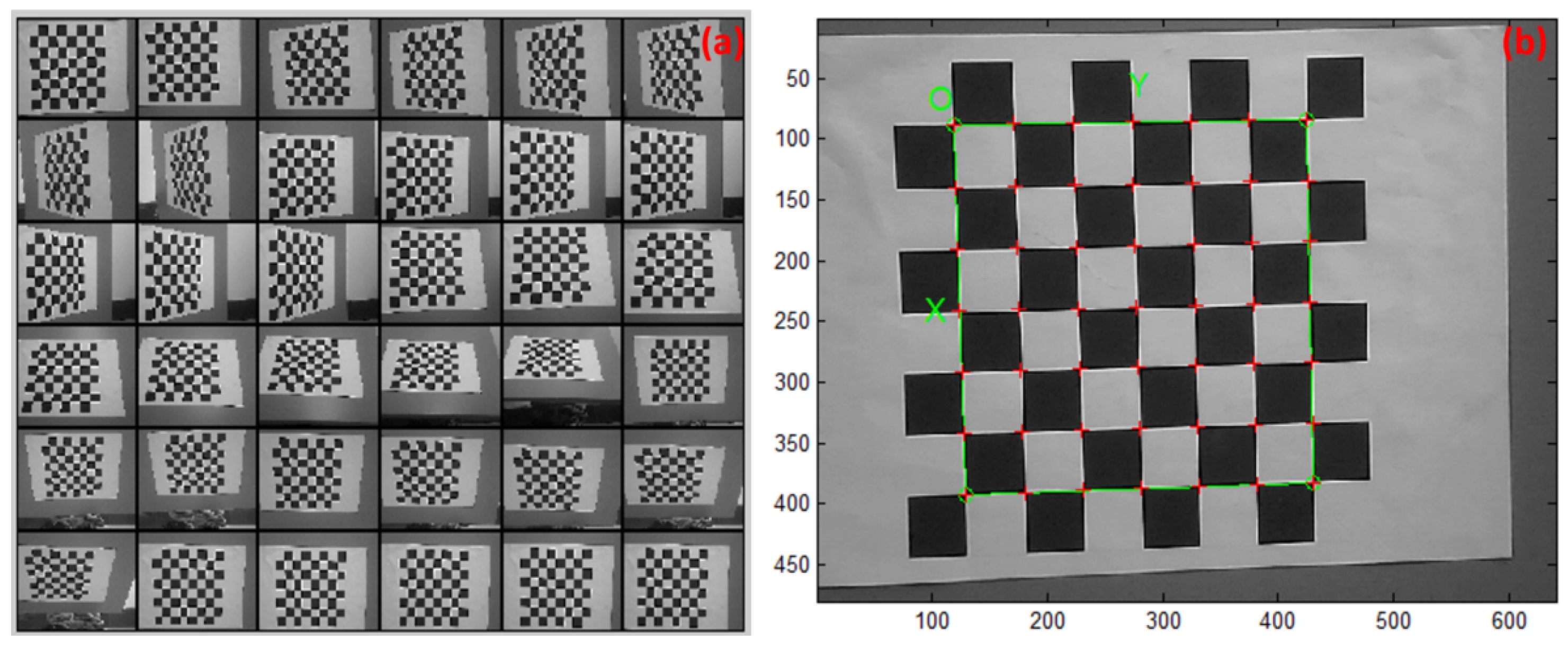
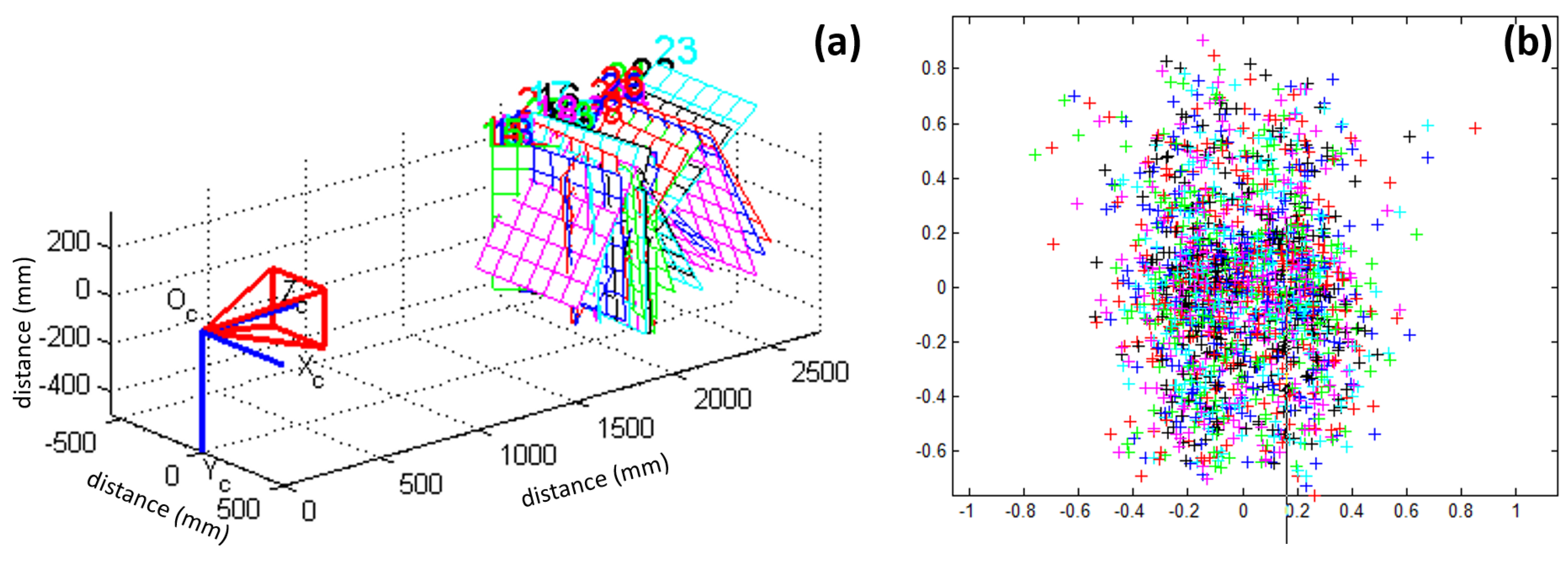
4), and are determined in the camera calibration process.
Therefore, once a number of QR code landmarks are identified, both the landmark position information within the 3D camera system and the relative position between the robot and the landmarks can be determined. Finally, the robot position within the free space coordinate system can also be obtained. In such a way, the robot positioning error accumulated within the robot navigation process could be eliminated. Meanwhile, both the robot gestures and its trajectory to the target could be adjusted.
3.4. Robot BAR Operation Algorithm
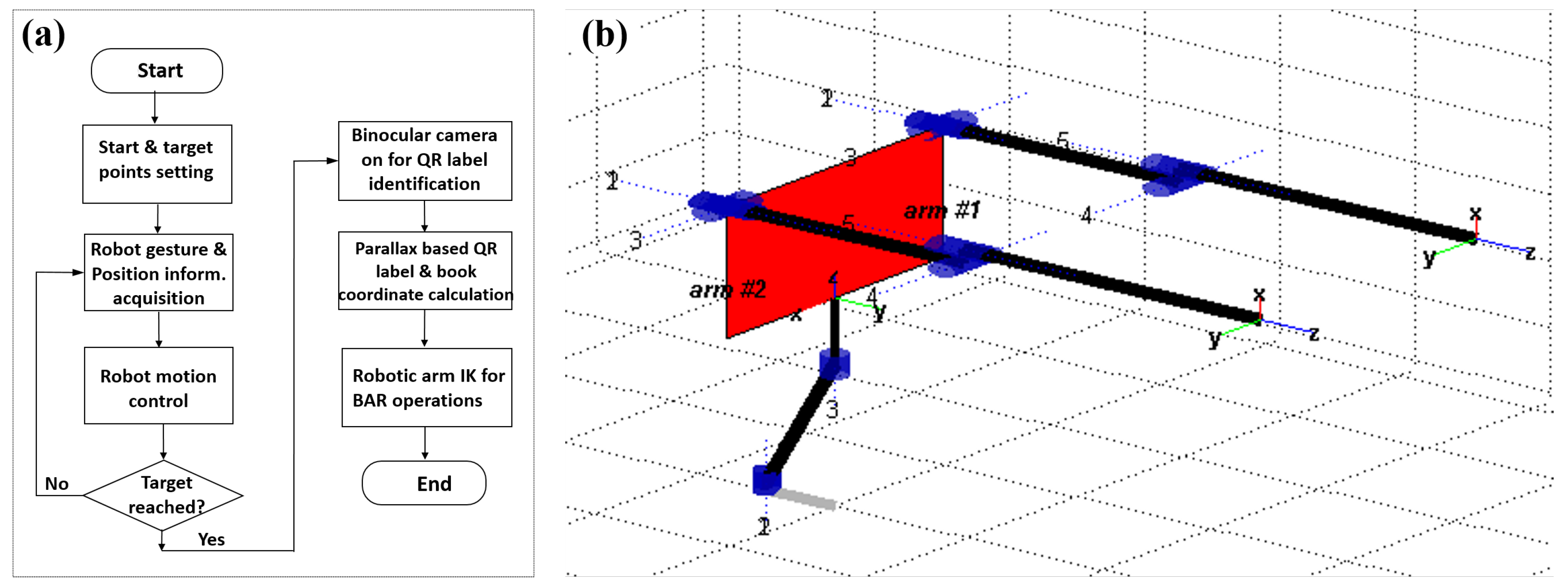
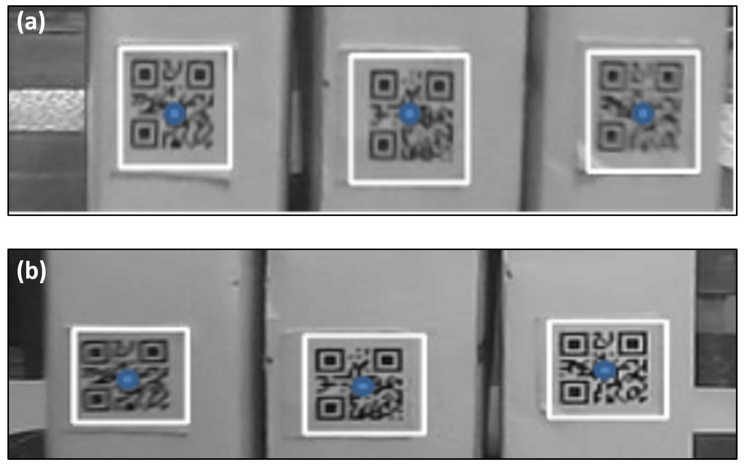
The robot BAR operations were implemented with its two robotic arms, and the binocular vision based robot BAR operation control mechanism is shown in
Figure 8a. Specifically, once the robot reaches the target along the calculated trajectory, its binocular cameras are turned on to search for the target QR code labels, and then the QR-code shape and feature point detection mechanism is utilized to extract the detailed book information (i.e., the position and orientation information within 3D free space coordinate system). Such acquired book coordinate information would finally drive the two robotic arms to work cooperatively to fulfill the BAR operations.
To fulfill such a BAR function, both the robotic kinematics [
32] and inverse kinematics [
33] of the library robot’s two robotic arms have to be determined. The robotic kinematics is used to calculate the final position of the robot accessing hand when given the operations of each joint structure, while the inverse kinematics (IK) is used to determine the operations of each robot joint structure once given the final position of the accessing hands. In this study, the robotic 4-DoFs manipulator, shown in
Figure 1b, was modeled as a serial joint link structure based upon the modified-DH convention [
34]. The link diagram for such a manipulator is illustrated in
Figure 8b, and its modified DH parameters are shown in
Table 1. Furthermore, since the relation between
-th and
i-th frame could be expressed by Equation (
13),
where
c and
s correspond to the
and
functions,
and
are link length and torsion angle along
a axis for frame
, respectively, and
and
are the link offset and rotation angle along
z axis for frame
, respectively. Then, the robotic kinematics of the two robotic arms could be expressed as shown in Equation (
14):
where the
matrix in the left upper corner describes the robot accessing hand gestures, while
denotes the accessing hand position within the spatial coordinate.
Further introducing Equation (
13) into Equation (
14), we have the parameters as follows,
where
.
In order to characterize the IK model for the library robot, those joint link parameters
to
have to be determined. By utilizing Equation (
15),
could be calculated with
and
(i.e.,
). Also, by using
and
,
could be obtained as
only when
(when
, the joint axis is at a singular point, and the IK model can not be solved). The parameter
could be obtained with
and
as
when
. By utilizing
and
, the parameter
could also be obtained with Equation (
16),
while the parameter
is determined as
.
Finally, the IK model for the two 4-DoFs robotic arms can described as below,
Therefore, once the final position of the accessing hand is determined (i.e., the center point of a bookmark label is accessed by the robot QR code label), such an IK model could be adopted to determine the operation gestures for those two robotic arms to fulfil the desired BAR operations. In this study, since the mechanical structure of those robotic arms are relatively simple, the algebraic method was adopted to obtain the IK model solutions.
While for the book returning process, the procedure of robot P&N is the exactly the same as that of the book accessing process. The only difference between the returning and accessing processes is to find the desired position on book shelf to put the book back. To do so, the robot would scan the book labels on the bookshelves first, and then search for the label IDs such that the ID of the book to be returned falls in between. In such a way, once the ID position is determined, both the robot motion displacement and its arm gestures could be determined. One of the robotic arm is controlled to take the book from the basket, while the other arm is driven to insert the accessing hand into two books that were found to obtain a space for the book. Finally, the book would be placed into this space to fulfill the returning operation.
5. Discussions and Conclusions
In this paper, we report an autonomous mobile robot to fulfill the high-precision BAR operations for modern libraries. The main contributions of this work are two-fold: First, we proposed for the first time (to the best of our knowledge), to integrate binocular vision and QR-code identification technologies together for autonomous mobile robots to improve both P&N and operational accuracies. Second, we designed and constructed a fully autonomous mobile robot for high-precision BAR operations and also verified the applicability of integration of this technology onto the constructed robot. Both simulations and experiments were conducted with the constructed robot to verify the effectiveness of such a technological combination in different cases. Results demonstrated that, with the binocular vision technology adopted for dynamic digital map constructions, autonomous P&Ns, obstacle identification and avoiding, and the QR code identification technique utilized for robot operational error eliminations and robotic arm BAR operation calculations, the robot P&N accuracies could be largely improved and the operation time significantly reduced.
It is worth noting that, within the processes of binocular camera system calibration as well as the object feature extraction and identifications, the binocular vision system imaging background is relatively simple and clean and, therefore, the influences of the environmental factors were omitted in this study. In practice, however, the binocular vision system imaging background could be complicated, and some other practical issues, such as people walking around, the QR-code occlusions, losing or misplacement issues, or too-weak illumination light intensities, would also largely impact on the robot’s performance. Such factors would impose a large burden on the combined binocular vision and QR-code identification mechanism, and sometimes may even cause the QR code label missing issue. Hence, both high-accuracy QR-FEI algorithms and efficient light intensity compensation mechanisms are highly desired to alleviate the influences of such environmental factors. Furthermore, since the main objective of this study was to evaluate the feasibility of the integrated binocular vision and QR-code identification technology for indoor mobile robot BAR operations, only sophisticated existing methods (e.g., the binocular vision based P&N, Haar feature-like extraction based QR-FEI algorithm, and -Lite algorithm) were deployed. In practice, however, alternative, more efficient methods could also be employed to enable the robot to work more efficiently. The effectiveness and efficiency of such a technological combination also demonstrated its great potential for various other applications. For example, it could be implemented in the companies and laboratories for robots to act as autonomous visitor guides or instructors, or in supermarkets, bookstores, and airports for robots to act as servants or load carriers. Currently, we are evaluating and verifying the applicability of such an integrated binocular vision and QR-code identification technology to an autonomous fruit harvesting robot.
It is also worth noting that, in this study, both the robot hardware fabrication and the software design were implemented according to our lab conditions. The overall cost of such a robot was less than USD, while the average time spent for each BAR operation conducted in the lab was measured to be 2.6 min. In practice, however, if such a robot was batch produced for practical applications, the robot cost could be further reduced, while the average BAR operation time could also be shortened. This is because the robot could be able to manipulate multiple books each time in practice. As compared to a human librarian (typically with a salary of USD per month), such a robot could not only help save the labour cost significantly, but also save the time required for BAR operations, especially when the number of books to be processed is large. Long working times and ease of maintenance are the other two advantages of the robot. Due to limited authority to access 3D coordinate information of any public libraries, however, the applicability of such a robot to any real libraries still has to be tested. Currently, we are applying for the permissions to verify the robot applicability within our university libraries.
Our future research work would cover two main aspects. First, sophisticated mechanisms for addressing those issues within real libraries, such as people walking around, the QR-code occlusions, loss or misplacement issues, and too-weak illumination light intensities, have to be developed to improve the robustness of the robot system. Second, more efficient identification and recognition algorithms are to be devised to further improve the P&N and BAR operation accuracies while reducing the system complexity and computational load. In addition, we are also extending the application areas of such an integrated binocular vision and QR code identification technology.

 ,
, 


