1. Introduction
In recent years, as humans recognized the importance of sustainable energy, increasing attention has been paid to piezoelectric materials for their applications such as in sensors, actuators, and energy-harvesting devices. The recent advances in piezoelectric composite materials for energy harvesting applications have been summarized [
1,
2]. Lead zirconate titanate (PZT) is a widely used piezoelectric ceramic material; a distinctive feature of PZT is its large piezoelectricity; however, poor mechanical properties limit its fields of application. The development of piezoelectric composites helps to overcome some of the limitations of conventional PZT ceramics by improving their demerits, especially brittleness, lack of reliability and conformability [
3,
4,
5].
Lead nickel niobite (PNN) and PZT particles dispersed in epoxy matrix (PNN–PZT/epoxy) have been fabricated as paint sensors on account of their low cost and weight [
6], and the impact sensitivity of the sensor according to different poling conditions has been measured in order to determine the optimal conditions of poling time and electric field. Experimental studies have revealed the effect of the poling conditions on the piezoelectricity of barium titanate (BTO) particles dispersed in an epoxy matrix (BTO/epoxy) [
7] and potassium sodium niobite (KNN) particles dispersed in an epoxy matrix (KNN/epoxy) [
8]. Piezoelectric glass fiber-reinforced polymer (GFRP) has also been manufactured using the mixture of PNN–PZT piezoelectric powder and epoxy as a smart resin, and it was shown that the piezoelectric GFRP could be utilized as an impact sensor [
9]. The polyvinylidene fluoride (PVDF) composite consisting of two PVDF films sandwiching a GFRP laminate has been proposed, and the energy-harvesting capability and open circuit voltage have been increased remarkably [
10]. Compared with conventional methods, a novel material-processing technique in which PZTs are covered by a thin patch of woven E-glass fiber fabric for enhanced adhesion with the surrounding epoxy matrix was designed, and the functionality of the proposed smart composite and its sensitivity in detecting material damage were examined [
11]. A macro fiber piezoelectric energy harvester has been integrated onto a carbon fiber-reinforced polymer (CFRP) composite laminate using the co-curing method [
12], whereas piezoelectric CFRP composite laminate has been developed by embedding a lead-free piezoelectric nanoparticle-filled epoxy interlayer with GFRPs [
13]. KNN nanoparticle-filled epoxy/CFRP composite generators have been fabricated and polarized successfully, proving that polarization was obtainable even when CFRP was used as the electrodes of KNN nanoparticle-filled epoxy resin [
14].
On the other hand, an impact detection system based on a metal core piezoelectric fiber/aluminum (Al) composite has been developed [
15]. Impact load position was estimated and the minimum required accuracy for a structural health monitoring (SHM) system was satisfied. When the piezoelectric ceramic fiber/Al matrix composite was subjected to temperature changes during its manufacturing process, differences between the coefficients of thermal expansion (CTEs) of the fiber and matrix cause large thermal stresses to be induced within the fiber. The residual thermal stresses may change the characteristics of piezoelectric composite materials. It is therefore important to accurately evaluate the magnitudes of the residual thermal stresses in the piezoelectric composites during manufacturing and their piezoelectric response during service. For PZT ceramics, it has been reported that the materials lose their piezoelectric properties near the Curie temperature; however, their domain configurations remain unchanged [
16]. Algueró et al. [
17] investigated the electromechanical properties of PZT ceramics by heating. The experimental results of repolarized ceramics showed that a high level of poling is retained. On the other hand, Lee et al. [
18] studied the effect of the residual stress induced during the heat-treatment process on the properties of PZT films. They showed that the remnant and saturation polarizations increase when a compressive stress is induced. Although the effect of temperature on the piezoelectric behavior of PZT ceramics has been investigated, systematic and fundamental studies on the thermally induced electromechanical behavior of the piezoelectric composite materials are limited [
19,
20] and more work is needed.
The finite element method (FEM) is regarded as an important tool for solving problems of engineering and mathematical methods. Some finite element works on the modeling and design of the piezoelectric composite materials have been presented [
21,
22,
23]. By using the FEM, we can easily obtain the electromechanical response for piezoelectric composite materials.
In this paper, we investigated the electromechanical response of metal-core piezoelectric fiber-reinforced Al matrix (metal-core piezoelectric fiber/Al) composite material subjected to thermal and mechanical loading. Three-dimensional finite element simulations of the metal-core piezoelectric fiber/Al matrix composite material were conducted, and the residual thermal stress generated during the solidification process of the Al matrix was predicted. The piezoelectricity of this composite was characterized by FEM, and then the output voltage of the composite under concentrated load was calculated in consideration of its use as a load position detection sensor. In addition, the numerical and measured values of the residual stress were compared.
2. Analytical Procedure
2.1. Basic Equations
Considering a piezoelectric material with no body force and free charge. The field Equations in the Cartesian coordinates
xi (
i = 1, 2, 3) were given by
where
σij and
Di are the components of the stress tensor and electric displacement vector, respectively, a comma followed by an index denotes partial differentiation with respect to the space coordinates
xi, and the Einstein summation convention over repeated indices was used. The relation between the strain tensor component
εij and the displacement vector component
ui is given by
and the electric field intensity vector component
Ei is:
where
ϕ is the electric potential. Constitutive relations can be written as
where
T is the temperature,
,
,
are the elastic compliance, piezoelectric coefficient, and dielectric permittivity at constant stress, respectively, and
is the CTE, which satisfy the following symmetry relations:
In Equation (6),
pi is the pyroelectric constant. The constitutive Equations (5) and (6) for piezoelectric material poled in the
x3 direction are:
where:
2.2. Model
The finite element analysis software, ANSYS
®, was used in this investigation. A three-dimensional finite element model was necessary to accurately present the electromechanical field distribution of the metal-core piezoelectric fiber/Al matrix composite material.
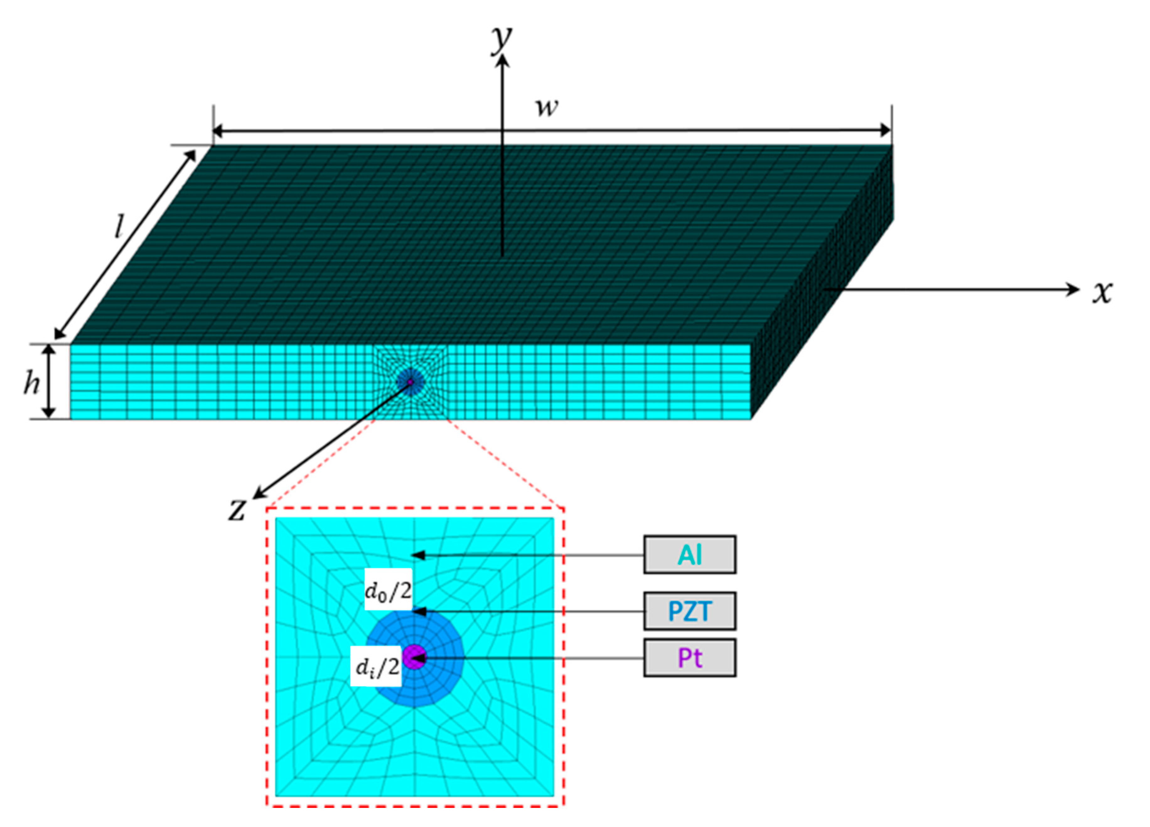
Figure 1 shows the finite element model. A rectangular Cartesian coordinate system (
x,
y,
z) is used for modeling with coincidence between the
z axis and the direction of the piezoelectric fiber. Meanwhile, the origin of the coordinate system coincides with the center of the composite material. This model consists of a platinum (Pt) fiber (diameter
di, length
l) embedded into a circular PZT tube (outer diameter
do, inner diameter
di and length
l) and an Al plate (length
l, width
w, and thickness
h). The problem was also formulated using a cylindrical coordinate system (
r,
θ,
z), where the longitudinal axis of the Pt core also coincides with the
z axis. We assumed that the Curie temperature of the PZT fiber was 127 °C. Hence, the direction of each electric domain in PZT was randomly oriented [
24], and the piezoelectric coefficients were zero above the Curie temperature.
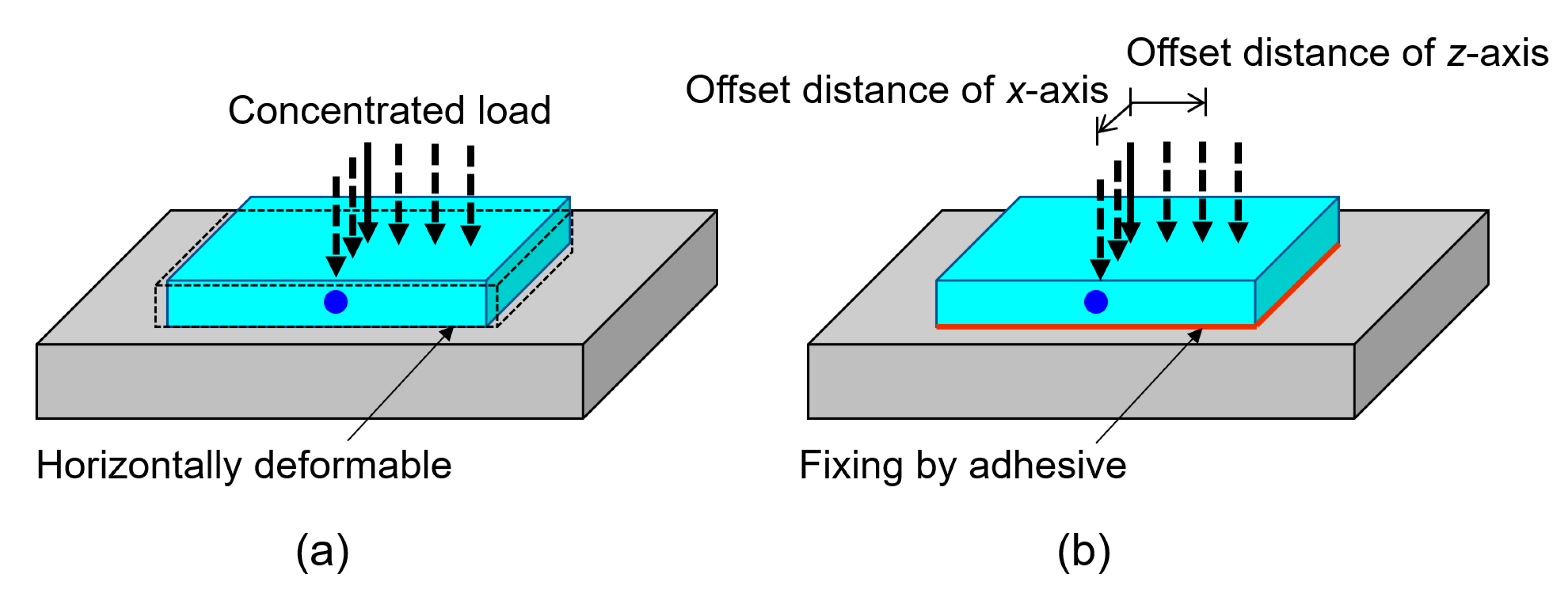
We considered the following thermal and mechanical loadings of the piezoelectric fiber/Al matrix composite material: (i) the composite was cooled from high temperature
T = 660 °C (melting point of pure Al), 600 °C or 400 °C to 20 °C (room temperature) and (ii) after cooling, we considered the mechanical loading, i.e., the composite was under tensile stress
σzz =
σ0 at
z =
l/2 and the displacement
uz = 0 at
z = −
l/2. In addition, in order to examine the performance of the load position detection sensor of this metal-core piezoelectric fiber/Al matrix composite material, we applied the concentrated load of 1 N at various locations on the top surface (
y =
h/2). At this time, it was assumed that the bottom surface had two types, that is, the case where the center point is fixed (
ux =
uy =
uz = 0 at
x = 0,
y = −
h/2,
z = 0) and the case where the whole surface is fixed (
ux =
uy =
uz = 0 at −
w/2
x w/2,
y = −
h/2, −
l/2
z l/2). Here, the model with the center point fixed assumes the composite material placed on a rigid floor (this support is horizontally deformable as shown in
Figure 2a), and the model with the whole surface fixed shows the composite material bonded to a rigid floor (
Figure 2b).
Table 1 lists the material properties of PZT used for each domain that is randomly distributed. For simplicity, the pyroelectric constant was ignored here.
Table 2 lists the Young’s modulus
E, Poisson’s ratio
ν and the CTE of Al and Pt. The length, width, and thickness of the composite are
l = 20 mm,
w = 5 mm, and
h = 0.55 mm. The outer diameter and inner diameter of the PZT tube are
do = 0.2 mm and
di = 0.05 mm, respectively.
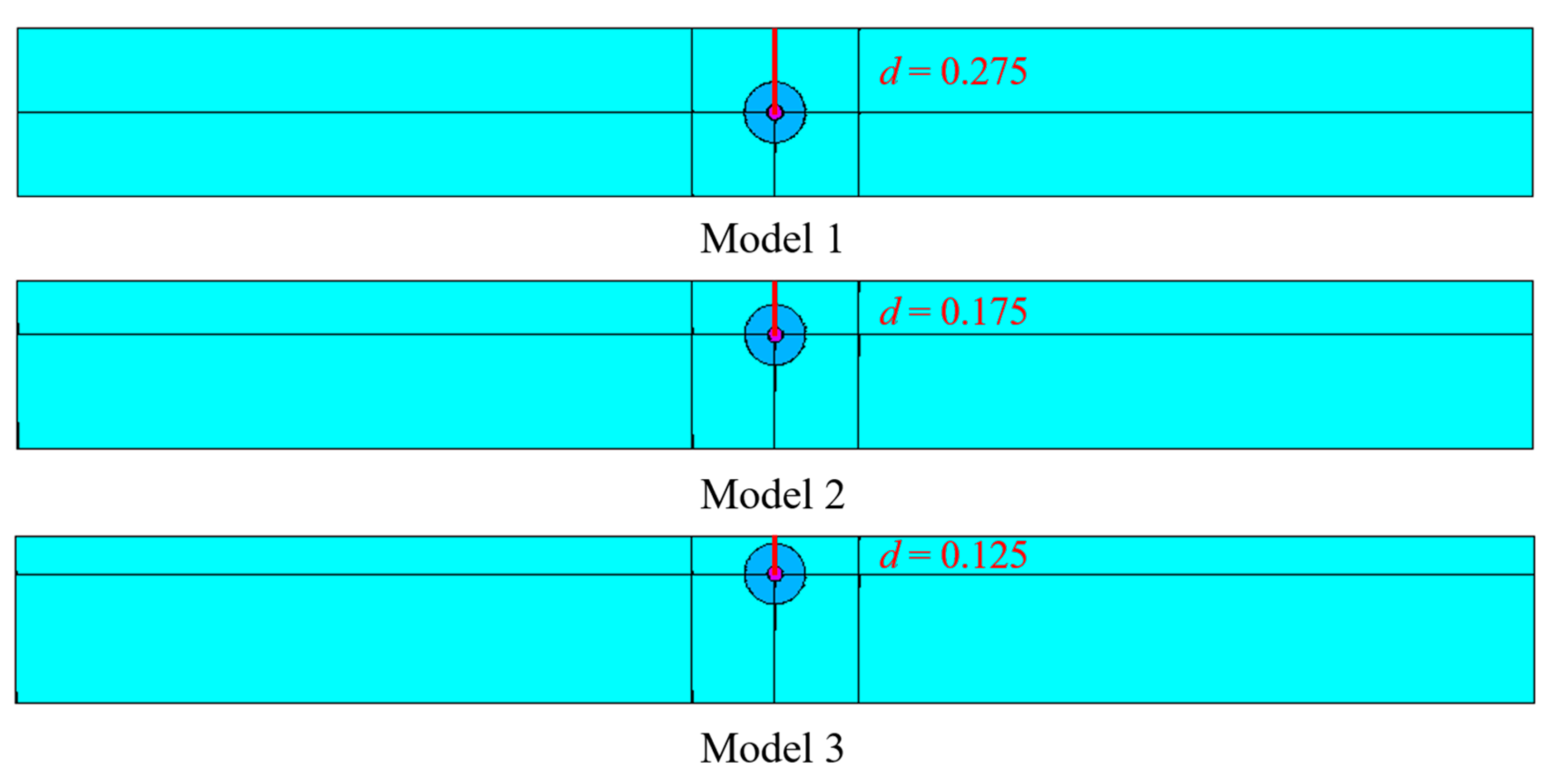
In addition, the distance
d from the center of the Pt to one side of the
y axis was changed to locate the optimal position of the PZT fiber as shown in
Figure 3. The distances from the plate surface to the fiber center for Models 1, 2 and 3 were
d = 0.275, 0.175 and 0.125 mm, respectively.
3. Experimental Procedure
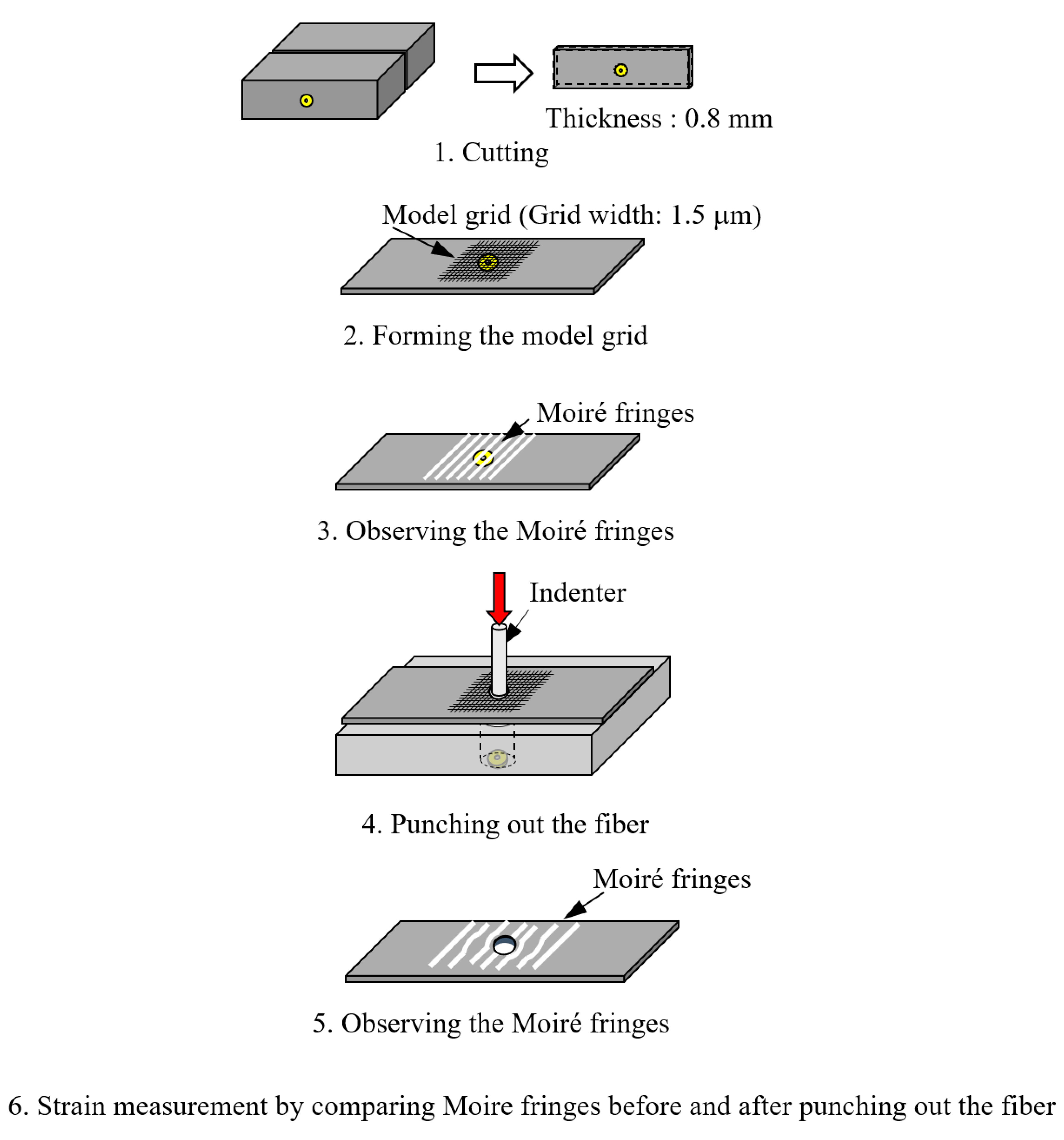
Details of the preparation of the sample can be found in Ref. 15. Metal-core piezoelectric fiber, Al plate with a U-shaped groove on which a copper (Cu) foil is placed on the surface, and the Al plate were prepared. After placing the metal-core piezoelectric fiber into the groove, another Al plate was placed over the fiber and Cu foil, and hot pressing was performed at 600 °C. After hot pressing, the composite sample was cut off.
The compressive residual stress generated in the metal-core piezoelectric fiber/aluminum composite was measured by the electron beam Moiré method [
25]. Using this method, the microscopic deformation of Al when the metal core piezoelectric fiber was removed was measured, and the residual stress was determined from the deformation (
Figure 4).
A metal-core piezoelectric fiber/Al composite was cut with a diamond cutter (IsoMet Low Speed, Buehler Corp. Lake Bluff, IL, USA) to prepare a 0.8 mm-thick specimen. An electron beam resist (ZEP520A, Zeon Co., Ltd. Tokyo, Japan) was uniformly applied to the polished specimen surface with a spin coater (1H-D7, Misaka Inc. Tokyo, Japan), and it was dried at 50 °C for 3.6 ks using a drying oven (FO-30WT, Tokyo Garasu Kikai Co., Ltd. Tokyo, Japan). The coated resistance was exposed in a grid pattern by scanning an electron beam with a scanning electron microscope (SEM, SX-40A, Topcon Corp. Tokyo, Japan) at intervals of 1.5 μm, and the resistance in the portion irradiated with the electron beam was removed by a developer (ZED-N50, Zeon Co., Ltd. Tokyo, Japan). A model grid was formed by depositing gold onto the removed portion using a sputtering device (JFC-1500, JEOL Ltd. Tokyo, Japan). After this, the Moiré fringes generated using an irradiating electron beam as a master grid for this model grid were observed by SEM.
Subsequently, the specimen was fixed to a jig and the piezoelectric fiber was punched out of the Al with an indenter with a diameter of 0.15 mm. After this, the Moiré fringes were observed by the same method as described above. The residual stress was calculated from the strain that was measured by comparing the Moiré fringes before and after punching out the fiber.
4. Results and Discussion
4.1. Analytical Results
To simulate the Al solidification process, the reference temperature was defined as the melting point of Al (660 °C) for thermal stress calculations.
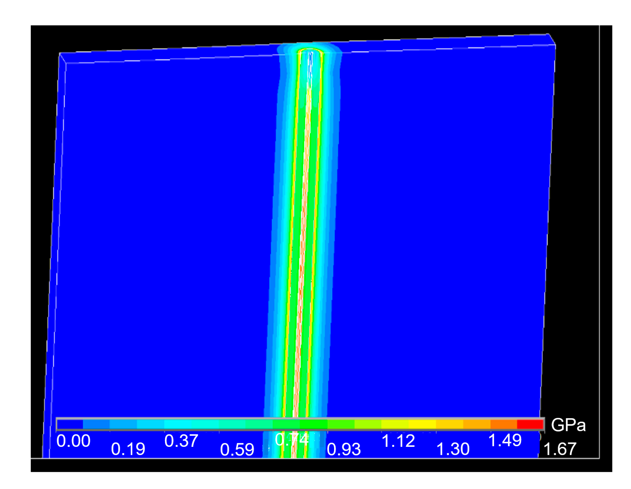
Figure 5 shows the distribution of the thermal stress of the piezoelectric fiber/Al matrix composite after the Al solidified. High compressive residual stress can be observed at the interface between the PZT fiber and the Al matrix. After the piezoelectric composite was manufactured, electrical poling was necessary for achieving piezoelectricity.
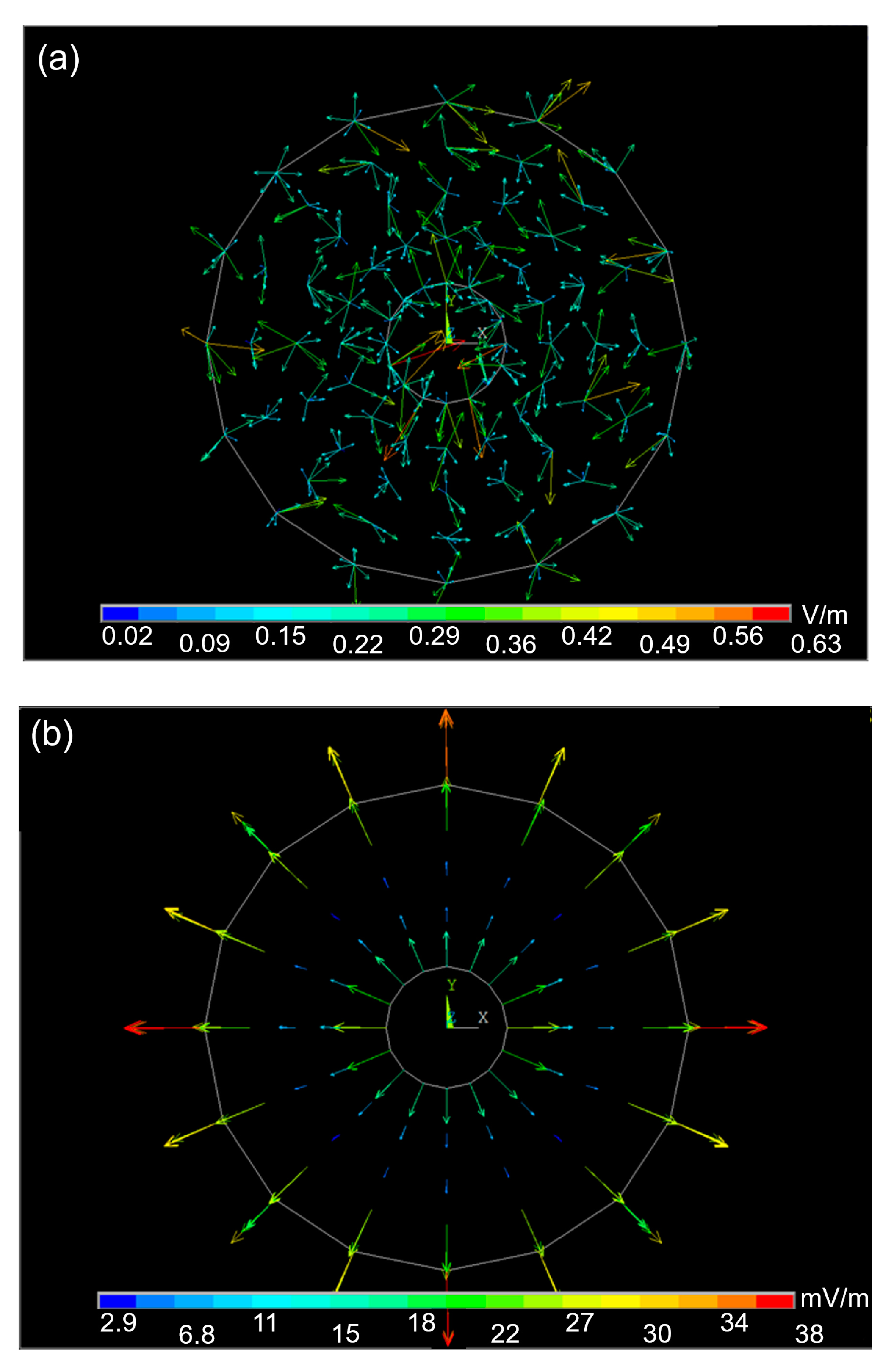
Figure 6a shows the initial direction of the electric field of the PZT fiber.
Figure 6b demonstrates the change in the direction of the electric field, after the temperature decreases from the melting point to room temperature. This indicates that when the temperature decreased from high temperature to room temperature, a large residual stress was generated, and as a result, an electric field was generated and polarized. In the polarization process, the Pt was used as the electrode, hence the direction of polarization was radial.
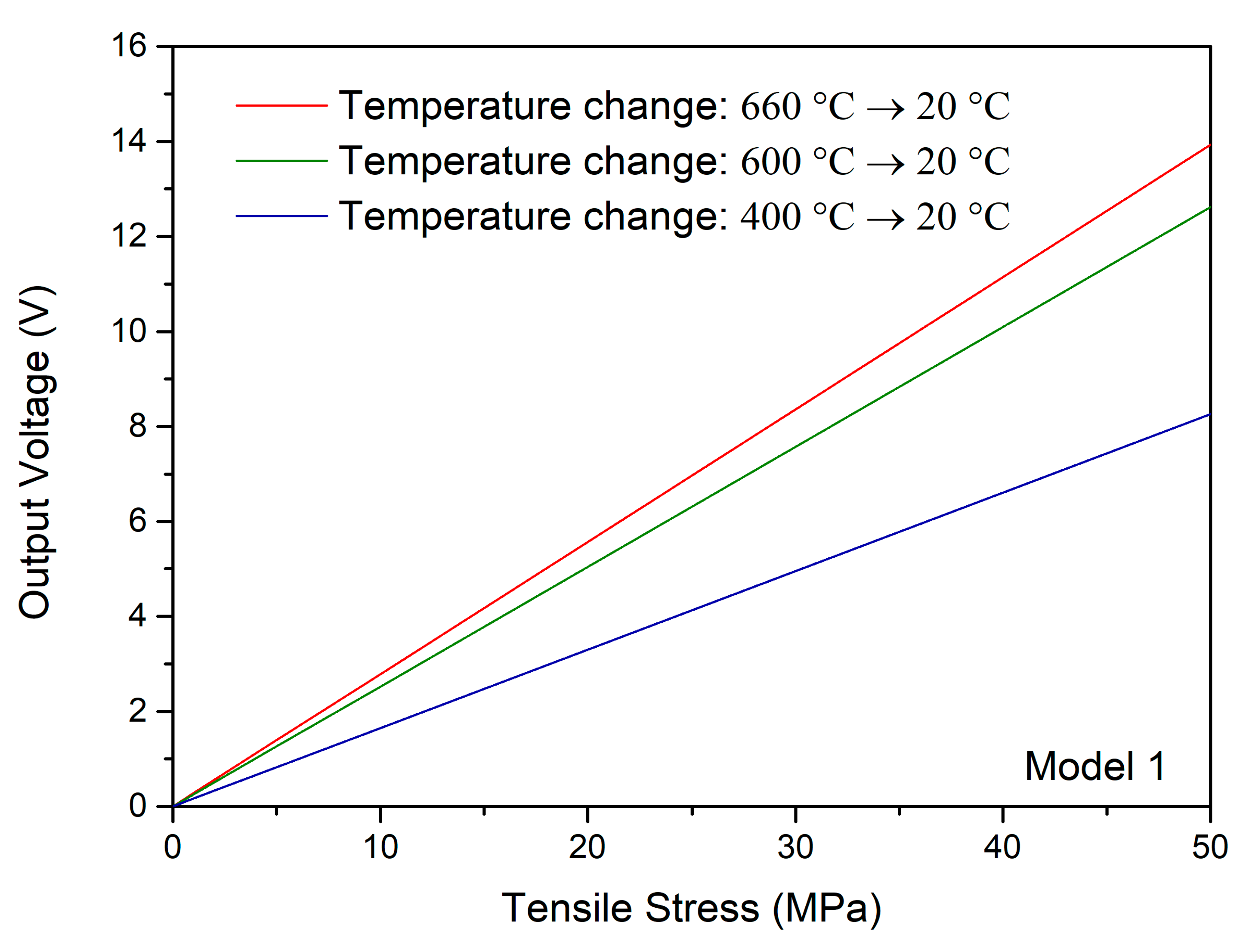
Then, the piezoelectricity was characterized by applying tensile stress to calculate the output voltage response. Under the residual stress and applied tensile stress
σ0 = 1 MPa, the output voltage
Vout = 1.11 V was obtained. We also examined the piezoelectric properties of the piezoelectric fiber/Al matrix composite under the residual stress in detail. The output voltage was recorded when different residual stresses were considered, and all boundary conditions were set as the same.
Figure 7 indicates the output voltage of different residual stress situations versus applied tensile stress. We can clearly see that output voltages are increased according to the additions of tensile stresses, and the relationship between output voltage and applied tensile stress is linear. Nevertheless, when residual stress is added, the output voltage is larger, and the increment of output voltage is also larger. This is because when this composite was subjected to tensile stress, the strain was increased owing to the high compressive residual stress, so that the piezoelectricity of this composite can be improved. This situation may be applicable to the other piezoelectric composites with a different fiber size, shape, and matrix material. The results for the evaluation of output voltage and residual stress may help piezoelectric composite designers to optimize performance.
Instead of the usual use as an energy-harvesting device (e.g., piezoelectric vibration energy harvester [
26,
27]), we tried to utilize this composite as a load position detection sensor, and its performance was discussed. We assumed that this composite was used for this application by fixing the central point of the bottom surface (
Figure 2a) or settling all points of the bottom surface (
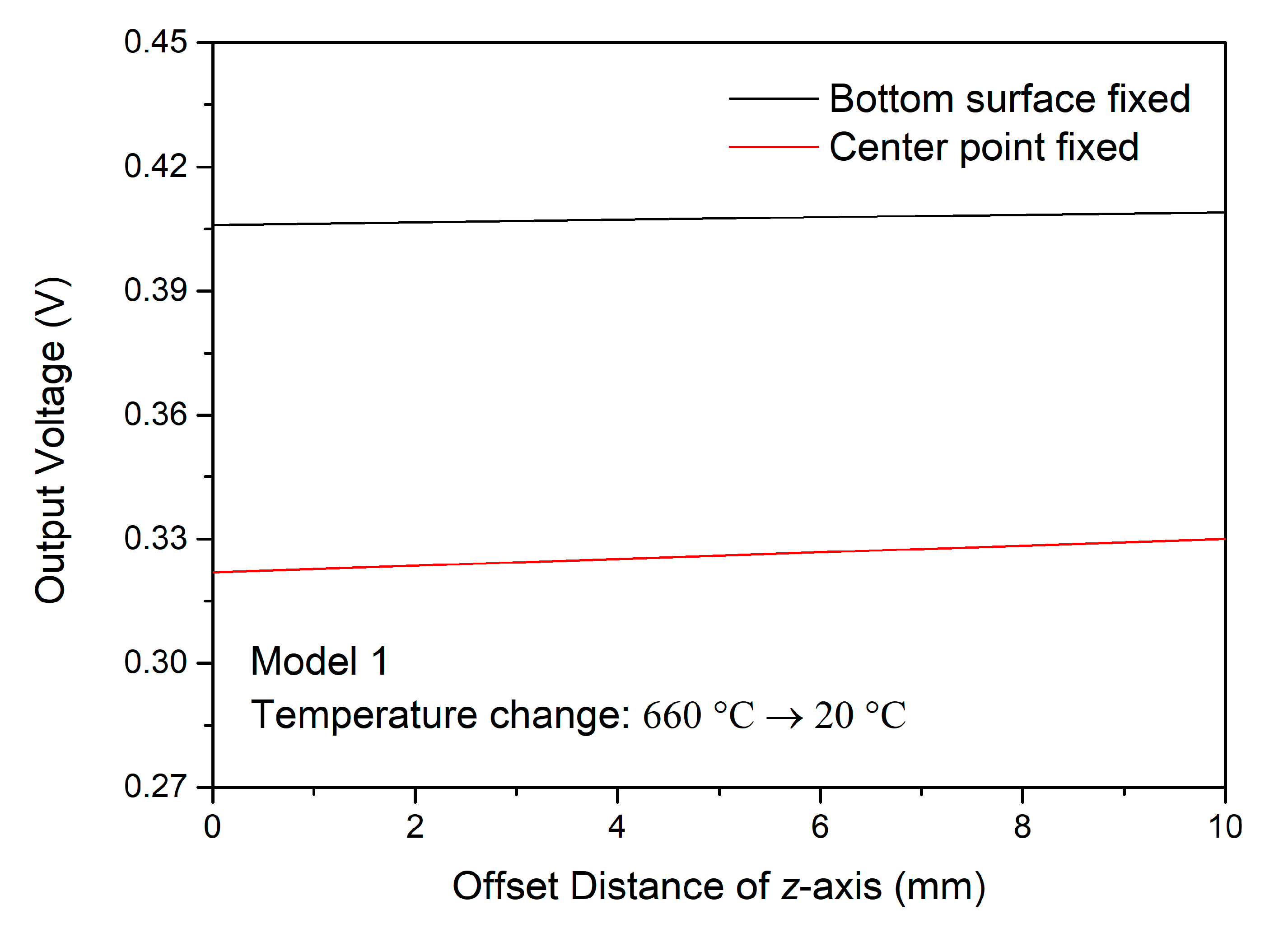
Figure 2b) as an embedded sensor. Through checking the output voltage under the same magnitude of concentrated load but different applied position, the relationship between output voltage and offset distance can be clarified. As a result of the symmetry, the center of the top surface was set as the initial point. The results of the output voltage and offset distance along the
z axis and
x axis were shown in
Figure 8 and
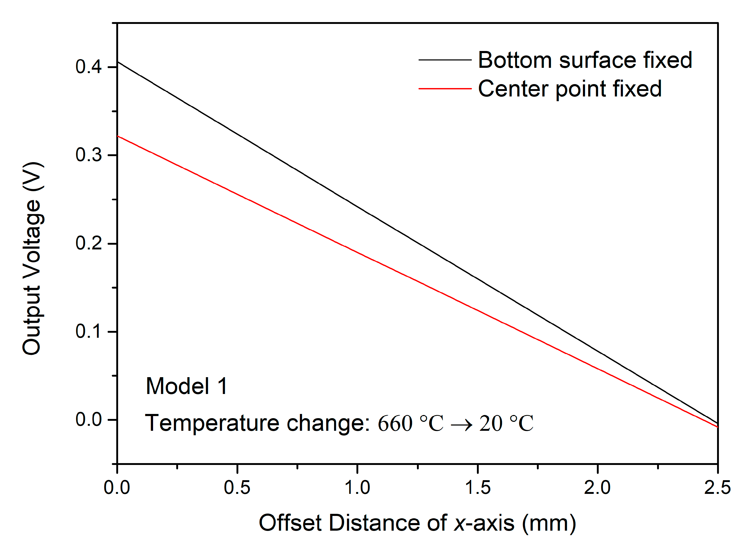
Figure 9, respectively. For the
z axis, the output voltage variation changing the
z coordinate value of the force point (point at which the force is applied) was very small. Nevertheless, the output voltage change along the
x axis is conspicuous, and as the offset distance along the
x axis increases, the output voltage decreases. From these results, we can predict the offset distance along the
x axis based on the output voltage. When detecting the offset distance along the
z axis, it is necessary to arrange the two PZT fibers in a cross shape. It was also shown that when used as the load position detection sensor, the performance is better if all points of the bottom surface of the composite are fixed.
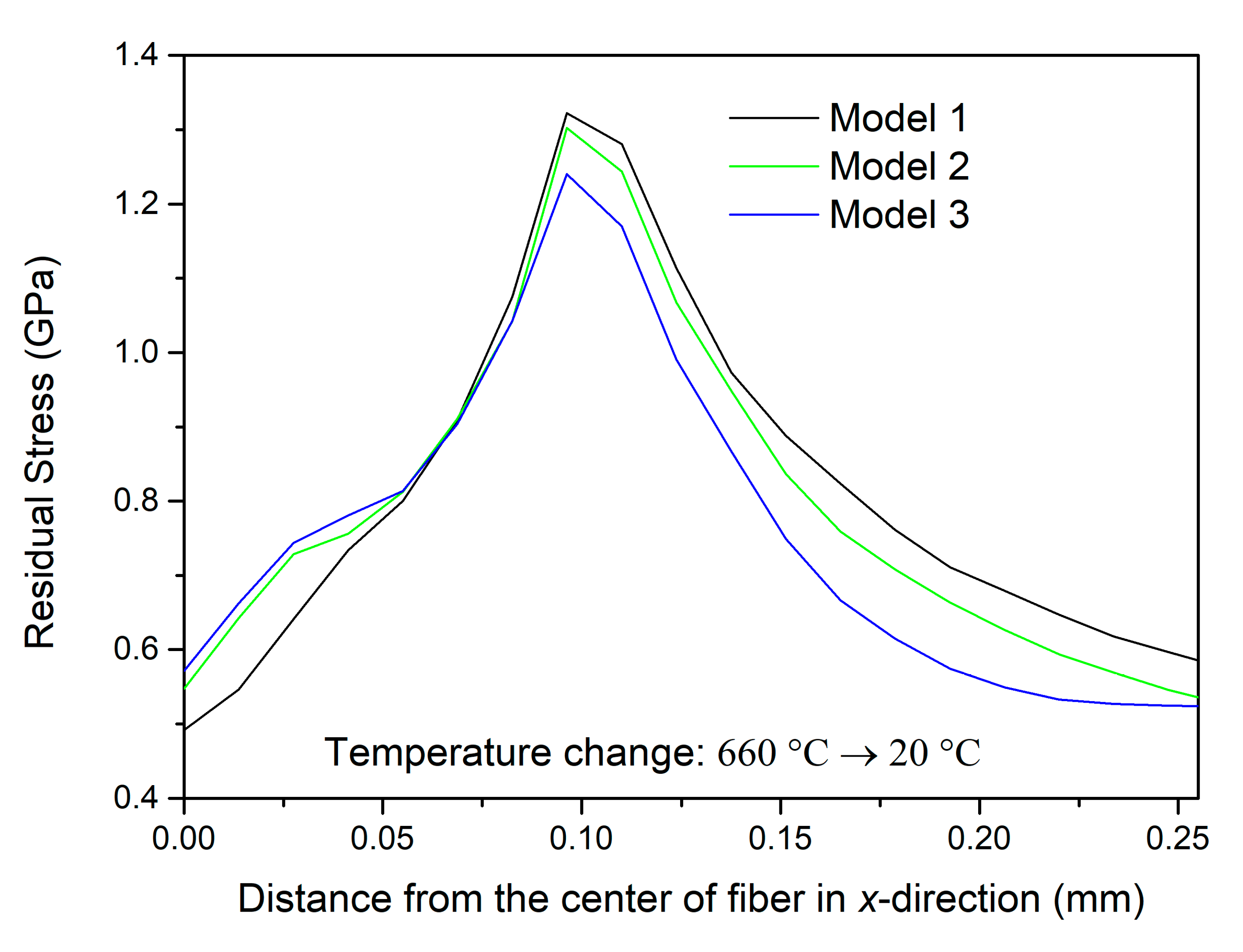
Furthermore, the relationship between the compressive residual stress
σxx and distance
d for the three models are also shown in
Figure 10. The residual stresses of the three models all reached the peak value in the interface of the PZT fiber and Al matrix first, then decreased. Simultaneously, the residual stresses of Model 1 were larger than the other two models due to the symmetry. The higher the compressive residual stress, the better the piezoelectricity of the composite (see
Figure 7). Therefore, it is desirable to embed the PZT fiber in the center of the Al plate as much as possible.
4.2. Experimental Results
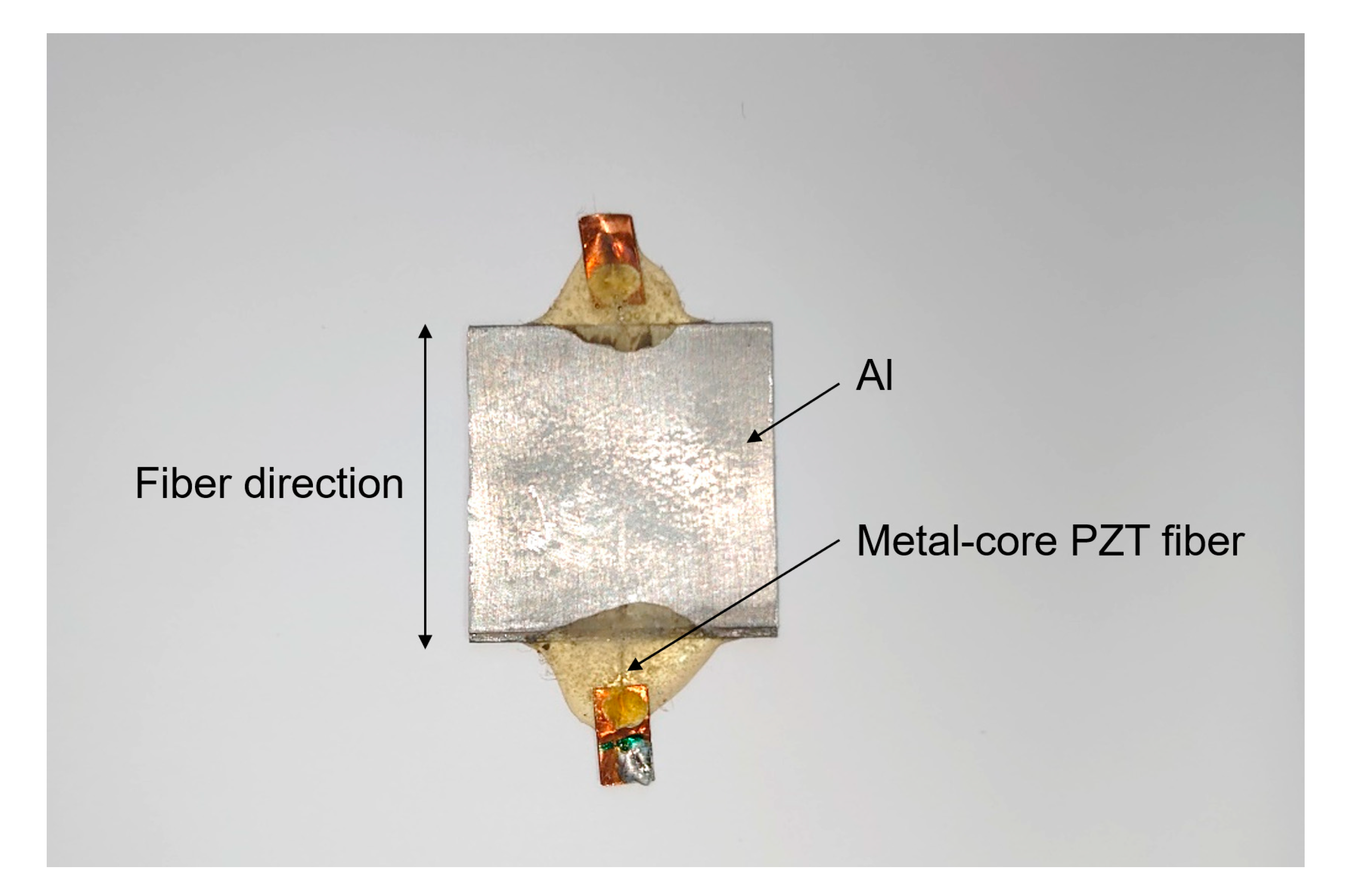
Figure 11 shows a metal-core piezoelectric fiber/Al composite sample.
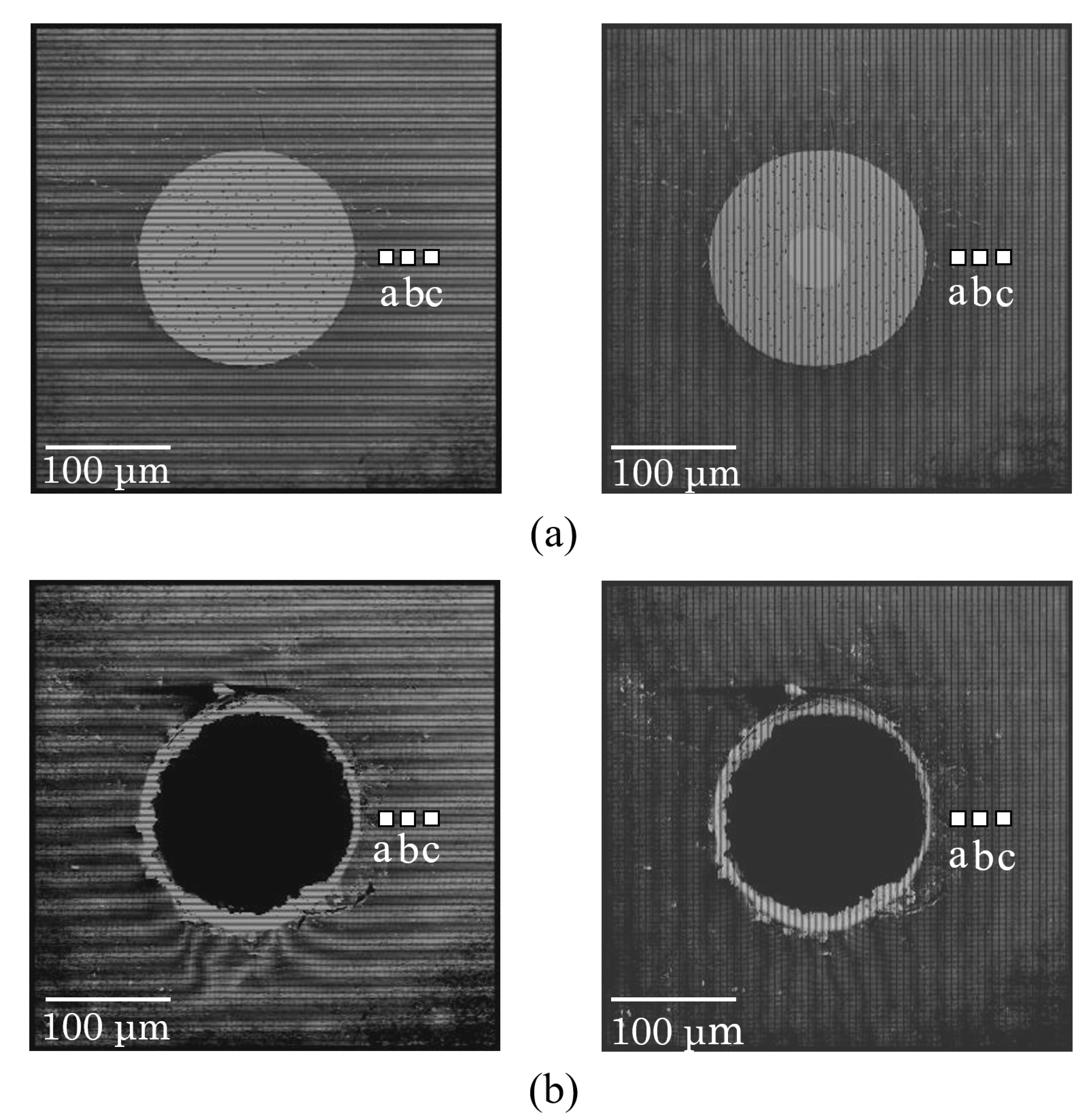
Figure 12 shows the SEM images the Moiré patterns (a) before and (b) after metal-core piezoelectric fiber indentation. The right side of the photos is the Moiré pattern in the
x direction, and the left is the one in the
y direction. The obtained strains in the
x and
y directions are converted into the stress in the radial direction.
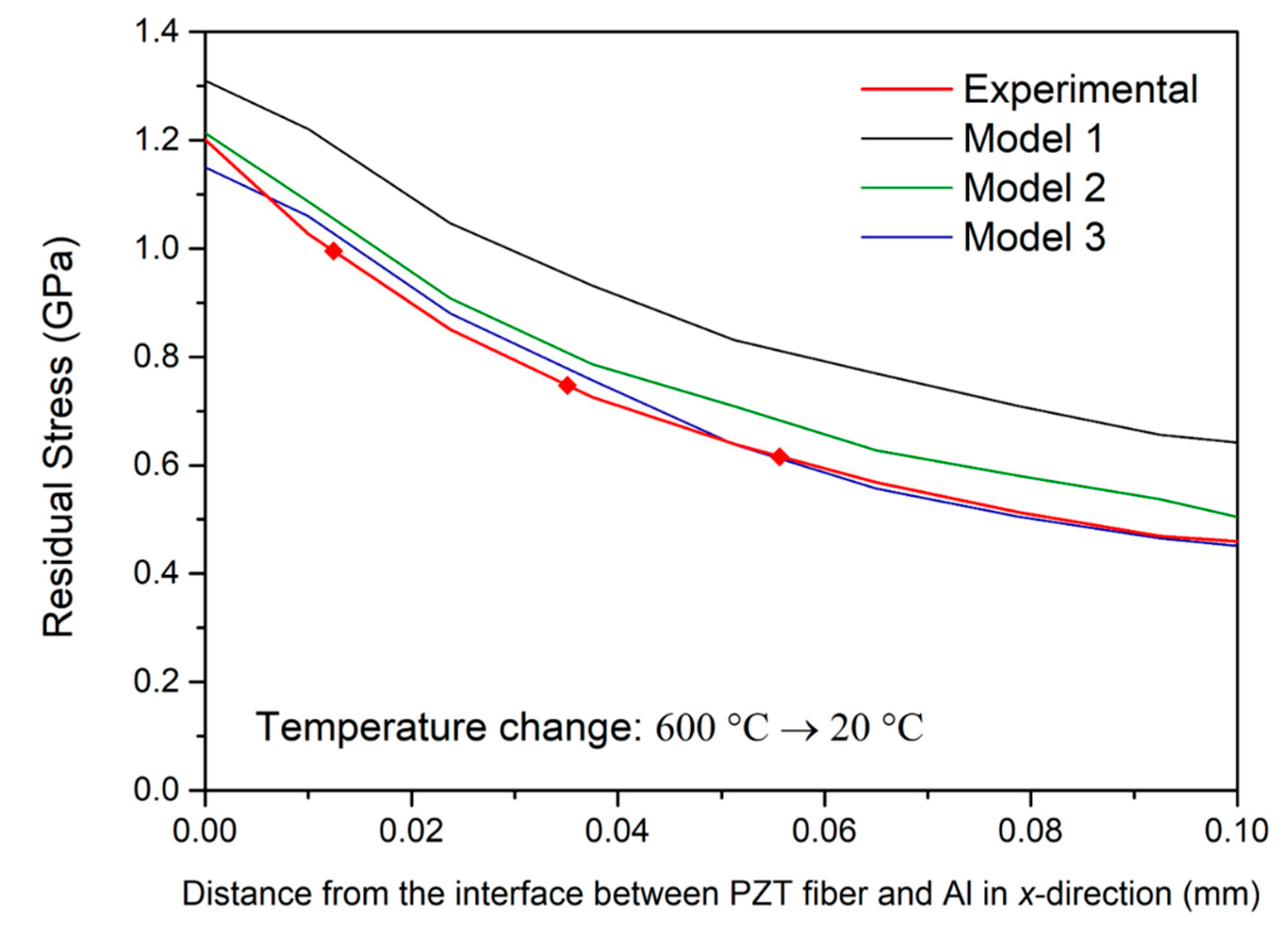
Figure 13 shows the measured values (red dot) of the compressive residual stress and its approximate curve (red line) for the metal-core piezoelectric fiber/Al composite sample. The calculated values of the three models after the temperature decreased from 600 °C to 20 °C are also shown. The experimental value falls between Model 2 and Model 3; considering that the experimental error may occur during the manufacturing process, it can be inferred that the theoretical value agrees with the experimental value.
5. Conclusions
Numerical and experimental approaches were presented to characterize the electromechanical response of metal-core piezoelectric fiber/Al composite subjected to thermal and mechanical loading. It was found that the residual stress dramatically increases the piezoelectricity of the metal-core piezoelectric fiber/Al composites. It was also shown that this composite is useful as a load position sensor. The results of this study will help to offer a basis for optimizing piezoelectric composite performance by selecting the optimal residual stress and structure.
Author Contributions
Conceptualization, T.Y., H.S. and H.A.; methodology, Y.W.; software, Y.W.; validation, H.K.; formal analysis, Y.W.; investigation, Y.W. and T.Y.; writing—original draft preparation, Y.W. and T.Y.; writing—review and editing, H.K. and F.N.; visualization, Y.W.; supervision, F.N.; project administration, H.A.; funding acquisition, H.A. and F.N. All authors have read and agreed to the published version of the manuscript.
Funding
This research was funded by JSPS KAKENHI Grant Number 17H03141 and 19H00733.
Conflicts of Interest
The authors declare no conflict of interest.
References
- Narita, F.; Fox, M. A Review on Piezoelectric, Magnetostrictive, and Magnetoelectric Materials and Device Technologies for Energy Harvesting Applications. Adv. Eng. Mater. 2018, 20, 1700743. [Google Scholar] [CrossRef] [Green Version]
- Mishra, S.; Unnikrishnan, L.; Nayak, S.K.; Mohanty, S. Advances in Piezoelectric Polymer Composites for Energy Harvesting Applications: A Systematic Review. Macromol. Mater. Eng. 2019, 304, 1800463. [Google Scholar] [CrossRef] [Green Version]
- Hasegawa, R.; Mehnert, M.; Mergheim, J.; Steinmann, P.; Kakimoto, K. Behavior of Vibration Energy Harvesters Composed of Polymer Fibers and Piezoelectric Ceramic Particles. Sens. Actuators A 2020, 303, 111699. [Google Scholar] [CrossRef]
- Chamankar, N.; Khajavi, R.; Yousefi, A.A.; Rashidi, A.; Golestanifard, F. A Flexible Piezoelectric Pressure Sensor Based on PVDF Nanocomposite Fibers Doped with PZT Particles for Energy Harvesting Applications. Ceram. Int. 2020, 46, 19669–19681. [Google Scholar] [CrossRef]
- Quinsaat, J.E.Q.; Wild, T.; Nüesch, F.A.; Damjanovic, D.; Krämer, R.; Schürch, G.; Häfliger, D.; Clemens, F.; Sebastian, T.; Dascalu, M.; et al. Stretchable Piezoelectric Elastic Composites for Sensors and Energy Generators. Compos. Part B Eng. 2020, 198, 108211. [Google Scholar] [CrossRef]
- Han, D.-H.; Kang, L.-H. Piezoelectric Characteristics of PNN-PZT/Epoxy Paint Sensor According to the Poling Conditions. Sens. Actuat. A Phys. 2018, 269, 419–426. [Google Scholar] [CrossRef]
- Wang, Z.; Narita, F. Corona Poling Conditions for Barium Titanate/Epoxy Composites and Their Unsteady Wind Energy Harvesting Potential. Adv. Eng. Mater. 2019, 21, 1900169. [Google Scholar] [CrossRef]
- Wang, Z.; Narita, F. Fabrication of Potassium Sodium Niobate Nano-Particle/Polymer Composites with Piezoelectric Stability and Their Application to Unsteady Wind Energy Harvesters. J. Appl. Phys. 2019, 126, 224501. [Google Scholar] [CrossRef]
- Hwang, M.Y.; Kang, L.-H. Characteristics and Fabrication of Piezoelectric GFRP Using Smart Resin Prepreg for Detecting Impact Signals. Compos. Sci. Technol. 2018, 167, 224–233. [Google Scholar] [CrossRef]
- Wu, G.; Li, A.; Wu, L.; Hu, N.; Yao, J.; Zhang, J.; Yuan, W.; Ning, H.; Liu, Y.; Atobe, S.; et al. Enhancement of Energy Harvesting Capability Using PVDF/GFRP-Laminated Films. J. Sandw. Struct. Mater. 2019, 21, 2548–2562. [Google Scholar] [CrossRef]
- Andreades, C.; Mahmoodi, P.; Ciampa, F. Characterisation of Smart CFRP Composites with Embedded PZT Transducers for Nonlinear Ultrasonic Applications. Compos. Struct. 2018, 206, 456–466. [Google Scholar] [CrossRef]
- Alsaadi, A.; Shi, Y.; Pan, L.; Tao, J.; Jia, Y. Vibration Energy Harvesting of Multifunctional Carbon Fibre Composite Laminate Structures. Compos. Sci. Technol. 2019, 178, 1–10. [Google Scholar] [CrossRef]
- Narita, F.; Nagaoka, H.; Wang, Z. Fabrication and Impact Output Voltage Characteristics of Carbon Fiber Reinforced Polymer Composites with Lead-Free Piezoelectric Nano-Particles. Mater. Lett. 2019, 236, 487–490. [Google Scholar] [CrossRef]
- Wang, Z.; Kurita, H.; Nagaoka, H.; Narita, F. Potassium Sodium Niobate Lead-Free Piezoelectric Nanocomposite Generators Based on Carbon-Fiber-Reinforced Polymer Electrodes for Energy-Harvesting Structures. Compos. Sci. Technol. 2020, 199, 108331. [Google Scholar] [CrossRef]
- Yanaseko, T.; Sato, H.; Narita, F.; Kuboki, I.; Asanuma, H. Improvement Estimation Accuracy of Impact Detection Using Metal-Core Piezoelectric Fiber/Aluminum Composites. Adv. Eng. Mater. 2019, 21, 1900550. [Google Scholar] [CrossRef]
- Law, H.H.; Rossiter, P.L.; Simon, G.P.; Unsworth, J. A Model for the Structural Hysteresis in Poling and Thermal Depoling of PZT Ceramics. J. Mater. Sci. 1995, 30, 4901–4905. [Google Scholar] [CrossRef]
- Algueró, M.; Guiu, F.; Reece, M.J. Degradation of PZT-4D Hard Piezoceramics under Moderate Heating. J. Eur. Ceram. Soc. 2000, 20, 2705–2711. [Google Scholar] [CrossRef]
- Lee, J.-W.; Park, C.-S.; Kim, M.; Kim, H.-E. Effects of Residual Stress on the Electrical Properties of PZT Films. J. Am. Ceram. Soc. 2007, 90, 1077–1080. [Google Scholar] [CrossRef]
- Yoon, K.J.; Park, K.H.; Parka, H.C.; Perreux, D. Thermal Deformation Analysis of Curved Actuator LIPCA with a Piezoelectric Ceramic Layer and Fiber Composite Layers. Compos. Sci. Tech. 2003, 63, 501–506. [Google Scholar] [CrossRef]
- Yoon, K.J.; Park, K.H.; Lee, S.K.; Goo, N.S.; Park, H.C. Analytical Design Model for a Piezo-Composite Unimorph Actuator and Its Verification using Lightweight Piezo-Composite Curved Actuators. Smart Mater. Struct. 2004, 13, 459–467. [Google Scholar] [CrossRef]
- Narita, F.; Fox, M.; Mori, K.; Takeuchi, H.; Kobayashi, T.; Omote, K. Potential of Energy Harvesting in Barium Titanate Based Laminates from Room Temperature to Cryogenic/High Temperatures: Measurements and Linking Phase Field and Finite Element Simulations. Smart Mater. Struct. 2017, 26, 115027. [Google Scholar] [CrossRef]
- Jia, Y.; Wei, X.; Xu, L.; Wang, C.; Lian, P.; Xue, S.; Al-Saadi, A.; Shi, Y. Multiphysics Vibration FE Model of Piezoelectric Macro Fibre Composite on Carbon Fibre Composite Structures. Compos. Part B 2019, 161, 376–385. [Google Scholar] [CrossRef] [Green Version]
- Liu, Y.; Du, S.; Micallef, C.; Jia, Y.; Shi, Y.; Hughes, D.J. Optimisation and Management of Energy Generated by a Multifunctional MFC-Integrated Composite Chassis for Rail Vehicles. Energies 2020, 13, 2720. [Google Scholar] [CrossRef]
- Shindo, Y.; Narita, F.; Hirama, M. Electromechanical Field Concentrations near the Electrode Tip in Partially Poled Mutilayer Piezo-Film Atuators. Smart Mater. Struct. 2009, 18, 085020. [Google Scholar] [CrossRef]
- Dally, J.W.; Read, D.T. Electron-Beam Moire. Exp. Mech. 1993, 33, 270–277. [Google Scholar] [CrossRef]
- Shindo, Y.; Narita, F. Dynamic Bending/Torsion and Output Power of S-Shaped Piezoelectric Energy Harvesters. Int. J. Mech. Mater. Des. 2014, 10, 305–311. [Google Scholar] [CrossRef]
- Hara, Y.; Yamamoto, Y.; Makihara, K. Self-Sensing State Estimation of Switchcontrolled Energy Harvesters. J. Intell. Mater. Sys. Struct. 2020, 31, 2326–2341. [Google Scholar] [CrossRef]
© 2020 by the authors. Licensee MDPI, Basel, Switzerland. This article is an open access article distributed under the terms and conditions of the Creative Commons Attribution (CC BY) license (http://creativecommons.org/licenses/by/4.0/).


 ,
, 


