Development of a Solar-Powered IoT-Based Instrument for Automatic Measurement of Water Clarity


Abstract
:1. Introduction
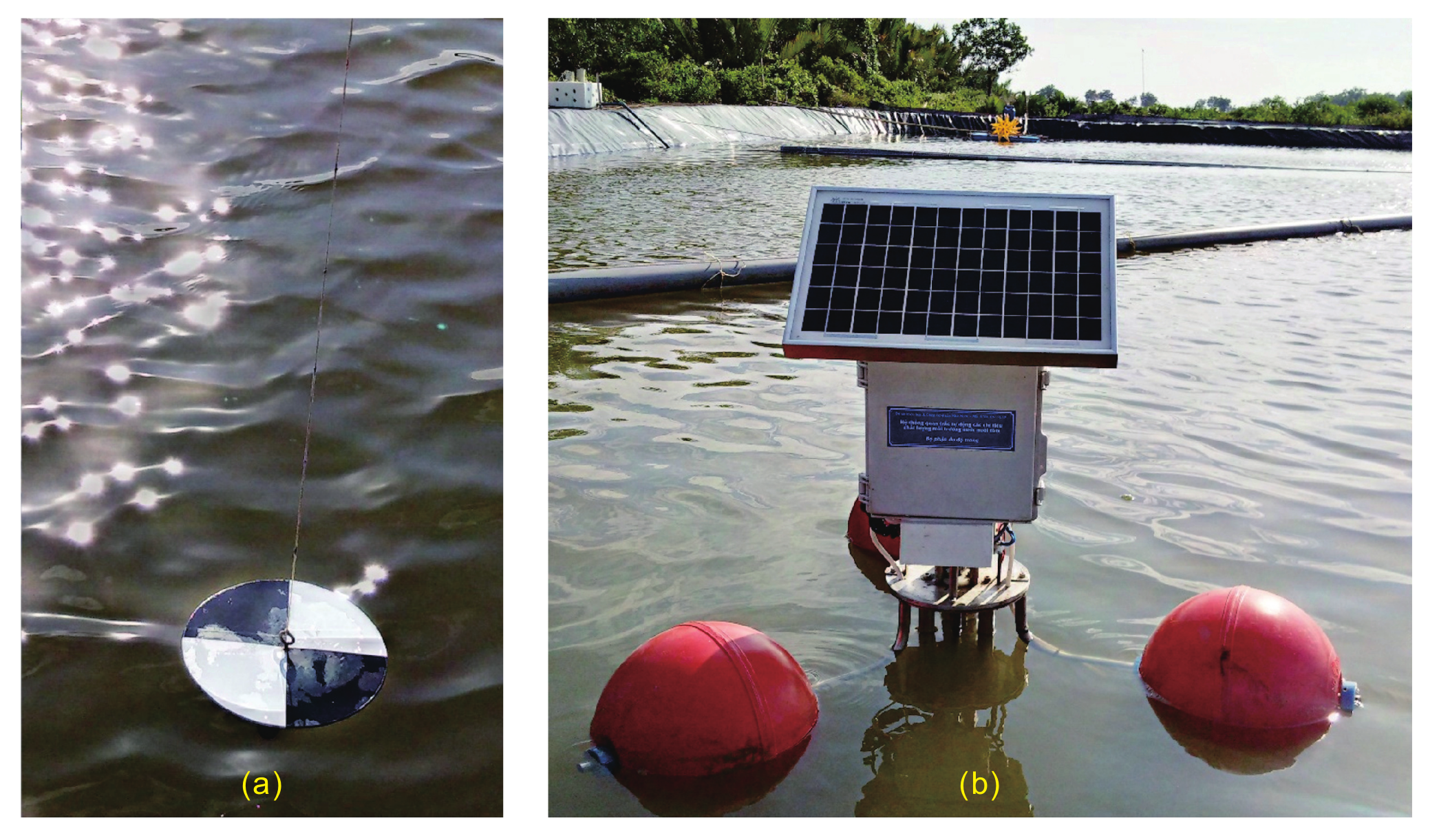
2. Introduction to Our Proposed Instrument
2.1. Main Features
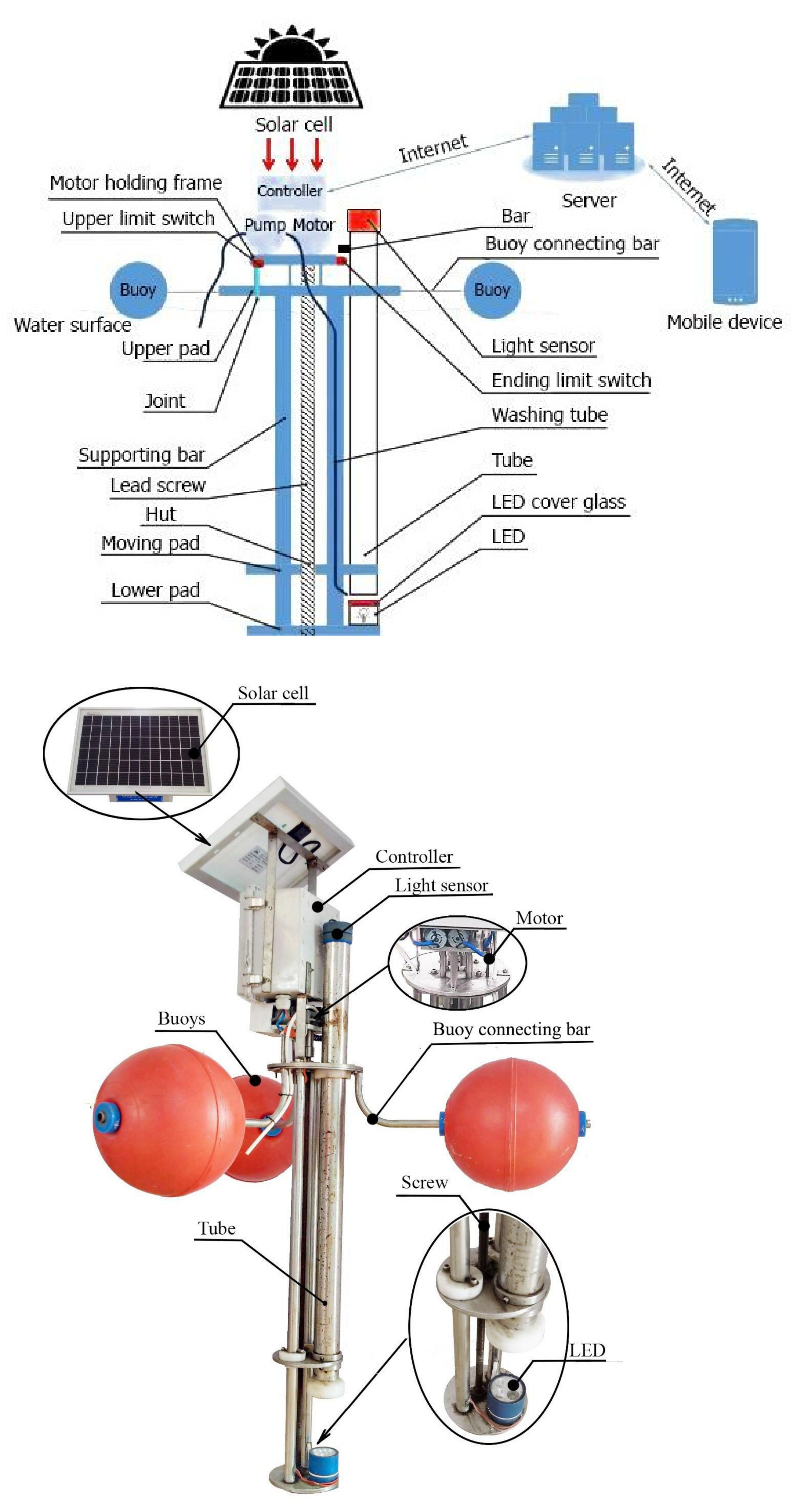
2.2. Structure
2.2.1. Frame and Buoy Assembly
2.2.2. Measuring Assembly
2.2.3. Power Assembly
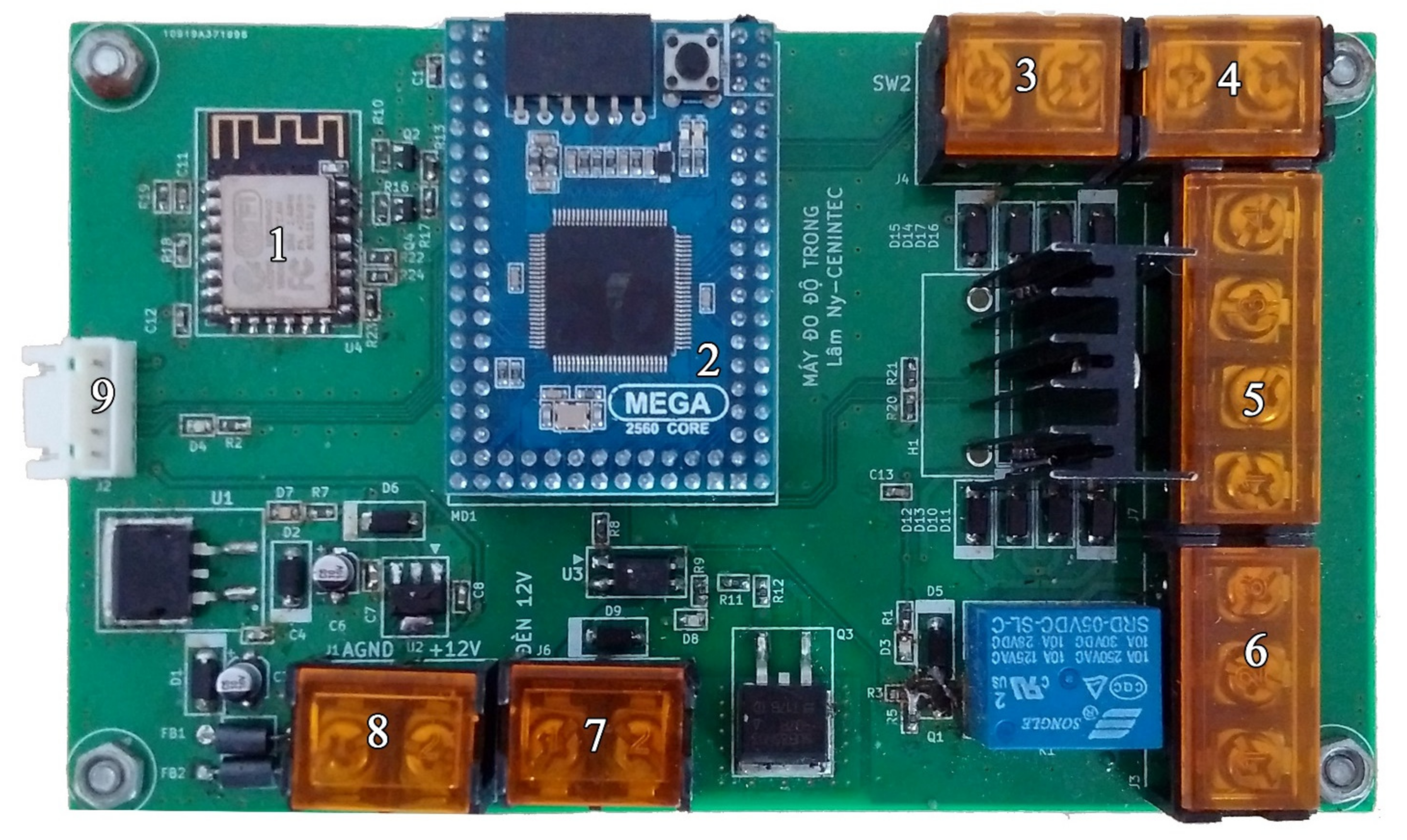
2.2.4. Control Assembly
2.3. Working Principle
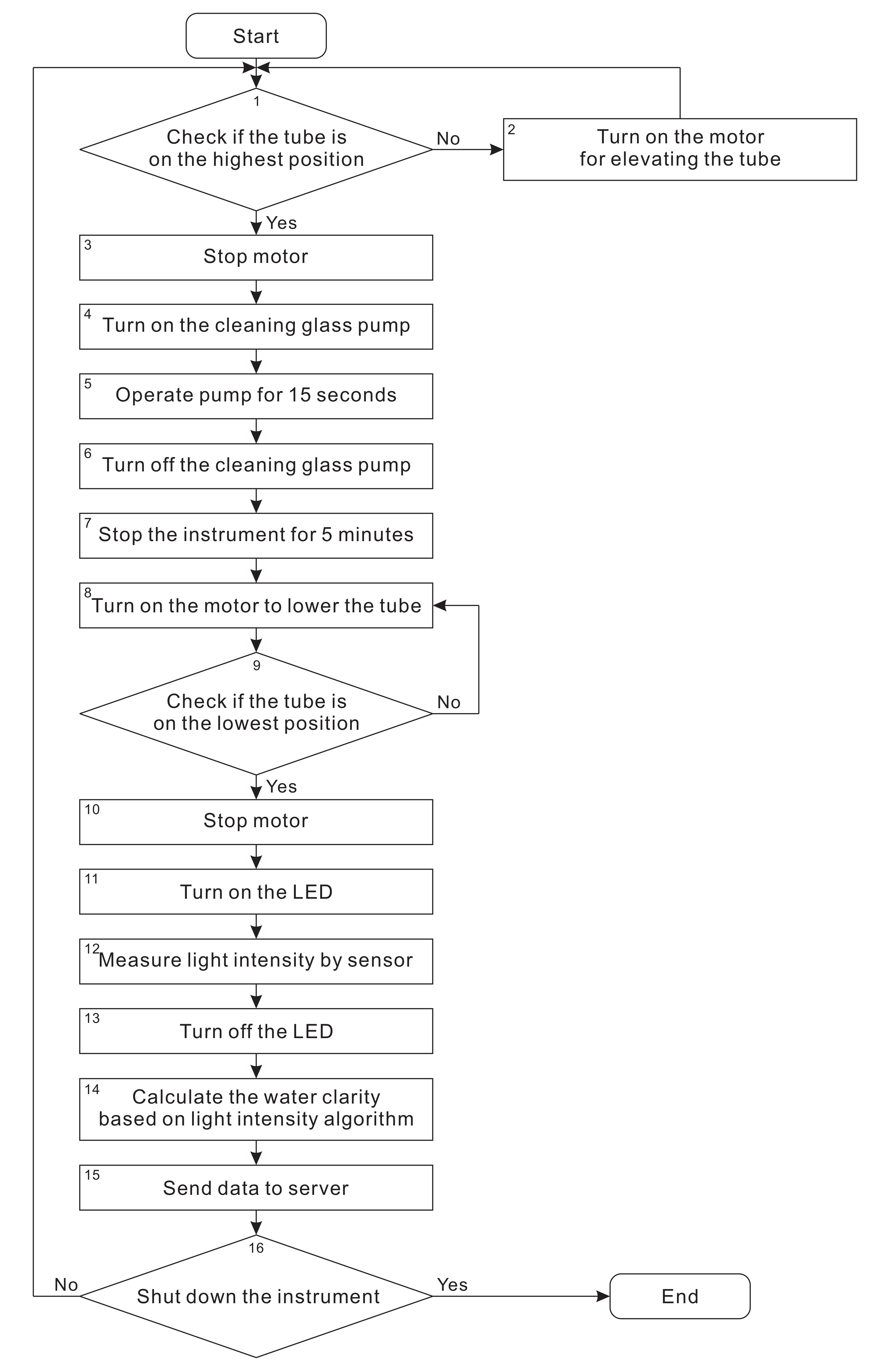
- Step 1:
- Check if the tube is at the highest position. If yes, move to Step 3. Otherwise, move to Step 2.
- Step 2:
- The upper-limit switch remains “open” status when the upper pad does not touch the upper-limit switch’s joint so that the tube keeps elevating until the upper pad touches the joint.
- Step 3:
- When the upper pad touches the upper limit switch’s joint, the controller receives “close” status to turn off the motor.
- Step 4:
- After turning off the motor, the controller operates the mini pump to clean the cover glass of LED box. This process helps to avoid dirty substances on the glass surface which reduces the efficiency fo light transmission.
- Step 5:
- The pump operates for a duration of 15 s. This is the time for the pump to clean the cover glass of LED box.
- Step 6:
- After 15 s, the pump is turned off.
- Step 7:
- As soon as the pump is switched off, the controller stops the instrument for a duration of 5 min. During this period, the current water sample is replaced by a new one. Then, the next measurement result corresponding with the new water sample is recorded.
- Step 8:
- After 5 min, the controller turns on the motor to elevate the tube below water surface to create an isolated measuring environment so that external factors such as weather conditions cannot affect the accurateness of measurement results.
- Step 9:
- Check if the tube is at the ending position or not? If yes, move to Step 10. Otherwise, move back to Step 8.
- Step 10:
- For moving down, the lower-limit switch remains “open” status when the upper pad does not touch the upper-limit switch’s join so that the tube keeps elevating until the upper pad touches the joint. The “open” status is switched to the “close” status. Then, the controller recognizes this event and turns off the motor.
- Step 11:
- Right after turning off the motor, the controller turns on the LEDs to begin the measuring process for the new water sample filled in the tube.
- Step 12:
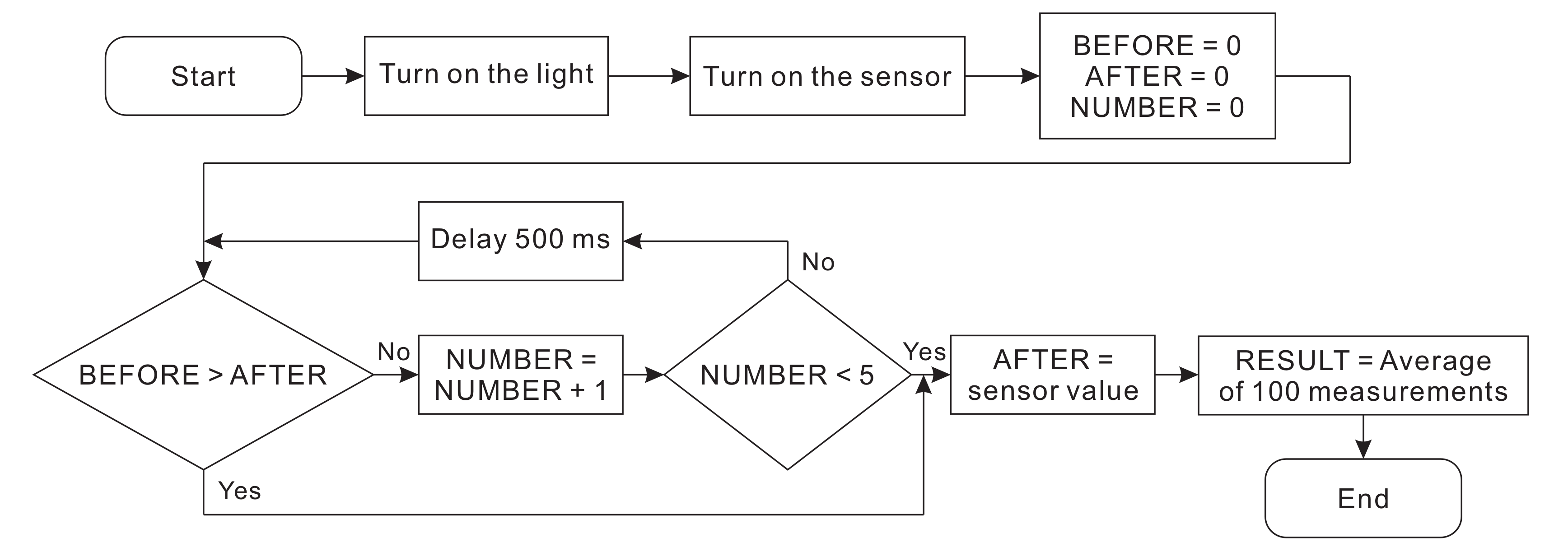
- As long as the LED bulbs are on, the light sensor will capture light intensity passing through the water column.
- Step 13:
- After the controller receives all the results captured by the light sensor, it turns off the LED bulbs and analyzes these results.
- Step 14:
- The controller starts to calculate water clarity by using an algorithm that converts light intensity into ZSD.
- Step 15:
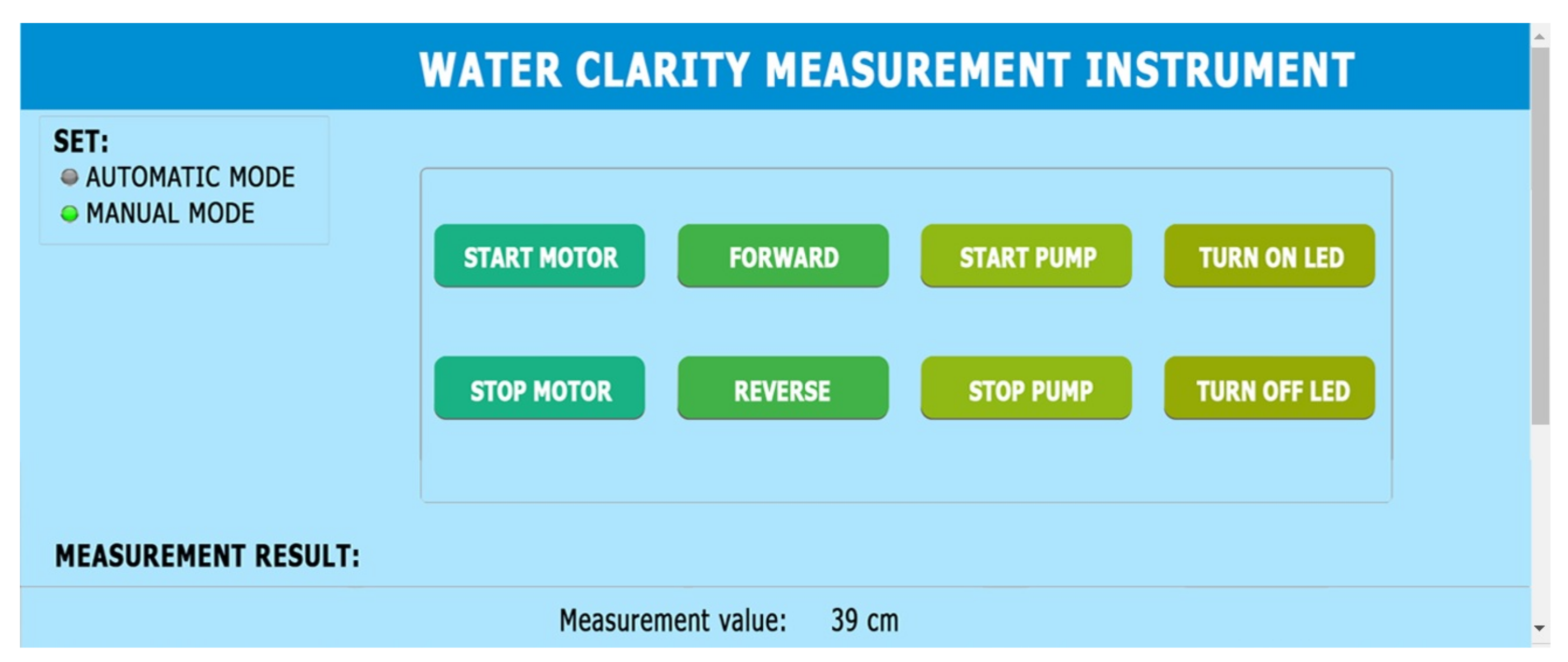
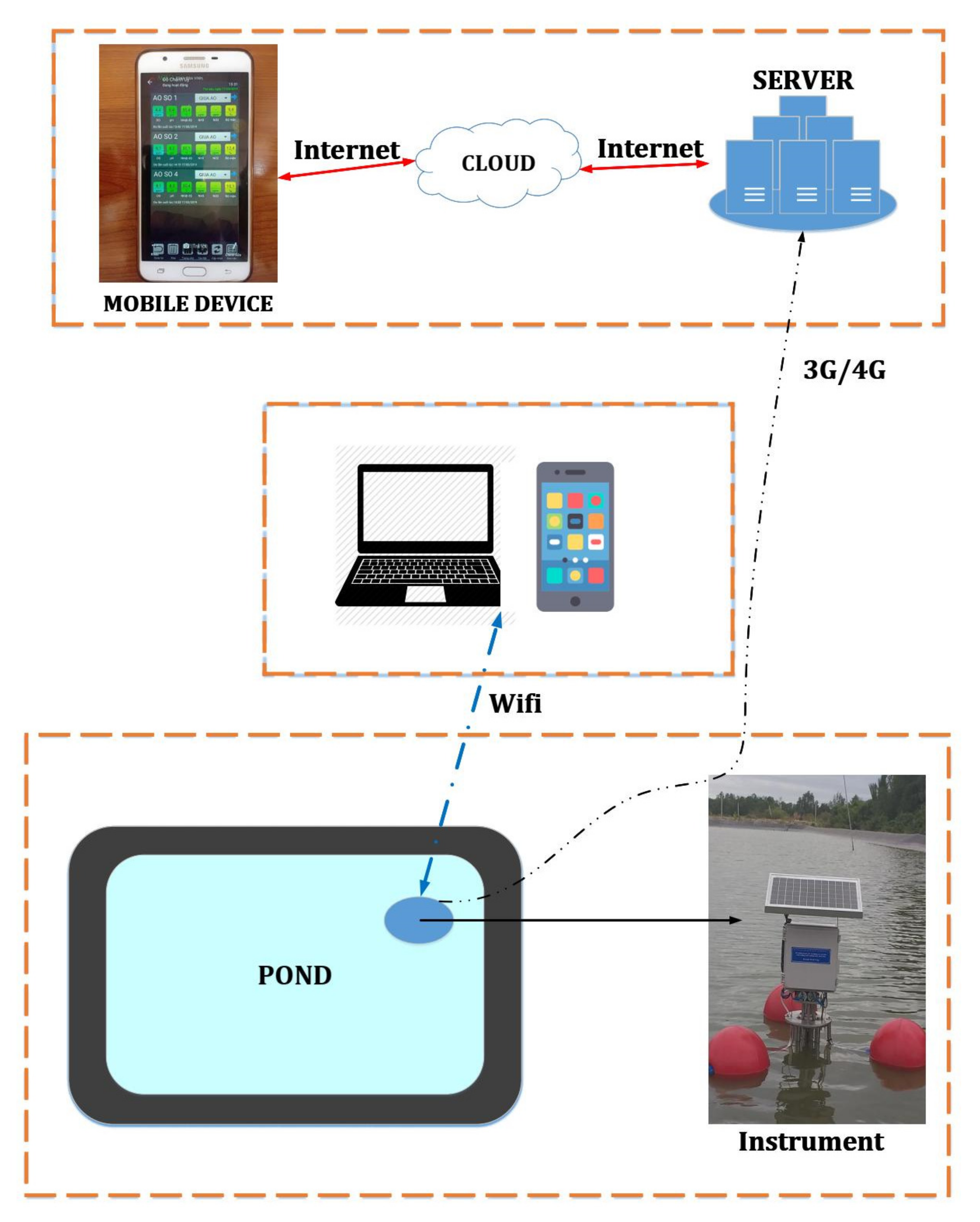
- The controller sends measurement results to server over an Internet connection. Users can monitor these results on computers or mobile phones.
- Step 16:
- The controller repeats the above measuring process according to a fixed routine and shuts down when it receives orders from users.
3. Performance Evaluation of Our Proposed Instrument
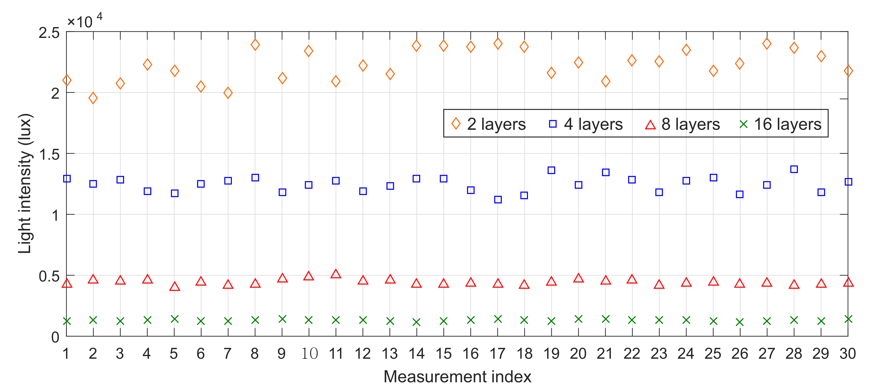
3.1. Experiment of Light Intensity Measurement
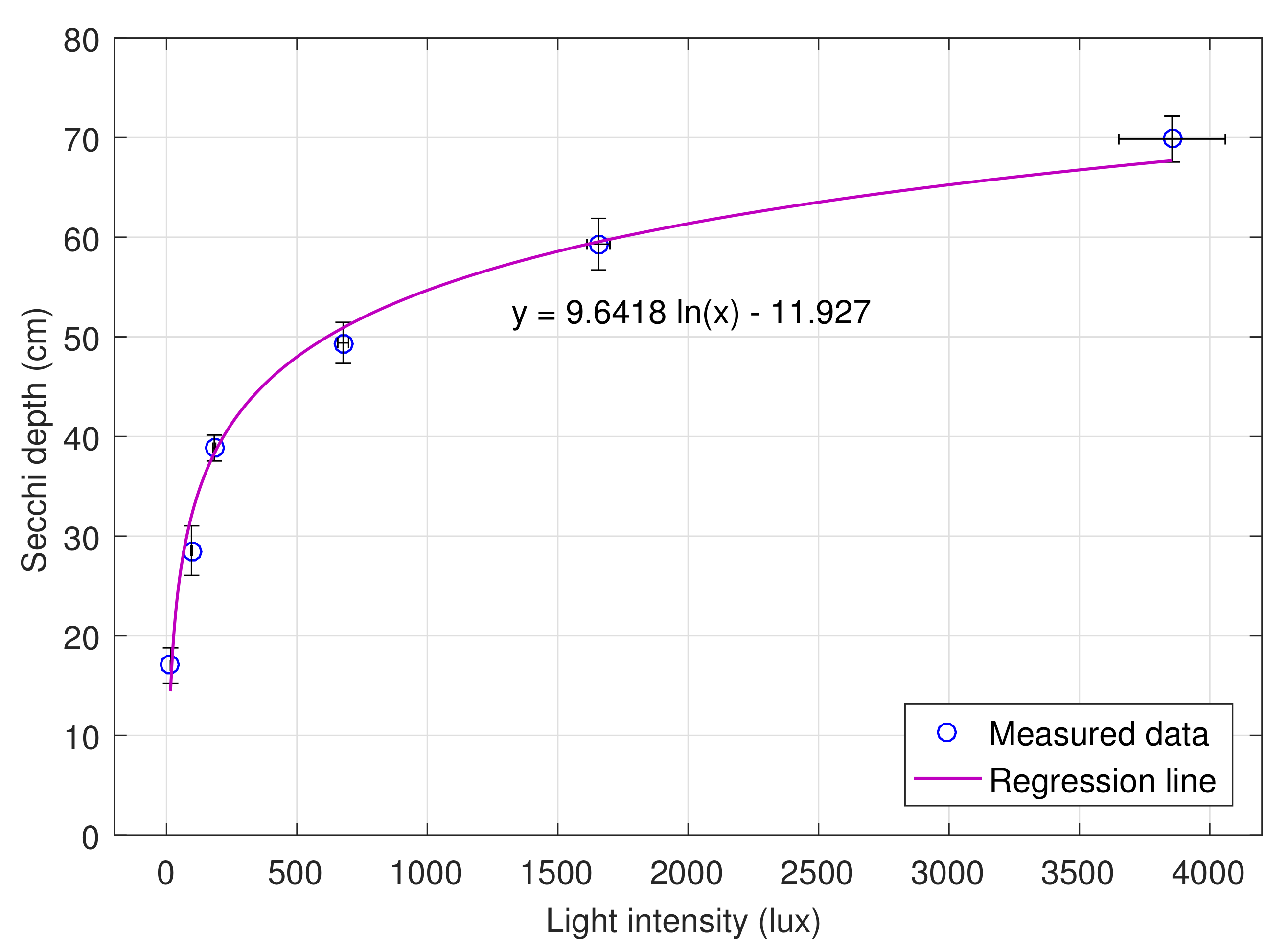
3.2. Experiment for Generating Regression Function
3.3. Experiment with the Instrument in Different Locations
4. Results and Discussion
- Absolute difference is the difference between the ZSD measured by using our instrument and the ZSD measured manually by using Secchi disk, i.e.,
- Percentage difference is the ratio of over , i.e.,
- Average percentage difference is the mean value of “percentage difference”.
4.1. Results of Light Intensity Measurement
4.2. Results of Measurement of Secchi Depth and of Light Intensity by the Instrument to Generate the Regression Function
4.3. Results of ZSD Measured by Secchi Disk and by Instrument in Different Locations
5. Conclusions
Author Contributions
Funding
Conflicts of Interest
References
- Brezonik, P.L.; Bouchard, R.W.; Finlay, J.C.; Griffin, C.G.; Olmanson, L.G.; Anderson, J.P.; Arnold, W.A.; Hozalski, R. Color, chlorophyll α, and suspended solids effects on Secchi depth in lakes: Implications for trophic state assessment. Ecol. Appl. 2019, 29, e01871. [Google Scholar] [CrossRef] [PubMed]
- Li, D.; Liu, S. Water Quality Monitoring and Management: Basis, Technology and Case Studies, 1st ed.; Oxford Academic Press: San Diego, CA, USA, 2019; pp. 18–19. ISBN 978-01-2811-331-8. [Google Scholar]
- State of Narragansett Bay and Its Watershed 2017 Technical Report. Available online: http://nbep.org/01/wp-content/uploads/2017/03/Chapter-17-Water-Clarity.pdf (accessed on 6 April 2020).
- Water Transparency. Available online: https://www.rmbel.info/water-transparency (accessed on 12 February 2020).
- Borowiak, D. Optical Properties of Polish Lakes: The Secchi Disc Transparency. Limnol. Rev. 2015, 14, 131–144. [Google Scholar] [CrossRef] [Green Version]
- Lee, Z.; Shang, S.; Du, K.; Wei, J. Resolving the long-standing puzzles about the observed Secchi depth relationships. Limnol. Oceanogr. 2018, 63, 2321–2336. [Google Scholar] [CrossRef]
- Testa, J.M.; Lyubchich, V.; Zhang, Q. Patterns and Trends in Secchi Disk Depth over Three Decades in the Chesapeake Bay Estuarine Complex. Estuar. Coast. 2019, 42, 927–943. [Google Scholar] [CrossRef]
- Wang, S.; Lee, Z.; Shang, S.; Li, J.; Zhang, B.; Lin, G. Deriving inherent optical properties from classical water color measurements: Forel-Ule index and Secchi disk depth. Opt. Express 2019, 27, 7642–7655. [Google Scholar] [CrossRef]
- Lee, Z.; Shang, S.; Du, K.; Liu, B.; Lin, G.; Wei, J.; Li, X. Enhance field water-color measurements with a Secchi disk and its implication for fusion of active and passive ocean-color remote sensing. Appl. Opt. 2018, 57, 3463–3473. [Google Scholar] [CrossRef]
- Effler, S.W. Secchi Disc Transparency and Turbidity. J. Environ. Eng. 1988, 114, 1436–1447. [Google Scholar] [CrossRef]
- Hou, W.; Lee, Z.; Weidemann, A.D. Why does the Secchi disk disappear? An imaging perspective. Opt. Express 2007, 15, 2791–2802. [Google Scholar] [CrossRef] [Green Version]
- Smith, D.G. A Protocol for Standardizing Secchi Disk Measurements, Including Use of a Viewer Box. Lake Reserv. Manag. 2001, 17, 90–96. [Google Scholar] [CrossRef]
- Tilzer, M. Secchi disk—Chlorophyll relationships in a lake with highly variable phytoplankton biomass. Hydrobiologia 1988, 162, 163–171. [Google Scholar] [CrossRef]
- Davies-Colley, J.R. Measuring water clarity with a black disk. Limnol. Ocean. 1988, 33, 616–623. [Google Scholar] [CrossRef]
- Davies-Colley, R.J.; Smith, D.G. Offsite measurement of the visual clarity of waters. J. Am. Water Resour. As. 1992, 28, 951–957. [Google Scholar] [CrossRef]
- Lee, Z.; Shang, S.; Du, K.; Lin, G.; Liu, T.; Zoffoli, L. Estimating the Transmittance of Visible Solar Radiation in the Upper Ocean Using Secchi Disk Observations. J. Geogr. Res. Ocean. 2019, 124, 1434–1444. [Google Scholar] [CrossRef]
- Aas, E.; Høkedal, J.; Sørensen, K. Secchi depth in the Oslofjord-Skagerrak area: Theory, experiments and relationships to other quantities. Ocean Sci. Discuss 2013, 10, 1833–1893. [Google Scholar] [CrossRef] [Green Version]
- Lee, Z.; Shang, S.; Lin, G.; Liu, T.; Liu, Y.; Du, K.; Luis, K. Secchi disk observation with spectral-selective glasses in blue and green waters. Opt. Express 2017, 25, 19878–19885. [Google Scholar] [CrossRef]
- Almazan, G.; Boyd, C. An evaluation of Secchi disk visibility for estimating plankton density in Fish ponds. Hydrobiologia 1978, 61, 205–208. [Google Scholar] [CrossRef]
- Steel, E.; Neuhausser, S. Comparison of methods for measuring visual water clarity. J. N. Am. Bentho. Soc. 2002, 21, 326–335. [Google Scholar] [CrossRef]
- Harvey, E.; Walve, J.; Andersson, A.; Karlson, B.; Kratzer, S. The Effect of Optical Properties on Secchi Depth and Implications for Eutrophication Management. Front. Mar. Sci. 2019, 5. [Google Scholar] [CrossRef] [Green Version]
- Hoppie, B.; Bronk, T. Construction and first deployment of the JOIDES Resolution’s Secchi discs. Proc. IODP 2011, 329. [Google Scholar] [CrossRef]
- Wernand, M. On the history of the Secchi disc. J. Eur. Opt. Soc. Rapid. 2010, 5. [Google Scholar] [CrossRef] [Green Version]
- Nishijima, W.; Umehara, A.; Sekito, S.; Wang, F.; Okuda, T.; Nakai, S. Determination and distribution of region-specific background Secchi depth based on long-term monitoring data in the Seto Inland Sea, Japan. Ecol. Indic. 2018, 84, 583–589. [Google Scholar] [CrossRef]
- Mayora, G.; Devercelli, M. Spatio-temporal variability in underwater light climate in a turbid river-floodplain system: Driving factors and estimation using Secchi disc. River Res. Appl. 2019, 35, 566–576. [Google Scholar] [CrossRef]
- Sandoval, M.F.; Urrego, E.P.; Verdú, A.R.; Tenjo, C.; Delegido, J.; Perpinyà, X.S.; Vicente, E.; Soria, J.; Moreno, J. Calibration and validation of algorithms for the estimation of chlorophyll-a concentration and Secchi depth in inland waters with Sentinel-2. Limnetica 2019, 38, 471–487. [Google Scholar] [CrossRef]
- Levin, I.; Radomyslskaya, T. Estimate of water inherent optical properties from Secchi depth. Izv. Atmos. Ocean. Phys. 2012, 48, 214–221. [Google Scholar] [CrossRef]
- Effler, S.W.; Strait, C.; O’Donnell, D.M.; Effler, A.J.P.; Peng, F.; Prestigiacomo, A.R.; O’Donnell, S.M.; Perkins, M.; Chapra, S.C. A Mechanistic Model for Secchi Disk Depth, Driven by Light Scattering Constituents. Water Air Soil Pollut. 2017, 228, 153. [Google Scholar] [CrossRef]
- Das, D.; Chakraborty, K.; Pal, S. Colour optimization of the Secchi disk and assessment of the water quality in consideration of light extinction co-efficient of some selected water bodies at Cooch Behar, West Bengal. Int. J. Multidiscip. Res. Dev. 2015, 2, 513–518. [Google Scholar]
- Carruthers, T.J.B.; Longstaff, B.J.; Dennison, W.C.; Abal, E.G.; Aioi, K. References. In Global Seagrass Research Methods, 1st ed.; Short, F.T., Coles, R.G., Eds.; Elsevier: Amsterdam, The Netherlands, 2000; Volume 19, p. 373. ISBN 978-0-0805-2561-7. [Google Scholar]
- Borkman, D.G. Long-term trends in water clarity revealed by Secchi-disk measurements in lower Narragansett Bay. ICES J. Mar. Sci. 1998, 55, 668–679. [Google Scholar] [CrossRef] [Green Version]
- Poor, P.J.; Boyle, K.J.; Taylor, L.O.; Bouchard, R. Objective versus Subjective Measures of Water Clarity in Hedonic Property Value Models. Land Econ. 2001, 77, 482–493. [Google Scholar] [CrossRef]
- Kilroy, C.; Biggs, B.J.F. Use of the SHMAK clarity tube for measuring water clarity: Comparison with the black disk method. N.Z. J. Mar. Freshwat. Res. 2002, 36, 519–527. [Google Scholar] [CrossRef]
- Davies-Colley, R.J.; Smith, D.G. Turbidity suspended sediment, and water clarity: A review. J. Am. Water Resour. As. 2001, 37, 1085–1101. [Google Scholar] [CrossRef]
- Brezonik, P.L. Effect of Organic Color and Turbidity of Secchi Disk Transparency. J. Fish Res. Board Can. 1978, 35, 1410–1416. [Google Scholar] [CrossRef]
- Malik, N.; Date, A.; Leblanc, J.; Akbarzadeh, A.; Meehan, B. Monitoring and maintaining the water clarity of salinity gradient solar ponds. Sol. Energy 2011, 85, 2987–2996. [Google Scholar] [CrossRef]
- Angradi, T.R.; Ringold, P.L.; Hall, K. Water clarity measures as indicators of recreational benefits provided by U.S. lakes: Swimming and aesthetics. Ecol. Indic. 2018, 93, 1005–1019. [Google Scholar] [CrossRef] [PubMed]
- Smith, L.M.; Engle, V.D.; Summers, J.K. Assessing Water Clarity as a Component of Water Quality in Gulf of Mexico Estuaries. Environ. Monit. Assess. 2006, 115, 291–305. [Google Scholar] [CrossRef]
- John, G.M.; Ed, S.; Norman, Y.D.; Mechael, A.T. Use of water clarity to monitor the effect of climate change and other stressors on oligotrophic lakes. Environ. Monit. Assess. 2001, 67, 69–88. [Google Scholar] [CrossRef]
- Kloiber, S.M.; Brezonik, P.L.; Olmanson, L.G.; Bauer, M.E. A procedure for regional lake water clarity assessment using Landsat multispectral data. Remote Sens. Environ. 2002, 82, 38–47. [Google Scholar] [CrossRef]
- Guan, X.; Li, J.; Booty, W.G. Monitoring Lake Simcoe Water Clarity Using Landsat-5 TM Images. Water Resour. Manag. 2001, 25, 2015–2033. [Google Scholar] [CrossRef]
- Olmanson, L.G.; Brezonik, P.L.; Finlay, J.C.; Bauer, M.E. Comparison of Landsat 8 and Landsat 7 for regional measurements of CDOM and water clarity in lakes. Remote Sens. Environ. 2016, 185, 119–128. [Google Scholar] [CrossRef]
- Zhao, D.; Cai, Y.; Jiang, H.; Xu, D.; Zhang, W.; An, S. Estimation of water clarity in Taihu Lake and surrounding rivers using Landsat imagery. Adv. Water Resour. 2011, 34, 165–173. [Google Scholar] [CrossRef]
- Palandro, D.; Hu, C.; Andréfouët, S.; Muller-Karger, F.E. Synoptic water clarity assessment in the Florida Keys using diffuse attenuation coefficient estimated from Landsat imagery. Hydrobiologia 2004, 530, 489–493. [Google Scholar] [CrossRef]
- Anassontzis, E.G.; Ball, A.E.; Belias, A.; Fotiou, A.; Grammatikakis, G.; Kontogiannis, H.; Koske, P.; Koutsoukos, S.; Lykoussis, V.; Markopoulos, E.; et al. Water transparency measurements in the deep Ionian Sea. Astropart. Phys. 2010, 34, 187–197. [Google Scholar] [CrossRef] [Green Version]
- Allocca, D.M.; London, M.A.; Curran, T.P.; Concannon, B.M.; Contarino, M.V.; Prentice, J.; Mullen, L.J.; Kane, T.J. Ocean water clarity measurement using shipboard lidar systems. In Proceedings of the Ocean Optics: Remote Sensing and Underwater Imaging, San Diego, CA, USA, 14 January 2002; Volume 4488, pp. 106–114. [Google Scholar]
- Lambrou, T.P.; Anastasiou, C.C.; Panayiotou, C.G. A Nephelometric Turbidity System for Monitoring Residential Drinking Water Quality. In Proceedings of the International Conference on Sensor Applications, Experimentation and Logistics, Athens, Greece, 25 September 2009; Springer: Cham, Switzerland, 2009; Volume 29, pp. 43–55. [Google Scholar] [CrossRef]
- Wijnen, B.; Anzalone, G.C.; Pearce, J.M. Open-source mobile water quality testing platform. J. Water Sanit. Hyg. Dev. 2014, 4, 532–537. [Google Scholar] [CrossRef]


| Experiment | First Experiment | Second Experiment | Third Experiment | Fourth Experiment | Fifth Experiment | Sixth Experiment | ||||||
|---|---|---|---|---|---|---|---|---|---|---|---|---|
| No. | ZSD | LI | ZSD | LI | ZSD | LI | ZSD | LI | ZSD | LI | ZSD | LI |
| 1 | 15.5 | 14 | 28.5 | 94 | 38 | 192 | 50.5 | 660 | 57.5 | 1615 | 67.5 | 4149 |
| 2 | 16.5 | 16 | 27.5 | 100 | 37.5 | 189 | 47.5 | 661 | 59.5 | 1716 | 69 | 3987 |
| 3 | 14.5 | 15 | 24.5 | 96 | 38.5 | 183 | 52 | 643 | 58.5 | 1635 | 72 | 3532 |
| 4 | 15 | 14 | 31.5 | 96 | 39 | 190 | 48 | 652 | 60.5 | 1598 | 68 | 4015 |
| 5 | 20 | 16 | 28.5 | 97 | 39.5 | 181 | 50 | 678 | 63 | 1637 | 67 | 3884 |
| 6 | 16.5 | 15 | 28.5 | 95 | 41 | 179 | 52 | 704 | 57.5 | 1662 | 69.5 | 3647 |
| 7 | 18 | 16 | 27 | 93 | 40 | 177 | 46.5 | 691 | 64.5 | 1713 | 72 | 3582 |
| 8 | 20 | 17 | 32.5 | 96 | 37.5 | 182 | 48.5 | 688 | 57.5 | 1677 | 73.5 | 3749 |
| 9 | 17.5 | 15 | 31.5 | 94 | 40.5 | 180 | 52 | 701 | 55.5 | 1599 | 67.5 | 4036 |
| 10 | 16.5 | 16 | 25.5 | 97 | 37 | 177 | 47 | 695 | 59 | 1710 | 72.5 | 3937 |
| Mean | 17 | 15.4 | 28.55 | 95.8 | 38.85 | 183.0 | 49.4 | 677.3 | 59.3 | 1656.2 | 69.85 | 3855.4 |
| Standard deviation | 1.8 | 0.92 | 2.49 | 1.9 | 1.3 | 5.18 | 2.06 | 20.7 | 2.59 | 44.0 | 2.3 | 204 |
| CV (%) | 10.59 | 5.95 | 8.72 | 2.0 | 3.35 | 2.83 | 4.17 | 3.05 | 4.37 | 2.7 | 3.29 | 5.3 |
| Location | Can Gio District, Ho Chi Minh City | Vinh Chau District, Soc Trang Province | Gia Rai District, Bac Lieu Province | ||||||
|---|---|---|---|---|---|---|---|---|---|
| Measurement | ZSD, cm | ZSD, cm | ZSD, cm | ||||||
| Reservoir | Shrimp Pond | Wastewater Pond | Reservoir | Shrimp Pond | Wastewater Pond | Reservoir | Shrimp Pond | Wastewater Pond | |
| Using the Secchi disk | 47 | 38 | 28 | 52 | 41 | 25 | 43 | 35 | 26 |
| Using the instrument | 46.75 | 37.28 | 27.2 | 53.4 | 40.36 | 24.13 | 45.1 | 35.72 | 25.4 |
| Absolute difference | 0.25 | 0.72 | 0.8 | 1.4 | 0.64 | 0.87 | 2.1 | 0.72 | 0.6 |
| Percentage difference | 0.53 | 1.90 | 2.90 | 2.69 | 1.56 | 3.48 | 4.88 | 2.05 | 2.30 |
| Location | Thanh Phu District, Ben Tre Province | Duyen Hai District, Tra Vinh Province | Cai Nuoc District, Ca Mau Province | ||||||
|---|---|---|---|---|---|---|---|---|---|
| Measurement | ZSD, cm | ZSD, cm | ZSD, cm | ||||||
| Reservoir | Shrimp Pond | Wastewater Pond | Reservoir | Shrimp Pond | Wastewater Pond | Reservoir | Shrimp Pond | Wastewater Pond | |
| Using the Secchi disk | 59 | 43 | 22 | 40 | 33 | 19 | 55 | 41 | 28 |
| Using the instrument | 58.1 | 41.8 | 21.3 | 39.75 | 37.28 | 18.2 | 54.3 | 40.4 | 27.7 |
| Absolute difference | 0.9 | 1.2 | 0.7 | 0.25 | 0.72 | 0.8 | 0.7 | 0.6 | 0.3 |
| Percentage difference | 1.53 | 2.79 | 3.18 | 0.53 | 1.90 | 2.90 | 1.27 | 1.46 | 1.07 |
© 2020 by the authors. Licensee MDPI, Basel, Switzerland. This article is an open access article distributed under the terms and conditions of the Creative Commons Attribution (CC BY) license (http://creativecommons.org/licenses/by/4.0/).
Share and Cite
Pham, T.N.; Ho, A.P.H.; Nguyen, T.V.; Nguyen, H.M.; Truong, N.H.; Huynh, N.D.; Nguyen, T.H.; Dung, L.T. Development of a Solar-Powered IoT-Based Instrument for Automatic Measurement of Water Clarity. Sensors 2020, 20, 2051. https://0-doi-org.brum.beds.ac.uk/10.3390/s20072051
Pham TN, Ho APH, Nguyen TV, Nguyen HM, Truong NH, Huynh ND, Nguyen TH, Dung LT. Development of a Solar-Powered IoT-Based Instrument for Automatic Measurement of Water Clarity. Sensors. 2020; 20(7):2051. https://0-doi-org.brum.beds.ac.uk/10.3390/s20072051
Chicago/Turabian StylePham, Tuan Ngoc, Anh Pham Huy Ho, Tuong Van Nguyen, Ha Minh Nguyen, Nhu Huynh Truong, Nguyen Duc Huynh, Tung Huy Nguyen, and Le The Dung. 2020. "Development of a Solar-Powered IoT-Based Instrument for Automatic Measurement of Water Clarity" Sensors 20, no. 7: 2051. https://0-doi-org.brum.beds.ac.uk/10.3390/s20072051