Implementation of Neuro-Memristive Synapse for Long-and Short-Term Bio-Synaptic Plasticity


1
Division of Electronics and Information Engineering and Core Research Institute of Intelligent Robots, Jeonbuk National University, Jeonju 567-54896, Korea
2
Division of Electronics Engineering and Core Research Institute of Intelligent Robots, Jeonbuk National University, Jeonju 567-54896, Korea
3
Department of Electrical Engineering and Computer Sciences, University of California, Berkeley, CA 94720-1770, USA
*
Author to whom correspondence should be addressed.
Sensors 2021, 21(2), 644; https://0-doi-org.brum.beds.ac.uk/10.3390/s21020644
Submission received: 27 December 2020
/
Revised: 12 January 2021
/
Accepted: 14 January 2021
/
Published: 18 January 2021
(This article belongs to the Section Biomedical Sensors)
Abstract
:In this paper, we propose a complex neuro-memristive synapse that exhibits the physiological acts of synaptic potentiation and depression of the human-brain. Specifically, the proposed neuromorphic synapse efficiently imitates the synaptic plasticity, especially long-term potentiation (LTP) and depression (LTD), and short-term facilitation (STF) and depression (STD), phenomena of a biological synapse. Similar to biological synapse, the short- or long-term potentiation (STF and LTP) or depression (STD or LTD) of the memristive synapse are distinguished on the basis of time or repetition of input cycles. The proposed synapse is also designed to exhibit the effect of reuptake and neurotransmitters diffusion processes of a bio-synapse. In addition, it exhibits the distinct bio-realistic attributes, i.e., strong stimulation, exponentially decaying conductance trace of synapse, and voltage dependent synaptic responses, of a neuron. The neuro-memristive synapse is designed in SPICE and its bio-realistic functionalities are demonstrated via various simulations.
1. Introduction
Effort is being made to develop a highly technical and specialized artificial intelligence that exhibits human brain-like intelligence. These bioinspired neuromorphic circuits are considered as the new computing platform which outperforms conventional Von-Neumann architectures, as it owns features such as high efficiency, low power consumption, higher adaptability, and enormous parallel processing [1]. Recent technical advances in nano-scale complementary metal oxide semiconductor (CMOS) technologies facilitate researchers to design large-scale neuromorphic circuits utilizing specific very large-scale integration (VLSI) hardware. Additionally, it eases the process of designing complex brain-like intelligence and eventually contributes to connect the human brains directly with machines [2,3]. Recently, researchers developed neuromorphic chips based on CMOS [4,5], subthreshold CMOS [6], OxRAM [7], switched-capacitor (SC) [8], spintronic [9], and memristive [10,11,12,13,14,15] technologies. Among these, memristor is regarded as one of the most potential candidates for designing neuromorphic ICs due to its unique features of bio-synapse, such as operation, low energy consumption, multiple-state operation, impressive scalability, and CMOS compatibility [16].
Inspired with such technological advances, in this literature, we propose a complex neuro-memristive synapse that exhibits the physiological acts of synaptic plasticity of human brain. The proposed memristive synapse impersonates both synaptic potentiation (short-term facilitation (STF) and long-term potentiation (LTP)) and depression (short-term depression (STD) and long-term depression (LTD)) phenomena. Moreover, it is also designed to exhibit the outcome of reuptake and neurotransmitter diffusion processes (i.e., memory fading effect (MFE) in the electronic circuit) of a biological synapse along with the bio-realistic attributes of a neuron. In re-uptake and neurotransmitters diffusion processes, the number of released neurotransmitters of a biological synapse are decreased and eventually result in a decrement of synaptic strength which can be related to the memory fading effect of electronic circuit and also of the human brain.
To accommodate such diverse biological attributes, the neuro-memristive synapse is designed with a composite 1-port of memristor (M) and a controlled capacitor (CCon). The memristance and voltage across the memristor act as the artificial synaptic strength and voltage, respectively. The CCon capacitor controls the rate of discharging through memristor (M). In potentiation (active cycle of input stimulation), the composite 1-port is charged whereas the memristor of 1-port is partially or fully discharged in the inactive cycle of stimulation based on the active presence of MFE or depression signals. Similar to biological synapse, the short- or long-term potentiation (STF and LTP) or depression (STD and LTD) of artificial synapse are distinguished based on the time or repetition of input cycle. However, the rate of decrement in synaptic strength for SMF and depression are quite different. Hence, the dissimilar rate of change in synaptic efficacy is designed with two different MOS switches. In addition, after a successive STF or LTP process, the rate of removal of neurotransmitters from synapse for reuptake or diffusion (MFE effect) are quite different. Therefore, separate discharging paths are designed through CCon that facilitate the partial discharging through memristor (M).
The neuromorphic excitatory synapses presented in [4] requires twice more hardware than our proposed synapse to implement only spike-timing dependent plasticity (STDP). The digital-controlled neuromorphic circuit in [5] requires additional circuits to implement synaptic plasticity than the self-sufficient proposed model, hence it is less compatible and area inefficient. The sub-threshold CMOS iono-neuromorphic model in [6] requires a nonvolatile digital storage to store synaptic modification and unable to exhibit short-term synaptic plasticity compared to the proposed memristive synapse. To imitate the STP and LTP phenomena, the proposed neuro-memristive synapse requires only a single memristor unlike the OxRAM synapse in [7] which requires 10 and 20 OxRAM devices, respectively. Moreover, the proposed synapse is bio-realistically more effective, energy and area efficient than the switched-capacitor based conductive synapse in [8] which requires multiple switches, couple of capacitors, and amplifier to implement a single synaptic conductance. The proposed memristive synapse is implemented in circuit with off-the-shelf components unlike the mathematical [11] and macro [12] model of memristive synapse. In addition, the proposed memristive synapse is energy and area efficient compared to CMOS-memristive [13] and excitatory memristive [14] synapses despite of exhibiting more bio-synaptic attributes.
The main advantage of the proposed architecture is that the analog artificial synapse can be utilized in both volatile and nonvolatile configuration with a single memristor, unlike prior literatures which required multiple memory elements. Utilizing the synapse alike operation of memristor, the neuro-memristive synapse can also exhibit the bio-realistic attributes of a neuron along with synaptic plasticity. Since the conductance-based neuromorphic synaptic architecture overcomes the limitations of subthreshold analog- and transistor-based CMOS neural circuits and conventional Von-Neumann architectures, it facilitates to port the proposed design in miniature CMOS ICs.
The neuro-memristive synapse can be used to design spiking neural networks with Hebbian or anti-Hebbian learning algorithms. It can also be utilized in academia to analyze the synaptic functionalities of neuron instead in-vivo or in-vitro analysis, and in future the industrial design might be used to design the human brain-like intelligence.
Rest of the paper is organized as following: the biological background of synaptic transmission and plasticity are described in Section 2 and the working principle of proposed artificial synapse is discussed in Section 3. The simulations and results are presented in Section 4 followed by the concluding remarks in Section 5.
2. Neuronal Transmission and Synaptic Plasticity
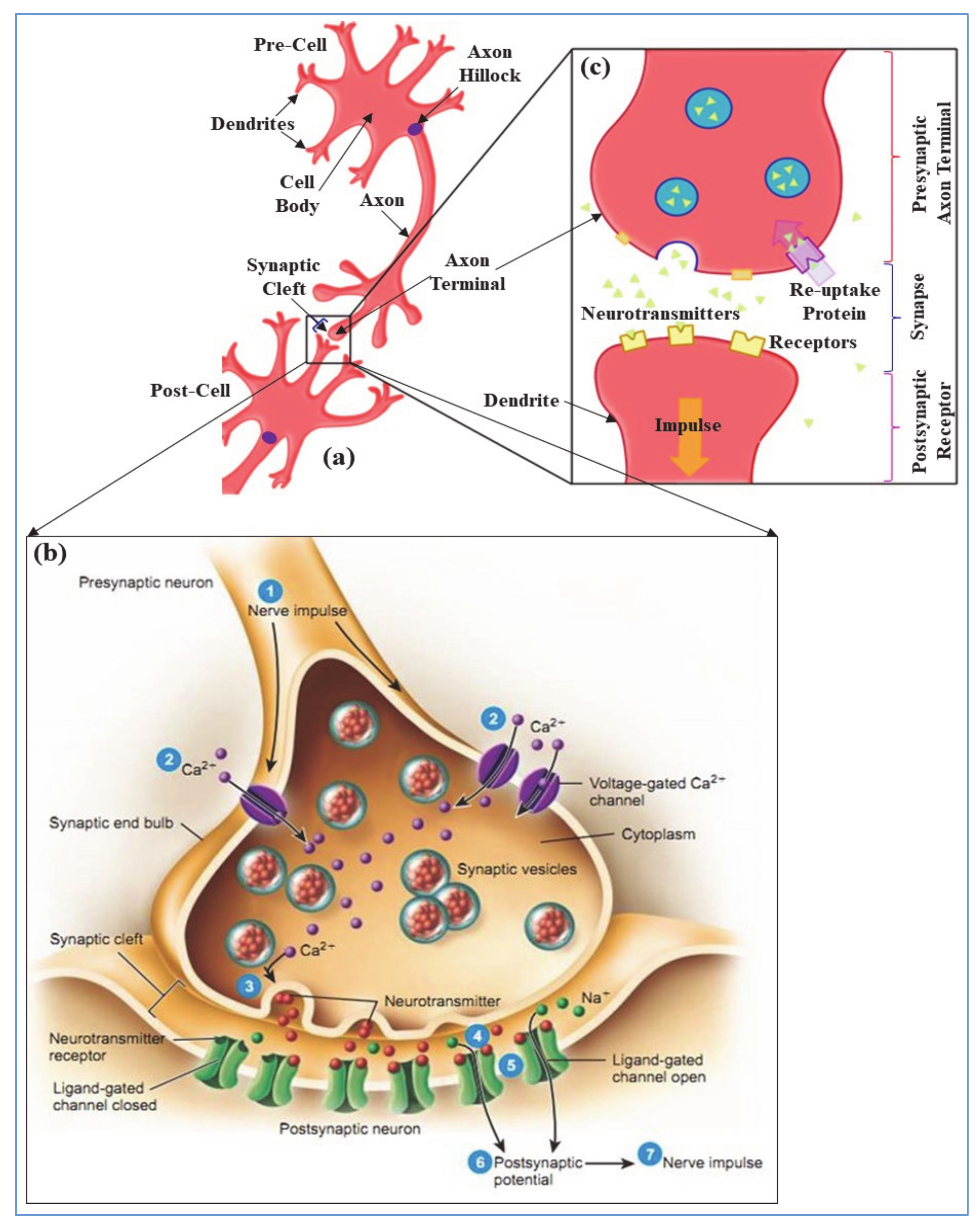
In neurobiology, electrically excitable neurons or cells are transmitting information via synapses. The electro-chemical synaptic transmission among neurons is established when the presynaptic axon terminal (shown in Figure 1a) is depolarized with the arrival of axon-hillock generated action potential (AP) or nerve impulse [17]. Thus, the membrane potential of pre-axon terminal is changed which initiates the opening of voltage gated calcium (Ca2+) nano-pore ion channels as shown in Figure 1b. The extracellular Ca2+ ions infiltrate to the presynaptic membrane because of steep concentration gradients. Penetrated intracellular Ca2+ influx allows the synaptic vesicles to fuse with the presynaptic plasma membrane and release the neurotransmitters in synaptic cleft [18]. The Synaptic cleft, shown in Figure 1b, is a small gap between pre- and post-synaptic neurons (≈20 nm wide) and forms a junction between neurons. The molecules of a released neurotransmitter, in Figure 1b, diffuse across the synaptic cleft and bind to the postsynaptic receptor proteins. Hence, this activates the postsynaptic receptors and leads to the opening or closing of ligand-gated ion channels in post cell. The type of released neurotransmitters have effect on the channel behavior that determines the outcome of postsynaptic cell [19]. For example, acetylcholine (ACh) or glutamate neurotransmitters depolarize (i.e., make the inside of the cell more positive than resting membrane potential) the post-cell and increase the probability of postsynaptic firings. In contrast, GABA or dopamine neurotransmitters hyperpolarize (i.e., make the inside of the cell more negative than resting membrane potential) the post-cell and oppress the post firings. In this paper, we discussed about the excitatory ACh neurotransmitter and its synaptic transmission events. For ACh neurotransmitters, the postsynaptic receptor leads to the opening of sodium (Na+) ion channels and the extracellular Na+ ions infiltrate into post cell membrane due to concentration gradients. Therefore, the postsynaptic neuron depolarizes, and rises up the cell membrane potential from resting potential, typically −70 mV~−90 mV. When the post membrane potential reaches threshold (typically −55 mV) then it generates an all-or-none electrical impulse (i.e., action potential) and reaches the peak voltage around +40 mV [20]. At peak, the post cell membrane initiates to close Na+ ion channels whereas open potassium (K+) ion channels (shown in Figure 1b), and intracellular K+ ions are moving out of the cell, known as repolarization [21]. The post cell membrane continues to repolarize because of the permeability of K+ ion channels and results in an undershoot which is lower than the resting membrane potential, known as hyperpolarization. The membrane potential gradually recovers the undershoot and stabilizes to resting membrane potential [17].
Generation of postsynaptic action potentials in chemical synaptic transmission is proportional to the probability and pattern of neurotransmitter release, and the receptor sensitization of postsynaptic neuron [22,23]. In contrast, after successive transmission of a neural impulse, reuptake process reabsorbs the diffused neurotransmitters from synaptic cleft through a neurotransmitter transporter and brings back to pre-cell membrane as shown in Figure 1c. Reuptake allows the recycling of neurotransmitters and regulates the level of presence of neurotransmitter in synapse which is essential for normal synaptic physiology. Thereby, it controls the lasting durability of released neurotransmitters that results from an excitation [24]. However, in the diffusion process neurotransmitters are detached from the post receptors, drifting out of the synaptic cleft by breaking down with specific enzymes, and absorbed by pre-glial cells for resynthesizing to new neurotransmitters. Both the reuptake and diffusion process decreases the synaptic efficacy of a successive neuronal communication by removing the chemical messenger (i.e., neurotransmitters) from the synaptic cleft [19]. This self-removal mechanism of the neurotransmitters after successive transmissions of a neural impulse can be related to the memory fading effect in the electronic circuit.
Synaptic plasticity is the ability of a synapse to modify its strength or efficacy over a certain period of time. Depending upon the durability of synaptic modification, plasticity is categorized in two types: short-term plasticity and long-term plasticity. Short-term plasticity lasts only for a couple of minutes or less whereas long-term plasticity persists for hours, months or even years [19]. Moreover, based on synaptic modification, short- and long-term plasticity are classified as: short-term potentiation or facilitation (STF) and depression (STD), and long-term potentiation (LTP) and depression (LTD). Both STF and LTP strengthen the synapse in accordance with the perishable release of presynaptic neurotransmitters. Contrarily, STD and LTD weaken the synapse by blocking the neurotransmitters release in spite the presence of presynaptic stimulus, and remove the neurotransmitters from synaptic cleft [19].
STF initiates with close successive presynaptic stimulations that release a higher amount of neurotransmitters, and swiftly strengthen the synapse for a shorter period of time [25]. Unlike STF, LTP persistently strengthens the synapse depending upon the recent patterns of synaptic activity. It produces a long-lasting synaptic enhancement between two neurons by secreting an enormous number of neurotransmitters in the synaptic cleft [26]. Both STF and LTP are considered as one of the major neuromorphic foundations of learning and memory in neuronal communication, as memories are thought to be encoded by the modification of synaptic strength [27].
STD induces with the depletion of neurotransmitter vesicles despite the presence of presynaptic stimulations and weakens the synaptic efficacy (i.e., strength) over a short period of time [25]. However, LTD refers to an activity-dependent reduction in the synaptic efficacy that lasts hours or longer based on the patterns of stimulation. It selectively weakens the synapses disregard of presynaptic stimulation, and builds a productive use of synaptic strengthening caused by LTP. Moreover, it facilitates encoding of new information by stabilizing the neuronal circuit [27].
3. Artificial Neuro-Memristive Synapse
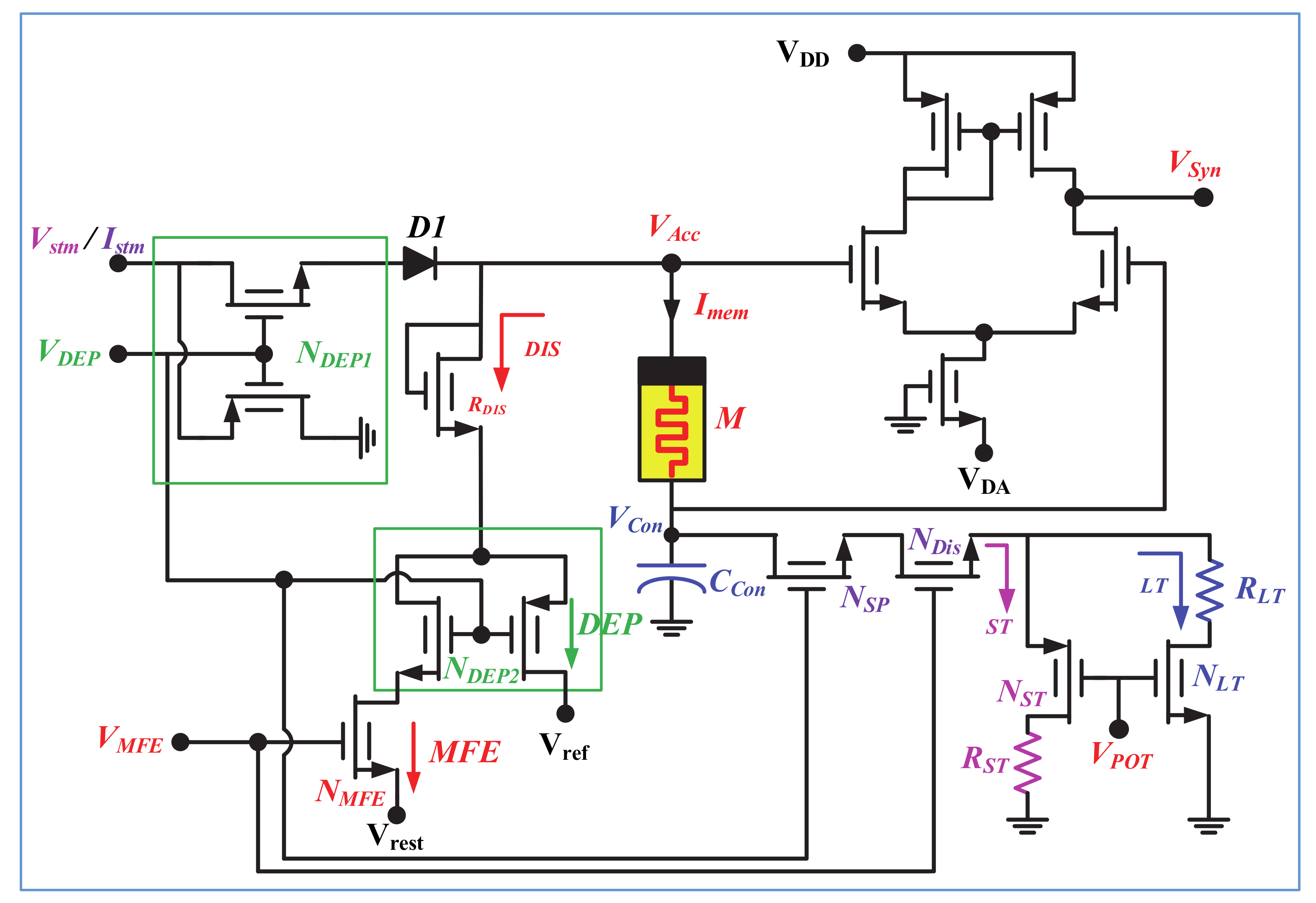
The neuro-memristive synapse, shown in Figure 2, is designed with a composite 1-port of memristor and capacitor to incorporate the bio-diverse attributes of synaptic plasticity. Memristor [28] is used to imitate the bio-realistic functionalities of a synapse whereas capacitor is utilized to control the partial or full discharging through memristor (M). A depression switch (NDEP1) is used to regulate the input of memristor where diode (D1) is used to block the reverse current. NDEP1 decides between the potentiation (VDEP = high) or depression (VDEP = low) mode of operation of the proposed memristive synapse and controls the flowing of input current (Istm) through the composite 1-port which is defined as:
The memristance of the memristor can be determined as:
where M(0) = Rs is the initial state, and VCT and RT are the intrinsic parameters of the memristor, respectively (Section S1 of Supplementary Materials).
The volatile memory fading effect (i.e., neurotransmitter diffusion or reuptake processes of bio-synapse) is designed with a discharging path through MOS resistor RDIS. The synaptic weakening process of a bio-synapse for reuptake or diffusion, and depression mechanisms are quite dissimilar and could not occur at once. Thus, two separate discharging paths are included through RDIS resistor which is controlled by a secondary depression switch NDEP2 and memory fading switch NMFE. For a high VMFE and VDEP, the neuro-memristive synapse will operate in MFE mode and the memristor (M) will discharge through NMFE switch (as shown with red arrowhead). Contrarily, for low VDEP, the proposed memristive synapse will exhibit depression irrespective of VMFE, and discharges through NDEP2 switch (as shown with green arrowhead). Moreover, according to biology, the rate of removal of neurotransmitters from synaptic cleft slows down with high frequency repetitive or rhythmic stimulations (i.e., STF or LTP) that results in slower weakening of bio-synapse. Therefore, the synaptic weakening process of a LTP exhibiting synapse is the slowest than that of STF and normal synaptic response (NSR) exhibiting synapse. This dynamic synaptic weakening attributes of synapse is incorporated with a separated discharge path through control capacitor CCon. The discharging path is activated in the inactive cycle of input (i.e., active period of VMFE) and further regulates with synaptic plasticity switch NSP. When VMFE = high and VDEP = high (i.e., no synaptic depression), the capacitor (CCon) will partially discharge through memristor and mostly discharge through NST or NLT switch depending upon VPOT. The rate of discharging through NLT is higher than NST. For example, if the neuro-memristive synapse exhibits LTP in active cycle and MFE in inactive cycle with VDEP = high, then the CCon capacitor mostly discharge through NLT (with high VPOT) and partially discharge through memristor. Hence, the neuro-memristive synapse will exhibit dissimilar synaptic weakening (i.e., dissimilar rate of removal of neurotransmitters) depending on NSR, STF, and LTP exhibiting phenomena. However, for VMFE = high and VDEP = low (i.e., active presence of synaptic depression), the CCon capacitor will fully discharge through memristor and there exists no discharging through NST or NLT. In addition, the memristive synapse can be operated in nonvolatile configuration by oppressing the VMFE and VDEP signals. Output of the proposed synapse (VSyn) is obtained across the memristor using a CMOS differential amplifier and determined as:
where the biasing current of CMOS amplifier depends on the input stimulation. The proposed synapse is operable with both current and voltage input, however, the optimal performance is achieved with current stimulation (Section S2 of the Supplementary Materials). For voltage stimulation, the reference voltage of CMOS amplifier VDA = −Vin whereas for current stimulation VDA = −Iin × (RL = 10 KΩ). The operating modes of proposed neuro-memristive synapse is included in Table 1.
4. Results and Simulations
The bio-realistic features of the proposed neuro-memristive synapse are verified with various SPICE simulations. Due to the commercial unavailability of memristor, a realistic and diverse memristor emulator [28] is used to design the neuro-memristive synapse. To avoid the unintended consequences of nonlinear ionic dopant drift (Section S1 of Supplementary Materials) at boundaries of a memristor [29,30,31], we follow the common practice of initializing the memristance of a memristor in a linear region (2 KΩ~14 KΩ) [32,33]. Therefore, we initialized our memristor emulator at M(0) = 2 KΩ and limit its operation within the linear region. The circuit parameters used to obtain the experimental results are enlisted in Table 2.
4.1. Normal Synaptic Response (NSR)
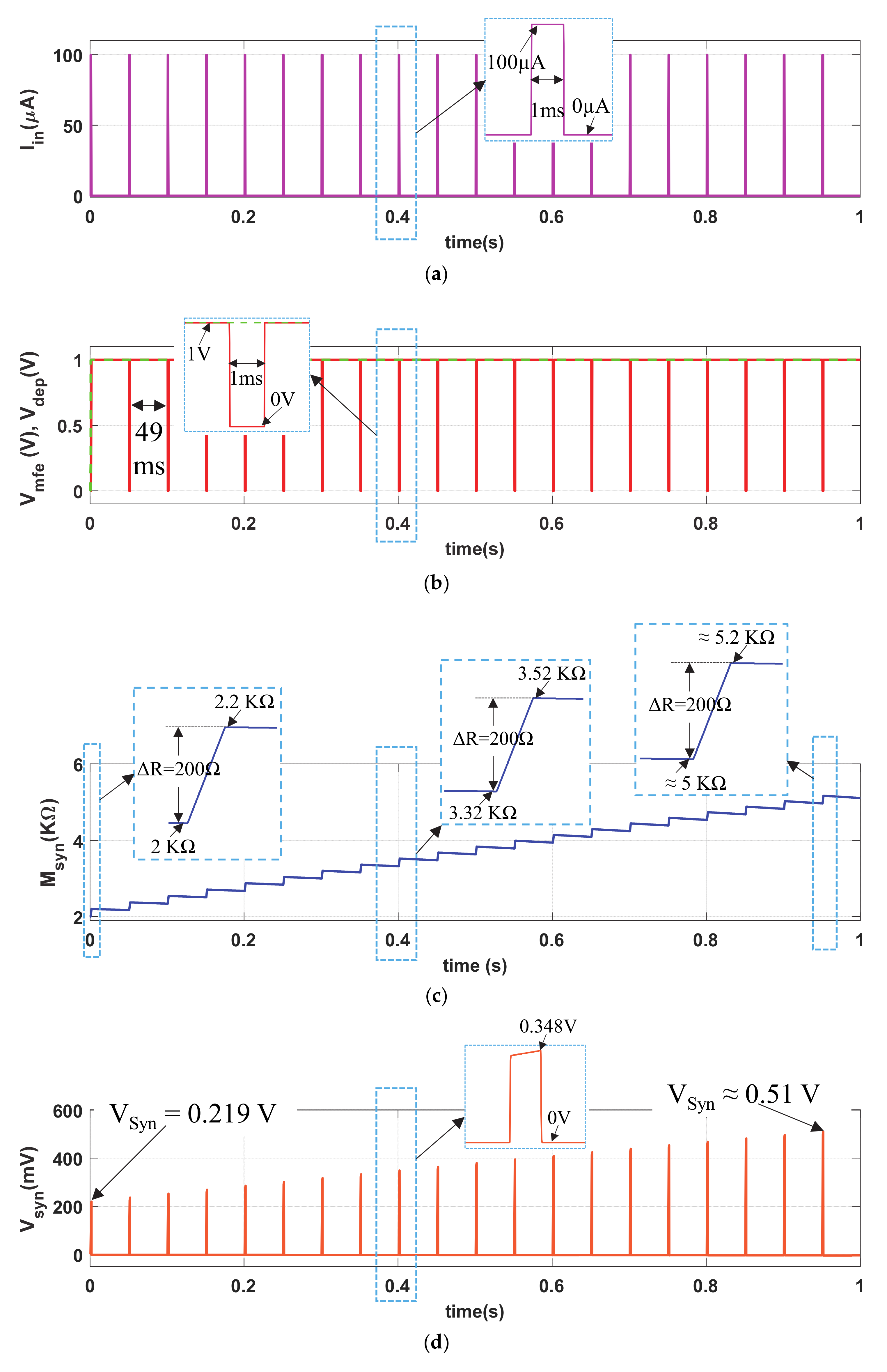
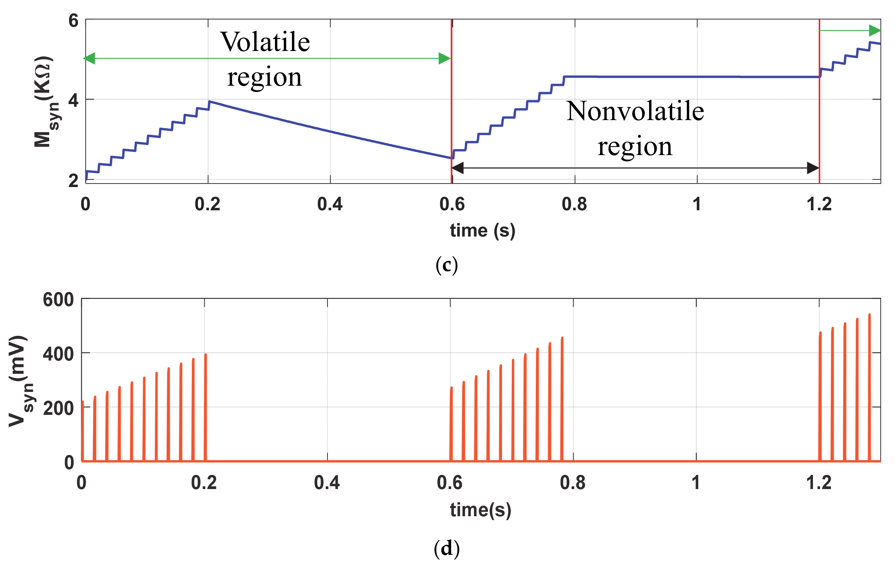
The normal synaptic response (NSR) is demonstrated with a pulse current input Iin (pulse amplitude PA = 100 µA, pulse width PW = 1 ms and pulse period PP = 50 ms) with a duty ratio of 2%, shown in Figure 3a. We chose the pulse width PW = 1 ms as the duration of biological action potential is typically 1 ms~3 ms. The circuit response of the proposed neuro-memristive synapse for shorter (PW = 0.25 ms) and lengthier (PW = 1.5 ms) pulse width are shown in Section 3 of the Supplementary Materials. The 1′ s complement memory fading signal (Vmfe, red curve) and the depression signal (VDEP, green dotted curve) are shown in Figure 3b. Figure 3c shows the artificial synaptic strength (Msyn) of the neuro-memristive synapse. Observe from Figure 3c and its inset that the memristance of memristor (M) linearly increase about ΔR = 200 Ω in each cycle of an input stimulation Iin = 100 µA. However, the memristance gradually decreases in the active cycle of Vmfe (i.e., inactive cycle of Iin). Such linear increment or decrement in memristance is observed because of our choice of operating the memristor in linear region. It is also observed from Figure 3c that the buildup in memristance is faster than the rate of decrement, which is qualitatively similar to that of a biological synapse. Due to the higher cyclic buildup in Msyn, the artificial synaptic voltage Vsyn, shown in Figure 3d, increases monotonically.
Figure 3 shows that the proposed neuro-memristive synapse cyclically increases its synaptic efficacy for a non-neutral stimulation (a biological synapse does not modify its synaptic strength at neutral stimulation—δ, θ, α-bands of brainwaves), and similar to a biological synapse it eventually boosts up the probability of postsynaptic firings.
4.2. Long-Term Synaptic Plasticity
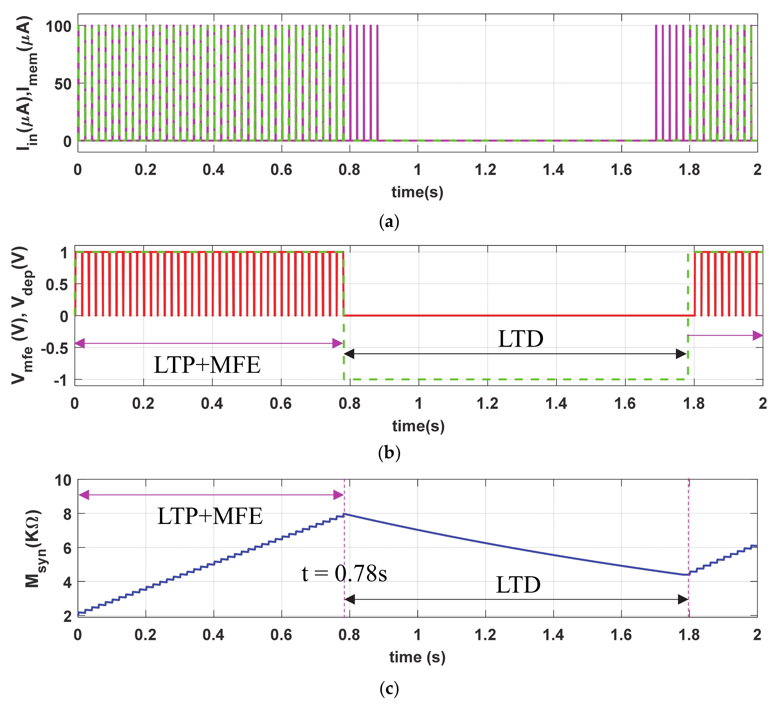
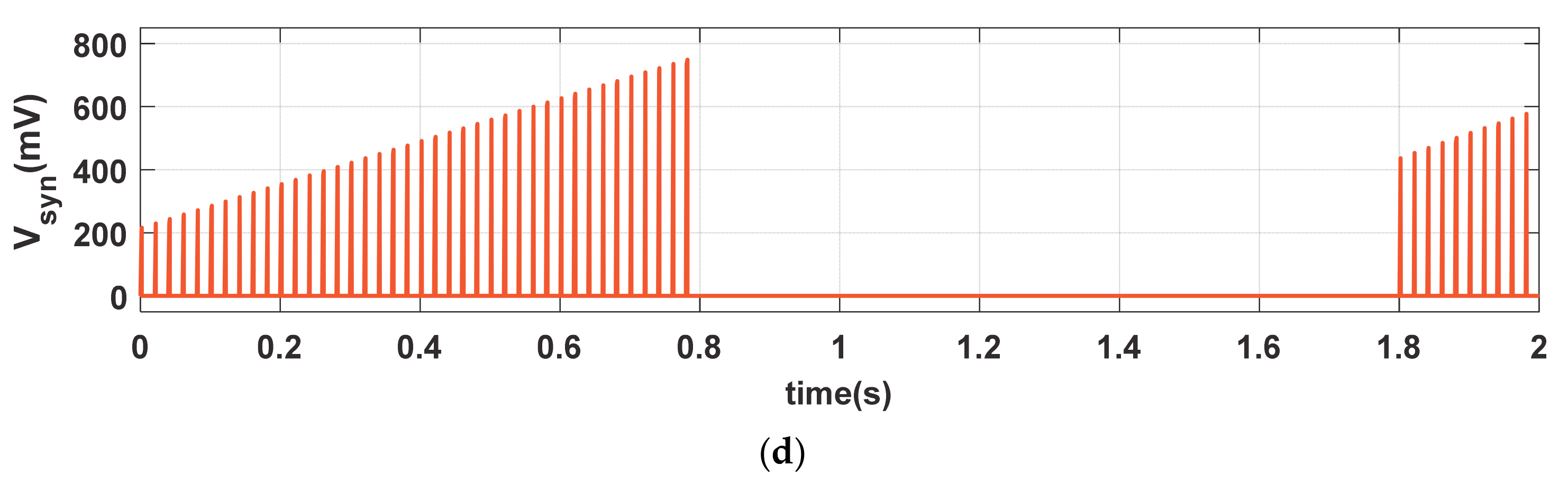
To demonstrate the long-term plasticity (LTP and LTD) phenomena, we stimulated the proposed synapse with same Iin (PA = 100 µA and PW = 1 ms), shown with magenta solid curve in Figure 4a, but with more than twice duty ratio (PP = 20 ms) than that of Figure 3a. The dotted green curve (Imem), in Figure 4b, shows the cyclic current stimulation passes through the neuro-memristive synapse which depends on the depression input (i.e., VDEP = high). Figure 4b shows the depression and MFE signals. The synaptic efficacy (Msyn), shown in Figure 4c, gradually increases with each stimulation in LTP period (t ≤ 0.78 s) despite the presence of active Vmfe. However, it monotonically decreases in the LTD period (0.78 s ≤ t ≤ 1.8 s) in spite the presence of presynaptic stimulation Iin (shown in Figure 4a). During the LTD period, the memristive synapse is unable to return to initial state M(0) = 2 KΩ because of the higher buildup in synaptic efficacy in LTP period. Hence, the proposed synapse produces higher Vsyn (shown in Figure 4d) when the presynaptic stimulations return to the active state after t ≥ 1.8 s than the initial period (t < 0.1 s).
The neuro-memristive synapse effectively impersonates the long-term plasticity phenomena as it produces a long-lasting enhancement in the synaptic efficacy both in the LTP and LTD processes (shown in Figure 4) and results in higher possibilities of postsynaptic firings with the return of input stimulations. Such long lasting synaptic enhancement can also be seen in biological synapse.
4.3. Short-Term Synaptic Plasticity
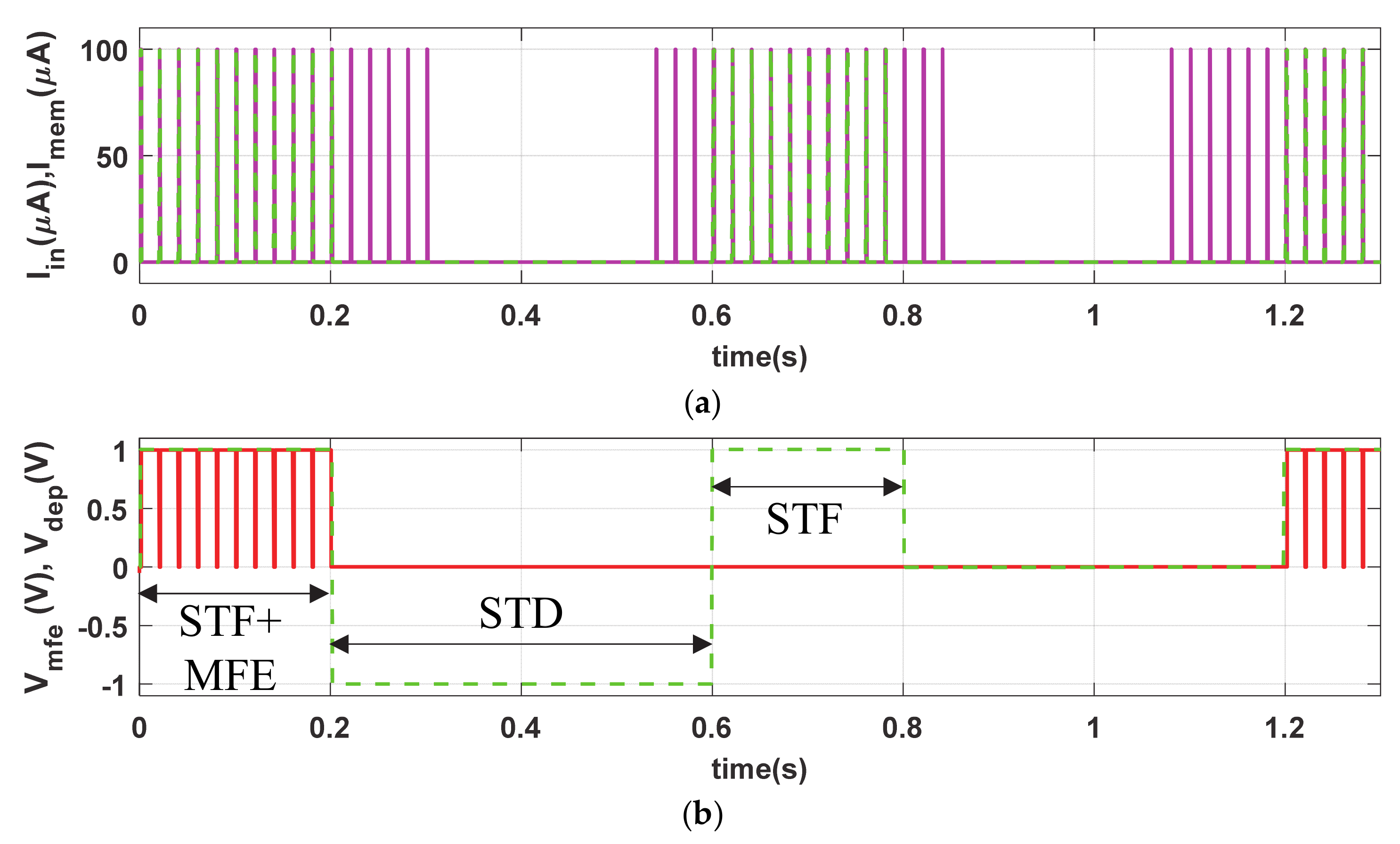
The short-term plasticity (STF and STD) phenomena of the proposed memristive synapse is demonstrated by providing a verity of diverse stimulation conditions. The input stimulus Iin (PA = 100 µA, PW = 1 ms and PP = 20 ms), shown in Figure 5a, remains the same as LTP but the stimulation time period for STF is limited to t = 0.2 s, as shown in Figure 5b. The close successive stimulus assists in gradually accumulation of synaptic efficacy, in Figure 5c, irrespective of the presence of Vmfe. In contrast, the proposed artificial synapse gradually decreases its synaptic efficacy in the active period of STD in a similar passion to that of volatile bio-synapse. However, to demonstrate the non-volatility, we provide Iin stimulations in the proposed synapse in absence of Vmfe (0.6 s ≤ t ≤ 1.2 s) as shown in Figure 5b. Observe from Figure 5c that the synaptic strength is only increased (for 0.6 s ≤ t ≤ 1.2 s) in absence of Vmfe and active presence of STF (0.6 s ≤ t ≤ 0.8 s). It holds the synaptic strength when the STF is withdrawn during 0.6 s ≤ t ≤ 0.8 s. However, the synaptic efficacy increases and decreases in presence of both STF (VDEP = High) and Vmfe at t ≥ 1.2 s and produces higher synaptic voltage (Vsyn) compared to t ≤ 0.1 s, shown in Figure 5d, due to higher buildup in Msyn.
Similar to bio-synapse, the strength of artificial neuro-memristive synapse (Msyn) increases swiftly in STF due to close successive stimulus and decreases monotonically in STD where the higher buildup in synaptic efficacy eases the postsynaptic firings.
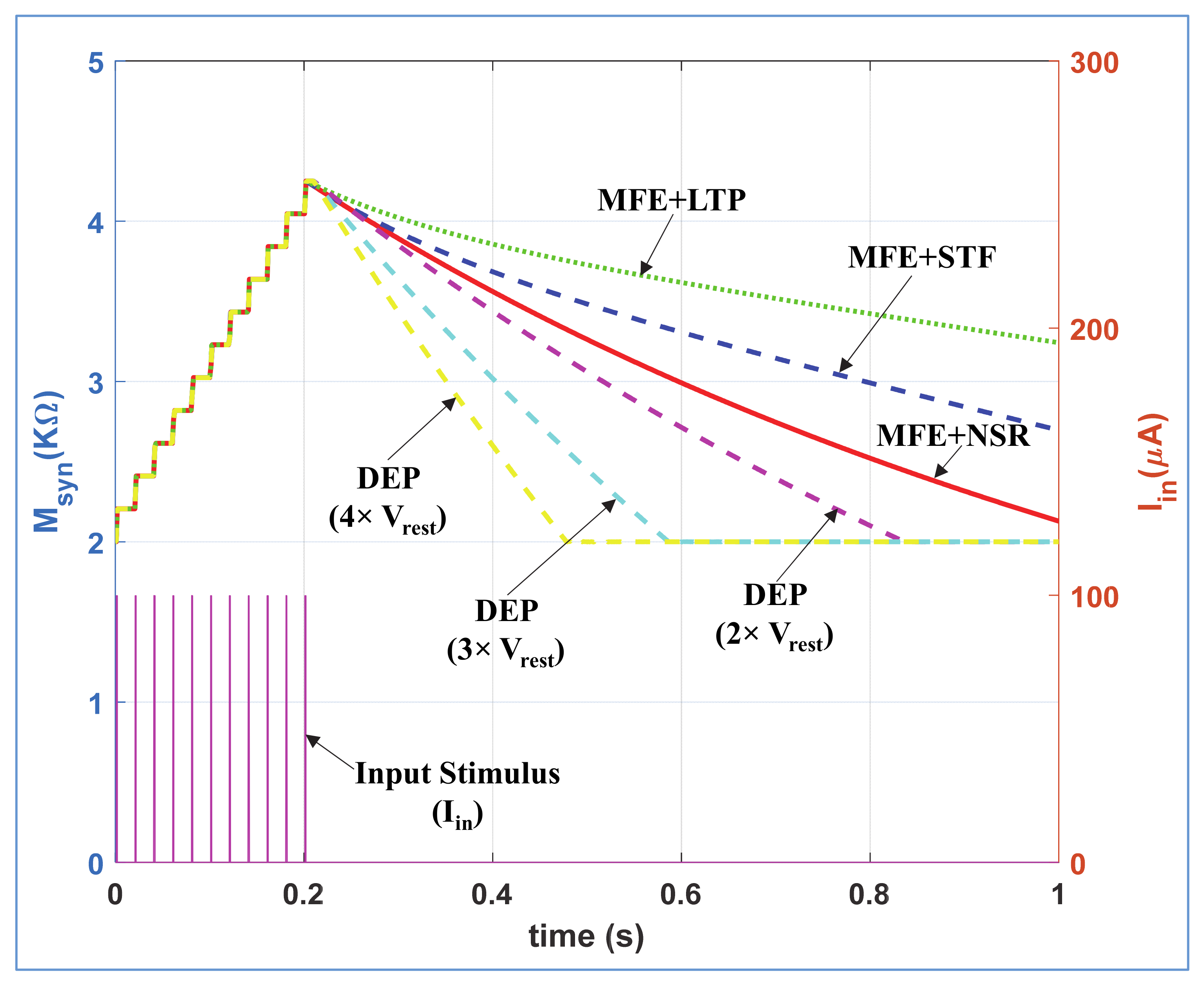
According to neuro-biology, the rate of removal of neurotransmitters from synaptic cleft (i.e., synaptic weakening) are dissimilar for depression, STF, LTP, and NSR mechanisms. To demonstrate this phenomenon, we stimulated the NSR, STF, LTP, and depression modes of the proposed neuromorphic synapse with same stimulus Iin (PA = 100 µA, PW = 1 ms and PP = 20 ms) for t ≤ 0.2 s as shown in Figure 6. In NSR, STF and LTP modes, we provide Vmfe = 0 for t ≤ 0.2 s, and Vmfe = high for t ≥ 0.2 s where VDEP = high remains same for all time. Contrarily, in depression mode, we provide VDEP = high for t ≤ 0.2 s and VDEP = low for t ≥ 0.2 s where the Vmfe = 0 remains same for all time. We provide the same VPOT signals for STF and LTP as enlisted in Table 1. Figure 6 shows that the swift artificial synaptic weakening happens in depression mode compared to NSR, STF, and LTP modes with active Vmfe. In LTP mode (with active Vmfe), the synaptic strength decreases more slowly than in STF and NSR. Moreover, with different Vref = m*Vrest (shown in Figure 2), the rate of change in synaptic efficacy is controllable for depression mode as shown with cyan and magenta dotted curves in Figure 6. We incorporate this dynamic depression option in our design as the rate of removal of neurotransmitters from synaptic cleft for depression mechanism might varied with different types of bio-synapses. The synaptic weakening response of the proposed neuro-memristive synapse is qualitatively equivalent to the attributes of biological synapse.
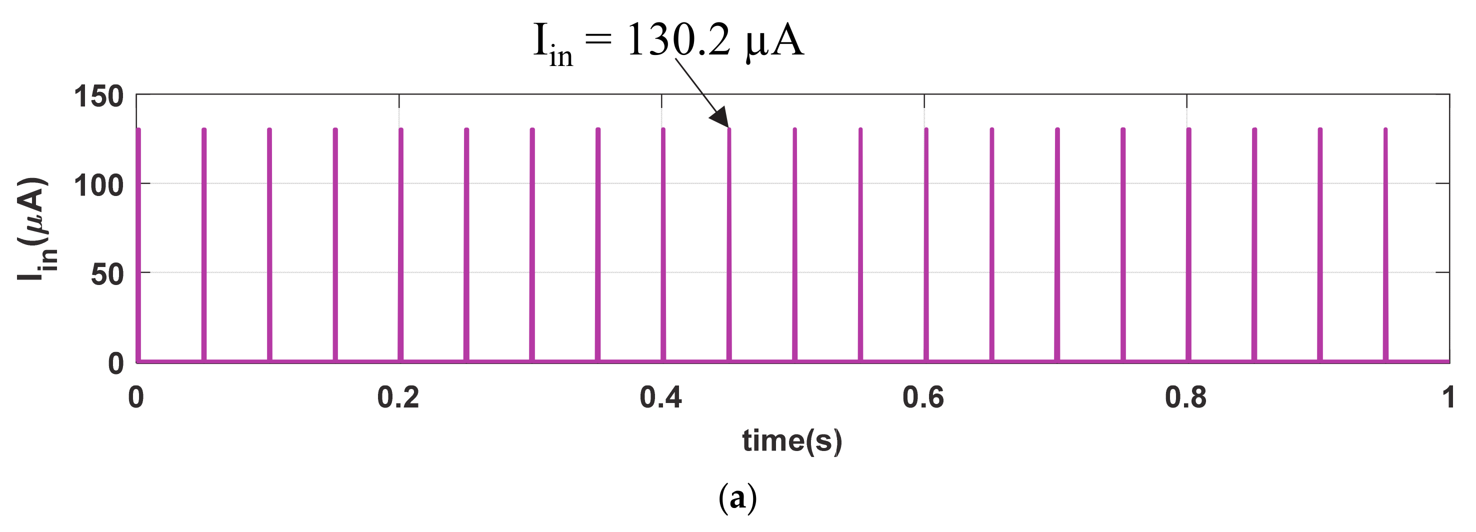
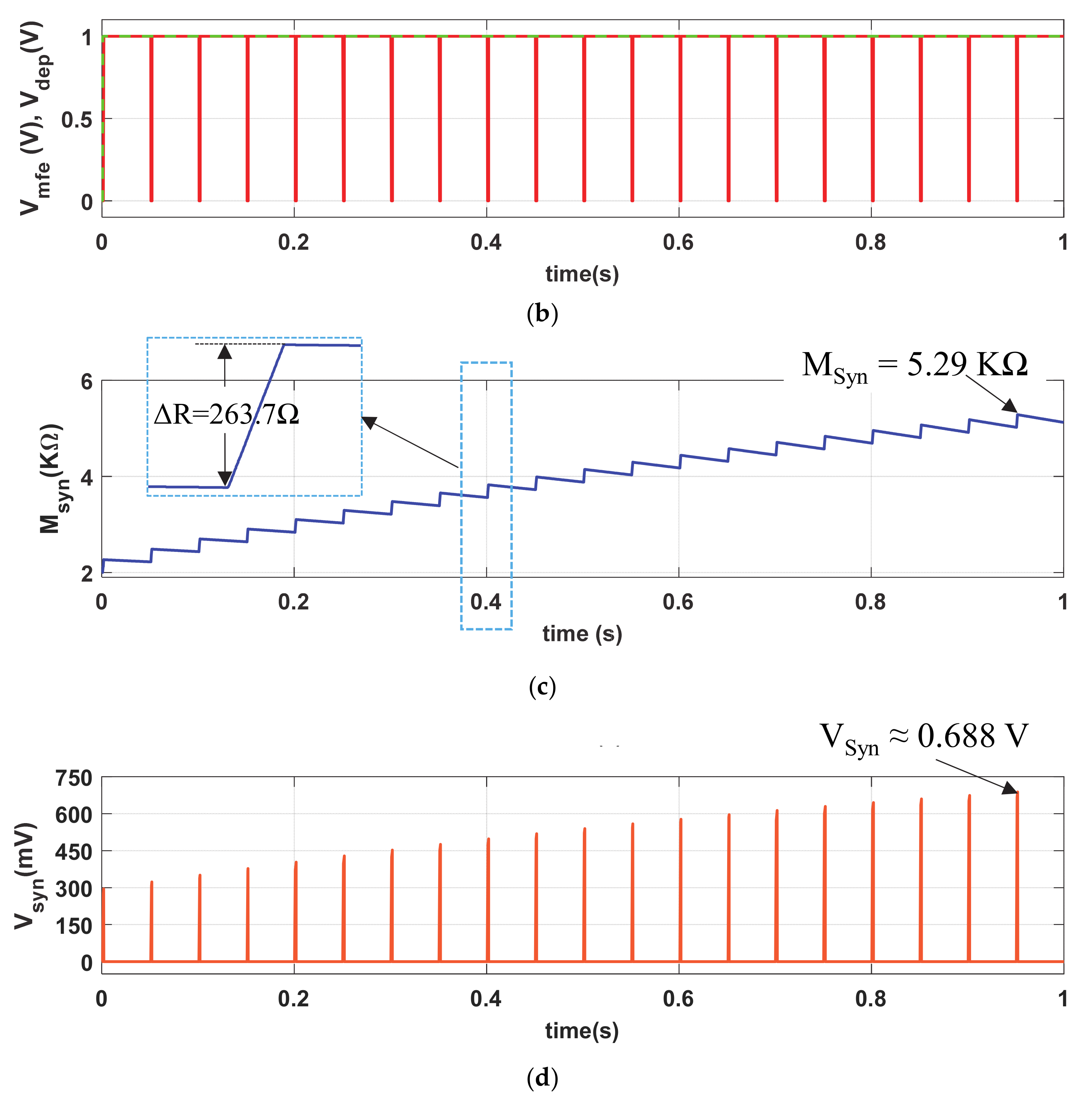
4.4. Strong Stimulation Response
We further investigate the strong stimulating phenomenon in our memristive synapse with Iin (PA = 130.2 µA, PW = 1 ms, and PP = 50 ms) as shown in Figure 7a. Observe that the stimulating inputs in Figure 3a and Figure 7a and are indifferent except the pulse amplitude (PA). Figure 7b shows the similar memory fading (Vmfe) and depression (Vdep) signals to that of Figure 3b. Due to the strong stimulus, the memristive synapse accumulates higher synaptic strength, shown in inset of Figure 7c, in each cycle of stimulation than that of Msyn in Figure 3c. Hence, the produced synaptic voltage (Vsyn), shown in Figure 7d, is also greater than that of in Figure 3d. The artificial synapse with strong-stimulation exhibits stronger enhancement in its synaptic strength than the regular stimulation and increase the possibilities of probable postsynaptic firings. Therefore, the neuro-memristive synapse effectively imitates the strong stimulation phenomenon of bio-synapse.
The above simulation results of different synaptic modes show that the proposed synaptic architecture efficiently impersonates the neuro-physiological acts of bio-synapse. Moreover, Table 3 shows the power consumption of the neuro-memristive synapse for different synaptic modes. Observe that higher power is consumed by the neuro-memristive synapse in long-term plasticity and strong stimulation modes whereas the lower power consumption occurs with short-term plasticity modes. The power consumption of the proposed memristive synapse is similar to the energy consumption of biological neuron as it requires a significant amount of power to process the information for long-term synaptic plasticity and strong stimulation.
5. Concluding Remarks
In this paper, we proposed a neuro-memristive synapse that impersonate the bio-realistic attributes of synapse and its plasticity. The impersonating features of proposed artificial synapse is verified with various SPICE simulation vis-à-vis biological phenomena. The memristive synapse explicitly exhibits the short-term (STF and STD) and long-term (LTP and LTD) plasticity phenomena. The neurotransmitter removal phenomenon through reuptake and diffusion mechanism is also exhibited with the proposed synapse. In addition, it reveals the bio-realistic behaviors, especially strong stimulation, exponentially decaying conductance trace, and voltage dependent synaptic responses, of a neuron.
Unlike multiple memory elements based prior artificial synapse, the proposed neuromorphic circuit is implemented in circuit with off-the-shelf devices and can be utilized in both volatile and nonvolatile configuration. It is not just another synaptic model based only on mathematical or macro-models of memristor. Since the conductive neuromorphic architectures overcomes the limitations of subthreshold analog- and transistor-based CMOS neural circuits and conventional Von-Neumann architectures, hence, the proposed bio-inspired synapse can be port in miniature CMOS ICs. The neuro-memristive synapse can be used to design spiking-neural networks with Hebbian or anti-Hebbian learnings. It can also be utilized in academia to analyze the synaptic functionalities of neuron instead in-vivo or in-vitro analysis and hopefully the industrial design might be used in future to design the human brain-like intelligence.
Supplementary Materials
Supplementary material is provided. The following are available online at https://0-www-mdpi-com.brum.beds.ac.uk/1424-8220/21/2/644/s1, Figure S1: Circuit diagram of the incremental memristor emulator that used to design the neuro-memristive synapse, Figure S2: (a) Relationship between memristance vs. time for the linear and nonlinear models (Joglekar’s nonlinear ionic-drift [29]) of the TiO2 memristors, (b) memristance vs. time relationship of the incremental and decremental memristor emulator, Figure S3: Frequency-dependent pinched hysteresis loops for zero-mean periodic stimulation of Iin = 100µA for (a) bi-polar sinusoidal input, and (b) pulse input with frequencies f = 10 Hz, 20 Hz, 50 Hz, 100 Hz, and 800 Hz, Figure S4: Normal synaptic response of the proposed memristive synapse for a given voltage stimulation: (a) voltage stimulation (Vin = 0.75 V), (b) memory fading effect (Vmfe) and depression (VDEP) signals, (c) current passing through the memristor emulator of neuro-memristive synapse, (d) artificial synaptic strength (Msyn), and (e) synaptic voltage (Vsyn), Figure S5: Normal synaptic response of the proposed neuro-memristive synapse with shorter pulse width: (a) current stimulus (Iin), (b) memory fading effect (Vmfe) and depression (VDEP) signals, artificial (c) synaptic strength (Msyn), and (d) synaptic voltage (Vsyn), Figure S6: Normal synaptic response of the proposed neuro-memristive synapse with lengthier pulse width: (a) current stimulus (Iin), (b) memory fading effect (Vmfe) and depression (VDEP) signals, artificial (c) synaptic strength (Msyn), and (d) synaptic voltage (Vsyn), Table S1. Equations of hp TiO2 Memristor and Memristor Emulator.
Author Contributions
Conceptualization, Z.I.M., H.K. and L.C.; methodology, Z.I.M.; software, Z.I.M.; validation, Z.I.M., H.K. and L.C.; formal analysis, Z.I.M., H.K. and L.C.; investigation, Z.I.M., H.K. and L.C.; resources, H.K. and L.C.; data curation, Z.I.M., H.K. and L.C.; writing—original draft preparation, Z.I.M.; writing—review and editing, Z.I.M., H.K. and L.C.; visualization, Z.I.M.; supervision, H.K. and L.C.; project administration, H.K. and L.C.; funding acquisition, H.K. All authors have read and agreed to the published version of the manuscript.
Funding
This work was supported in part by the Basic Science Research Program through the National Research Foundation of Korea (NRF) funded by the Ministry of Education (NRF-2019R1A6A1A09031717 and NRF-2019R1A2C1011297), and the US Air Force Office of Scientific Research under Grant number FA9550-18-1-0016.
Institutional Review Board Statement
“Not applicable” for this study as humans or animals are not involved.
Informed Consent Statement
“Not applicable” for this study as humans are not involved.
Data Availability Statement
No Data available online. For further query email to corresponding author ([email protected]).
Conflicts of Interest
There is no conflict of interest.
References
- Woo, J.; Moon, K.; Song, J.; Lee, S.; Kwak, M.; Park, J.; Hwang, H. Improved synaptic behavior under identical pulses using AlOx/HfO2 bilayer RRAM array for neuromorphic systems. IEEE Electron Device Lett. 2016, 37, 994–997. [Google Scholar] [CrossRef]
- Schwartz, A.B.; Cui, X.T.; Weber, D.J.; Moran, D.W. Brain-Controlled Interfaces: Movement restoration with neural prosthetics. Neuron 2006, 52, 205–220. [Google Scholar] [CrossRef] [Green Version]
- Orsborn, A.L.; Carmena, J.M. Creating new functional circuits for action via brain-machine interfaces. Front. Comput. Neurosci. 2013, 7, 1–10. [Google Scholar] [CrossRef] [PubMed] [Green Version]
- Indiveri, G.; Chicca, E.; Douglas, R. A VLSI array of low-power spiking neurons and bistable synapses with spike-timing dependent plasticity. IEEE Trans. Neural Netw. 2006, 17, 211–221. [Google Scholar] [CrossRef] [PubMed] [Green Version]
- Zhang, J.; Wang, Y.; Zhang, X.; Huang, R. Compact digital-controlled neuromorphic circuit with low power consumption. In Proceedings of the IEEE International Symposium on Circuits and Systems (ISCAS), Baltimore, MD, USA, 28–31 May 2017. [Google Scholar]
- Rachmuth, G.; Shouval, H.Z.; Bear, M.F.; Poon, C.S. A biophysically-based neuromorphic model of spike rate- and timing-dependent plasticity. Proc. Natl. Acad. Sci. USA 2011, 108, 1266–1274. [Google Scholar] [CrossRef] [PubMed] [Green Version]
- Werner, T.; Vianello, E.; Bichler, O.; Grossi, A.; Nowak, E.; Nodin, J.F.; Yvert, B.; Salvo, B.D.; Perniola, L. Experimental demonstration of short and long term synaptic plasticity using OxRAM multi k-bit arrays for reliable detection in highly noisy input data. In Proceedings of the IEEE International Electron Devices Meeting (IEDM), San Francisco, CA, USA, 3–7 December 2016. [Google Scholar]
- Noack, M.; Krause, M.; Mayr, C.; Partzsch, J.; Schüffny, R. VLSI implementation of a conductance-based multi-synapse using switched-capacitor circuits. In Proceedings of the IEEE International Symposium on Circuits and Systems (ISCAS), Melbourne, Australia, 1–5 June 2014. [Google Scholar]
- Sengupta, A.; Banerjee, A.; Roy, K. Hybrid spintronic-CMOS spiking neural network with on-chip learning: Devices, circuits, and systems. Phys. Rev. Appl. 2016, 6, 1–13. [Google Scholar] [CrossRef] [Green Version]
- Kim, H.; Sah, M.P.; Yang, C.; Roska, T.; Chua, L.O. Memristor bridge synapses. Proc. IEEE 2012, 100, 2061–2070. [Google Scholar] [CrossRef]
- Chua, L. Memristor, Hodgkin-Huxley, and edge of chaos. Nanotechnology 2013, 24, 1–14. [Google Scholar] [CrossRef]
- Li, Q.; Serb, A.; Prodromakis, T.; Xu, H. A memristor SPICE model accounting for synaptic activity dependence. PLoS ONE 2015, 10, e0120506. [Google Scholar] [CrossRef] [Green Version]
- Azghadi, M.R.; Barranco, B.L.; Abbott, D.; Leong, P.H.W. A hybrid CMOS-memristor neuromorphic synapse. IEEE Trans. Biomed. Circuits Syst. 2017, 11, 434–445. [Google Scholar] [CrossRef] [Green Version]
- Mannan, Z.I.; Adhikari, S.P.; Yang, C.; Budhathoki, R.K.; Kim, H.; Chua, L. Memristive imitation of synaptic transmission and plasticity. IEEE Trans. Neural Netw. Learn. Syst. 2019, 30, 3458–3470. [Google Scholar] [CrossRef] [PubMed]
- Wang, Z.; Rao, M.; Han, J.W.; Zhang, J.; Lin, P.; Li, Y.; Li, C.; Song, W.; Asapu, S.; Midya, R.; et al. Capacitive neural network with neuro-transistors. Nat. Commun. 2018, 9, 1–10. [Google Scholar] [CrossRef] [PubMed]
- Liu, C.; Yang, Q.; Zhang, C.; Jiang, H.; Wu, Q.; Li, H. A memristor-based neuromorphic engine with a current sensing scheme for artificial neural network applications. In Proceedings of the IEEE 22nd Asia and South Pacific Design Automation Conference (ASP-DAC), Chiba, Japan, 16–19 January 2017. [Google Scholar]
- Suszkiw, J.B. Synaptic transmission. In Cell Physiology Source Book, 4th ed.; Elsevier Academic Press: Burlington, MA, USA, 2012; Chapter 32. [Google Scholar]
- Hille, B. Ion Channels of Excitable Membranes, 3rd ed.; Sinauer Associates Inc.: Sunderland, MA, USA, 2001. [Google Scholar]
- Purves, D. Neuroscience, 3rd ed.; Sinauer Associates Inc.: Sunderland, MA, USA, 2011. [Google Scholar]
- Campbell, N.A.; Reece, J.B. Biology, 9th ed.; Pearson: San Francisco, CA, USA, 2010. [Google Scholar]
- Becker, W.M.; Kleinsmith, L.J.; Hardin, J.; Bertoni, G.P. The World of the Cell, 7th ed.; Pearson/Benjamin Cumming: San Francisco, CA, USA, 2009. [Google Scholar]
- Wang, J.-H.; Wei, J.; Chen, X.; Yu, J.; Chen, N.; Shi, J. Gain and fidelity of transmission patterns at cortical excitatory unitary synapses improve spike encoding. J. Cell Sci. 2008, 121, 2951–2960. [Google Scholar] [CrossRef] [PubMed] [Green Version]
- Yu, J.; Qian, H.; Chen, N.; Wang, J.H. Quantal glutamate release is essential for reliable neuronal encodings in cerebral networks. PLoS ONE 2011, 6, e25219-1–10. [Google Scholar] [CrossRef] [PubMed]
- Timberlake, K.C. General, Organic, and Biological Chemistry: Structures of Life, 6th ed.Pearson Education Inc: San Francisco, CA, USA, 2019. [Google Scholar]
- Fortune, E.S.; Rose, G.J. Short-term synaptic plasticity as a temporal filter. Trends Neurosci. 2001, 24, 381–385. [Google Scholar] [CrossRef]
- Cooke, S.F.; Bliss, T.V.P. Plasticity in the human central nervous system. Brain 2006, 129, 1659–1673. [Google Scholar] [CrossRef] [Green Version]
- Escobar, M.L.; Derrick, B. Neural Plasticity and Memory: From Genes to Brain Imaging; Chapter 2; CRC Press: Boca Raton, FL, USA, 2007. [Google Scholar]
- Kim, H.; Sah, M.P.; Yang, C.; Cho, S.; Chua, L.O. Memristor emulator for memristor circuit applications. IEEE Trans. Circuit Syst. I Regul. Pap. 2012, 59, 2422–2431. [Google Scholar]
- Joglekar, Y.N.; Wolf, S.J. The elusive memristor: Properties of basic electrical circuits. Eur. J. Phys. 2009, 30, 661–675. [Google Scholar] [CrossRef] [Green Version]
- Prodromakis, T.; Peh, B.P.; Papavassiliou, C.; Toumazou, C. A versatile memristor model with nonlinear dopant kinetics. IEEE Trans. Elect. Devices 2011, 58, 3099–3105. [Google Scholar] [CrossRef]
- Kim, H.; Sah, M.P.; Yang, C.; Rosak, T.; Chua, L.O. Neural synaptic weighting with a pulse-based memristor circuit. IEEE Trans. Circuits Syst. I 2012, 59, 148–158. [Google Scholar] [CrossRef]
- Prezioso, M.; Bayat, F.M.; Hoskins, B.D.; Adam, G.C.; Likharev, K.K.; Strukov, D.B. Training and operation of an integrated neuromorphic network based on metal-oxide memristors. Nature 2015, 521, 61–64. [Google Scholar] [CrossRef] [PubMed] [Green Version]
- Li, C.; Belkin, D.; Li, Y.; Yan, P.; Hu, M.; Ge, N.; Jiang, H.; Montgomery, E.; Lin, P.; Wang, Z.; et al. Efficient and self-adaptive in-situ learning in multilayer memristor neural networks. Nat. Commun. 2018, 9, 2385. [Google Scholar] [CrossRef] [PubMed] [Green Version]
Figure 1.
(a) Diagram of neuron–neuron communication in a neuronal network, (b) steps of bio-synaptic transmission, and (c) neurotransmitters reuptake process.
Figure 1.
(a) Diagram of neuron–neuron communication in a neuronal network, (b) steps of bio-synaptic transmission, and (c) neurotransmitters reuptake process.

Figure 2.
Proposed neuro-memristive synapse.

Figure 3.
Normal synaptic response (NSR) of the proposed memristive synapse: (a) current stimulus (Iin), (b) memory fading effect (Vmfe) and depression (VDEP) signals, artificial (c) synaptic strength (Msyn), and (d) synaptic voltage (Vsyn).
Figure 3.
Normal synaptic response (NSR) of the proposed memristive synapse: (a) current stimulus (Iin), (b) memory fading effect (Vmfe) and depression (VDEP) signals, artificial (c) synaptic strength (Msyn), and (d) synaptic voltage (Vsyn).

Figure 4.
Long-term potentiation (LTP) and long-term depression (LTD) synaptic response of neuro-memristive synapse: (a) input stimulus (Iin) and current stimulus passes through proposed synapse (Imem), (b) control signals of Vmfe and VDEP, artificial synaptic (c) strength (Msyn), and (d) voltage (Vsyn).


Figure 5.
Volatile short-term facilitation (STF) and short-term depression STD, and nonvolatile synaptic responses of the proposed circuit. (a) Input stimulus (Iin) and current stimulus passes through proposed synapse (Imem), (b) Vmfe and VDEP signals, artificial synaptic (c) efficacy (Msyn), and (d) voltage (Vsyn).


Figure 6.
Comparison of synaptic weakening (Msyn) between the different modes of proposed neuro-memristive synapse.
Figure 6.
Comparison of synaptic weakening (Msyn) between the different modes of proposed neuro-memristive synapse.

Figure 7.
Strong stimulation response of neuro-memristive synapse. (a) Strong stimulus (Iin), (b) Vmfe and VDEP signals, artificial (c) synaptic strength (Msyn), and (d) synaptic voltage (Vsyn).
Figure 7.
Strong stimulation response of neuro-memristive synapse. (a) Strong stimulus (Iin), (b) Vmfe and VDEP signals, artificial (c) synaptic strength (Msyn), and (d) synaptic voltage (Vsyn).


Table 1.
Modes of operation of the proposed neuro-memristive synapse.
| Memory Type | Synaptic Mode | Synaptic Response | Operating Signals | ||
|---|---|---|---|---|---|
| VDEP | VMFE | VPOT | |||
| Volatile | Potentiation | NSR + MFE | VH | VH | 0 |
| STF + MFE | VH | VH | VL | ||
| LTP + MFE | VH | VH | VH | ||
| Depression | STD | VL | VL | VH/VL | |
| LTD | VH | VH | VH/VL | ||
| Nonvolatile | Potentiation | NSR | VH | VL | 0 |
| STF | VH | VL | 0 | ||
| LTP | VH | VL | 0 | ||
Table 2.
Circuit parameters of the neuro-memristive synapse that used in experiments.
| Parameters | Value | Parameters | Value |
|---|---|---|---|
| VDD/VH | 3 V | VDA | −Vin |
| VSS/VL | −3 V | CCon | 15 µF |
| Vrest | −90 mV | RST | 2 KΩ |
| Vref | 4 × Vrest | RLT | 1 KΩ |
| VPOT | 0/VH/VL | RL | 10 KΩ |
Table 3.
Power consumption of different synaptic modes of the neuro-memristive synapse.
| Synaptic Modes | Power Consumptions (µW) |
|---|---|
| Normal Synaptic Response (NSR) | 196.553 |
| Short-term Plasticity volatile region (STF + STD) | 131.994 |
| Short-term Plasticity Nonvolatile region (STF) | 156.83 |
| Long-term Plasticity | 452.95 |
| Strong Stimulation | 424.921 |
Publisher’s Note: MDPI stays neutral with regard to jurisdictional claims in published maps and institutional affiliations. |
© 2021 by the authors. Licensee MDPI, Basel, Switzerland. This article is an open access article distributed under the terms and conditions of the Creative Commons Attribution (CC BY) license (http://creativecommons.org/licenses/by/4.0/).
Share and Cite
MDPI and ACS Style
Mannan, Z.I.; Kim, H.; Chua, L. Implementation of Neuro-Memristive Synapse for Long-and Short-Term Bio-Synaptic Plasticity. Sensors 2021, 21, 644. https://0-doi-org.brum.beds.ac.uk/10.3390/s21020644
AMA Style
Mannan ZI, Kim H, Chua L. Implementation of Neuro-Memristive Synapse for Long-and Short-Term Bio-Synaptic Plasticity. Sensors. 2021; 21(2):644. https://0-doi-org.brum.beds.ac.uk/10.3390/s21020644
Chicago/Turabian StyleMannan, Zubaer I., Hyongsuk Kim, and Leon Chua. 2021. "Implementation of Neuro-Memristive Synapse for Long-and Short-Term Bio-Synaptic Plasticity" Sensors 21, no. 2: 644. https://0-doi-org.brum.beds.ac.uk/10.3390/s21020644
Note that from the first issue of 2016, this journal uses article numbers instead of page numbers. See further details here.