
Comparative Study of γ- and e-Radiation-Induced Effects on FBGs Using Different Femtosecond Laser Inscription Methods

 , , , , ,
  , , and
Abstract
:1. Introduction
2. Materials and Methods
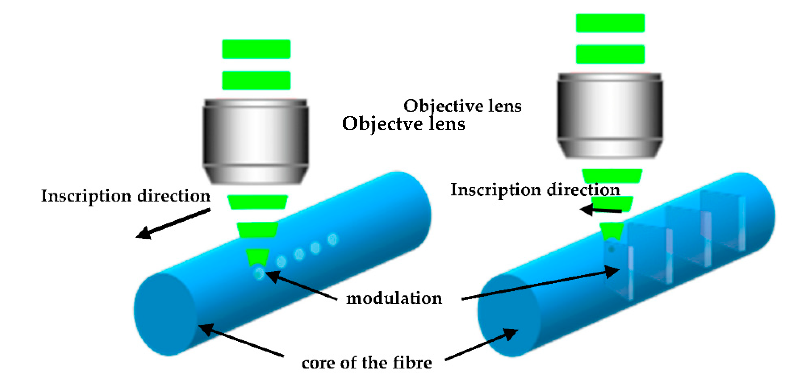
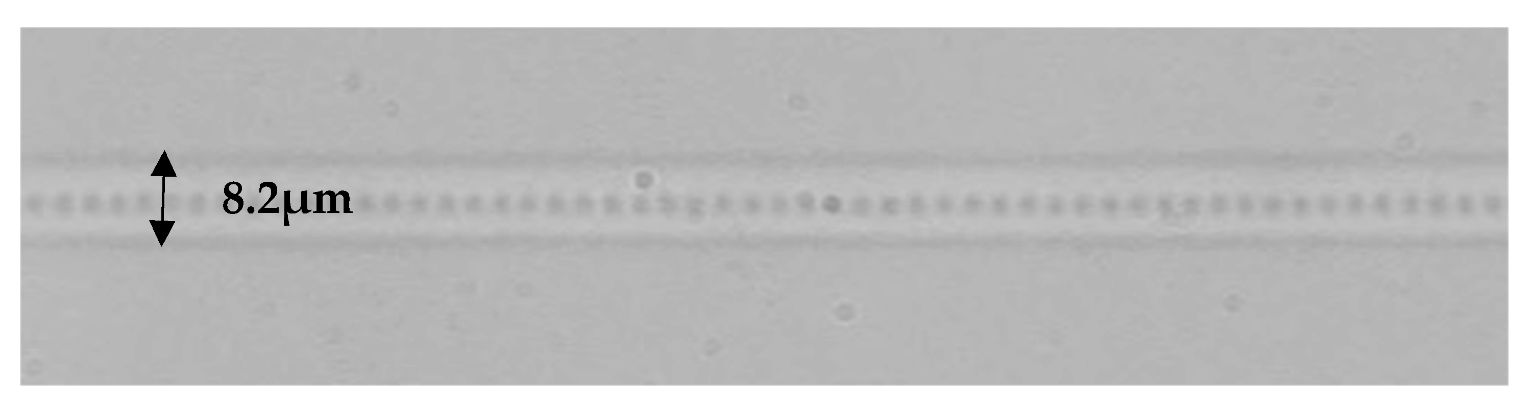
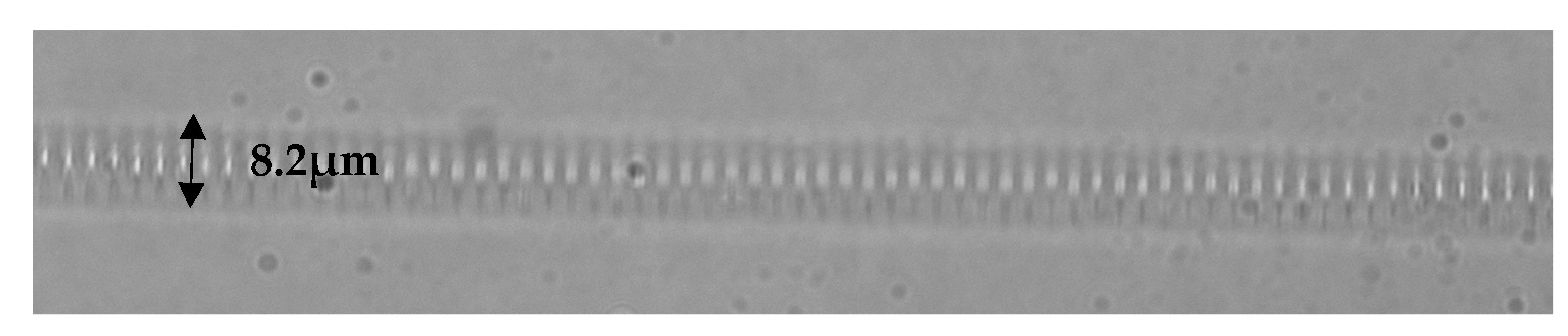
2.1. Inscription Details
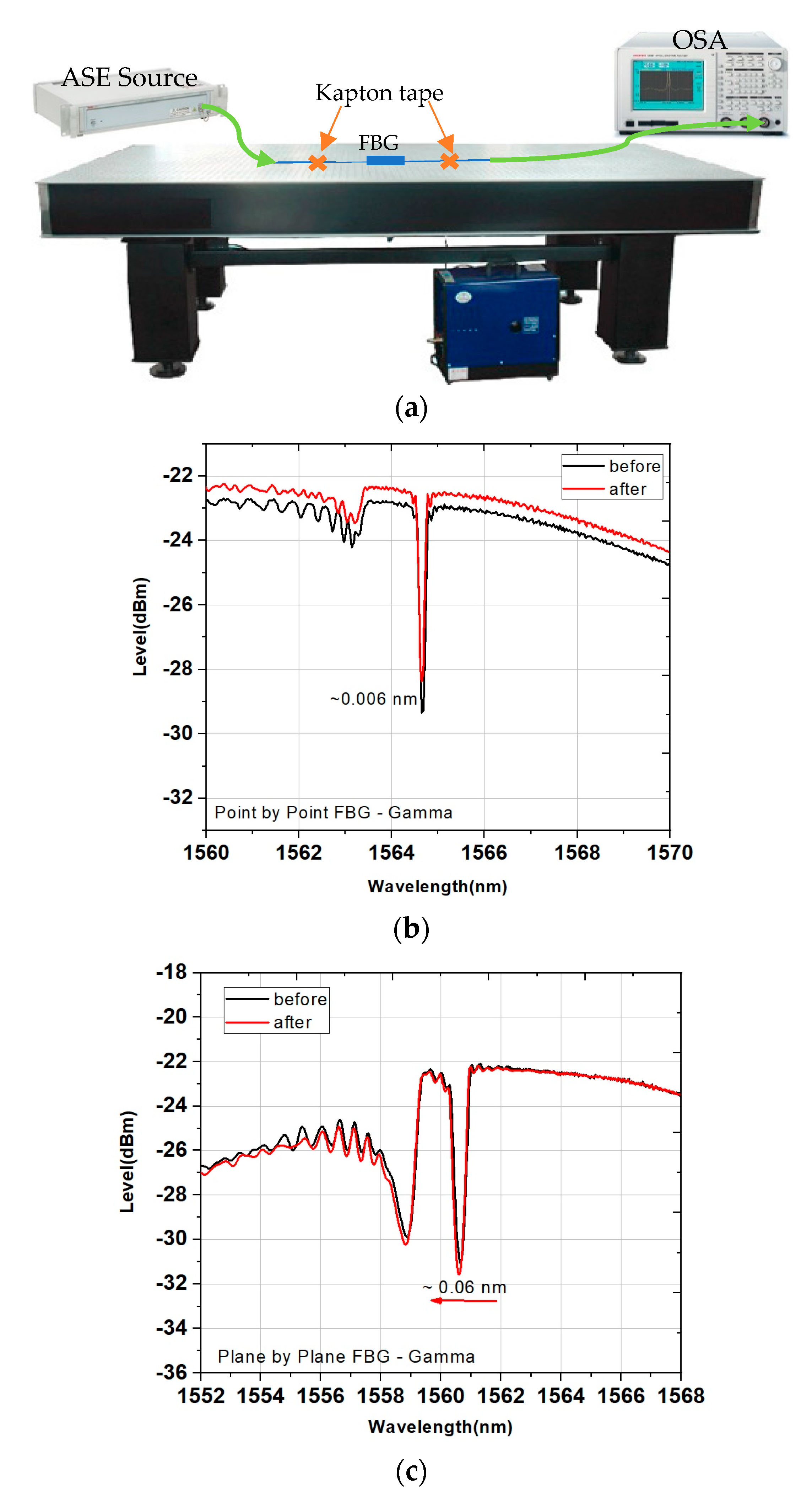
2.2. Radiation Exposure Details
3. Results
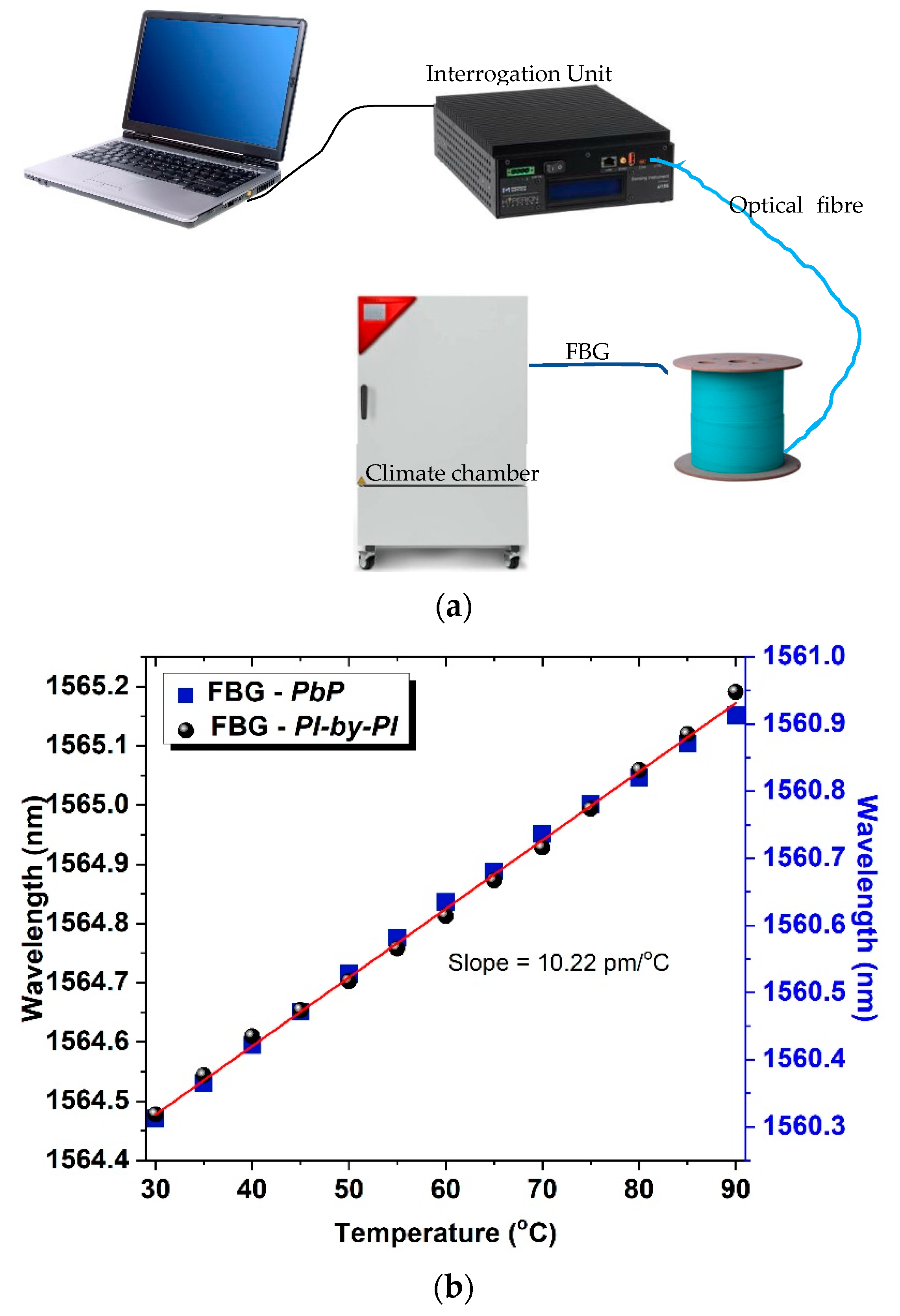
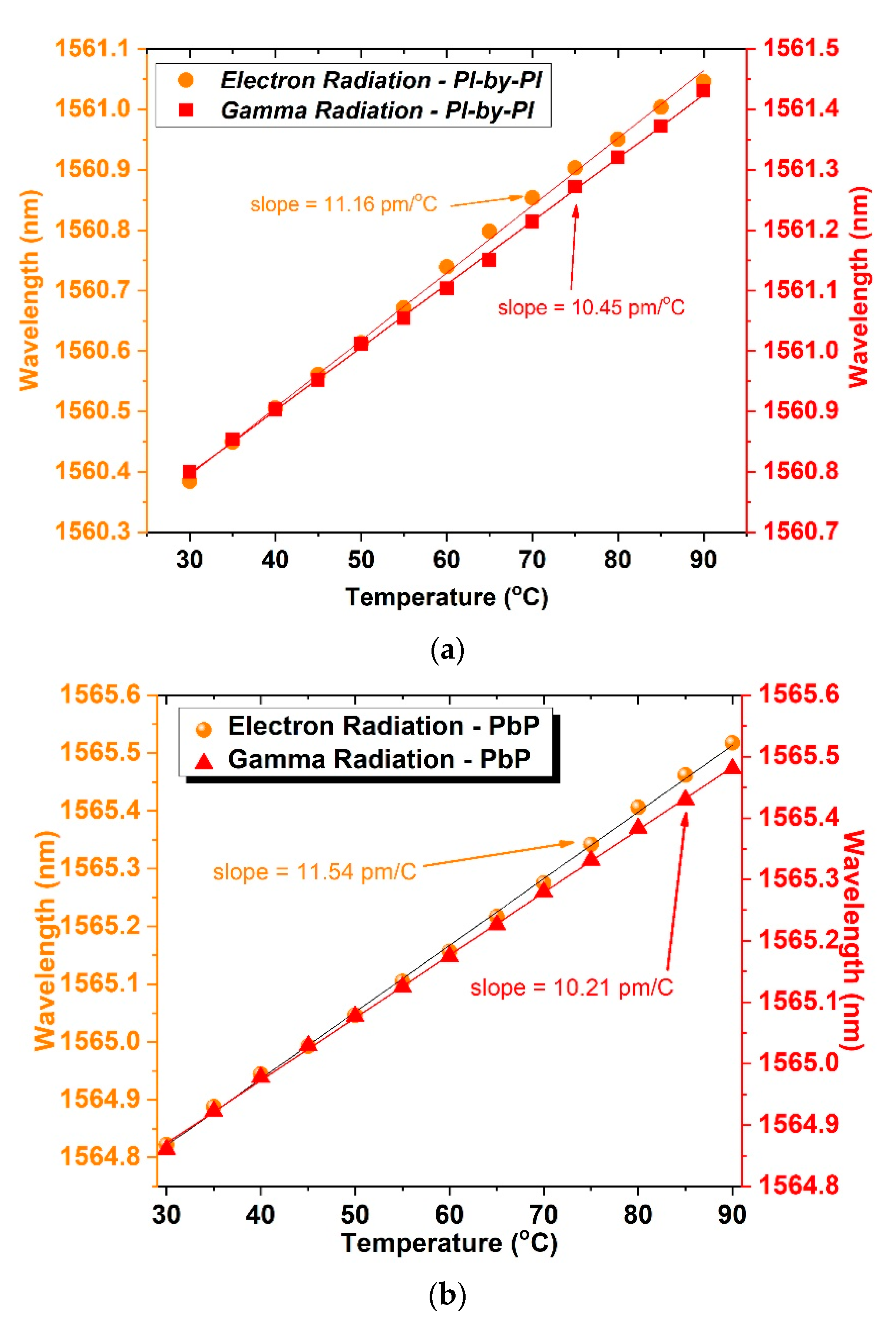
3.1. Thermal Response
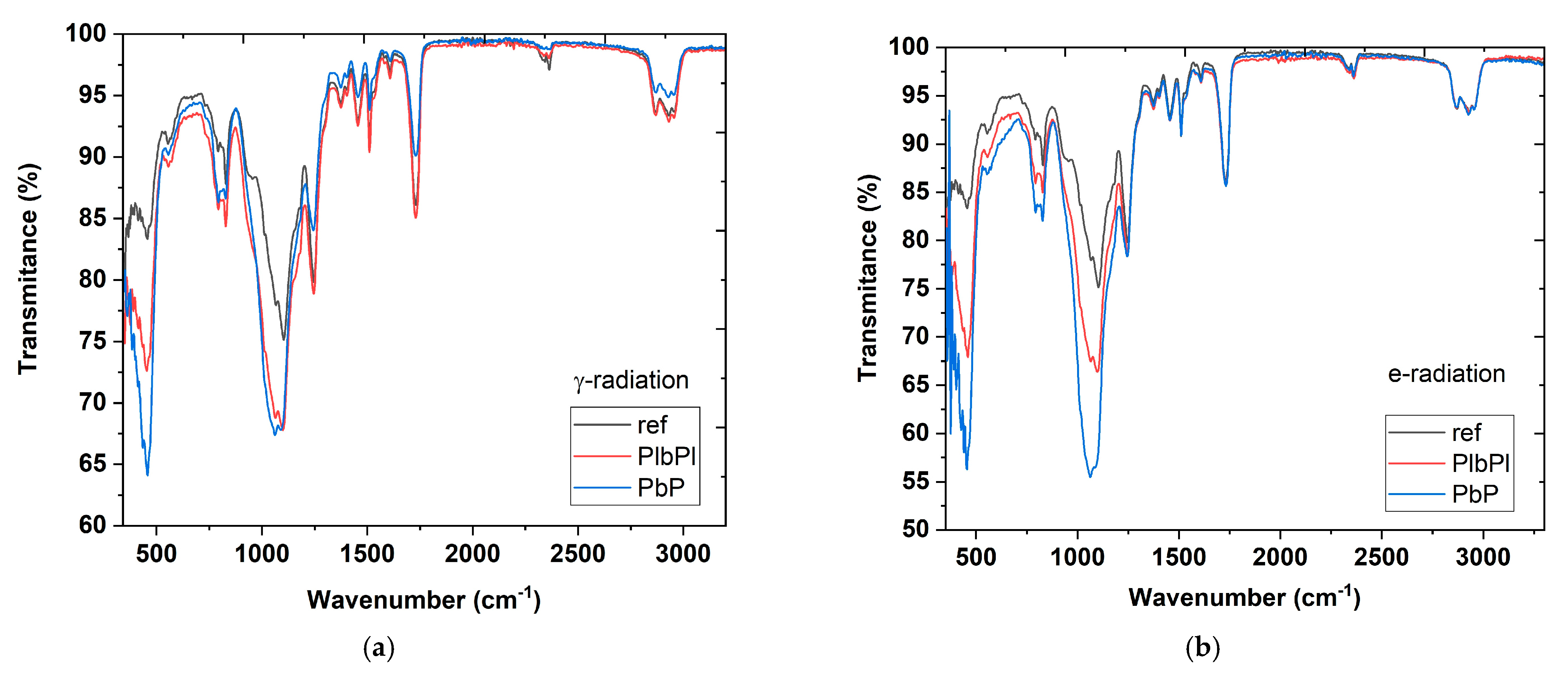
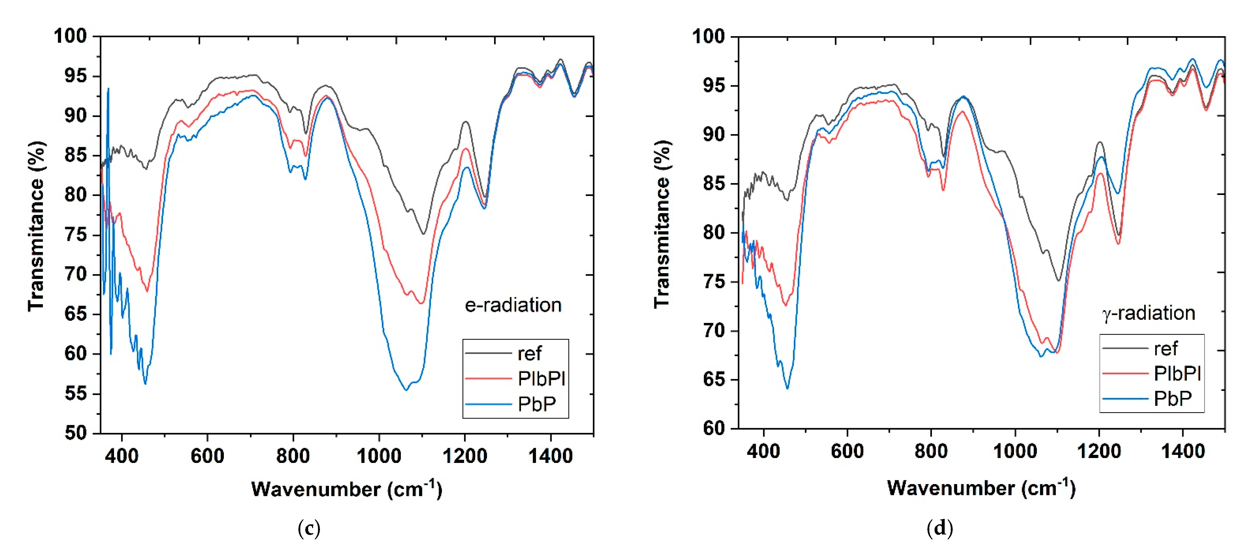
3.2. FTIR Measurements
4. Discussion
5. Conclusions
Author Contributions
Funding
Institutional Review Board Statement
Informed Consent Statement
Conflicts of Interest
References
- Othonos, A. Fiber Bragg gratings. Rev. Sci. Instrum. 1997, 68, 4309–4341. [Google Scholar] [CrossRef]
- Othonos, A.; Kalli, K. Fiber Bragg Gratings: Fundamentals and Applications in Telecommunications and Sensing, 1st ed.; Artech House: Norwood, MA, USA, 1999. [Google Scholar]
- Girard, S.; Kuhnhenn, J.; Gusarov, A.; Brichard, B.; Van Uffelen, M.; Ouerdane, Y.; Boukenter, A.; Marcandella, C. Radiation Effects on Silica-Based Optical Fibers: Recent Advances and Future Challenges. IEEE Trans. Nucl. Sci. 2013, 60, 2015–2036. [Google Scholar] [CrossRef]
- Girard, S.; Ouerdane, Y.; Tortech, B.; Marcandella, C.; Robin, T.; Cadier, B.; Baggio, J.; Paillet, P.; Ferlet-Cavrois, V.; Boukenter, A.; et al. Radiation Effects on Ytterbium- and Ytterbium/Erbium-Doped Double-Clad Optical Fibers. IEEE Trans. Nucl. Sci. 2009, 56, 3293–3299. [Google Scholar] [CrossRef]
- Henschel, H.; Kohn, O.; Schmidt, H.U.; Kirchof, J.; Unger, S. Radiation-induced loss of rare earth doped silica fibres. IEEE Trans. Nucl. Sci. 1998, 45, 1552–1557. [Google Scholar] [CrossRef]
- Faustov, A.; Saffari, P.; Koutsides, C.; Gusarov, A.; Wuilpart, M.; Megret, P.; Kalli, K.; Zhang, L. Highly Radiation Sensitive Type IA FBGs for Future Dosimetry Applications. IEEE Trans. Nucl. Sci. 2012, 59, 1180–1185. [Google Scholar] [CrossRef]
- Kalli, K.; Simpson, A.G.; Zhou, K.; Zhang, L.; Bennion, I. Tailoring the temperature and strain coefficients of Type I and Type IA dual grating sensors—The impact of hydrogenation conditions. Meas. Sci. Technol. 2006, 17, 949–954. [Google Scholar] [CrossRef]
- De Michele, V.; Marcandella, C.; Vidalot, J.; Paillet, P.; Morana, A.; Cannas, M.; Boukenter, A.; Marin, E.; Ouerdane, Y.; Girard, S. Origins of radiation-induced attenuation in pure-silica-core and Ge-doped optical fibers under pulsed x-ray irradiation. J. Appl. Phys. 2020, 128, 103101. [Google Scholar] [CrossRef]
- Gusarov, A.; Brichard, B.; Nikogosyan, D.N. Gamma-Radiation Effects on Bragg Gratings Written by Femtosecond UV Laser in Ge-Doped Fibers. IEEE Trans. Nucl. Sci. 2010, 57, 2024–2028. [Google Scholar] [CrossRef]
- Mihailov, S.; Grobnic, D.; Hnatovsky, C.; Walker, R.; Lu, P.; Coulas, D.; Ding, H. Extreme Environment Sensing Using Femtosecond Laser-Inscribed Fiber Bragg Gratings. Sensors 2017, 17, 2909. [Google Scholar] [CrossRef] [PubMed] [Green Version]
- Brichard, B.; Butov, O.V.; Golant, K.M.; Fernandez Fernandez, A. Gamma radiation-induced refractive index change in Ge- and N-doped silica. J. Appl. Phys. 2008, 103, 054905. [Google Scholar] [CrossRef] [Green Version]
- Di Francesca, D.; Brugger, M.; Vecchi, G.L.; Girard, S.; Morana, A.; Reghioua, I.; Alessi, A.; Hoehr, C.; Robin, T.; Kadi, Y. Qualification and Calibration of Single-Mode Phosphosilicate Optical Fiber for Dosimetry at CERN. J. Light. Technol. 2019, 37, 4643–4649. [Google Scholar] [CrossRef]
- Olivero, M.; Mirigaldi, A.; Serafini, V.; Vallan, A.; Perrone, G.; Blanc, W.; Benabdesselam, M.; Mady, F.; Molardi, C.; Tosi, D. Distributed X-ray Dosimetry with Optical Fibers by Optical Frequency Domain Interferometry. IEEE Trans. Instrum. Meas. 2021, 70, 1–9. [Google Scholar] [CrossRef]
- Thomas, S.; Fusco, T.; Tokovinin, A.; Nicolle, M.; Michau, V.; Rousset, G. Comparison of centroid computation algorithms in a Shack–Hartmann sensor. Mon. Not. R. Astron. Soc. 2006, 336, 323–336. [Google Scholar] [CrossRef] [Green Version]
- Pospori, A.; Marques, C.A.F.; Sagias, G.; Lamela-Rivera, H.; Webb, D.J. Novel thermal annealing methodology for permanent tuning polymer optical fiber Bragg gratings to longer wavelengths. Opt. Express 2018, 26, 1411. [Google Scholar] [CrossRef]
- Marshall, G.D.; Williams, R.J.; Jovanovic, N.; Steel, M.J.; Withford, M.J. Point-by-point written fiber-Bragg gratings and their application in complex grating designs. Opt. Express 2010, 18, 19844. [Google Scholar] [CrossRef] [PubMed]
- Malo, B.; Hill, K.O.; Bilodeau, F.; Johnson, D.C.; Albert, J. Point-by-point fabrication of micro-Bragg gratings in photosensitive fibre using single excimer pulse refractive index modification techniques. Electron. Lett. 1993, 29, 1668. [Google Scholar] [CrossRef]
- Geernaert, T.; Kalli, K.; Koutsides, C.; Komodromos, M.; Nasilowski, T.; Urbanczyk, W.; Wojcik, J.; Berghmans, F.; Thienpont, H. Point-by-point fiber Bragg grating inscription in free-standing step-index and photonic crystal fibers using near-IR femtosecond laser. Opt. Lett. 2010, 35, 1647. [Google Scholar] [CrossRef] [PubMed]
- Huang, B.; Shu, X. Ultra-compact strain- and temperature-insensitive torsion sensor based on a line-by-line inscribed phase-shifted FBG. Opt. Express 2016, 24, 17670. [Google Scholar] [CrossRef]
- Fuerbach, A.; Bharathan, G.; Antipov, S.; Ams, M.; Williams, R.J.; Hudson, D.D.; Woodward, R.I.; Jackson, S.D. Line-by-line Femtosecond FBG Inscription for Innovative Fiber Lasers. In Advanced Photonics 2018 (BGPP, IPR, NP, NOMA, Sensors, Networks, SPPCom, SOF); OSA: Washington, DC, USA, 2018; p. BW3A.6. [Google Scholar]
- Theodosiou, A.; Lacraz, A.; Polis, M.; Kalli, K.; Tsangari, M.; Stassis, A.; Komodromos, M. Modified fs-Laser Inscribed FBG Array for Rapid Mode Shape Capture of Free-Free Vibrating Beams. IEEE Photonics Technol. Lett. 2016, 28, 1509–1512. [Google Scholar] [CrossRef]
- Theodosiou, A.; Lacraz, A.; Stassis, A.; Koutsides, C.; Komodromos, M.; Kalli, K. Plane-by-Plane Femtosecond Laser Inscription Method for Single-Peak Bragg Gratings in Multimode CYTOP Polymer Optical Fiber. J. Light. Technol. 2017, 35, 5404–5410. [Google Scholar] [CrossRef]
- Theodosiou, A.; Fokine, M.; Hawkins, T.; Ballato, J.; Gibson, U.J.; Kalli, K. Characterisation of silicon fibre Bragg grating in near-infrared band for strain and temperature sensing. Electron. Lett. 2018, 54, 1393–1395. [Google Scholar] [CrossRef] [Green Version]
- Theodosiou, A.; Aubrecht, J.; Peterka, P.; Kalli, K. Femtosecond laser plane-by-plane Bragg gratings for monolithic Thulium-doped fibre laser operating at 1970 nm. In Micro-Structured and Specialty Optical Fibres VI; SPIE—The International Society for Optical Engineering: Bellingham, WA, USA, 2019; Volume 11029. [Google Scholar]
- Morana, A.; Girard, S.; Marin, E.; Lancry, M.; Marcandella, C.; Paillet, P.; Lablonde, L.; Robin, T.; Williams, R.J.; Withford, M.J.; et al. Influence of photo-inscription conditions on the radiation-response of fiber Bragg gratings. Opt. Express 2015, 23, 8659. [Google Scholar] [CrossRef] [PubMed]
- Morana, A.; Girard, S.; Marin, E.; Lancry, M.; Grelin, J.; Marcandella, C.; Paillet, P.; Boukenter, A.; Ouerdane, Y. Dependence of the Voids-Fiber Bragg Grating Radiation Response on Temperature, Dose, and Dose Rate. IEEE Trans. Nucl. Sci. 2018, 65, 1619–1623. [Google Scholar] [CrossRef]
- Stancalie, A.; Esposito, F.; Neguț, C.D.; Ghena, M.; Mihalcea, R.; Srivastava, A.; Campopiano, S.; Iadicicco, A. A New Setup for Real-Time Investigations of Optical Fiber Sensors Subjected to Gamma-rays: Case Study on Long Period Gratings. Sensors 2020, 20, 4129. [Google Scholar] [CrossRef]
- Erdogan, T. Fiber grating spectra. J. Light. Technol. 1997, 15, 1277–1294. [Google Scholar] [CrossRef] [Green Version]
- Edwards, H.G.M. Modern Raman spectroscopy—A practical approach. J. Raman Spectrosc. 2005, 36, 835. [Google Scholar] [CrossRef]
- Vašková, H. A Powerful Tool for Material Identification: Raman Spectroscopy. Int. J. Math. Model. Methods Appl. Sci. 2011, 11, 1205–1212. [Google Scholar]
- Mala, S.A.; Tsybeskov, L.; Lockwood, D.J.; Wu, X.; Baribeau, J.-M. Raman scattering in Si/SiGe nanostructures: Revealing chemical composition, strain, intermixing, and heat dissipation. J. Appl. Phys. 2014, 116, 014305. [Google Scholar] [CrossRef]


| Before | After | |
|---|---|---|
| Reflectivity (dB) | −6.43 | −5.83 |
| Reflectivity (%) | 77.22 | 73.87 |
| FWHM (nm) | 0.144 | 0.144 |
| k | 150.33 | 128.33 |
| Δnmod | 3.5652 × 10⁻⁴ | 3.0434 × 10⁻⁴ |
| Δλ | −6 pm | |
| Before | After | |
|---|---|---|
| Reflectivity (dB) | −8.90 | −9.33 |
| Reflectivity (%) | 87.11 | 88.83 |
| FWHM (nm) | 0.350 | 0.348 |
| k | 830.27 | 897.32 |
| Δnmod | 1.9640 × 10⁻³ | 2.1226 × 10⁻³ |
| Δλ | −60 pm | |
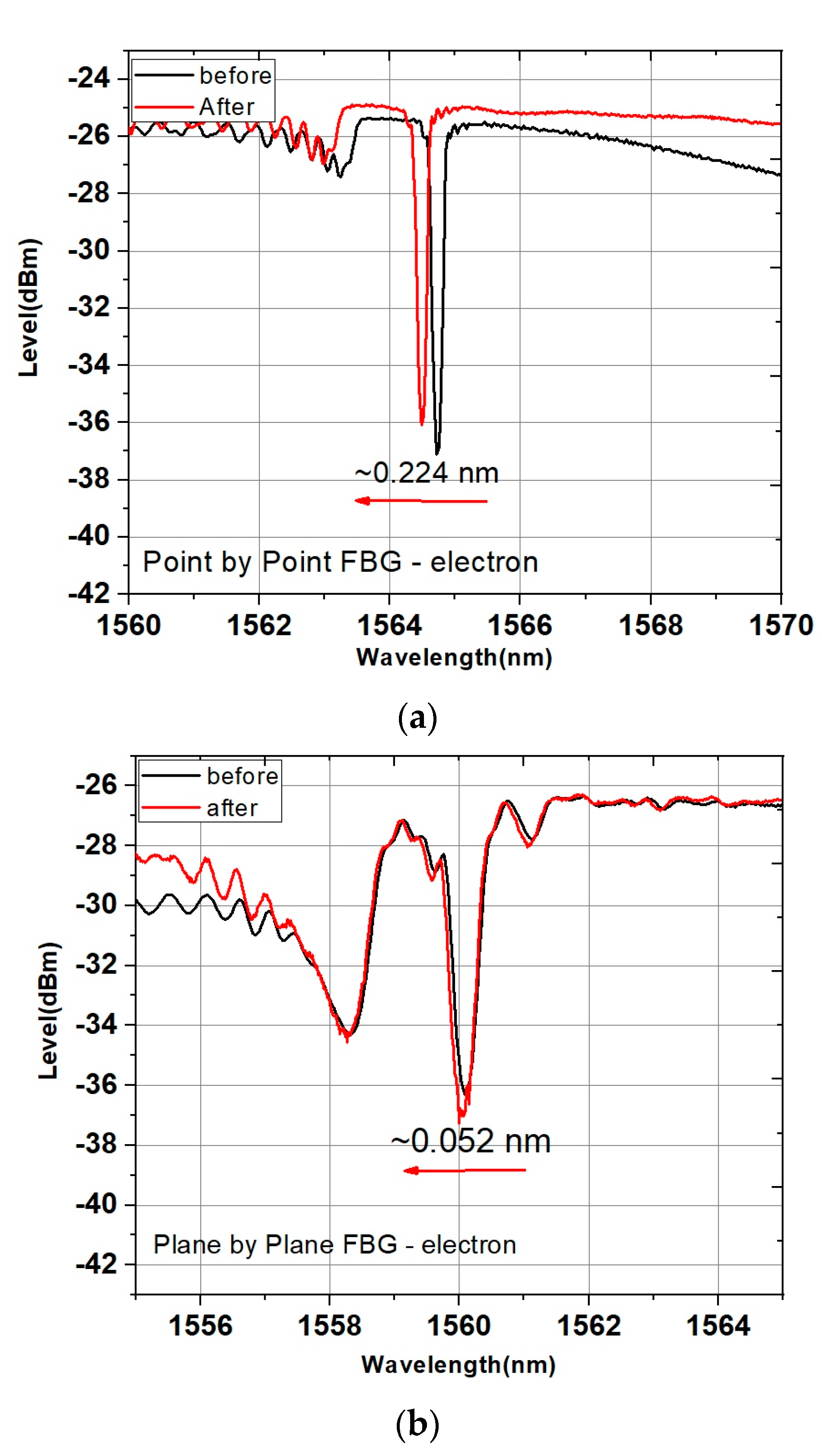
| Before | After | |
|---|---|---|
| Reflectivity (dB) | −11.56 | −11.10 |
| Reflectivity (%) | 93.80 | 92.23 |
| FWHM (nm) | 0.127 nm | 0.119 nm |
| k | 411.27 | 367.64 |
| Δnmod | 0.9752 × 10⁻³ | 0.8720 × 10⁻³ |
| Δλ | −224 pm | |
| Before | After | |
|---|---|---|
| Reflectivity (dB) | −9.94 | −10.77 |
| Reflectivity (%) | 89.86 | 91.61 |
| FWHM (nm) | 0.339 | 0.345 |
| k | 995.79 | 1792.49 |
| Δnmod | 2.3540 × 10⁻³ | 4.2400 × 10⁻³ |
| Δλ | −52 pm | |
Publisher’s Note: MDPI stays neutral with regard to jurisdictional claims in published maps and institutional affiliations. |
© 2021 by the authors. Licensee MDPI, Basel, Switzerland. This article is an open access article distributed under the terms and conditions of the Creative Commons Attribution (CC BY) license (https://creativecommons.org/licenses/by/4.0/).
Share and Cite
Theodosiou, A.; Leal-Junior, A.; Marques, C.; Frizera, A.; Fernandes, A.J.S.; Stancalie, A.; Ioannou, A.; Ighigeanu, D.; Mihalcea, R.; Negut, C.D.; et al. Comparative Study of γ- and e-Radiation-Induced Effects on FBGs Using Different Femtosecond Laser Inscription Methods. Sensors 2021, 21, 8379. https://0-doi-org.brum.beds.ac.uk/10.3390/s21248379
Theodosiou A, Leal-Junior A, Marques C, Frizera A, Fernandes AJS, Stancalie A, Ioannou A, Ighigeanu D, Mihalcea R, Negut CD, et al. Comparative Study of γ- and e-Radiation-Induced Effects on FBGs Using Different Femtosecond Laser Inscription Methods. Sensors. 2021; 21(24):8379. https://0-doi-org.brum.beds.ac.uk/10.3390/s21248379
Chicago/Turabian StyleTheodosiou, Antreas, Arnaldo Leal-Junior, Carlos Marques, Anselmo Frizera, Antonio J. S. Fernandes, Andrei Stancalie, Andreas Ioannou, Daniel Ighigeanu, Razvan Mihalcea, Constantin Daniel Negut, and et al. 2021. "Comparative Study of γ- and e-Radiation-Induced Effects on FBGs Using Different Femtosecond Laser Inscription Methods" Sensors 21, no. 24: 8379. https://0-doi-org.brum.beds.ac.uk/10.3390/s21248379