
Distributed Raman Amplification for Fiber Nonlinearity Compensation in a Mid-Link Optical Phase Conjugation System

 ,
,  ,
,  , ,
, ,
Abstract
:1. Introduction
2. Optimized Distributed Raman Amplification Design over Single Fiber Span
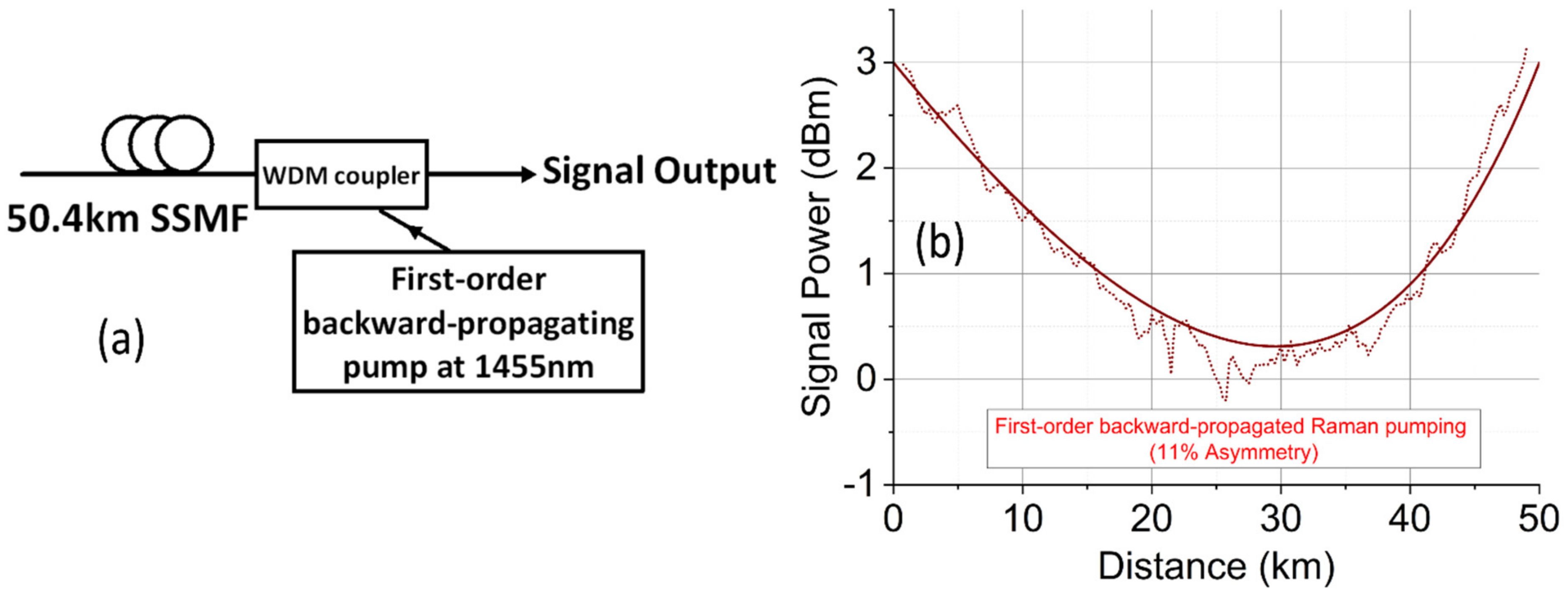
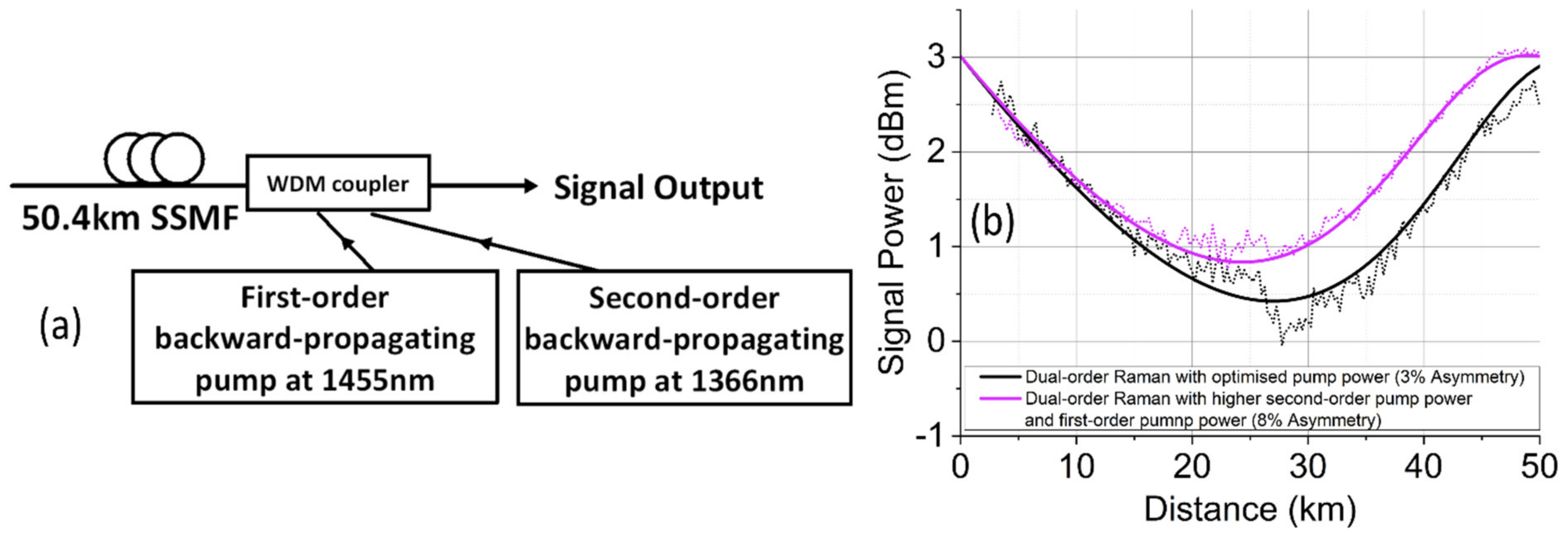
2.1. Distributed Raman Amplification with Backward Pumping Only
2.2. Distributed Raman Amplification with Bidirectional Pumping
3. Optimized Distributed Raman Amplification Design over Multiple Fiber Spans
4. Discussion
5. Conclusions
Author Contributions
Funding
Institutional Review Board Statement
Informed Consent Statement
Data Availability Statement
Acknowledgments
Conflicts of Interest
References
- Minzioni, P.; Cristiani, I.; Degiorgio, V.; Marazzi, L.; Martinelli, M.; Langrock, C.; Fejer, M.M. Experimental Demonstration of Nonlinearity and Dispersion Compensation in an Embedded Link by Optical Phase Conjugation. IEEE Photonics Technol. Lett. 2006, 18, 995–997. [Google Scholar] [CrossRef]
- Tan, M.; Nguyen, T.T.; Rosa, P.; Al-Khateeb, M.A.Z.; Zhang, T.T.; Ellis, A.D. Enhancing the Signal Power Symmetry for Optical Phase Conjugation Using Erbium-Doped-Fiber-Assisted Raman Amplification. IEEE Access 2020, 8, 222766–222773. [Google Scholar] [CrossRef]
- Rosa, P.; Rizzelli, G.; Ania-Castañón, J.D. Link optimization for DWDM transmission with an optical phase conjugation. Opt. Express 2016, 24, 16450–16455. [Google Scholar] [CrossRef] [PubMed]
- Du, L.B.; Morshed, M.M.; Lowery, A.J. Fiber nonlinearity compensation for OFDM super-channels using optical phase conjugation. Opt. Express 2012, 20, 19921. [Google Scholar] [CrossRef] [PubMed]
- Huang, C.; Shu, C. Raman-enhanced optical phase conjugator in WDM transmission systems. Opt. Express 2018, 26, 10274. [Google Scholar] [CrossRef]
- Kaminski, P.; Da Ros, F.; Clausen, A.T.; Forchhammer, S.; Oxenløwe, L.K.; Galili, M. Improved nonlinearity compensation of OPC-aided EDFA-amplified transmission by enhanced dispersion mapping. In Proceedings of the 2020 Conference on Lasers and Electro-Optics (CLEO), San Jose, CA, USA, 10–15 May 2020. [Google Scholar]
- Yoshima, S.; Sun, Y.; Liu, Z.; Bottrill, K.R.H.; Parmigiani, F.; Richardson, D.J.; Petropoulos, P. Mitigation of Nonlinear Effects on WDM QAM Signals Enabled by Optical Phase Conjugation with Efficient Bandwidth Utilization. J. Lightwave Technol. 2017, 35, 971–978. [Google Scholar] [CrossRef] [Green Version]
- Sackey, I.; Schmidt-Langhorst, C.; Elschner, R.; Kato, T.; Tanimura, T.; Watanabe, S.; Hoshida, T.; Schubert, C. Waveband-Shift-Free Optical Phase Conjugator for Spectrally Efficient Fiber Nonlinearity Mitigation. J. Lightwave Technol. 2018, 36, 1309–1317. [Google Scholar] [CrossRef]
- Sackey, I.; Da Ros, F.; Fischer, J.K.; Richter, T.; Jazayerifar, M.; Peucheret, C.; Petermann, K.; Schubert, C. Kerr Nonlinearity Mitigation: Mid-link Spectral Inversion versus Digital Backpropagation in 5x28GBd PDM 16-QAM Signal Transmission. Opt. Express 2014, 22, 27381–27391. [Google Scholar] [CrossRef]
- Jasen, S.L.; van den Borne, D.; Spinnler, B.; Calabro, S.; Suche, H.; Krummrich, P.M.; Sohler, W.; Khoe, G.-D. Optical phase conjugation for ultra long-haul phase-shift-keyed transmission. J. Lightwave Technol. 2006, 24, 54–64. [Google Scholar] [CrossRef] [Green Version]
- Pelusi, M.D. WDM signal All-optical Precompensation of Kerr Nonlinearity in Dispersion-Managed Fibers. IEEE Photonics Technol. Lett. 2013, 25, 71–73. [Google Scholar] [CrossRef]
- Solis-Trapala, K.; Pelusi, M.; Tan, H.N.; Inoue, T.; Namiki, S. Optimized WDM Transmission Impairment Mitigation by Multiple Phase Conjugations. J. Lightwave Technol. 2016, 34, 431–440. [Google Scholar] [CrossRef]
- Solis-Trapala, K.; Inoue, T.; Namiki, S. Signal power asymmetry tolerance of an optical phase conjugation- based nonlinear compensation system. In Proceeding of European Conference and Exhibition on Optical Communication (ECOC), (IEEE, 2014), Cannes, France, 21–25 September 2014. paper We.2.5.4. [Google Scholar]
- Phillips, I.; Tan, M.; Stephens, M.F.; McCarthy, M.; Giacoumidis, E.; Sygletos, S.; Rosa, P.; Fabbri, S.; Le, S.T.; Kanesan, T.; et al. Exceeding the Nonlinear-Shannon Limit using Raman Laser Based Amplification and Optical Phase Conjugation. In Proceedings of the Optical Fiber Communication Conference, OSA Technical Digest, San Francisco, CA, USA, 9–13 March 2014. [Google Scholar]
- Stephens, M.F.C.; Tan, M.; Phillips, I.D.; Sygletos, S.; Harper, P.; Doran, N.J. 1.14Tb/s DP-QPSK WDM polarization-diverse optical phase conjugation. Opt. Express 2014, 22, 11840. [Google Scholar] [CrossRef] [PubMed] [Green Version]
- Da Ros, F.; Yankov, M.P.; Silva, E.P.d.; Pu, M.; Ottaviano, L.; Hu, H.; Semenova, E.; Forchhammer, S.; Zibar, D.; Galili, M.; et al. Characterization and Optimization of a High-Efficiency AlGaAs-On-Insulator-Based Wavelength Convertor for 64- and 256-QAM Signals. J. Lightwave Technol. 2017, 35, 3750–3757. [Google Scholar] [CrossRef] [Green Version]
- Da Ros, F.; Edson, G.; da Silva, E.P.; Peczek, A.; Mai, A.; Petermann, K.; Zimmermann, L.; Oxenløwe, L.K.; Galili, M. Optical Phase Conjugation in a Silicon Waveguide With Lateral p-i-n Diode for Nonlinearity Compensation. J. Lightwave Technol. 2019, 37, 323–329. [Google Scholar] [CrossRef] [Green Version]
- Umeki, T.; Kazama, T.; Sano, A.; Shibahara, K.; Suzuki, K.; Abe, M.; Takenouchi, H.; Miyamoto, Y. Simultaneous nonlinearity mitigation in 92 × 180-Gbit/s PDM-16QAM transmission over 3840 km using PPLN-based guard-band-less optical phase conjugation. Opt. Express 2016, 24, 16945. [Google Scholar] [CrossRef]
- Hu, H.; Jopson, R.M.; Gnauck, A.H.; Randel, S.; Chandrasekhar, S. Fiber nonlinearity mitigation of WDM-PDM QPSK/16-QAM signals using fiber-optic parametric amplifiers based multiple optical phase conjugations. Opt. Express 2017, 25, 1618. [Google Scholar] [CrossRef] [Green Version]
- Namiki, S.; Solis-Trapala, K.; Tan, H.N.; Pelusi, M.; Inoue, T. Multi-Channel Cascadable Parametric Signal Processing for Wavelength Conversion and Nonlinearity Compensation. J. Lightwave Technol. 2017, 35, 815–823. [Google Scholar] [CrossRef] [Green Version]
- Ellis, A.D.; McCarthy, M.E.; Al-Khateeb, M.A.Z.; Sorokina, M.; Doran, N.J. Performance limits in optical communications due to fiber nonlinearity. Adv. Opt. Photonics 2019, 9, 429–503. [Google Scholar] [CrossRef] [Green Version]
- Tan, M.; Al-Khateeb, M.A.Z.; Iqbal, M.A.; Ellis, A.D. Distributed Raman Amplification for Combating Optical Nonlinearities in Fibre Transmission. In Proceeding of 2018 Conference on Lasers and Electro-Optics Pacific Rim (CLEO-PR), Hong Kong, China, 29 July–3 August 2018. [Google Scholar]
- Al-Khateeb, M.; Tan, M.; Zhang, T.; Ellis, A. Combating Fiber Nonlinearity Using Dual-Order Raman Amplification and OPC. IEEE Photonics Technol. Lett. 2019, 31, 877–880. [Google Scholar] [CrossRef]
- Bidaki, E.; Kumar, S. A Raman-pumped Dispersion and Nonlinearity Compensating Fiber for Fiber Optic Communications. IEEE Photonics J. 2020, 12, 720017. [Google Scholar] [CrossRef]
- Al-Khateeb, M.A.Z.; Tan, M.; Iqbal, M.A.; Ali, A.; McCarthy, M.E.; Harper, P.; Ellis, A.D. Experimental demonstration of 72% reach enhancement of 3.6Tbps optical transmission system using mid-link optical phase conjugation. Opt. Express 2018, 26, 23960–23968. [Google Scholar] [CrossRef] [PubMed]
- Ellis, A.D.; Tan, M.; Iqbal, M.A.; Al-Khateeb, M.A.Z.; Gordienko, V.; Mondaca, G.S.; Fabbri, S.; Stephens, M.F.C.; McCarthy, M.E.; Perentos, A.; et al. 4 Tb/s Transmission Reach Enhancement Using 10 × 400 Gb/s Super-Channels and Polarization Insensitive Dual Band Optical Phase Conjugation. J. Lightwave Technol. 2016, 34, 1717–1723. [Google Scholar] [CrossRef] [Green Version]
- Al-Khateeb, M.A.Z.; Iqbal, M.A.; Tan, M.; Ali, A.; McCarthy, M.E.; Harper, P.; Ellis, A.D. Analysis of the nonlinear Kerr effects in optical transmission systems that deploy optical phase conjugation. Opt. Express 2018, 26, 3145–3160. [Google Scholar] [CrossRef] [PubMed]
- Tan, M.; Al-Khateeb, M.A.Z.; Zhang, T.T.; Ellis, A.D. Fiber Nonlinearity Compensation Using Erbium-Doped-Fiber-Assisted Dual-Order Raman Amplification. In Proceeding of 2019 Conference on Lasers and Electro-Optics (CLEO), San Jose, CA, USA, 1 May 2019. [Google Scholar]
- Rosa, P.; Le, S.T.; Rizzelli, G.; Tan, M.; Harper, P.; Ania-Castañón, J.D. Signal power asymmetry optimisation for optical phase conjugation using Raman amplification. Opt. Express 2015, 23, 31772–31778. [Google Scholar] [CrossRef] [PubMed] [Green Version]
- Bissessur, H. Amplifier technologies for unrepeatered links, submarine transmissions. In Proceedings of the Optical Fiber Communication Conference and Exposition and the National Fiber Optic Engineers Conference (OFC/NFOEC), Anaheim, CA, USA, 17–21 March 2013. [Google Scholar]
- Tan, M.; Iqbal, M.A.; Nguyen, T.T.; Rosa, P.; Krzczanowicz, L.; Phillips, I.D.; Harper, P.; Forysiak, W. Raman Amplification Optimization in Short-Reach High Data Rate Coherent Transmission Systems. Sensors 2021, 21, 6521. [Google Scholar] [CrossRef]
- Toyoda, K.; Koizumi, Y.; Omiya, T.; Yoshida, M.; Hirooka, T.; Nakazawa, M. Marked performance improvement of 256QAM transmission using a digital back-propagation method. Opt. Express 2012, 20, 19821–19851. [Google Scholar] [CrossRef]
- Galdino, L.; Tan, M.; Alvarado, A.; Lavery, D.; Rosa, P.; Maher, R.; Ania-Castanon, J.D.; Harper, P.; Makovejs, S.; Thomesn, B.C.; et al. Amplification schemes and multi-channel DBP for unrepeatered transmission. J. Lightwave Technol. 2016, 34, 2221–2227. [Google Scholar] [CrossRef] [Green Version]
- Papernyi, S.B.; Xvnnov, V.B.; Koyano, Y.; Yamamoto, H. Sixth-order cascaded Raman amplification. In Proceedings of the OFC/NFOEC Technical Digest. Optical Fiber Communication Conference, Anaheim, CA, USA, 6 March 2005. [Google Scholar]
- Tan, M.; Rosa, P.; Phillips, I.D.; Harper, P. Extended Reach of 116 Gb/s DP-QPSK Transmission using Random DFB Fiber Laser Based Raman Amplification and Bidirectional Second-order Pumping. In Proceedings of the Optical Fiber Communication Conference, OSA Technical Digest, Los Angeles, CA, USA, 22–26 March 2015. [Google Scholar]
- Tan, M.; Rosa, P.; Le, S.T.; Iqbal, M.A.; Phillips, I.D.; Harper, P. Transmission performance improvement using random DFB laser based Raman amplification and bidirectional second-order pumping. Opt. Express 2016, 24, 2215–2221. [Google Scholar] [CrossRef]
- Iqbal, M.A.; Tan, M.; Harper, P. Enhanced transmission performance using backward-propagated broadband ase pump. IEEE Photonics Technol. Lett. 2018, 30, 865–868. [Google Scholar] [CrossRef] [Green Version]
- Rosa, P.; Rizzelli, G.; Tan, M.; Harper, P.; Ania-Castañón, J.D. Characterisation of random DFB Raman laser amplifier for WDM transmission. Opt. Express 2015, 23, 28634–28639. [Google Scholar] [CrossRef] [Green Version]
- Tan, M.; Rosa, P.; Iqbal, M.A.; Phillips, I.D.; Nuno, J.; Ania-Castañón, J.D.; Harper, P. RIN mitigation in second-order pumped Raman fibre laser based amplification. In Proceedings of the Asia Communications and Photonics Conference, OSA Technical Digest (Optical Society of America, 2015), Hong Kong, China, 19–23 November 2015. paper AM2E.6. [Google Scholar]
- Tan, M.; Rosa, P.; Le, S.T.; Dvoyrin, V.V.; Iqbal, M.A.; Sugavanam, S.; Turitsyn, S.K.; Harper, P. RIN mitigation and transmission performance enhancement with forward broadband pump. IEEE Photonics Technol. Lett. 2018, 30, 254–257. [Google Scholar] [CrossRef]
- Rizzelli, G.; Iqbal, M.A.; Gallazzi, F.; Rosa, P.; Tan, M.; Ania-Castañón, J.D.; Krzczanowicz, L.; Corredera, P.; Phillips, I.; Forysiak, W.; et al. Impact of input FBG reflectivity and forward pump power on RIN transfer in ultralong Raman laser amplifiers. Opt. Express 2016, 24, 29170–29175. [Google Scholar] [CrossRef] [PubMed] [Green Version]
- Tan, M.; Rosa, P.; Phillips, I.D.; Harper, P. Long-haul Transmission Performance Evaluation of Ultra-long Raman Fiber Laser Based Amplification Influenced by Second Order Co-pumping. In Proceeding of Asia Communications and Photonics Conference, OSA Technical Digest (online) (Optical Society of America, 2014), Shanghai, China, 11–14 November 2014. paper ATh1E.4. [Google Scholar]
- Tan, M.; Rosa, P.; Le, S.T.; Phillips, I.D.; Harper, P. Evaluation of 100g DP-QPSK long-haul transmission performance using second order co-pumped Raman laser based amplification. Opt. Express 2015, 23, 22181–22189. [Google Scholar] [CrossRef] [PubMed] [Green Version]
- Ania-Castañón, J.D.; Karalekas, V.; Harper, P.; Turitsyn, S.K. Simultaneous spatial and spectral transparency in ultralong fiber lasers. Phys. Rev. Lett. 2008, 101, 123903. [Google Scholar] [CrossRef] [Green Version]
- Hazarika, P.; Tan, M.; Iqbal, M.A.; Krzczanowicz, L.; Ali, A.; Phillips, I.D.; Harper, P.; Forysiak, W. RIN induced penalties in G.654.E and G.652.D based distributed Raman amplifiers for coherent transmission systems. Opt. Express 2021, 29, 32081–32088. [Google Scholar] [CrossRef] [PubMed]
- Cheng, J.; Tang, M.; Lau, A.P.T.; Lu, C.; Wang, L.; Dong, Z.; Bilal, S.B.; Fu, S.; Shum, P.P.; Liu, D. Pump RIN-induced impairments in unrepeatered transmission systems using distributed Raman amplifier. Opt. Express 2015, 23, 11838–11854. [Google Scholar] [CrossRef] [PubMed]
- Rosa, P.; Tan, M.; Le, S.T.; Phillips, I.D.; Ania-Castañón, J.; Sygletos, S.; Harper, P. Unrepeatered DP-QPSK Transmission Over 352.8 km SMF Using Random DFB Fiber Laser Amplification. IEEE Photonics Technol. Lett. 2015, 27, 1189–1192. [Google Scholar] [CrossRef] [Green Version]
- Rosa, P.; Rizzelli, G.; Pang, X.; Ozolins, O.; Udalcovs, A.; Tan, M.; Jaworski, M.; Marciniak, M.; Sergeyev, S.; Schatz, R.; et al. Unrepeatered 240-km 64-QAM Transmission Using Distributed Raman Amplification over SMF Fiber. Appl. Sci. 2020, 10, 1433. [Google Scholar] [CrossRef] [Green Version]
- Bouteiller, J.-C.; Brar, K.; Headley, C. Quasi-constant Signal Power Transmission. In Proceeding of ECOC, Copenhagen, Demark, 8–12 September 2002. paper Symposium 3.4. [Google Scholar]
- Bouteiller, J.-C.; Brar, K.; Bromage, J.; Radic, S.; Headley, C. Dual-order Raman pump. IEEE Photonics Technol. Lett. 2003, 15, 212–214. [Google Scholar] [CrossRef]
- Lundberg, L.; Andrekson, P.; Karlsson, M. Power consumption analysis of Hybrid EDFA/Raman amplifiers in long-haul transmission systems. J. Lightwave Technol. 2017, 35, 2132–2142. [Google Scholar] [CrossRef]
- Frauk, M.S.; Savory, S.J. Digital Signal Processing for Coherent Transceivers Employing Multilevel Formats. J. Lightwave Technol. 2017, 35, 1125–1141. [Google Scholar] [CrossRef] [Green Version]
- Zhang, J.; Li, X.; Dong, Z. Digital Nonlinear Compensation Based on the Modified Logarithmic Step Size. J. Lightwave Technol. 2013, 31, 3546–3555. [Google Scholar] [CrossRef]
- Nguyen, T.T.; Zhang, T.; Giacoumidis, E.; Ali, A.; Tan, M.; Harper, P.; Barry, L.; Ellis, A. Coupled Transceiver-Fiber Nonlinearity Compensation Based on Machine Learning for Probabilistic Shaping System. J. Lightwave Technol. 2021, 39, 388–399. [Google Scholar] [CrossRef]
- Ellis, A.D.; McCarthy, M.E.; Al-Khateeb, M.A.Z.; Sygletos, S. Capacity limits of systems employing multiple optical phase conjugators. Opt. Express 2015, 23, 20381–20393. [Google Scholar] [CrossRef] [PubMed] [Green Version]


| Span Lengths | Raman Pumping Schemes | Optimum Signal Power Profile Symmetry |
|---|---|---|
| 25 km | First-order bidirectional pumping | 97% [12] |
| 50 km | Dual-order backward pumping | 97% [23] |
| 62 km | Second-order bidirectional pumping with random fiber laser | 97% [29] |
| 100 km | Second-order bidirectional pumping with random fiber laser | 72% [29] |
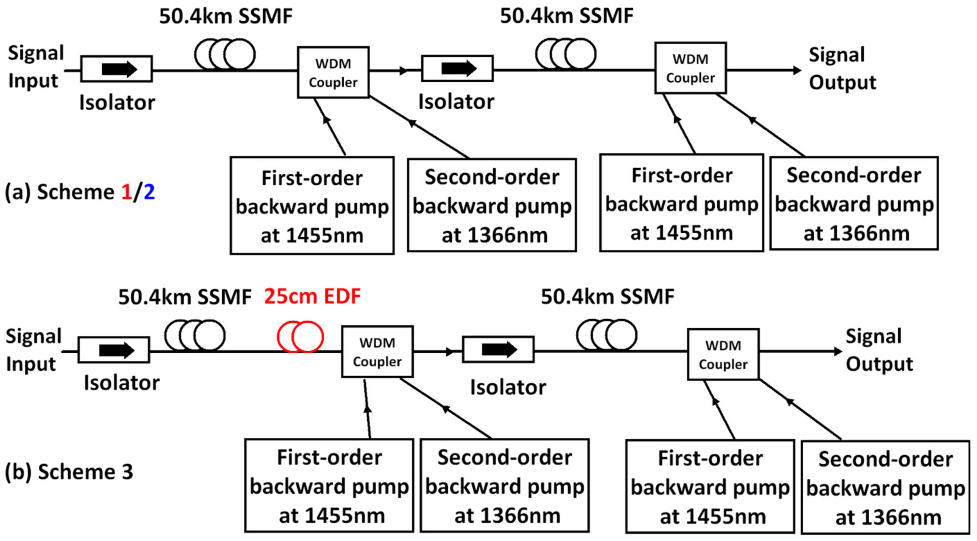
| 2 × 50 km | Dual-order backward pumping with EDF in the first span, no EDF in the second span | 93% [2] |
Publisher’s Note: MDPI stays neutral with regard to jurisdictional claims in published maps and institutional affiliations. |
© 2022 by the authors. Licensee MDPI, Basel, Switzerland. This article is an open access article distributed under the terms and conditions of the Creative Commons Attribution (CC BY) license (https://creativecommons.org/licenses/by/4.0/).
Share and Cite
Tan, M.; Rosa, P.; Nguyen, T.T.; Al-Khateeb, M.A.Z.; Iqbal, M.A.; Xu, T.; Wen, F.; Ania-Castañón, J.D.; Ellis, A.D. Distributed Raman Amplification for Fiber Nonlinearity Compensation in a Mid-Link Optical Phase Conjugation System. Sensors 2022, 22, 758. https://0-doi-org.brum.beds.ac.uk/10.3390/s22030758
Tan M, Rosa P, Nguyen TT, Al-Khateeb MAZ, Iqbal MA, Xu T, Wen F, Ania-Castañón JD, Ellis AD. Distributed Raman Amplification for Fiber Nonlinearity Compensation in a Mid-Link Optical Phase Conjugation System. Sensors. 2022; 22(3):758. https://0-doi-org.brum.beds.ac.uk/10.3390/s22030758
Chicago/Turabian StyleTan, Mingming, Paweł Rosa, Tu T. Nguyen, Mohammad A. Z. Al-Khateeb, Md. Asif Iqbal, Tianhua Xu, Feng Wen, Juan D. Ania-Castañón, and Andrew D. Ellis. 2022. "Distributed Raman Amplification for Fiber Nonlinearity Compensation in a Mid-Link Optical Phase Conjugation System" Sensors 22, no. 3: 758. https://0-doi-org.brum.beds.ac.uk/10.3390/s22030758