
Negative Index Metamaterial-Based Frequency-Reconfigurable Textile CPW Antenna for Microwave Imaging of Breast Cancer

 ,
,  ,
,  , ,
, , 
Abstract
:1. Introduction
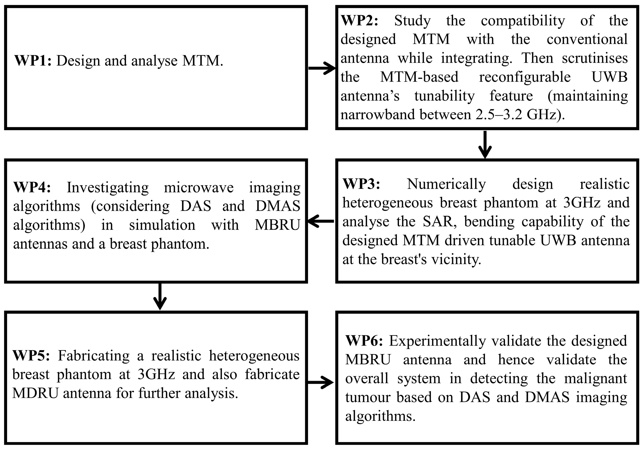
2. Overview of Workflow
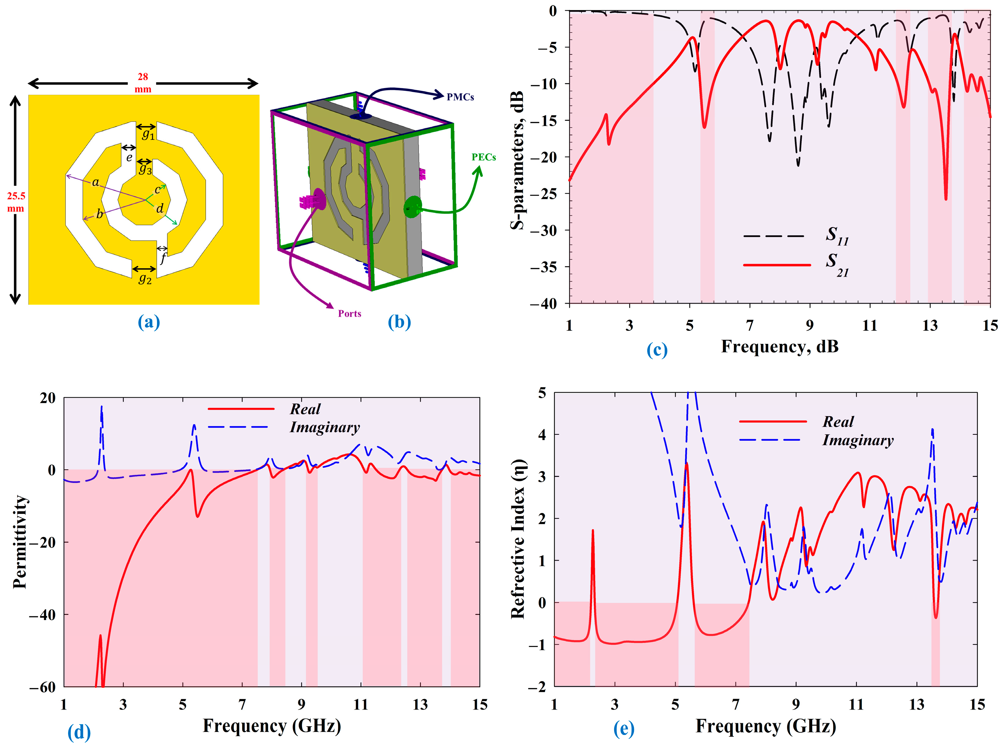
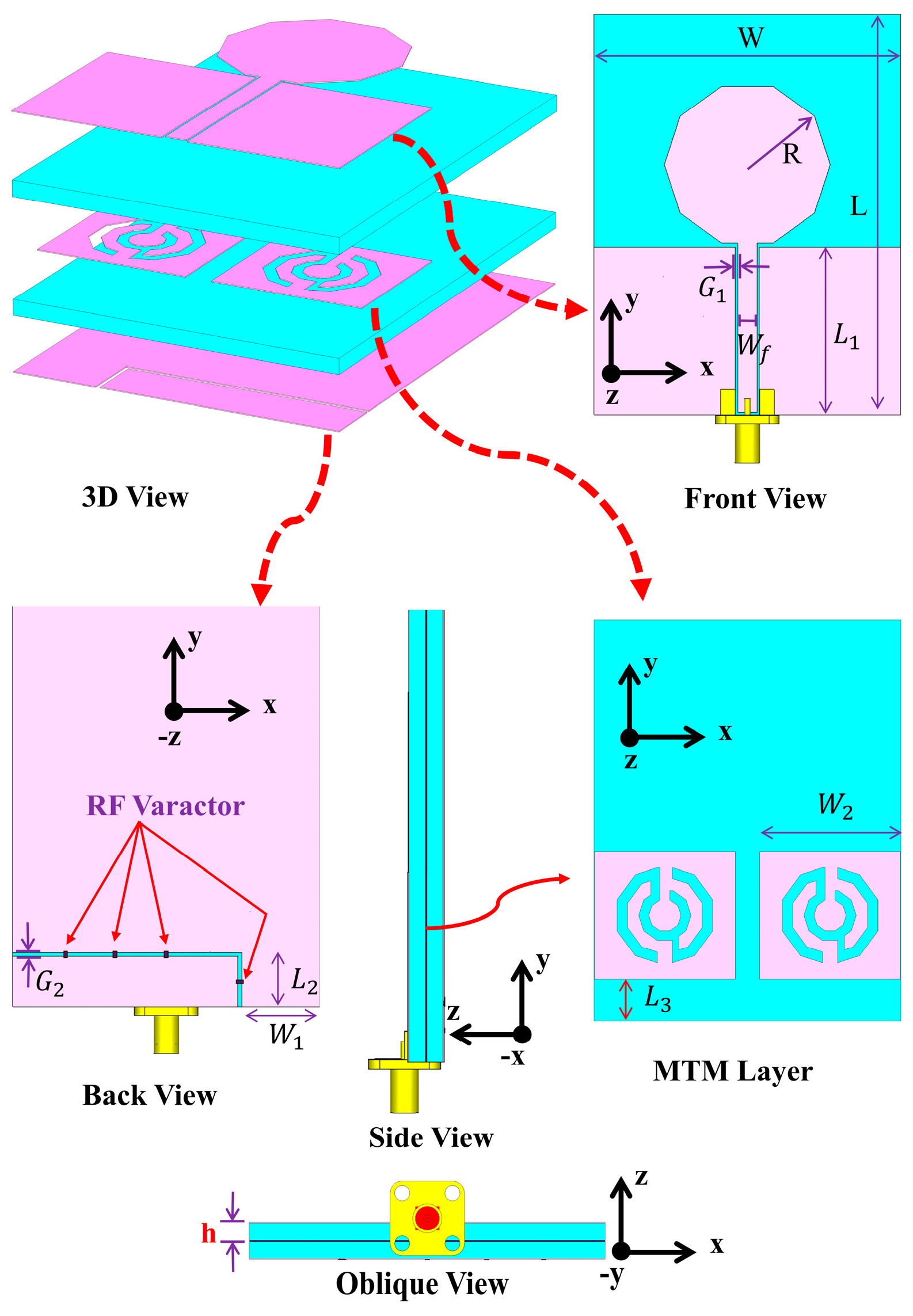
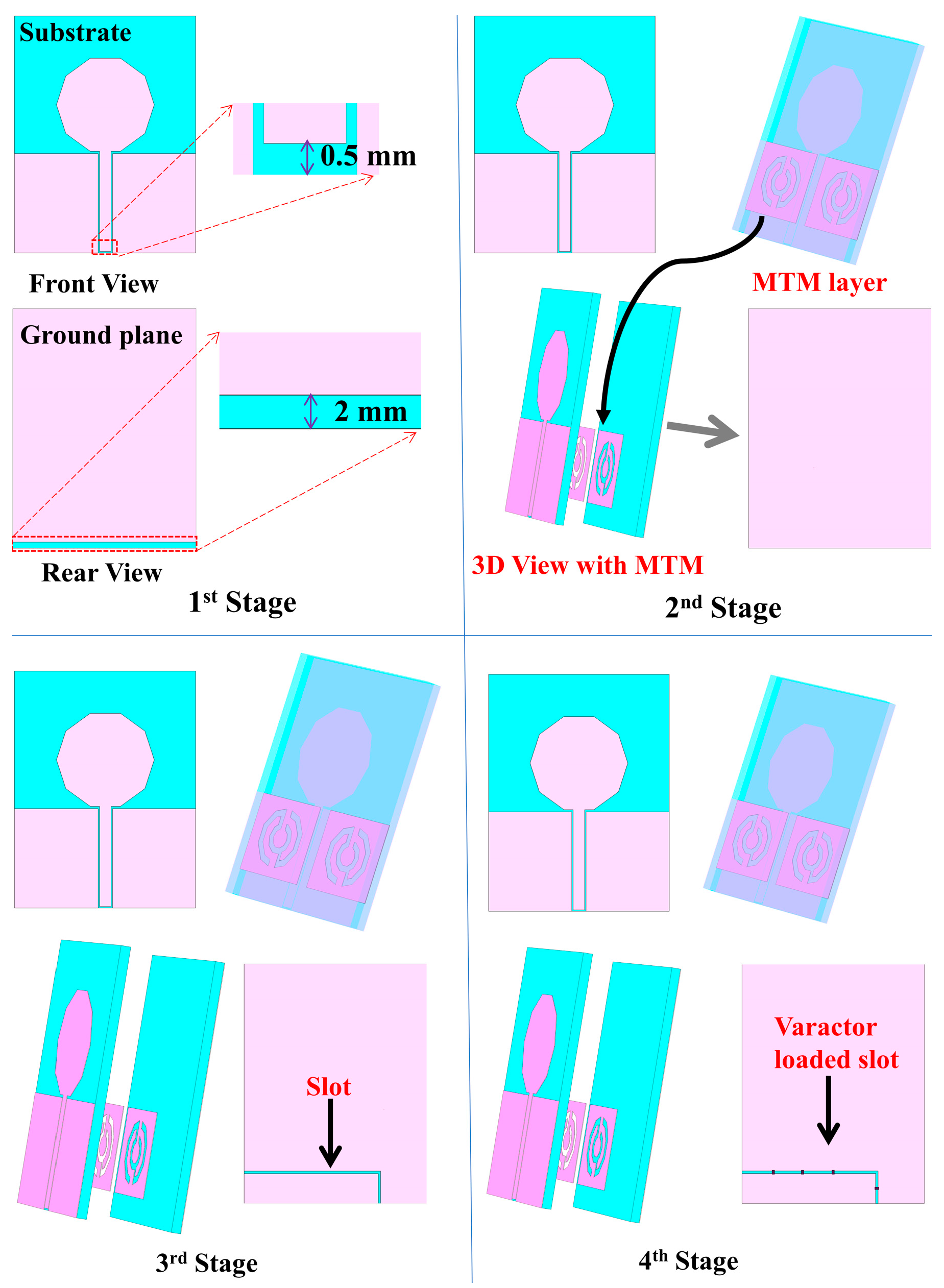
3. Metamaterial-Based Reconfigurable Antenna Design
3.1. Results of the Proposed MBRU Antenna
3.1.1. Study on Bending Analysis and SAR
3.1.2. Effect of the MBRU Antenna in the Vicinity of the Human Tissue
4. Heterogeneous Breast Model Design
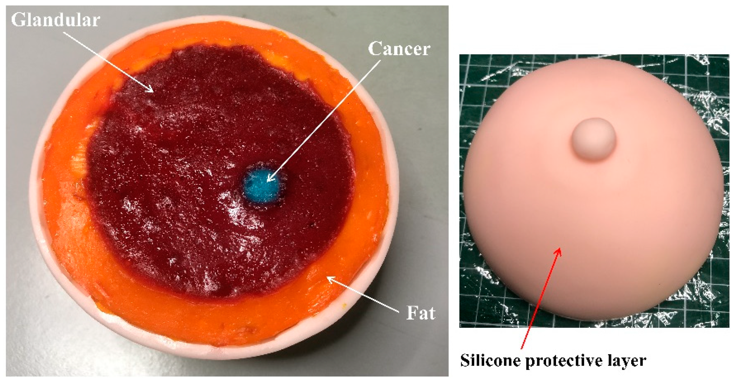
Heterogenous Breast Phantom Fabrication
5. Proposed MBRU Antenna-Based Microwave Imaging System
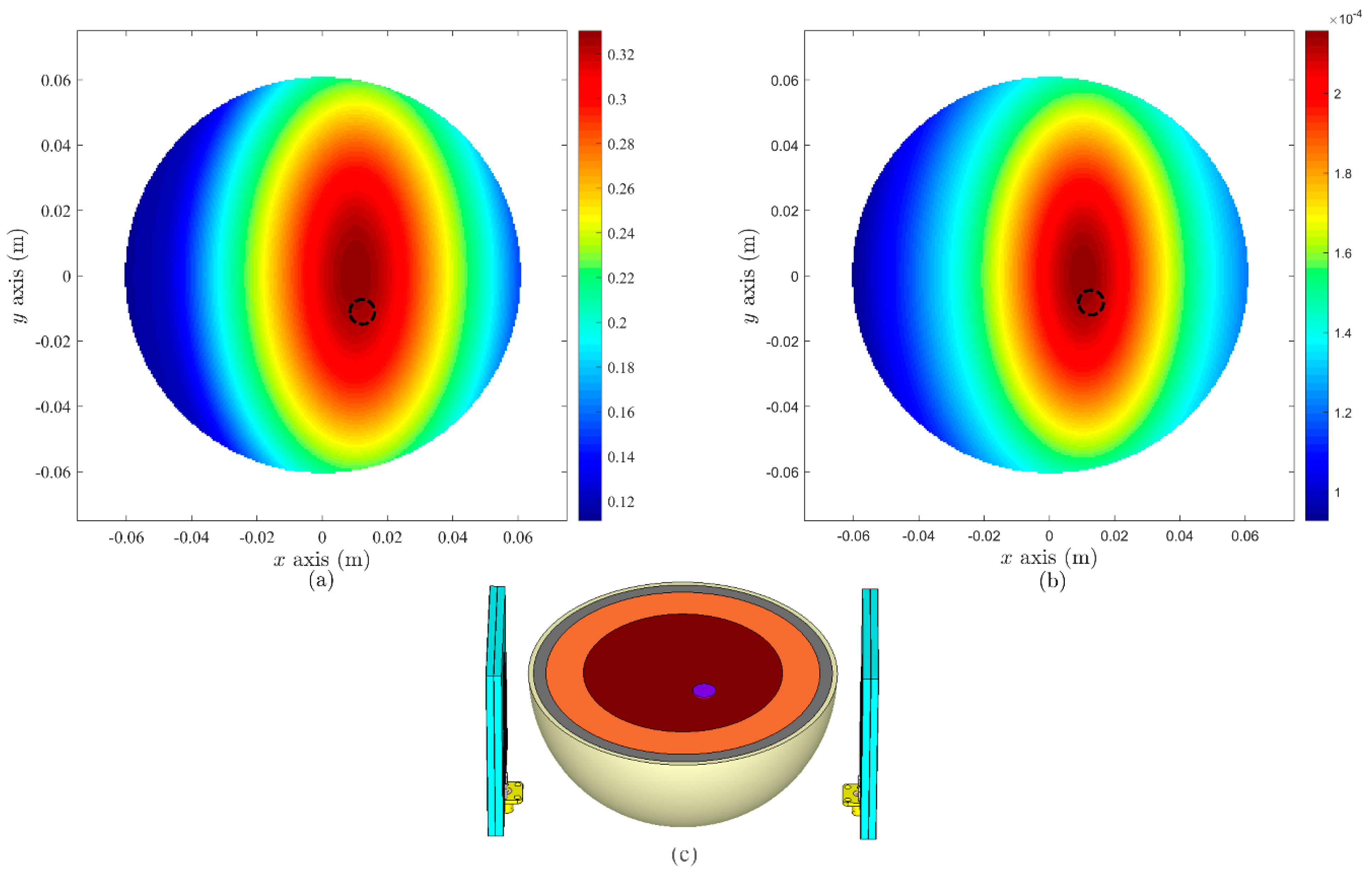
5.1. Simulation-Based Setup
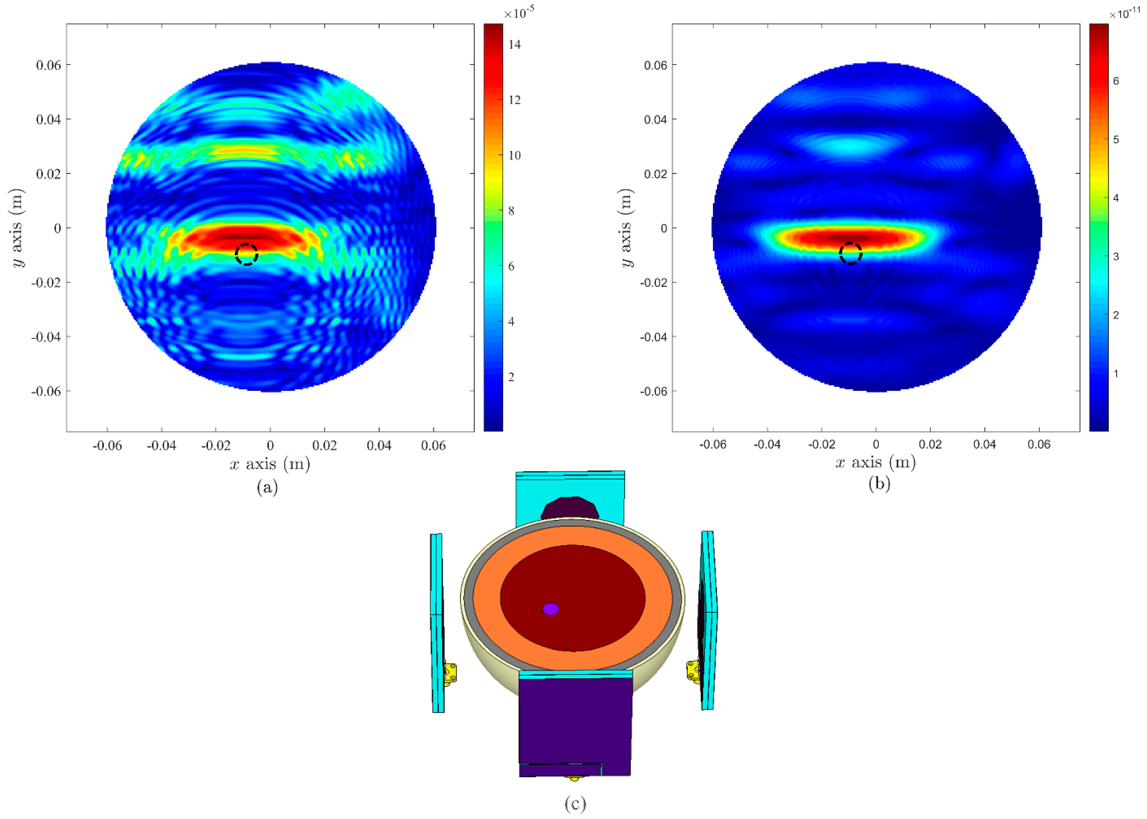
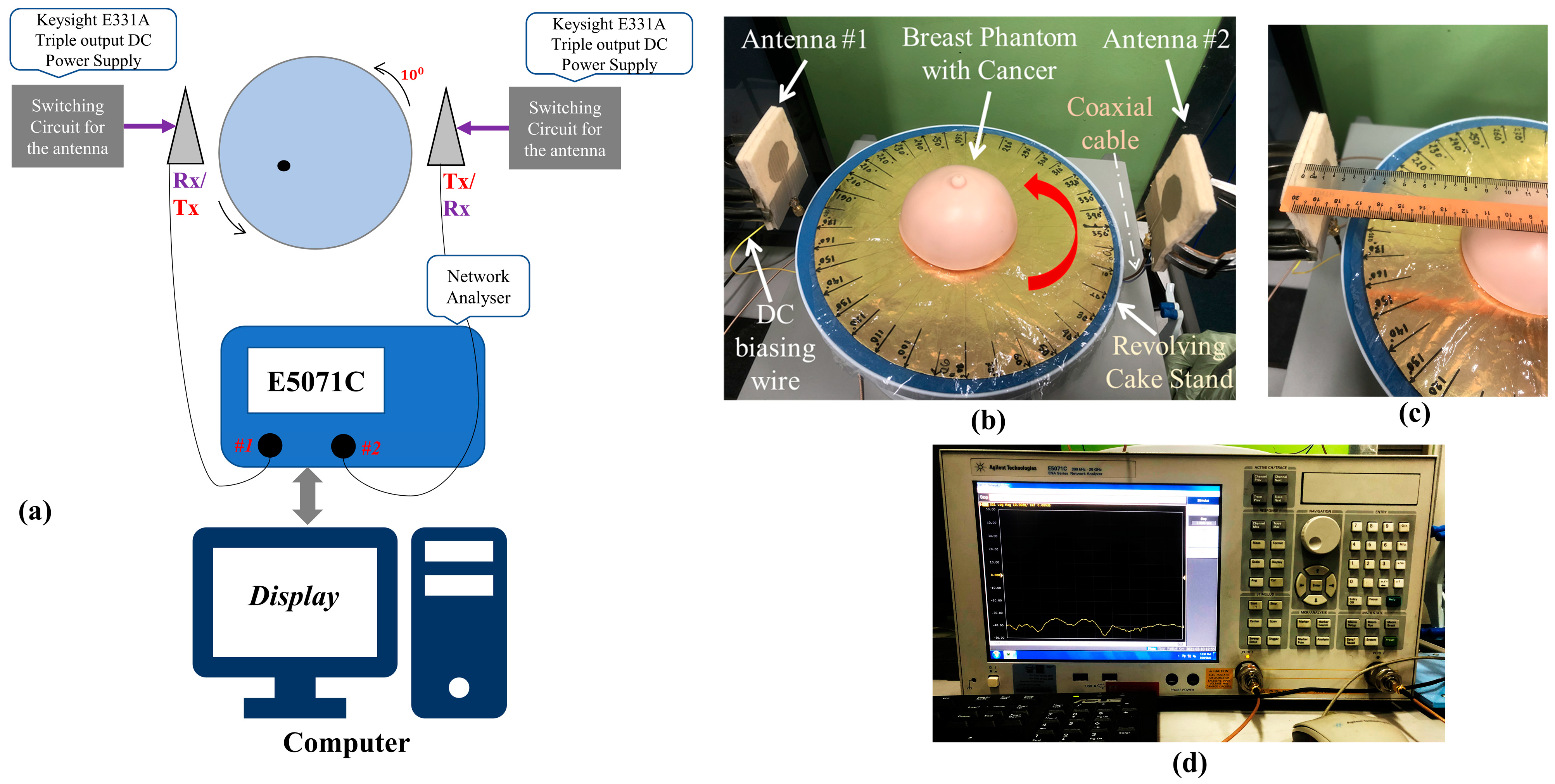
5.2. Experimental Setup
6. Conclusions
Author Contributions
Funding
Institutional Review Board Statement
Informed Consent Statement
Data Availability Statement
Conflicts of Interest
References
- Sung, H.; Ferlay, J.; Siegel, R.L.; Laversanne, M.; Soerjomataram, I.; Jemal, A.; Bray, F. Global cancer statistics 2020: GLOBOCAN estimates of incidence and mortality worldwide for 36 cancers in 185 countries. CA Cancer J. Clin. 2021, 71, caac.21660. [Google Scholar] [CrossRef] [PubMed]
- Crosby, D.; Lyons, N.; Greenwood, E.; Harrison, S.; Hiom, S.; Moffat, J.; Quallo, T.; Samuel, E.; Walker, I. A roadmap for the early detection and diagnosis of cancer. Lancet Oncol. 2020, 21, 1397–1399. [Google Scholar] [CrossRef]
- Ginsburg, O.; Yip, C.; Brooks, A.; Cabanes, A.; Caleffi, M.; Dunstan Yataco, J.A.; Gyawali, B.; McCormack, V.; McLaughlin de Anderson, M.; Mehrotra, R.; et al. Breast cancer early detection: A phased approach to implementation. Cancer 2020, 126, 2379–2393. [Google Scholar] [CrossRef]
- Islam, M.T.; Mahmud, M.Z.; Islam, M.T.; Kibria, S.; Samsuzzaman, M. A Low Cost and Portable Microwave Imaging System for Breast Tumor Detection Using UWB Directional Antenna array. Sci. Rep. 2019, 9, 15491. [Google Scholar] [CrossRef] [Green Version]
- Mahmud, M.; Islam, M.; Misran, N.; Almutairi, A.; Cho, M. Ultra-Wideband (UWB) Antenna Sensor Based Microwave Breast Imaging: A Review. Sensors 2018, 18, 2951. [Google Scholar] [CrossRef] [Green Version]
- Bahramiabarghouei, H.; Porter, E.; Santorelli, A.; Gosselin, B.; Popovíc, M.; Rusch, L.A. Flexible 16 antenna array for microwave breast cancer detection. IEEE Trans. Biomed. Eng. 2015, 62, 2516–2525. [Google Scholar] [CrossRef]
- Nikolova, N.K. Microwave imaging for breast cancer. IEEE Microw. Mag. 2011, 12, 78–94. [Google Scholar] [CrossRef]
- Zhang, K.; Soh, P.J.; Yan, S. Meta-Wearable Antennas—A Review of Metamaterial Based Antennas in Wireless Body Area Networks. Materials 2020, 14, 149. [Google Scholar] [CrossRef] [PubMed]
- Kapetanakis, T.N.; Nikolopoulos, C.D.; Petridis, K.; Vardiambasis, I.O. Wearable textile antenna with a graphene sheet or conductive fabric patch for the 2.45 GHz band. Electronics 2021, 10, 2571. [Google Scholar] [CrossRef]
- Memon, A.W.; de Paula, I.L.; Malengier, B.; Vasile, S.; Van Torre, P.; Van Langenhove, L. Breathable textile rectangular ring microstrip patch antenna at 2.45 ghz for wearable applications. Sensors 2021, 21, 1635. [Google Scholar] [CrossRef]
- Hossain, K.; Sabapathy, T.; Jusoh, M.; Abdelghany, M.A.; Soh, P.J.; Osman, M.N.; Yasin, M.N.M.; Rahim, H.A.; Al-Bawri, S.S. A Negative Index Nonagonal CSRR Metamaterial-Based Compact Flexible Planar Monopole Antenna for Ultrawideband Applications Using Viscose-Wool Felt. Polymers 2021, 13, 2819. [Google Scholar] [CrossRef] [PubMed]
- Islam, M.M.O.; Faruque, M.R.I.; Islam, M.T.; Mansor, M.F. Compact and broadband antenna using double-negative transmission line metamaterial. Appl. Phys. A Mater. Sci. Process. 2017, 123, 21. [Google Scholar] [CrossRef]
- Engheta, N.; Ziolkowski, R.W. Metamaterials: Physics and Engineering Explorations; John Wiley & Sons, Inc.: Hoboken, NJ, USA, 2006; ISBN 9780471784197. [Google Scholar]
- Hossain, K.; Sabapathy, T.; Jusoh, M.; Soh, P.J.; Fazilah, A.F.M.; Halim, A.A.A.; Raghava, N.S.; Podilchak, S.K.; Schreurs, D.; Abbasi, Q.H. ENG and NZRI Characteristics of Decagonal-Shaped Metamaterial for Wearable Applications. In Proceedings of the 2020 International Conference on UK-China Emerging Technologies (UCET), Glasgow, UK, 20–21 August 2020; IEEE: Glasgow, UK, 2020; pp. 1–4. [Google Scholar]
- Alemaryeen, A.; Noghanian, S. Crumpling effects and specific absorption rates of flexible AMC integrated antennas. IET Microw. Antennas Propag. 2018, 12, 627–635. [Google Scholar] [CrossRef] [Green Version]
- Ahdi Rezaeieh, S.; Antoniades, M.A.; Abbosh, A.M. Gain Enhancement of Wideband Metamaterial-Loaded Loop Antenna with Tightly Coupled Arc-Shaped Directors. IEEE Trans. Antennas Propag. 2017, 65, 2090–2095. [Google Scholar] [CrossRef]
- Hossain, K.; Sabapathy, T.; Jusoh, M.; Soh, P.J.; Osman, M.N.; Al-Bawri, S.S. A Compact Wideband CSRR Near Zero Refractive Index and Epsilon Negative Metamaterial for Wearable Microwave Applications. J. Phys. Conf. Ser. 2021, 1962, 012019. [Google Scholar] [CrossRef]
- Islam, M.M.T.; Islam, M.M.T.; Samsuzzaman, M.; Faruque, M.R.I. Compact metamaterial antenna for UWB applications. Electron. Lett. 2015, 51, 1222–1224. [Google Scholar] [CrossRef]
- Mersani, A.; Osman, L.; Ribero, J.M. Flexible UWB AMC antenna for early stage skin cancer identification. Prog. Electromagn. Res. M 2019, 80, 71–81. [Google Scholar] [CrossRef] [Green Version]
- Islam, M.M.; Islam, M.T.; Faruque, M.R.I.; Samsuzzaman, M.; Misran, N.; Arshad, H. Microwave imaging sensor using compact metamaterial UWB antenna with a high correlation factor. Materials 2015, 8, 4631–4651. [Google Scholar] [CrossRef] [PubMed] [Green Version]
- Hossain, K.; Sabapathy, T.; Jusoh, M.; Soh, P.J.; Jamaluddin, M.H.; Al-Bawri, S.S.; Osman, M.N.; Ahmad, R.B.; Rahim, H.A.; Mohd Yasin, M.N.; et al. Electrically Tunable Left-Handed Textile Metamaterial for Microwave Applications. Materials 2021, 14, 1274. [Google Scholar] [CrossRef]
- Christodoulou, C.G.; Tawk, Y.; Lane, S.A.; Erwin, S.R. Reconfigurable antennas for wireless and space applications. Proc. IEEE 2012, 100, 2250–2261. [Google Scholar] [CrossRef]
- Majid, H.A.; Abdul Rahim, M.K.; Hamid, M.R.; Murad, N.A.; Ismail, M.F. Frequency-Reconfigurable Microstrip Patch-Slot Antenna. IEEE Antennas Wirel. Propag. Lett. 2013, 12, 218–220. [Google Scholar] [CrossRef]
- Hossain, K.; Sabapathy, T.; Jusoh, M.; Soh, P.J.; Osman, M.N.; Yasin, M.N.M.; Rahim, H.A.; Hodgkinson, C.J.; Podilchak, S.K. Pattern-Reconfigurable PCB-based Phased Array for WLAN Applications. In Proceedings of the 2020 9th Asia-Pacific Conference on Antennas and Propagation (APCAP), Xiamen, China, 4–7 August 2020; IEEE: Xiamen, China, 2020; pp. 1–2. [Google Scholar]
- Hossain, K.; Sabapathy, T.; Jusoh, M.; Soh, P.J.; Ahmad, R.B.; Jais, M.I.; Osman, M.N.; Yasin, M.N.M.; Rahim, H.A.; Saluja, N.; et al. A Frequency-Reconfigurable Microstrip Antenna with Constant Dipole-Like Radiation Patterns Using Single Bias, Triple Varactor Tuning with Reduced Complexity. Wirel. Pers. Commun. 2021, 1–22. [Google Scholar] [CrossRef]
- Islam, M.T.; Samsuzzaman, M.; Kibria, S.; Misran, N.; Islam, M.T. Metasurface Loaded High Gain Antenna based Microwave Imaging using Iteratively Corrected Delay Multiply and Sum Algorithm. Sci. Rep. 2019, 9, 17317. [Google Scholar] [CrossRef] [Green Version]
- Islam, M.T.; Samsuzzaman, M.; Islam, M.T.; Kibria, S.; Singh, M.J. A homogeneous breast phantom measurement system with an improved modified microwave imaging antenna sensor. Sensors 2018, 18, 2962. [Google Scholar] [CrossRef] [PubMed] [Green Version]
- Kibria, S.; Samsuzzaman, M.; Islam, M.T.; Mahmud, M.Z.; Misran, N.; Islam, M.T. Breast phantom imaging using iteratively corrected coherence factor delay and sum. IEEE Access 2019, 7, 40822–40832. [Google Scholar] [CrossRef]
- Islam, M.T.; Samsuzzaman, M.; Islam, M.T.; Kibria, S. Experimental breast phantom imaging with metamaterial-inspired nine-antenna sensor array. Sensors 2018, 18, 4427. [Google Scholar] [CrossRef] [PubMed] [Green Version]
- Mahmud, M.Z.; Islam, M.T.; Misran, N.; Kibria, S.; Samsuzzaman, M. Microwave imaging for breast tumor detection using uniplanar AMC Based CPW-fed microstrip antenna. IEEE Access 2018, 6, 44763–44775. [Google Scholar] [CrossRef]
- Sugitani, T.; Kubota, S.; Toya, A.; Xiao, X.; Kikkawa, T. A Compact 4 × 4 Planar UWB Antenna Array for 3-D Breast Cancer Detection. IEEE Antennas Wirel. Propag. Lett. 2013, 12, 733–736. [Google Scholar] [CrossRef]
- Elahi, M.A.; O’Loughlin, D.; Lavoie, B.R.; Glavin, M.; Jones, E.; Fear, E.C.; O’Halloran, M. Evaluation of image reconstruction algorithms for confocal microwave imaging: Application to patient data. Sensors 2018, 18, 1678. [Google Scholar] [CrossRef] [Green Version]
- Jan Krzysztofik, W.; Nghia Cao, T. Metamaterials in Application to Improve Antenna Parameters. Metamater. Metasurf. 2019, 12, 63–85. [Google Scholar] [CrossRef] [Green Version]
- Hossain, M.I.; Faruque, M.R.I.; Islam, M.T.; Ullah, M.H. A new wide-band double-negative metamaterial for C- and S-band applications. Materials 2015, 8, 57–71. [Google Scholar] [CrossRef] [PubMed] [Green Version]
- Jin, Z.; Zhang, C.; Yao, K.; Cao, D.; Kim, S.; Jin, Y. Decagonal C-Shaped CSRR Textile-Based Metamaterial for Microwave Applications. Comput. Mater. Contin. 2022, 71, 1677–1693. [Google Scholar] [CrossRef]
- Yimdjo Poffelie, L.A.; Soh, P.J.; Yan, S.; Vandenbosch, A.E.G. A High-Fidelity All-Textile UWB Antenna with Low Back Radiation for Off-Body WBAN Applications. IEEE Trans. Antennas Propag. 2016, 64, 757–760. [Google Scholar] [CrossRef]
- Riaz, S.; Zhao, X.; Geng, S. A compact frequency agile patch antenna with agile microstrip feedline. In Proceedings of the 2019 2nd International Conference on Computing, Mathematics and Engineering Technologies (iCoMET), Sukkur, Pakistan, 30–31 January 2019; pp. 1–4. [Google Scholar] [CrossRef]
- Federal Communications Commission. FCC Report and Order for Part 15 Acceptance of Ultra Wideband (UWB) Systems from 3.1–10.6 GHz; FCC: Washington, DC, USA, 2002; pp. 1–10. [Google Scholar]
- Gautam, A.K.; Vishvakarma, B.R. Analysis of varactor loaded active microstrip antenna. Microw. Opt. Technol. Lett. 2007, 49, 416–421. [Google Scholar] [CrossRef]
- Behdad, N.; Sarabandi, K. A Varactor-Tuned Dual-Band Slot Antenna. IEEE Trans. Antennas Propag. 2006, 54, 401–408. [Google Scholar] [CrossRef] [Green Version]
- White, C.R.; Rebeiz, G.M. Single- and dual-polarized tunable slot-ring antennas. IEEE Trans. Antennas Propag. 2009, 57, 19–26. [Google Scholar] [CrossRef]
- Nguyen-Trong, N.; Piotrowski, A.; Fumeaux, C. A Frequency-Reconfigurable Dual-Band Low-Profile Monopolar Antenna. IEEE Trans. Antennas Propag. 2017, 65, 3336–3343. [Google Scholar] [CrossRef]
- Guo, Z.; Tian, H.; Wang, X.; Luo, Q.; Ji, Y. Bandwidth enhancement of monopole uwb antenna with new slots and ebg structures. IEEE Antennas Wirel. Propag. Lett. 2013, 12, 1550–1553. [Google Scholar] [CrossRef]
- Bialkowski, M.E.; Razali, A.R.; Boldaji, A. Design of an ultrawideband monopole antenna for portable radio transceiver. IEEE Antennas Wirel. Propag. Lett. 2010, 9, 554–557. [Google Scholar] [CrossRef]
- Gao, G.; Hu, B.; Wang, S.; Yang, C. Wearable planar inverted-F antenna with stable characteristic and low specific absorption rate. Microw. Opt. Technol. Lett. 2018, 60, 876–882. [Google Scholar] [CrossRef]
- Gao, G.P.; Hu, B.; Wang, S.F.; Yang, C. Wearable Circular Ring Slot Antenna with EBG Structure for Wireless Body Area Network. IEEE Antennas Wirel. Propag. Lett. 2018, 17, 434–437. [Google Scholar] [CrossRef]
- Lazebnik, M.; McCartney, L.; Popovic, D.; Watkins, C.B.; Lindstrom, M.J.; Harter, J.; Sewall, S.; Magliocco, A.; Booske, J.H.; Okoniewski, M.; et al. A large-scale study of the ultrawideband microwave dielectric properties of normal breast tissue obtained from reduction surgeries. Phys. Med. Biol. 2007, 52, 2637–2656. [Google Scholar] [CrossRef] [PubMed] [Green Version]
- Lazebnik, M.; Popovic, D.; McCartney, L.; Watkins, C.B.; Lindstrom, M.J.; Harter, J.; Sewall, S.; Ogilvie, T.; Magliocco, A.; Breslin, T.M.; et al. A large-scale study of the ultrawideband microwave dielectric properties of normal, benign and malignant breast tissues obtained from cancer surgeries. Phys. Med. Biol. 2007, 52, 6093–6115. [Google Scholar] [CrossRef] [PubMed]
- Hahn, C.; Noghanian, S. Heterogeneous breast phantom development for microwave imaging using regression models. Int. J. Biomed. Imaging 2012, 2012, 6. [Google Scholar] [CrossRef] [PubMed] [Green Version]
- Islam, M.T.; Samsuzzaman, M.; Kibria, S.; Islam, M.T. Experimental breast phantoms for estimation of breast tumor using microwave imaging systems. IEEE Access 2018, 6, 78587–78597. [Google Scholar] [CrossRef]
- O’Loughlin, D.; Elahi, M.A.; Porter, E.; Shahzad, A.; Oliveira, B.L.; Glavin, M.; Jones, E.; O’Halloran, M. Open-source Software for Microwave Radar-based Image Reconstruction. In Proceedings of the 12th European Conference on Antennas and Propagation (EuCAP 2018), London, UK, 9–13 April 2018; Institution of Engineering and Technology: London, UK, 2018; pp. 1–4. [Google Scholar]
- Webster, J.G.; Nikolova, N.K. Microwave Biomedical Imaging. In Wiley Encyclopedia of Electrical and Electronics Engineering; John Wiley & Sons, Inc.: Hoboken, NJ, USA, 2014; pp. 1–22. [Google Scholar]


| Ref. | Antenna Type | Antenna Size (mm2) | Operating Frequency Range (GHz) | Tunability Feature | Frequency/Time Domain | Imaging Algorithms | Phantom and Cancer Object | Substrate Type |
|---|---|---|---|---|---|---|---|---|
| [26] | Index Near-Zero Metasurface Loaded antenna | 77.72 × 60 | 2.7–8 | No | Time and Frequency domain | Iterative Variant of Delay Multiply and Sum (IC-DMAS) | Lab-made realistic heterogeneous phantom with 1 and 2 cancer objects | Rigid |
| [27] | Slotted antipodal Vivaldi antenna | 40 × 40 | 3.01–11 | No | Time-domain | DMAS | Lab-made homogenous phantom with single cancer | Rigid |
| [28] | Antipodal Vivaldi Index | 40 × 40 | 2.5–11 | No | Frequency Domain | IC-CF-DAS | Lab-made homogenous phantom with multiple cancer | Rigid |
| [29] | Negative index (MTM loaded UWB antenna | 27.5 × 19.4 | 2.97–15 | No | Time and Frequency domain | DMAS | Lab-made realistic heterogeneous phantom with 2 cancer objects | Rigid |
| [30] | AMC based CPW-fed Microstrip antenna | 76 × 78 | 3.1–7.6 | No | – | – | Commercially available off self-breast phantom with single cancer | Rigid |
| [31] | Slotted patch | 44 × 52.4 | 3.5–15 | No | Frequency domain | Confocal Imaging | Simulated phantom | Rigid |
| This Work | SNG/NZRI metamaterial, L-shaped slot loaded with RF varactors | 80 × 61 | (2.42–3.3 GHz) ~reconfigurable with narrow band and (4–15 GHz) ~static bandwidth BW = 11.88 | Yes | Time and Frequency domain | DAS and DMAS | Lab-made realistic heterogeneous phantom with 1 cancer objects | Flexible |
| Parameters | a | b | c | d | e | f | g1 | g2 | g3 |
| Value (mm) | 10 | 7.8 | 5.2 | 3.2 | 1.81 | 1.3 | 2.49 | 3 | 1.98 |
| Para. | Value (mm) | Para. | Value (mm) | Para. | Value (mm) |
|---|---|---|---|---|---|
| L | 80 | R | 33 | W1 | 15.5 |
| W | 61 | G1 | 0.5 | L1 | 10.8 |
| Wf | 3.85 | G2 | 0.8 | W2 | 28 |
| L1 | 33.5 | h | 3 | L2 | 8.31 |
| Reference | Fat | Skin | Glandular | Cancer | ||||
|---|---|---|---|---|---|---|---|---|
| εr | σ (S/m) | εr | σ (S/m) | εr | σ (S/m) | εr | σ (S/m) | |
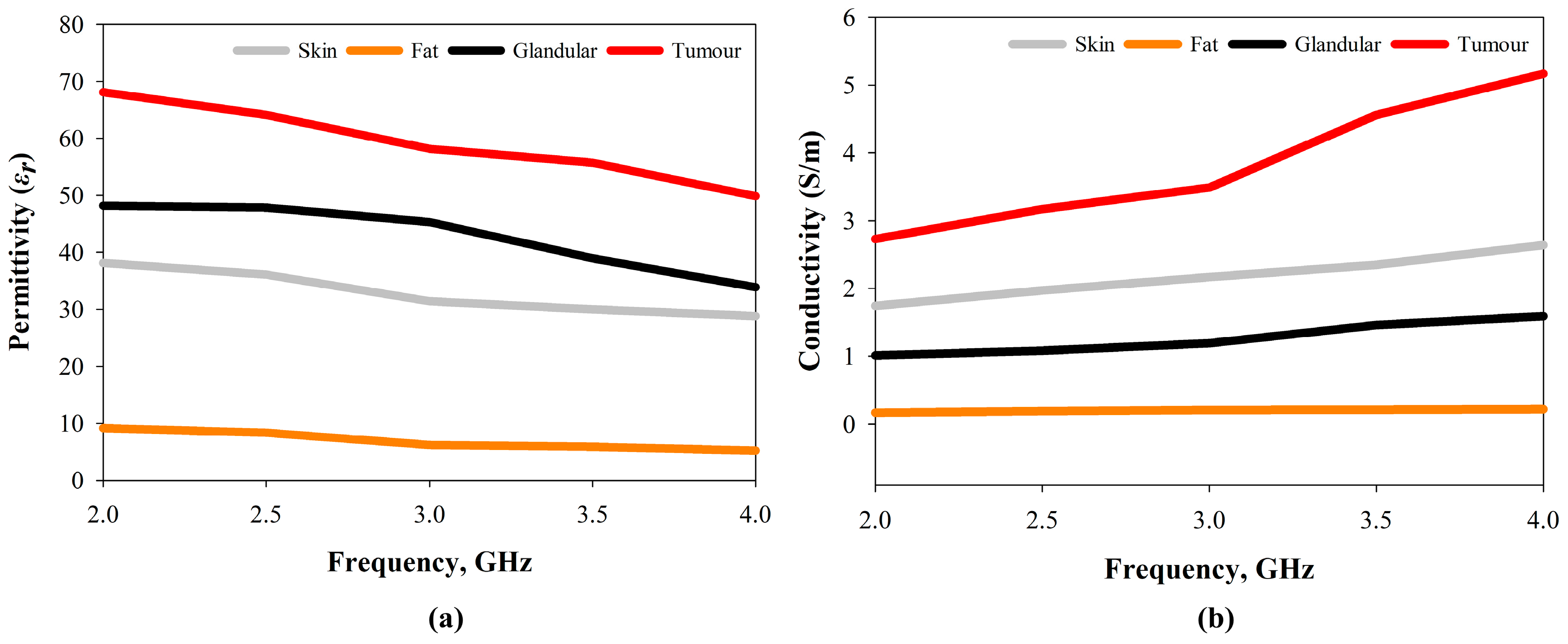
| [47,48] | 5 | 0.1 | 38 | 1.8 | 47 | 2.1 | 67 | 3.1 |
| Materials | Quantity | |||
|---|---|---|---|---|
| Skin | Fat | Glandular | Cancer | |
| Distilled water | 80 mL | 40 mL | 80 mL | 100 mL |
| Propylene glycol | 7 mL | 2 mL | 7 mL | 6.5 mL |
| 200 Bloom calf-skin gelatine | 5.88 g | 7 g | 5 g | 9 g |
| Safflower Oil | 14 mL | 39 mL | 21 mL | 7 mL |
| Formalin (37% formaldehyde solution) | 0.30 mL | 0.30 mL | 0.30 mL | 0.30 mL |
| Surfactant | 0.30 mL | 0.30 mL | 0.30 mL | 0.30 mL |
| Xanthan gum | 1.3 g | 1.3 g | 1.3 g | 1.3 g |
Publisher’s Note: MDPI stays neutral with regard to jurisdictional claims in published maps and institutional affiliations. |
© 2022 by the authors. Licensee MDPI, Basel, Switzerland. This article is an open access article distributed under the terms and conditions of the Creative Commons Attribution (CC BY) license (https://creativecommons.org/licenses/by/4.0/).
Share and Cite
Hossain, K.; Sabapathy, T.; Jusoh, M.; Lee, S.-H.; Rahman, K.S.A.; Kamarudin, M.R. Negative Index Metamaterial-Based Frequency-Reconfigurable Textile CPW Antenna for Microwave Imaging of Breast Cancer. Sensors 2022, 22, 1626. https://0-doi-org.brum.beds.ac.uk/10.3390/s22041626
Hossain K, Sabapathy T, Jusoh M, Lee S-H, Rahman KSA, Kamarudin MR. Negative Index Metamaterial-Based Frequency-Reconfigurable Textile CPW Antenna for Microwave Imaging of Breast Cancer. Sensors. 2022; 22(4):1626. https://0-doi-org.brum.beds.ac.uk/10.3390/s22041626
Chicago/Turabian StyleHossain, Kabir, Thennarasan Sabapathy, Muzammil Jusoh, Shen-Han Lee, Khairul Shakir Ab Rahman, and Muhammad Ramlee Kamarudin. 2022. "Negative Index Metamaterial-Based Frequency-Reconfigurable Textile CPW Antenna for Microwave Imaging of Breast Cancer" Sensors 22, no. 4: 1626. https://0-doi-org.brum.beds.ac.uk/10.3390/s22041626