
Miniaturized Bandpass Filter Using a Combination of T–Shaped Folded SIR Short Loaded Stubs


1
Medical Devices R&D Center, Gachon University Gil Medical Center, 21, 774 Beon-gil, Namdong-daero, Namdong-gu, Incheon 21565, Korea
2
Department of Biomedical Engineering, College of Medicine, Gachon University, 38-13, 3 Beon-gil, Dokjom-ro 3, Namdong-gu, Incheon 21565, Korea
3
Department of Biomedical Engineering, College of Health Science, Gachon University, 191 Hambak-moero, Yeonsu-gu, Incheon 21936, Korea
4
Department of Health Sciences and Technology, Gachon Advanced Institute for Health Sciences and Technology (GAIHST), Gachon University, 38-13, 3 Beon-gil, Dokjom-ro, Namdong-gu, Incheon 21565, Korea
5
Department of Electronic Engineering, Gyeonggi University of Science and Technology, 269 Gyeonggigwagi-daero, Siheung 15073, Korea
*
Author to whom correspondence should be addressed.
†
These authors contributed equally to this work.
Sensors 2022, 22(7), 2708; https://0-doi-org.brum.beds.ac.uk/10.3390/s22072708
Submission received: 25 February 2022
/
Revised: 25 March 2022
/
Accepted: 27 March 2022
/
Published: 1 April 2022
(This article belongs to the Special Issue Antenna and Microwave Sensors)
Abstract
:The consumption of multimedia content is ubiquitous in modern society. This is made possible by wireless local area networks (W–LAN) or wire service systems. Bandpass filters (BPF) have become very popular as they solve certain data transmission limitations allowing users to obtain reliable access to their multimedia content. The BPFs with quarter–wavelength short stubs can achieve performance; however, these BPFs are bulky. In this article, we propose a compact BPF with a T–shaped stepped impedance resonator (SIR) transmission line and a folded SIR structure. The proposed BPF uses a T–shaped SIR connected to a J–inverter structure (transmission line); this T–shaped SIR structure is used to replace the λg/4 transmission line seen in conventional stub BPFs. In addition, a folded SIR is added to the short stubs seen in conventional stub BPFs. This approach allows us to significantly reduce the size of the BPF. The advantage of a BPF is its very small size, low insertion loss, and wide bandwidth. The overall size of the new BPF is 2.44 mm × 1.49 mm (0.068λg × 0.059λg). The proposed BPF can be mass produced using semiconductors due to its planar structure. This design has the potential to be widely used in various areas including military, medical, and industrial systems.
1. Introduction
In the era of the fourth industrial revolution, the internet of things (IoT) based on big data and artificial intelligence (AI) applications have become explosively popular [1]. The reason is that in the fourth industrial revolution, artificial intelligence learning technology is often used, and artificial intelligence learning technology operates an automation system through big data collection and processing. At this time, most of the data for big data collection has a high capacity, and broadband communication is utilized for large–capacity processing. Moreover, to increase portability, the size of the system is becoming smaller. Bandpass filters (BPFs) are an essential component in the microwave devices that are usually used in both RF front–ends and as transmission components in fourth industrial revolution systems [2]. In addition, the fourth industrial revolution, big data, autonomous driving functions, and sensors are increasingly used. In the case of a bandpass filter, it is sometimes applied as a sensor that detects a resonance phenomenon and passes a desired frequency band [3,4]. The sensor–based bandpass filter is also applied to medical systems for diagnosis or treatment [3,4]. Among BPFs, stub BPFs are known for having a simple structure and being easy to produce. In addition, a stub BPF’s bandwidth can be adjusted (narrow or wide) through the tapped line technique [5,6,7]. This has led to stub BPFs being in great demand.
Moreover, quarter–wavelength short stubs BPFs are often used instead of quarter–wavelength open stub BPFs when the vertical size of the BPF must be reduced [8,9]. On the other hand, there is not a design that can reduce the horizontal–size of the transmission line (TL) in BPFs with λg/4 short or λg/2 open stubs (18.7 mm × 18.9 mm @ 5.8 GHz and 0.45λg × 0.19λg) [5,10]. Currently, in order to reduce the size of a BPF, a high dielectric (εr) substrate is used, and the cost of this approach is very high. As such, there is great interest in designing BPFs with desirable characteristic in terms of a good response, small size, and low cost [11].
There have been numerous studies to reduce the size of stub BPFs while ensuring a wide bandwidth [12,13,14]. The authors of [12] used the zeroth–order resonance (ZOR) method producing a 11.9 mm × 6.0 mm BPF with a bandwidth of 119%. However, this BPF used a coupling structure for the feeding line, which generated coupling losses. The BPF proposed in [13] was 19.88 mm × 22.62 mm in size and had a bandwidth of 116%; the BPF used a coupling structure for its in/output part and employed the DGS (defected ground structure) technique. The disadvantages of this BPF, in addition to being quite bulky, were the coupling losses it generated and the parasitic phenomenon between the transmission line and ground that occurred. In [14], a BPF was introduced that had a wide bandwidth of 109% but was also quite large in size (23.4 mm × 10 mm). In addition, this BPF used the DGS technique. Its parasitic performance between the transmission line and ground was bad, while its insertion losses were high. Studies [15,16,17] described BPFs that were 32 mm × 10 mm, 13.0 mm × 10.0 mm, and 150 mm × 150 mm, respectively, in size and had wide bandwidths (123% [15,16] and 146% [17]). However, these devices also had high insertion losses (0.8 dB [13], 0.3 dB [14], and 0.55 dB [17]).
In this article, we present a compact BPF with λg/4 short stubs that uses a T–shaped SIR transmission line and a folded SIR structure. The T–shaped SIR transmission line and folded SIR are designed to further reduce horizontal–TL and short stubs as well as the vertical length. By replacing the series λg/4 TL and shunt λg/4 short stubs, which protrude along the respective horizontal and vertical axes, with T–shaped and folded SIRs, the proposed BPF achieves a more compact size. The compact a BPF has a simple structure and low insertion losses.
2. Analysis for Phenomenon of a BPF
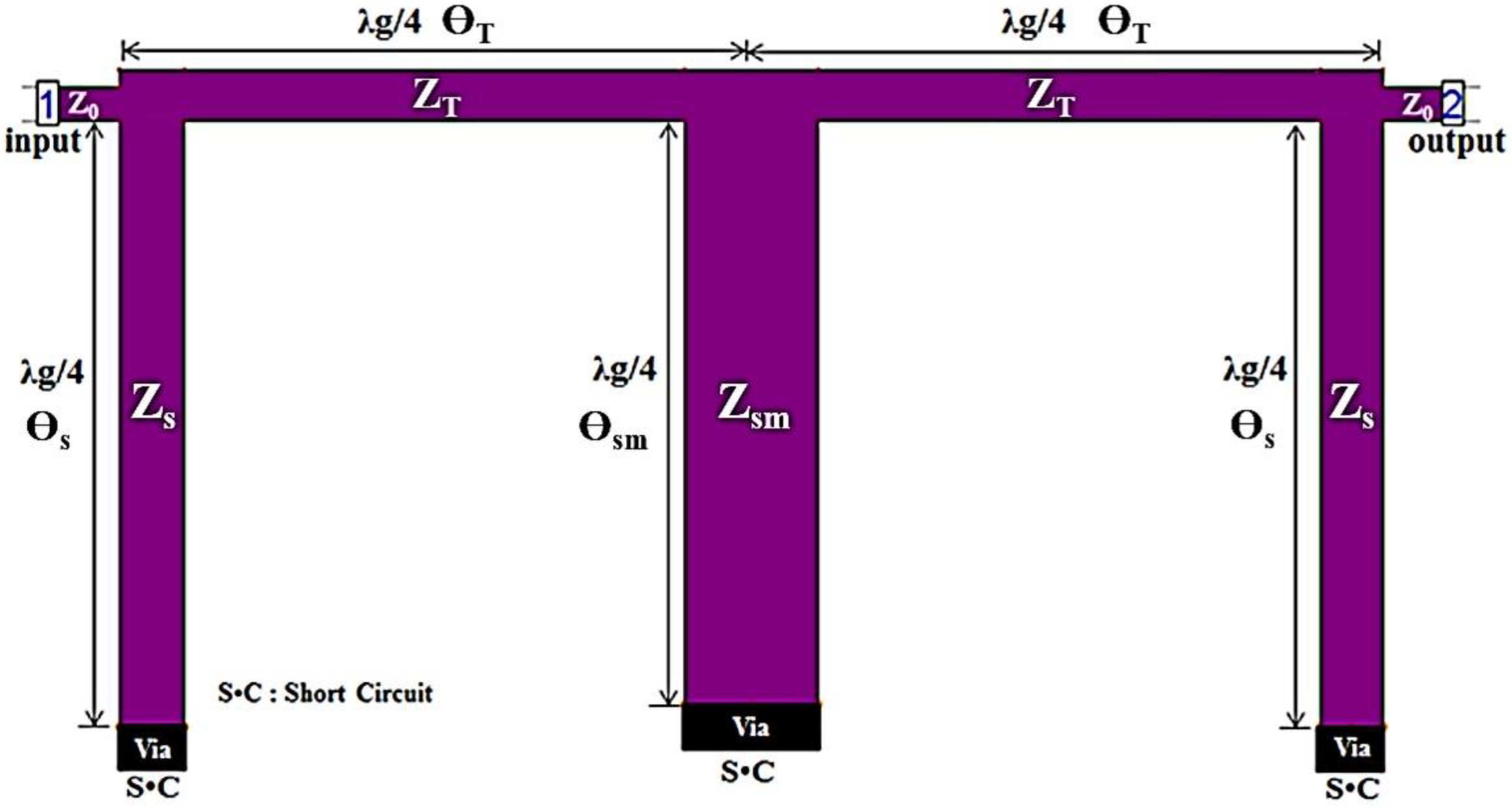
A conventional BPF with λg/4 short stubs coupled to a λg/4 transmission line (TL) and λg/4 short stubs is shown in Figure 1 [5,9]. From the figure, ZT is the characteristic impedance of a λg/4 transmission line, and the Zs and Zsm are characteristic of λg/4 short stubs, respectively. They have electrical lengths of 90 degrees. Then, the electrical parameters of a conventional BPF is provided in Table 1, in which we report the Zs, Zsm and Zt respectively. The θs, θsm and θT are the electrical lengths of the short stubs and transmission line (TL) in the conventional BPF. A transmission line is operated with the admittance impedance (J–inverter).
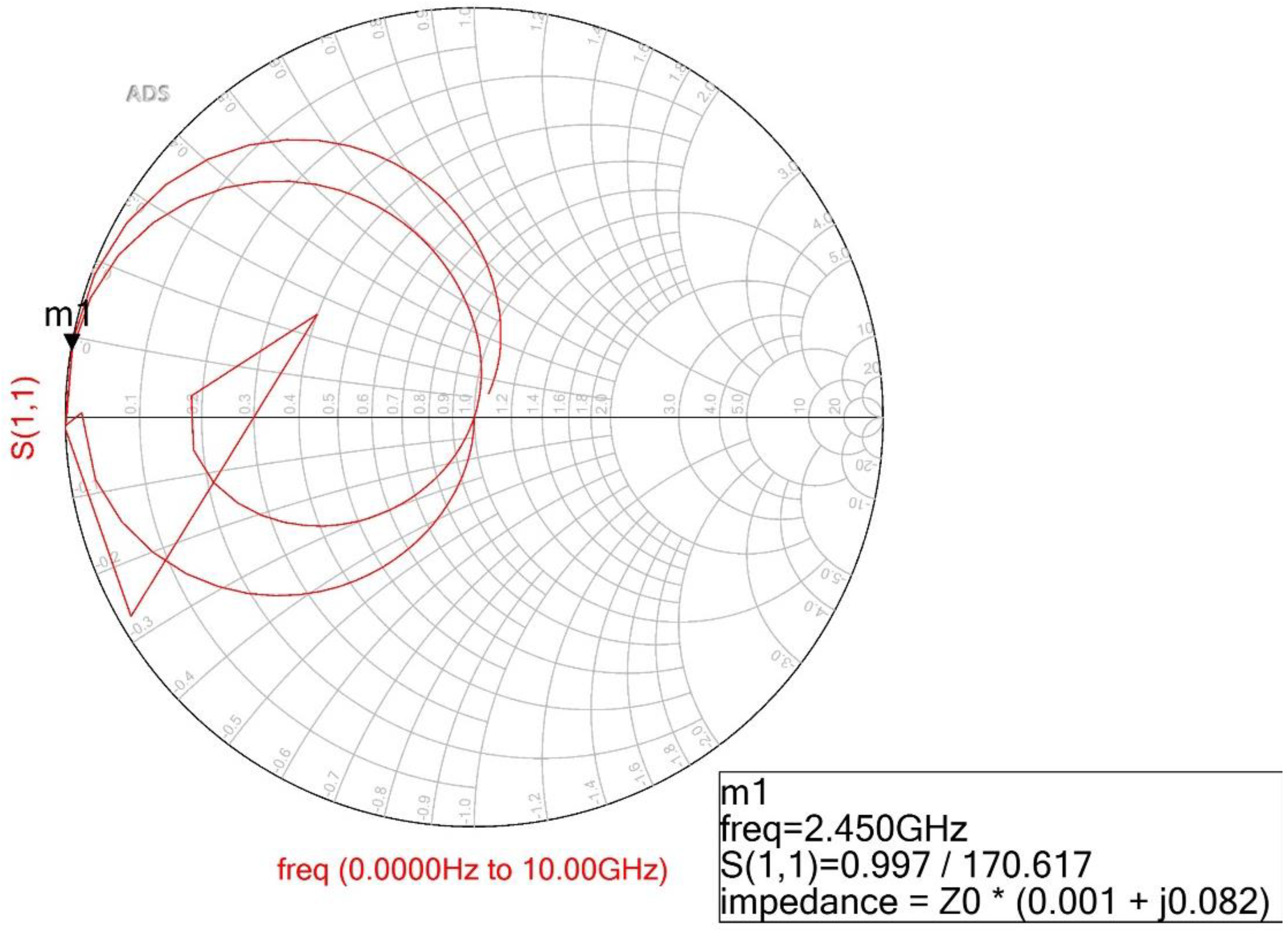
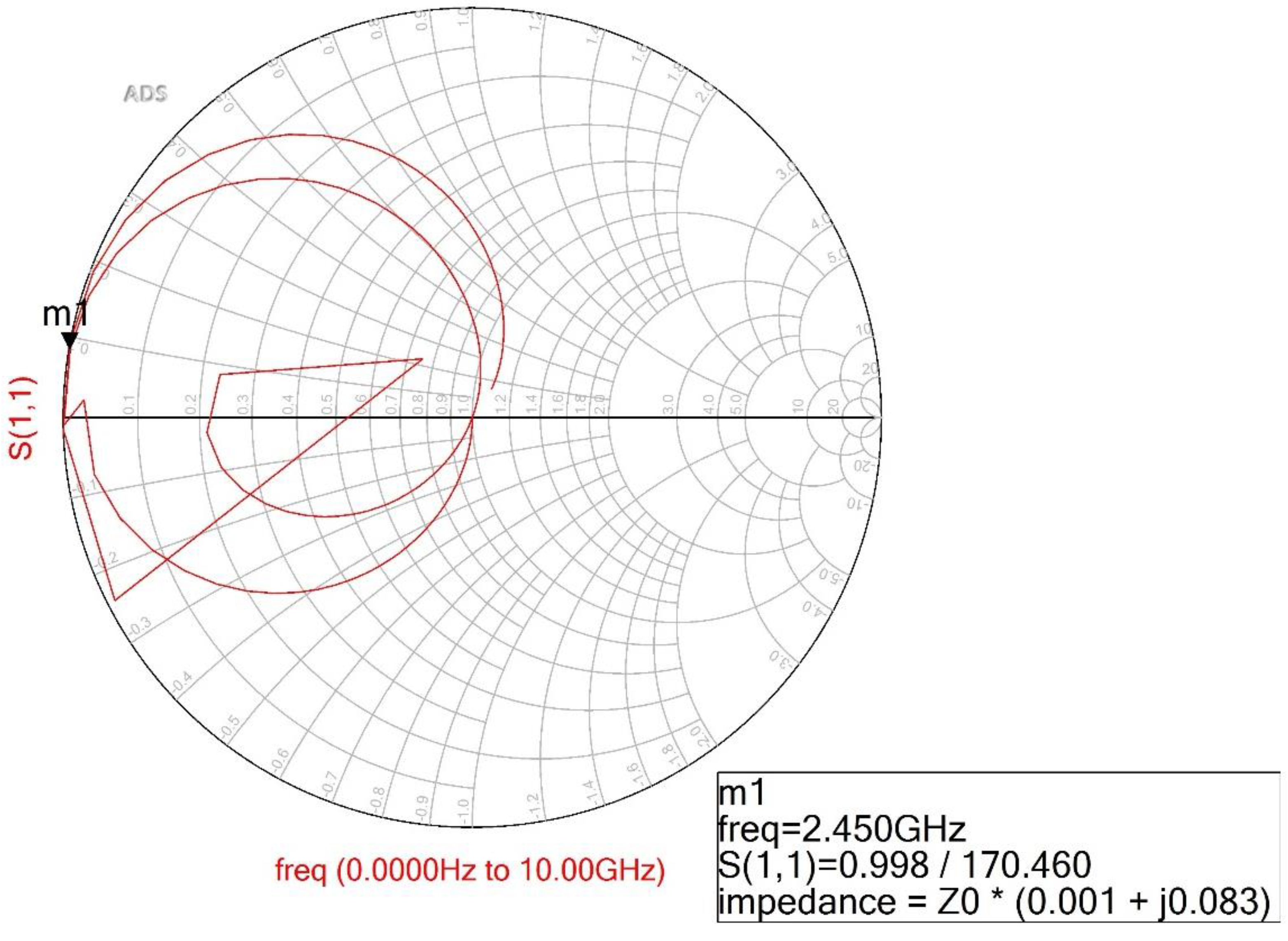
Figure 2 shows the simulation result of the Smith chart. In the figure, the real and imaginary impedance are 0.001 + j0.082 with a bandwidth of 120% at a center frequency of 2.45 GHz in the conventional BPF. However, the proposed BPF does not have the structure and conditions of a conventional BPF.
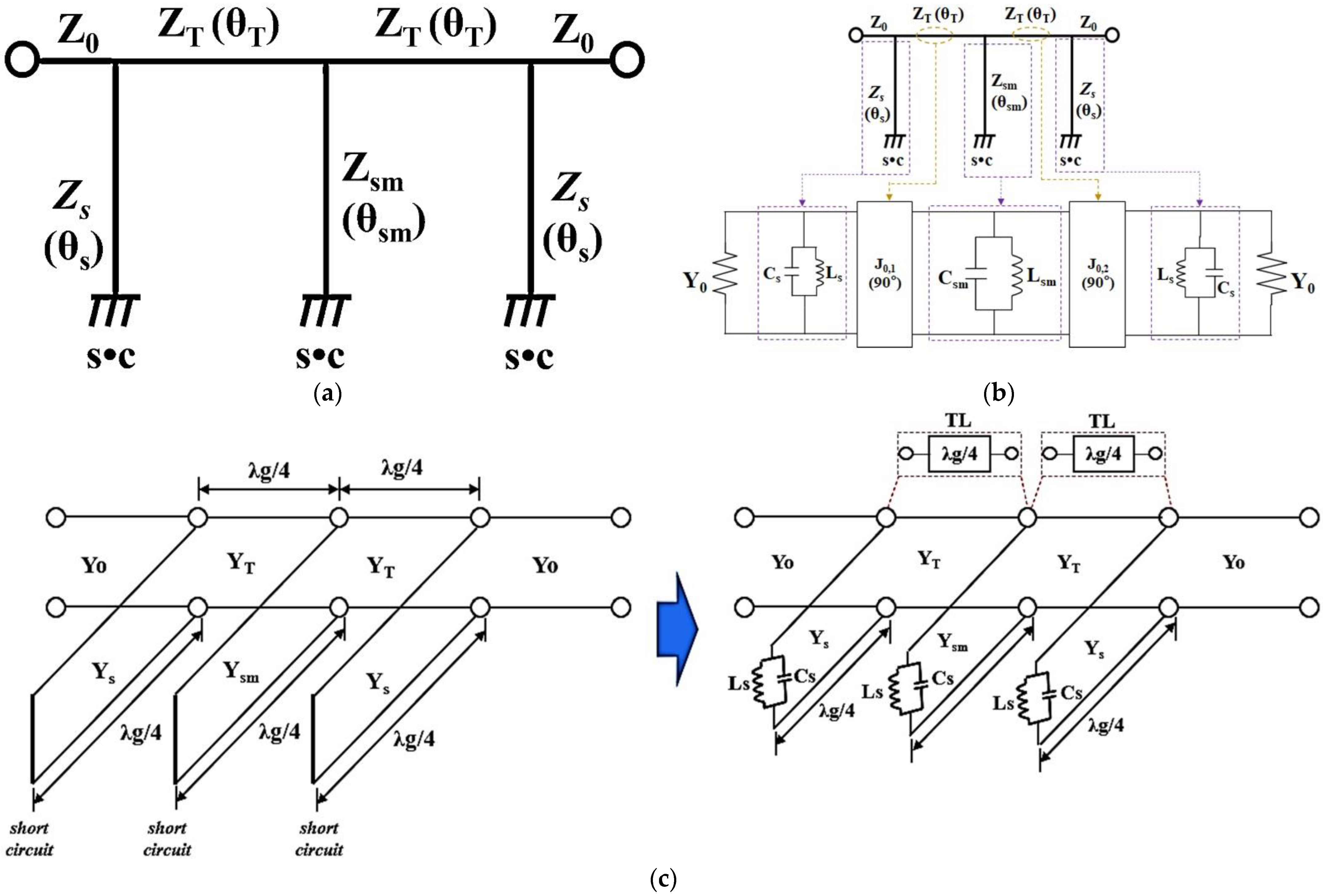
The proposed BPF is composed of a T–shaped SIR transmission line and a folded short stub, as shown in Figure 3a. In the figure, Zs and Zsm are the characteristic impedance of the folded short stubs, while ZT is the characteristic impedance of the T–shaped transmission line. As shown in the figure, θs and θsm are the electrical length of the folded short stubs, while θT is the electrical length of the T–shaped transmission line.
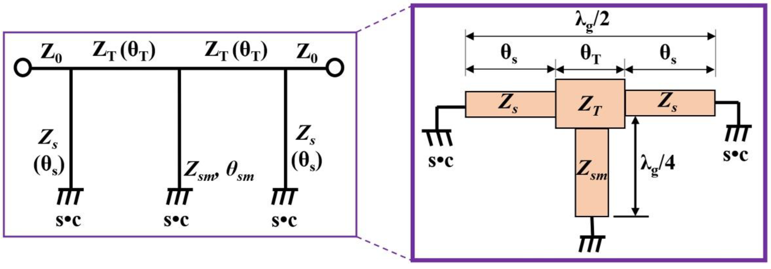
Figure 3b shows the equivalent circuit of the proposed BPF. The equivalent circuit of a proposed BPF consists of a resonant circuit (Cs//Ls and Csm//Lsm) and J–inverter (J0,1 and 0,2); the resonant circuit is connected to the inductors (Ls and Lsm) and capacitors (Cs and Csm) in the short–circuited shunt stubs with λg/4, as shown in Figure 3c. The J–inverter consists of a λg/4 transmission line [5,9]. Ls and Cs are the respective inductance and capacitance corresponding to the short stub Zs, while the Lsm and Csm are the inductance and capacitance corresponding to the stub (Zsm). In Figure 3c, the J–inverter is configured with the λg/4 transmission line (TL), which has a phase response of 90 degrees. In addition, the shunted short stubs are configured with the inductance (Ls and Lsm) and capacitance (Cs and Csm) resonant circuits. Then, the short stubs with the inductance and capacitance resonant circuits have a phase response of 90 degrees. Here, the Yo is the characteristic admittance, and the Ys and Ysm are characteristic of admittance for short stubs. YT is characteristic of the admittance of the transmission line. Figure 4 shows the SIR structure; the Zs and Zsm are both high impedance SIR, while ZT is a low impedance SIR, the input impedance (Zi) values are given by Equations (1) and (2) [18,19], where Yi is the input admittance.
The SIR can be obtained from the response of the electrical length corresponding to the short–loaded stub type, which is shown in Equation (3).
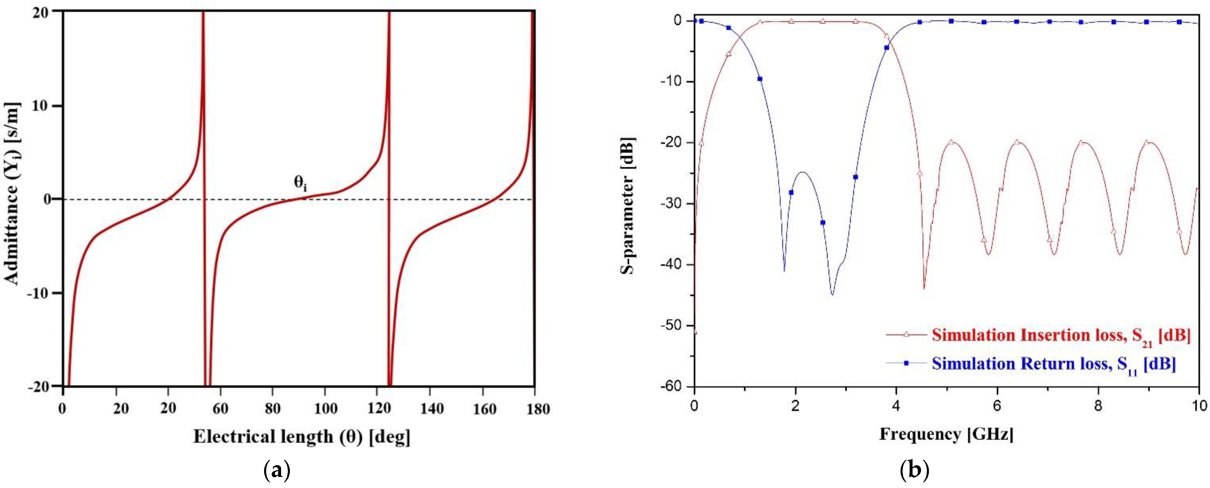
When a resonant phenomenon occurs, such as those shown in Figure 3a and Figure 4, Yi becomes zero (Yi = 0). Then, at the resonant frequency, the electrical length and impedance matching must be zero (θi = 90°) at Zi = ZT/Zs,sm. where Zi is the input impedance. The calculated impedance and electrical length for the equivalent circuit are given in Table 2. Then, the real and imaginary impedance of the proposed BPF are 0.001 + j0.083 with a phase response of 90 degrees at 2.45 GHz, as shown in Figure 5, which is similar to Figure 2 (0.001 + j0.082) with a phase response of 90 degrees at 2.45 GHz.
Figure 6 shows the simulation results for the equivalent circuit of a BPF. From the figure, the filter shows the simulated frequency is 2.45 GHz (0.94 to 3.88 GHz) with a bandwidth of 120%, and the insertion and return losses are 0.09 dB and 24.8 dB, respectively.
3. Design and Fabrication
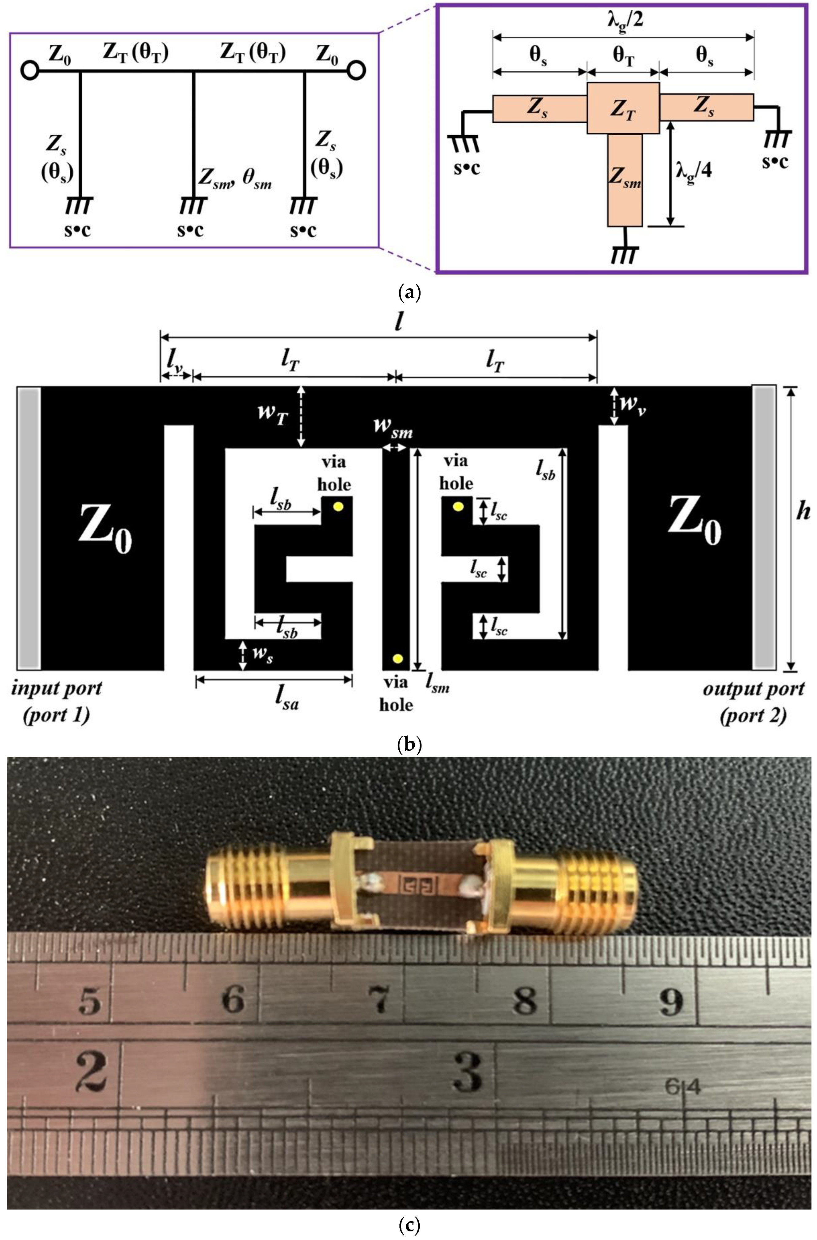
The structure of a proposed BPF has a T–shaped SIR transmission line and folded SIR short stubs whose size can be reduced as shown in Figure 7a. This figure shows how the folded SIR structure (Zs and Zsm), which has high impedance (short circuit loaded), and the T–shaped SIR structure (ZT), which has low impedance (middle term), are applied to the short stubs and transmission line (J–inverter).
Figure 7b shows the design of the proposed BPF. Here, it is shown that lsa, lsb, and lsc are 0.51 mm, 0.19 mm and 0.14 mm, respectively, while lsm, lT, and lv are 1.17 mm, 0.99 mm and 0.16 mm, respectively. ws, wsm, wT and wv are 0.16 mm, 0.14 mm, 0.32 mm and 0.20 mm, respectively, while l × h are 2.44 × 1.49 mm2. In addition, the via hole has a diameter of Ø0.3 mm. The lv structure gives extra space between the folded SIR short stub and feeding line. If the lv was not between them, the folded SIR short stubs and feeding line could become connected, and there would be a danger of a short circuit. As such, the physical length of lv should be within λg/8.
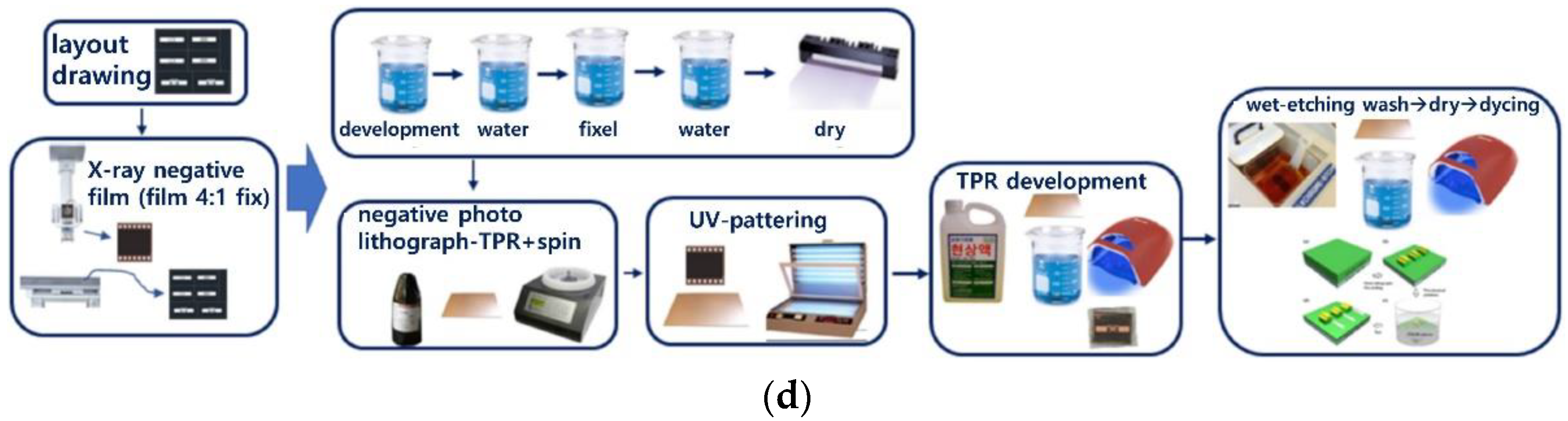
Figure 7c shows the proposed BPF fabricated on a Teflon substrate that has a low dielectric constant of 2.54 and a height of 0.54 mm. In the fabrication process, the film is developed through development, water, fixer, and drying processes through X–ray imaging, as shown in Figure 7d, to manufacture the filter. The substrate is put on the spin quarter, the photo resistor (TPR) solution is applied, and the spin operation is performed. Then, after UV–patterning of the substrate and film, the TPR solution is sacrificed using TPR development. Finally, the production of the filter is completed through wet etching [20].
4. Experimental Results
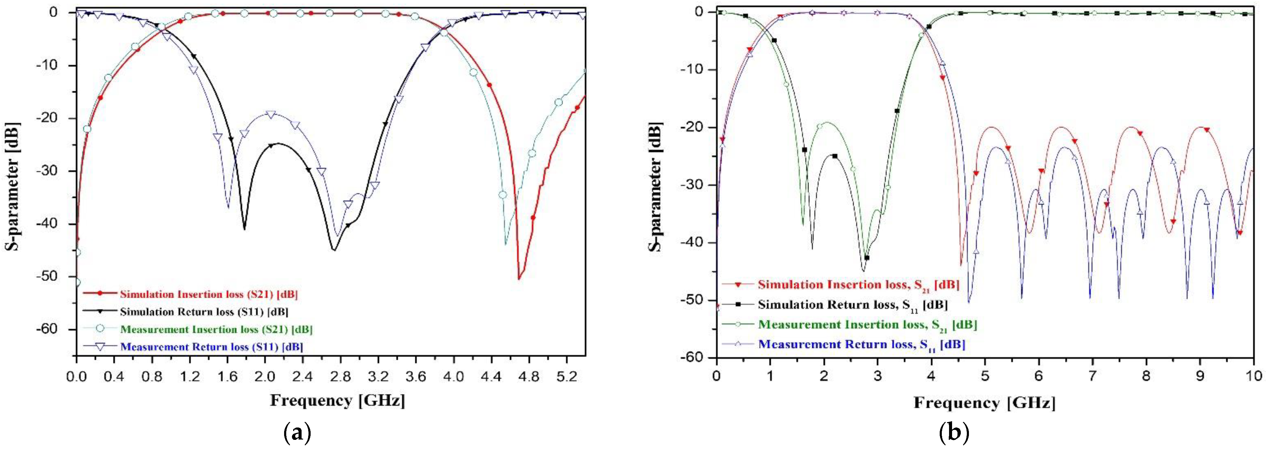
The results from the simulations and experiments on the proposed BPF with a T–shaped SIR transmission line and folded SIR short stubs are shown in Figure 8. As seen in the figure, the filter through simulation gave insertion and return losses of 0.10 dB and 24.9 dB, respectively, and a bandwidth of 120% at a center frequency of 2.45 GHz (0.94 to 3.88 GHz band), the experiment gave insertion and return losses of 0.10 dB and 19.2 dB, respectively, with a bandwidth of 120% at a center frequency of 2.44 GHz (0.85 to 3.85 GHz band).
Table 3 compares the proposed BPF with others. The comparison includes details on the devices’ bandwidth, insertion loss, and total size.
In the size comparison process, [21,22,23,24,25,26] had higher frequency and permittivity values than the proposed filter. Nevertheless, the size of the proposed filter was analyzed to be smaller than [21,22,23,24,25,26]. Therefore, the small size of the proposed filter is very meaningful.
The center frequency and fractional bandwidth of the designed BPF were 2.45 GHz and 120%, respectively, which was applied to a 4G long–term evolution (LTE) mobile system. The operated frequency and bandwidth of a 4G LTE mobile system is 4 GHz (2 to 8 GHz) and 120%. However, the frequency of the proposed BPF is 2.45 GHz because the 2.45 GHz is an unlicensed frequency band. The designed filter offers suggestions for size and bandwidth tunability. Therefore, the filter used unlicensed frequencies [27].
5. Conclusions
We proposed a compact bandpass filter (BPF) with a T–shaped stepped impedance resonator (SIR) transmission line and folded SIR short stubs. The proposed BPF adopted a T–shaped SIR transmission line and folded SIR short stubs instead of the λg/4 transmission line and quarter–wavelength short stubs found in conventional stub BPFs. The advantages of this BPF are its small size, low insertion losses, and wide bandwidth.
As conventional stub BPFs are relatively large, the filter design’s compact size makes it an important step forward for BPFs. The BPF applies the SIR technique, which makes it possible to reduce the device’s size while maintaining excellent performance. The BPF can be increased in fractional bandwidth. The overall size of the proposed design is 2.44 × 1.49 mm2 (0.068λg × 0.059λg), a significant improvement over the current design. In addition, the proposed BPF can easily be mass produced thorough the use of semiconductors due to its planar structure. The design of a filter has a potential to be applied in a variety of situations including military, medical, and industrial systems.
Author Contributions
Design and experiment: K.Y., analysis and fabrication: T.-H.L., guidance and supervisor: K.G.K. All authors have read and agreed to the published version of the manuscript.
Funding
This research was supported by the MSIT (Ministry of Science and ICT), Korea, under the ITRC (Information Technology Research Center) support program (IITP–2021–2017–0–01630) supervised by the IITP (Institute for Information & communications Technology Promotion), and by the GRRC program of the Gyeonggi province (No. GRRC–Gachon2020(B01), respectively. In addition, the research was supported by the G–ABC FRD2019–11–02(3).
Institutional Review Board Statement
Not applicable.
Informed Consent Statement
Not applicable.
Data Availability Statement
The data presented in this study are available upon request from the corresponding author. The data are not publicly available because of privacy and ethical restrictions.
Conflicts of Interest
The authors declare no conflict of interest.
References
- Tambare, P.; Meshram, C.; Lee, C.C.; Ramteke, R.J. Performance Measurement System and Quality Management in Data-Driven Industry 4.0: A Review. Sensors 2022, 22, 224. [Google Scholar] [CrossRef] [PubMed]
- Manjula, J.; Malarvizhi, S. Performance Analysis of Active Inductor Based Tunable Band Pass Filter for Multiband RF Front end. Int. J. Eng. Technol. (IJET) 2013, 5, 2930–2938. [Google Scholar]
- Abdolrazzaghi, M.; Daneshmand, M.; Lyer, A.K. Strongly enhanced sensitivity in planar microwave sensors based on metamaterial coupling. IEEE Trans. Microw. Theory Tech. 2018, 66, 1843–1855. [Google Scholar] [CrossRef] [Green Version]
- Kazemi, N.; Abdolrazzaghi, M.; Musilek, P. Comparative analysis of machine learning techniques for temperature compensation in microwave sensors. IEEE Trans. Microw. Theory Tech. 2021, 69, 4223–4236. [Google Scholar] [CrossRef]
- Yoon, K.C.; Lee, J.C. Design of a 5.8 GHz narrow band-pass filter with second harmonic suppression using the open stubs. Microw. Opt. Technol. Lett. 2008, 50, 1763–1766. [Google Scholar] [CrossRef]
- Yoon, K.C.; Lee, T.H.; Kim, C.S.; Shin, K.S.; Son, K.C.; Kim, S.C. Compact size of the UWB BPF using π-type meander structure and folding short stubs. Microw. Opt. Technol. Lett. 2018, 60, 2642–2647. [Google Scholar] [CrossRef]
- Yun, T.S.; Yoon, Y.K.; Lee, B.; Choi, J.J.; Kim, J.Y.; Lee, J.C. Analysis and design of stub bandpass filters using tapped-line geometry. Microw. Opt. Technol. Lett. 2009, 51, 2338–2341. [Google Scholar] [CrossRef]
- Zhang, D.; Zhang, K.; Wu, Q.; Jiang, T. A compact wideband filter based on spoof surface plasmon polaritons with a wide upper rejection band. IEEE Photonics Technol. Lett. 2020, 32, 1511–1514. [Google Scholar] [CrossRef]
- Hong, J.S.; Lancaster, M.J. Microstrip Filter for RF/Microwave Applications; John Wiley & Sons: Hoboken, NJ, USA, 2001. [Google Scholar]
- Wei, F.; Yu, J.H.; Zhang, C.Y.; Zeng, C.; Shi, X.W. Compact balanced dual-band BPFs based on short and open stub loaded resonators with wide common–mode suppression. IEEE Trans. Circuits Syst.–II Express Briefs 2020, 67, 3043–3047. [Google Scholar] [CrossRef]
- Danaeian, M.; Zaboly, M.; Yahyazadeh, M. Ultra–compact ultra–wideband bandpass filter based on multi mode resonator concept. J. Commun. Eng. 2021, 9, 242–257. [Google Scholar]
- Upadhyay, D.K.; Kumar, U.; Mishra, G.K.; Shahu, B.L. Design of a compact UWB bandpass filter using via-less CRLH TL. J. Microw. Optoelectron. Electromagn. Appl. 2017, 16, 336–350. [Google Scholar] [CrossRef]
- Bai, L.; Zhuang, Y.; Zeng, Z. Compact quintuple notched-band UWB BPF with high selectivity and wide bandwidth. Int. J. Microw. Wirel. Technol. 2021, 13, 435–441. [Google Scholar] [CrossRef]
- Shome1, P.P.; Khan, T. A quintuple mode resonator based bandpass filter for ultra-wideband applications. Microsyst. Technol. 2020, 26, 2295–2304. [Google Scholar] [CrossRef]
- Zheng, X.; Pan, Y.; Jiang, T. UWB Bandpass filter with dual notched bands using T-shaped resonator and L-shaped defected microstrip structure. Micromachines 2018, 9, 2–11. [Google Scholar] [CrossRef] [Green Version]
- Gao, X.; Feng, W.; Che, W. Compact ultra-wideband bandpass filter with improved upper stopband using open/shorted stubs. IEEE Microw. Wirel. Compon. Lett. 2017, 27, 123–125. [Google Scholar] [CrossRef]
- Malherbe, J.A.G. Wideband bandpass filter with extremely wide upper stopband. IEEE Trans. Microw. Theory Tech. 2018, 66, 2822–2827. [Google Scholar]
- Firmansyah, T.; Praptodinoyo, S.; Wiryadinata, R.; Suhendar, S.; Wardoyo, S.; Alimuddin, A.; Chairunissa, C.; Alaydrus, M.; Wibisono, G.; Liang, G.Z.; et al. Dual-wideband band pass filter using folded cross-stub stepped impedance resonator. Microw. Opt. Technol. Lett. 2017, 59, 2929–2937. [Google Scholar] [CrossRef]
- Zhang, X.C.; Chen, X.; Sun, L.; Huang, Y.S.; Gao, X.F. A microstrip stepped-impedance resonator bandpass filter based on inductive coupling. Frequenz 2018, 73, 1–5. [Google Scholar] [CrossRef]
- Yoon, K.C.; Kim, K.G. Compact size of an interdigital band-pass filter with flexible bandwidth and low insertion-loss using a folded spiral and stepped impedance resonant structure. Electronics 2021, 10, 10162003. [Google Scholar] [CrossRef]
- Rabia Jebin, S.; Shalini, M.; Swetha, P.; Srilekha, D. Design of microstrip UWB bandpass filter using open-circuited resonators. Int. J. Eng. Res. Dev. 2015, 11, 1–6. [Google Scholar]
- Zhou, C.X.; Guo, P.P.; Zhou, K.; Wu, W. Not applicable. IEEE Microw. Wirel. Compon. Lett. 2017, 27, 636–638. [Google Scholar] [CrossRef]
- Lal Shahu, B.; Chattoraj, N.; Pal, S.; Kumar Upadhyay, D. A compact UWB bandpass filter using hybrid fractal shaped DGS. J. Microw. Optoelectron. Electromagn. Appl. 2017, 16, 38–49. [Google Scholar] [CrossRef] [Green Version]
- Zhang, T.; Xiao, F.; Bao, J.; Tang, X. Compact ultra-wideband bandpass filter with good selectivity. Electron. Lett. 2016, 52, 210–212. [Google Scholar] [CrossRef]
- Sheikhi, A.; Alipour, A.; Mir, A. Design and fabrication of an ultra-wide stopband compact bandpass filter. IEEE Trans. Circuits Syst.-II Express Briefs 2020, 67, 265–269. [Google Scholar] [CrossRef]
- Lu, J.; Wang, J.; Gu, H. Design of compact balanced ultra-wideband bandpass filter with half mode dumbbell DGS. Electron. Lett. 2016, 52, 731–732. [Google Scholar] [CrossRef]
- Kumar, A.; Jayawickrama, C.; Al-shidaifat, A.; Kumar, A.; Song, W.; Song, H. 2–8GHz, 1.6dB Integrated CMOS LNA Using Image network technique for 4G LTE application. Int. J. Eng. Res. Electron. Commun. Eng. 2017, 4, 191–193. [Google Scholar]
Figure 1.
Conventional BPF with λg/4 short stubs.

Figure 2.
Simulation result for real and imaginary impedances for a conventional BPF.

Figure 3.
Equivalent circuit of a proposed BPF. (a) BPF. (b) J–inverter. (c) Detailed equivalent circuit.
Figure 3.
Equivalent circuit of a proposed BPF. (a) BPF. (b) J–inverter. (c) Detailed equivalent circuit.

Figure 4.
SIR structure of the proposed BPF with transmission line and short stub.

Figure 5.
Simulation result for real and imaginary impedances for the proposed BPF.

Figure 6.
Simulation results for electrical response (a) and electrical length by admittance (b) bandwidth.
Figure 6.
Simulation results for electrical response (a) and electrical length by admittance (b) bandwidth.

Figure 7.
Structure of the proposed BPF: (a) SIR structure; (b) layout; (c) fabrication; and (d) fabrication process (wet etching).
Figure 7.
Structure of the proposed BPF: (a) SIR structure; (b) layout; (c) fabrication; and (d) fabrication process (wet etching).


Figure 8.
Experimental results for the proposed BPF: (a) narrow scale frequency band and (b) wide scale frequency band.
Figure 8.
Experimental results for the proposed BPF: (a) narrow scale frequency band and (b) wide scale frequency band.


Table 1.
Calculated electrical parameters of conventional BPF.
| Parameter | Value [Ω] | Parameter | Value [deg] |
|---|---|---|---|
| Zs | 256.1 | θs | 90.0 |
| Zsm | 148.0 | θsm | 90.0 |
| ZT | 37.30 | θT | 90.0 |
Table 2.
Calculated electrical parameters for the proposed BPF.
| Parameter | Value [Ω] | Parameter | Value [deg] |
|---|---|---|---|
| Zs | 89.2 | θs | 2.31 |
| Zsm | 142 | θsm | 2.79 |
| ZT | 75.0 | θT | 2.82 |
Table 3.
Comparison between the proposed BPF and others.
| Ref [#] | Center Frequency [GHz] | IL [dB] | RL [dB] | BW [%] | Size [λg] | Dielectric Constant |
|---|---|---|---|---|---|---|
| This work | 2.44 | 0.10 | 19.2 | 120 | 0.068 × 0.059 | 2.45 |
| [21] | 2.45 | 0.10 | 15.0 | 59 | 0.171 × 0.136 | 3.30 |
| [22] | 6.75 | 0.80 | 11.0 | 100 | 0.60 × 0.54 | 3.55 |
| [23] | 4.83 | 1.10 | 10.5 | 131 | 0.29 × 0.275 | 2.20 |
| [24] | 7.20 | 1.45 | 17.0 | 111 | 0.69 × 0.18 | 2.20 |
| [25] | 6.85 | 1.50 | 15.0 | 109 | 1.10 × 0.40 | 3.55 |
| [26] | 6.95 | 0.42 | 19.0 | 97 | 0.128 × 0.37 | 3.55 |
Publisher’s Note: MDPI stays neutral with regard to jurisdictional claims in published maps and institutional affiliations. |
© 2022 by the authors. Licensee MDPI, Basel, Switzerland. This article is an open access article distributed under the terms and conditions of the Creative Commons Attribution (CC BY) license (https://creativecommons.org/licenses/by/4.0/).
Share and Cite
MDPI and ACS Style
Yoon, K.; Kim, K.G.; Lee, T.-H. Miniaturized Bandpass Filter Using a Combination of T–Shaped Folded SIR Short Loaded Stubs. Sensors 2022, 22, 2708. https://0-doi-org.brum.beds.ac.uk/10.3390/s22072708
AMA Style
Yoon K, Kim KG, Lee T-H. Miniaturized Bandpass Filter Using a Combination of T–Shaped Folded SIR Short Loaded Stubs. Sensors. 2022; 22(7):2708. https://0-doi-org.brum.beds.ac.uk/10.3390/s22072708
Chicago/Turabian StyleYoon, Kicheol, Kwang Gi Kim, and Tae-Hyeon Lee. 2022. "Miniaturized Bandpass Filter Using a Combination of T–Shaped Folded SIR Short Loaded Stubs" Sensors 22, no. 7: 2708. https://0-doi-org.brum.beds.ac.uk/10.3390/s22072708
Note that from the first issue of 2016, this journal uses article numbers instead of page numbers. See further details here.