
Optimization of the Runner for Extremely Low Head Bidirectional Tidal Bulb Turbine

1
State Key Laboratory of Hydroscience and Engineering & Department of Thermal Engineering, Tsinghua University, Beijing 100084, China
2
Huaneng Clean Energy Research Institute, Beijing 102209, China
3
China Water Resources Beifang Investigation, Design & Research CO. LTD, Tianjin 300222, China
*
Author to whom correspondence should be addressed.
Energies 2017, 10(6), 787; https://0-doi-org.brum.beds.ac.uk/10.3390/en10060787
Submission received: 28 March 2017
/
Revised: 19 May 2017
/
Accepted: 2 June 2017
/
Published: 7 June 2017
(This article belongs to the Special Issue Marine Energy)
Abstract
:This paper presents a multi-objective optimization procedure for bidirectional bulb turbine runners which is completed using ANSYS Workbench. The optimization procedure is able to check many more geometries with less manual work. In the procedure, the initial blade shape is parameterized, the inlet and outlet angles (β1, β2), as well as the starting and ending wrap angles (θ1, θ2) for the five sections of the blade profile, are selected as design variables, and the optimization target is set to obtain the maximum of the overall efficiency for the ebb and flood turbine modes. For the flow analysis, the ANSYS CFX code, with a SST (Shear Stress Transport) k-ω turbulence model, has been used to evaluate the efficiency of the turbine. An efficient response surface model relating the design parameters and the objective functions is obtained. The optimization strategy was used to optimize a model bulb turbine runner. Model tests were carried out to validate the final designs and the design procedure. For the four-bladed turbine, the efficiency improvement is 5.5% in the ebb operation direction, and 2.9% in the flood operation direction, as well as 4.3% and 4.5% for the three-bladed turbine. Numerical simulations were then performed to analyze the pressure pulsation in the pressure and suction sides of the blade for the prototype turbine with optimal four-bladed and three-bladed runners. The results show that the runner rotational frequency (fn) is the dominant frequency of the pressure pulsations in the blades for ebb and flood turbine modes, and the gravitational effect, rather than rotor-stator interaction (RSI), plays an important role in a low head horizontal axial turbine. The amplitudes of the pressure pulsations on the blade side facing the guide vanes varies little with the water head. However, the amplitudes of the pressure pulsations on the blade side facing the diffusion tube linearly increase with the water head. These results could provide valuable insight for reducing the pressure amplitudes in the bidirectional bulb turbine.
1. Introduction
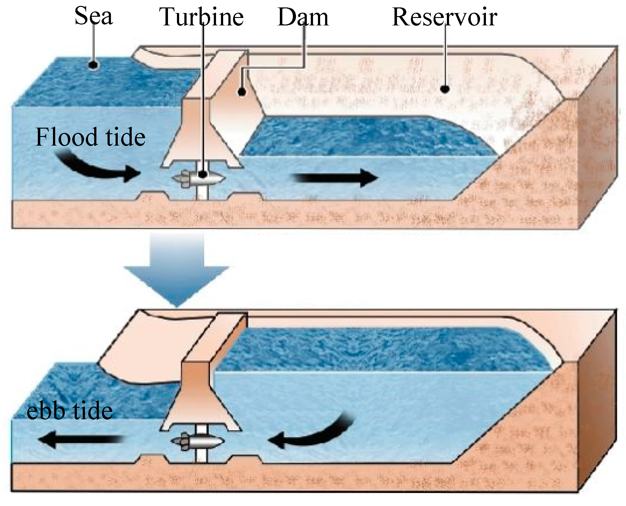
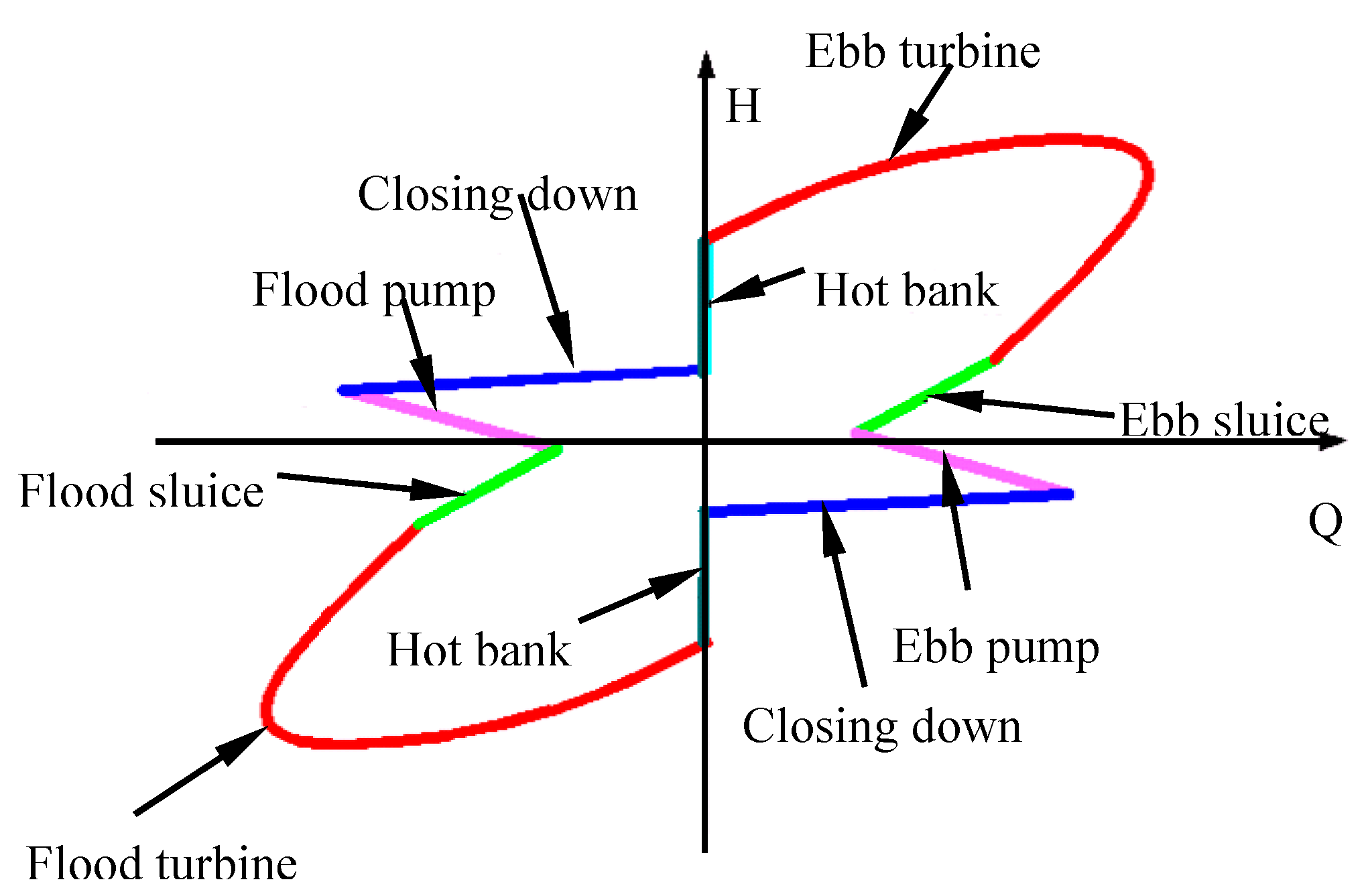
Seventy-one percent of the Earth’s surface is covered by sea with an enormous source of renewable energy, including tidal energy, marine current energy, wave energy, ocean thermal energy, and salinity gradient energy. Of which tidal energy is a form of hydroelectric generation in which the water resource is replenished by tidal movements. It is truly renewable green power and a clean source of energy without pollution. Tidal power uses the twice-daily variation in sea level caused by the gravitational effect of the moon and sun on the ocean. Tides are the daily movements with every rise and fall, storing large amounts of potential energy [1]. The tidal change in sea level can be used to generate electricity by building a dam across a coastal bay or estuary with large differences between flood and ebb tides. The flood and ebb tides allow the water to rush into, and out, of the reservoir. The flow of water generates enough power to rotate the turbines to create electricity. The generation of electricity from tides is very similar to hydroelectric generation, except that water is able to flow in both direction and, in this way, electricity can be created using bidirectional bulb tubular turbines; the operating principal of the tidal turbines are shown in Figure 1. This type of turbine could operate efficiently under extremely low water head (below 5 m) and large water head variations (0.8–5 m). The flood and ebb tides lead to multiple operating conditions, including bidirectional generating, bidirectional pumping, bidirectional sluice, etc., and frequent transitions between each operating conditions, shown in Figure 2.
Many tidal sites around the world are considered suitable for building tidal power plants; however, there are only five major tidal barrage power plants in operation so far, including La Rance [2], Kislaya Guba [3], Annapolis [4], Jiangxia [5], and Sihwa tidal power plants [6]. Of which only La Rance and the Jiangxia pilot tidal power plants use a combination of two-way generation. Aggidis and Feather [7] utilized characteristics of double regulated turbine models from Sulzer Escher Wyss of Zurich and Andritz Hydro to estimate the realistic amount of power available from tidal range generation on the Solway Firth. The bulb tubular turbine has generally been used in tidal power plants due to their extremely low water heads and the large water head variations compared with general hydraulic turbines, such as Francis and Kaplan turbines. Similar to other hydraulic turbines, the power captured by tidal generation units are mainly determined by the efficiency of the turbine runners who transfer the kinetic energy of water to mechanical energy. Many studies have focused on optimization of runners for Kaplan, Francis, pump-turbine, and unidirectional bulb turbines with large capacity using the CFD (computational fluid dynamics) method coupled with optimization algorithms. Lipej [8] presented a multi-objective genetic algorithm for the design of axial runners. Within the optimization procedure, a special program has been developed, which makes it possible to start the optimization procedure with a relatively high level of efficiency and transforms prescribed genetic parameters to the runner geometry. Yang [9] presents an automatic multi-objective hydrodynamic optimization strategy to redesign a scaled pump-turbine, and model tests were conducted to validate the final design and confirm the validity of the design strategy. Balint [10] optimized the hydrodynamics of the runner blades of an axial Kaplan turbine using the in-house software QTurbo3D. The effect of the runner blades’ geometry modification upon its hydrodynamics is shown both from energetic and cavitation points of view. Loiseau [11] optimized the shape of the blade for a large bulb turbine in the Xia Jiang project by using the latest tools in computational fluid dynamics, and a model fully homologous with the prototype was manufactured with model test results confirming the predicted ones. The increase in adaptation for the parameter design using CFD and an optimization technique to the turbine design has begun to accelerate the progress of a sophisticated and effective design technique for obtaining high-performance and reliable turbines. However, there have been few studies carried out to optimize the runner for extremely low head bidirectional tidal bulb turbines.
In this research, the CFD method coupled with an optimization algorithm is adopted to optimize the hydraulic behavior for the runner of the bidirectional tidal bulb turbines, and hydraulic performance optimum designs are successfully carried out. Then the model test results are analyzed and compared with the calculated results in both flood and ebb modes. The good agreement between experimental and simulation results is outlined. Finally, the hydraulic characteristics for the prototype turbines with optimal runners were analyzed, and the pressure pulsations in the blade surface are predicted to ensure the stable operation of the tidal units.
2. Optimization Methodology
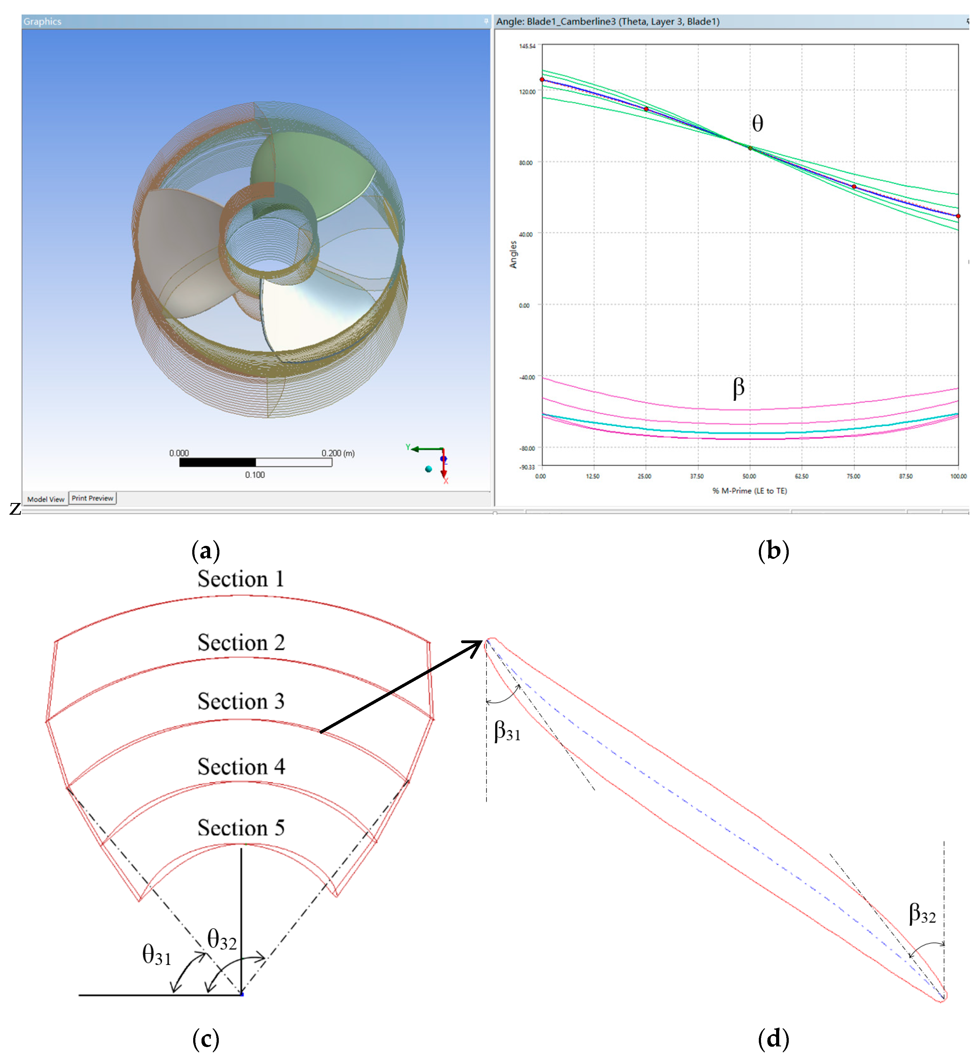
Generally, optimization processes are based on the relationships between input design parameters and output targets. In this case, the inlet and outlet angles (βj1, βj2), as well as the starting and ending of wrap angles (θj1, θj2) for the section j of the blade profile, 20 parameters in total were selected as design variables for the optimization, as shown in Figure 3. The thickness of the sections were not considered to reduce the sample number and save computational time. The target of the optimization is to obtain the maximum of the overall efficiency for the ebb and flood turbine modes. Thus, the objective function is defined in Equation (1):
where Q and H are the turbine discharge and head, n and are the rotational speed and moment acting on the runner, and and are water density and gravitational acceleration.
There are no exact functions between the design parameters and the output targets for most engineering design problems. Therefore, response surface methodology (RSM) has been employed to describe the approximate functional relations of Equation (3) by using polynomials RSM, introduced by Box and Wilson in 1951, has been a well-known method for estimating the interaction effects among independent variables without implementing factorial design experiments for each level of every independent variable [12]. A second-order model is used to fit the response surface F(Xi), which can significantly improve the optimization process when a first-order model suffers lack of fit due to interaction between variables and surface curvature. A general second-order model is defined as:
The undetermined coefficients of {a} can be found out by principle of the least square regression with the help of a set of sample points distributed in the so-called design space.
The distribution of sample points in design space has significant influence in the accuracy of estimated model, so it is necessary to choose an effective method for design of experiment (DoE). The ranges and values of each variable were chosen using Latin hypercube sampling (LHS), which is usually applied in optimization to generate a multi-dimensional distribution of parameter values for the preparation of RSM. Through LHS, the distributions of sample points in design space is equi-probable, random, and orthogonal, thus, higher accuracy of the model can be obtained with fewer sample points.
The optimization process of the runner has been completed in ANSYS Workbench in this study. According to similarity law, n11 () in the model and prototype units listed in Table 1 must remain the same. The initial model runner has a diameter of 0.35 m, with a rotational speed of 1000 r/min, and a head of 3.14 m. The variation range (±20% of the initial values) of the control parameters are given through the Design Exploration module, different combinations decided by the DoE are input to BladeModeler module and a number of runner configurations are generated, as shown in Figure 3. The design head and rotational speed keep unchanged in the optimization process. By using ANSYS CFX (ANSYS: Canonsburg, PA, USA) to calculate runner performances corresponding to different runner configurations, the RSM model between control parameters and runner performances is built to obtain (i = 0, 20), (i, j = 1, 20). Then the group of [βj1, βj2, θj1, θj2], which maximizes the target of F(Xi), was set as the final parameters of the turbine runner.
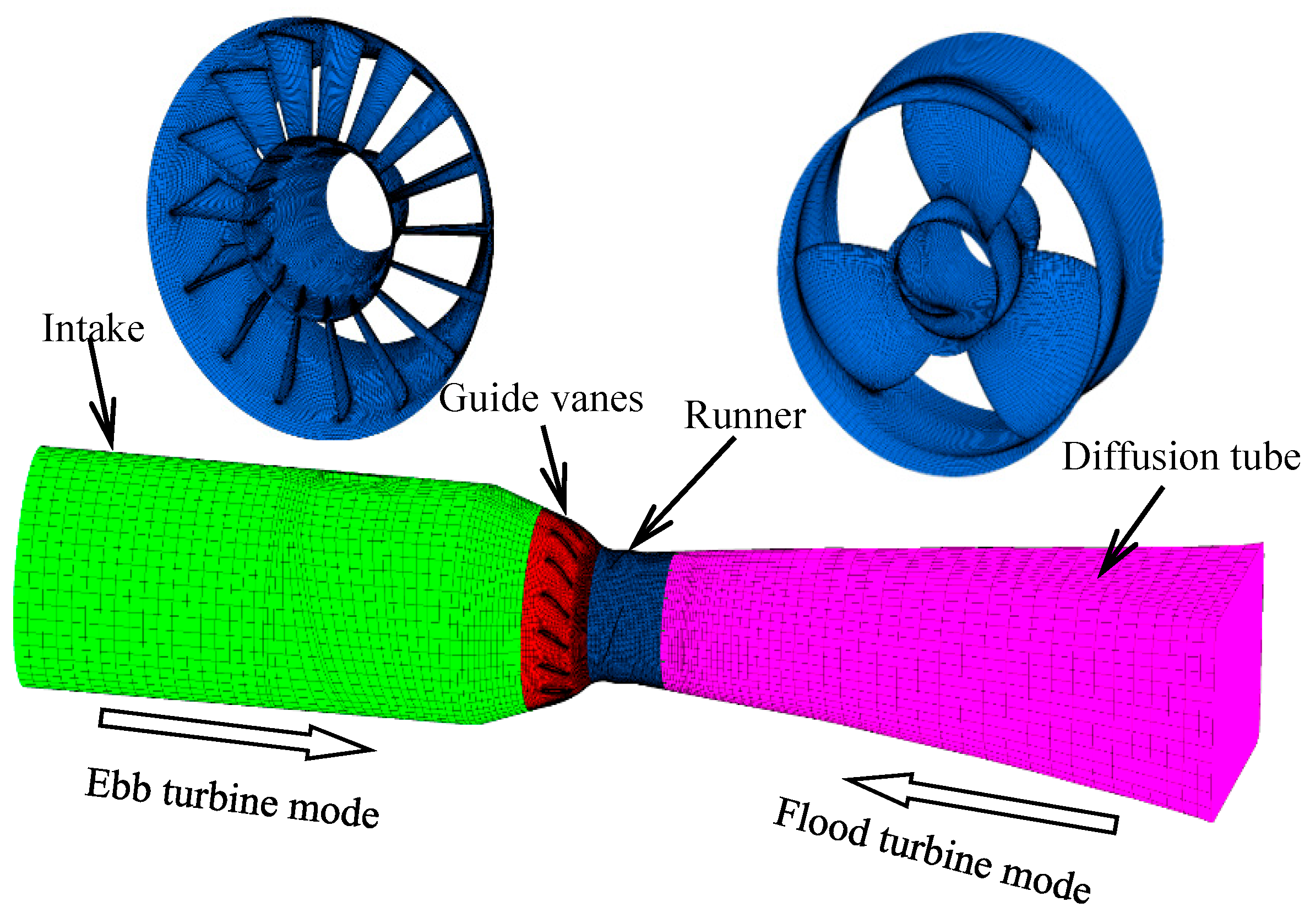
After optimization, the new runner has been imported into a 3D full-passage CFD simulation to check the final hydraulic performance. The SST k-ω turbulence model, which has been widely validated for numerical analysis of rotational machinery, is used for the turbulence closure [13]. A frozen rotor model is used for the present domain, including both stationary and rotational parts. The space discretization is based on a cell-centered finite volume scheme with the system of governing equations advanced in time using the explicit second-order scheme. The mesh sensitivity analysis has been performed to decide the mesh size used in optimization. Figure 4 presents the final mesh from the intake to the diffusion tube. The main parameters of the prototype unit are shown in Table 1.
3. Optimization Results
The initial model runner has a diameter of 0.35 m with four blades. The optimization obtained two optimal blade profiles; one runner has four blades, while the other runner has three blades. Table 2 gives a comparison of the main control parameters before and after optimization.
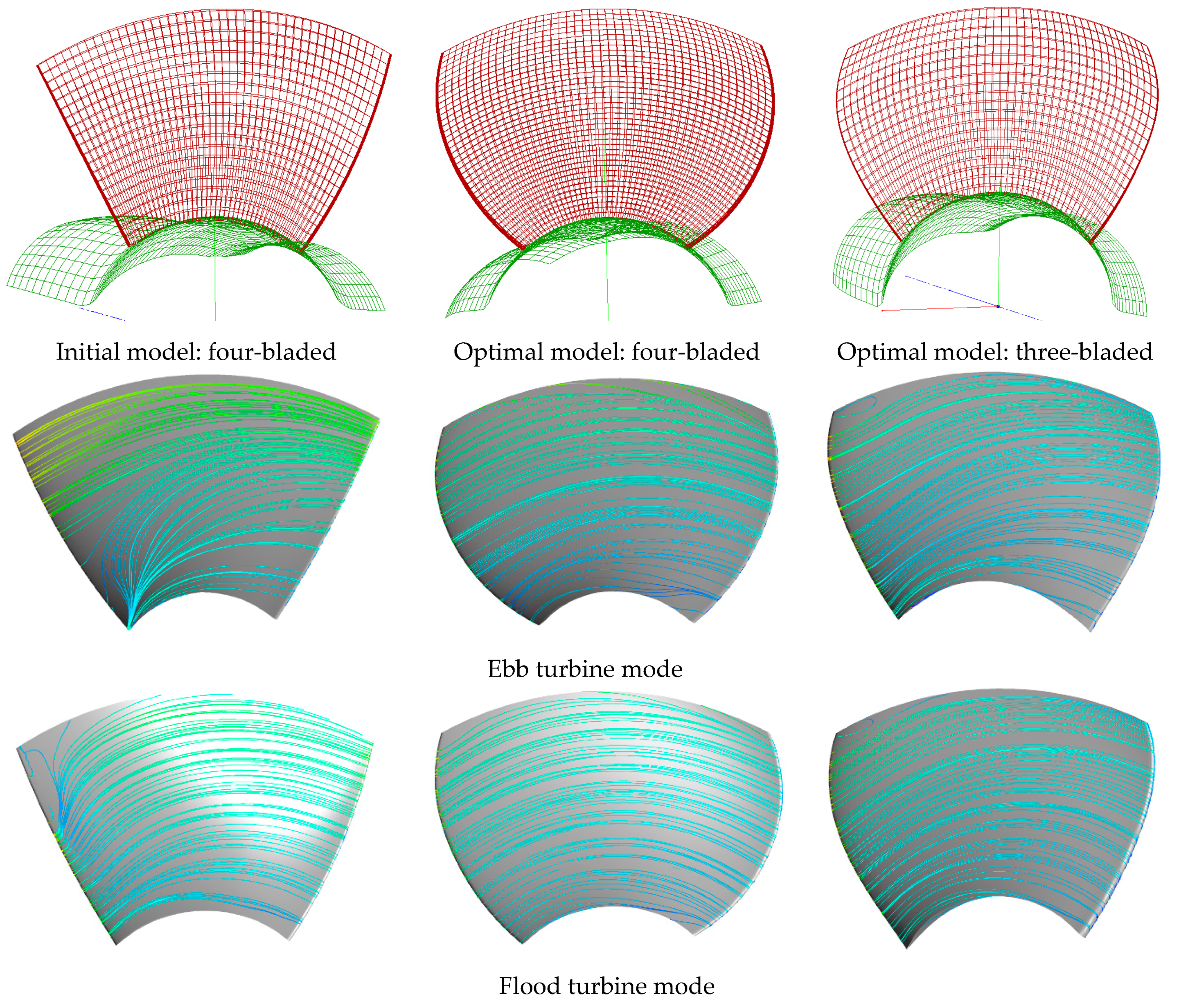
Figure 5 shows both initial and optimal blade profiles and their surface flow distribution under the optimum point. The initial model has almost straight leading and trailing edges, while the optimal runner blades have both arc leading and trailing edges, forming an “S” type at each blade profile. Thus, the streamlines on the suction side of the optimal blades are much smoother than those of the initial blade for both ebb and flood modes. However, secondary flow occurs at the suction side of the blades near the hub and shroud for the initial model.
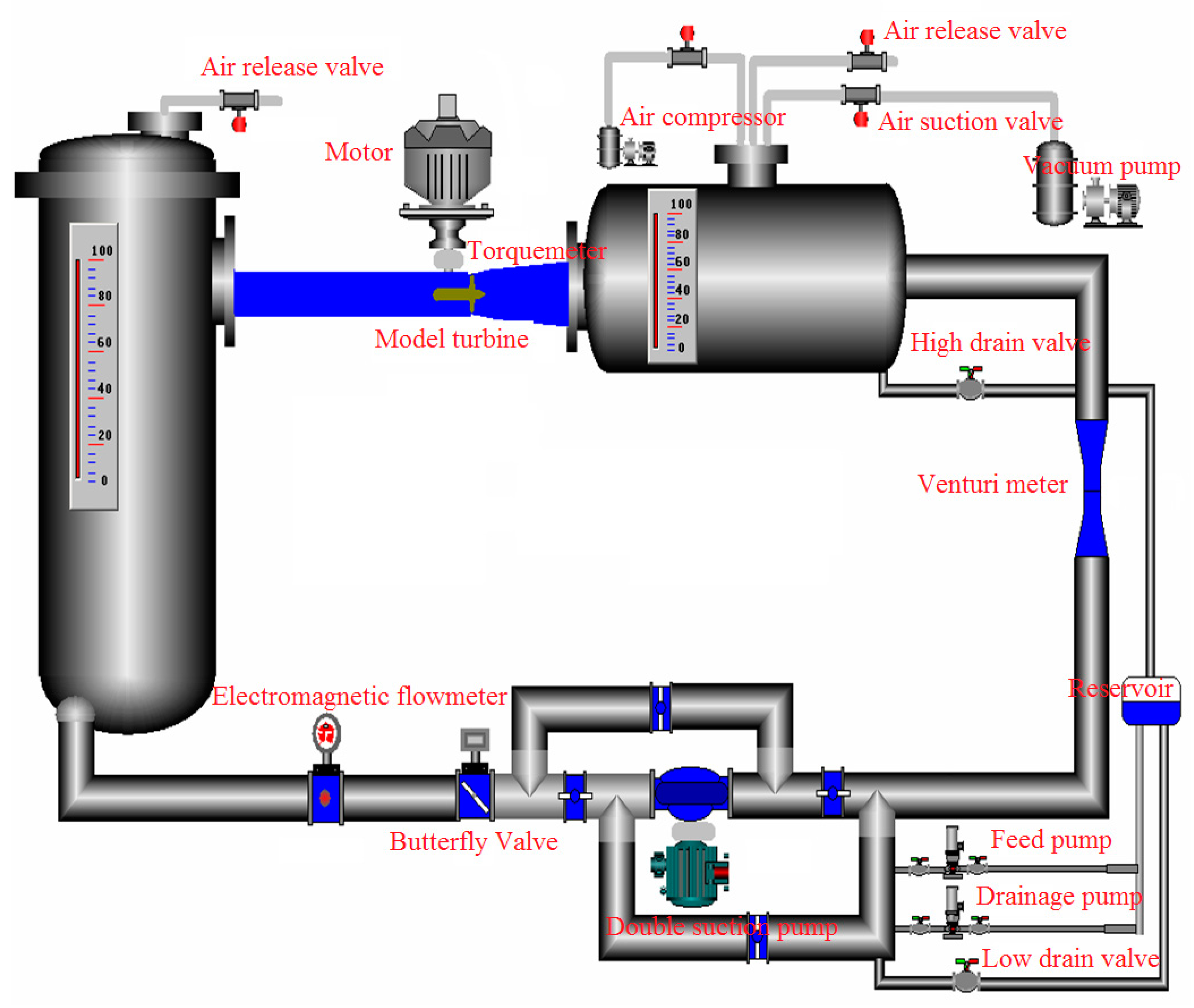
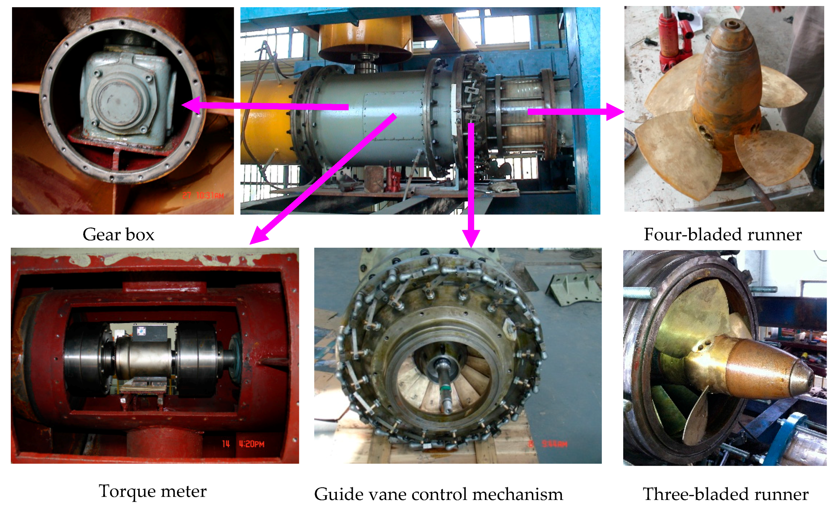
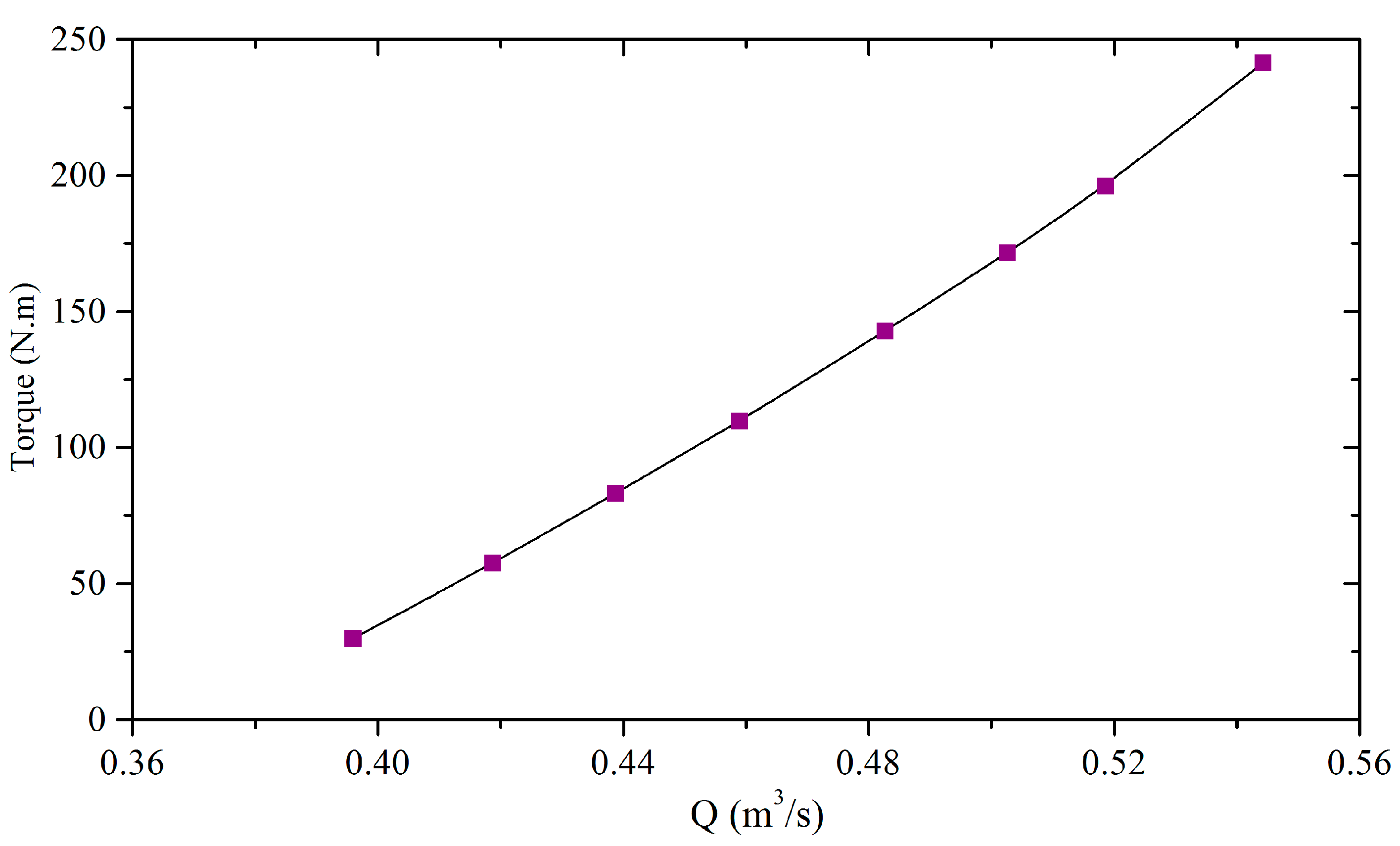
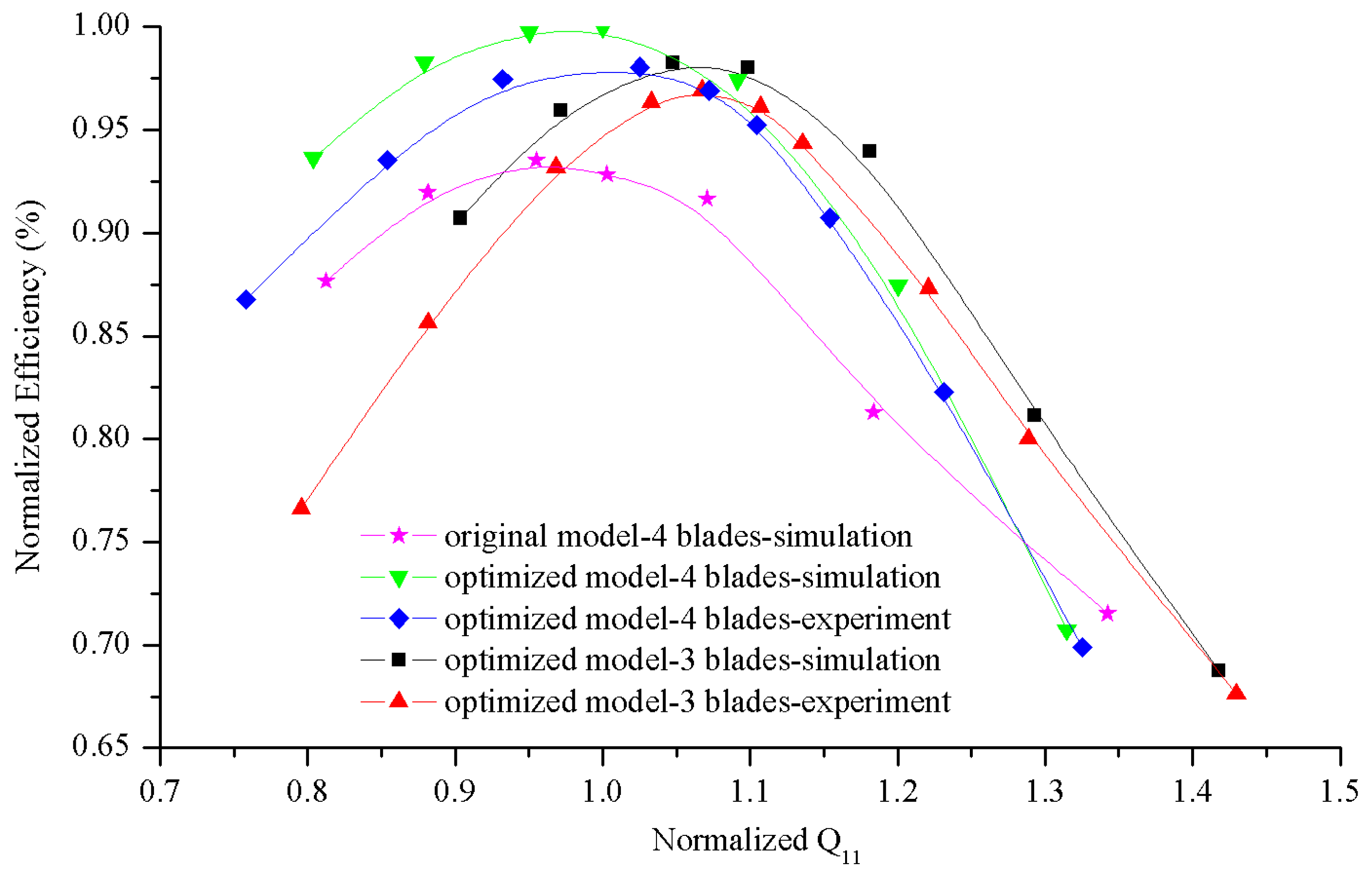
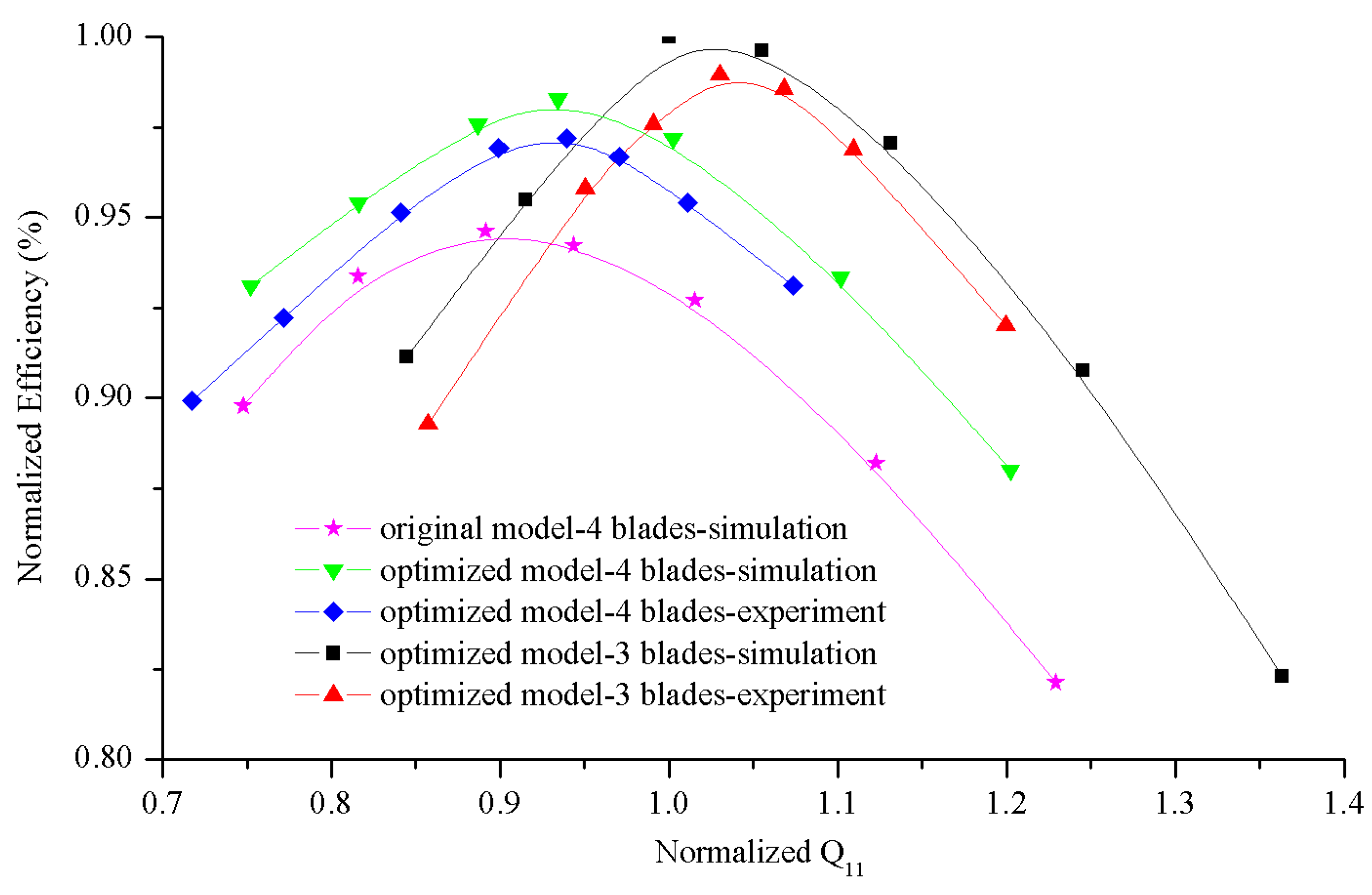
The model tests were performed on a standard hydraulic machinery test rig to verify the optimization results. The test rig fulfils the international standard IEC 60193/IEC 62006 to achieve reproducible and valid data of the test for turbines, pump turbines and pumps. It has a composition error of ±0.3% for efficiency measurement with maximum head of 30 m and maximum discharge of 1000 m3/s, as shown in Figure 6. The model turbine is shown in Figure 7 with the torque meter measuring the torque generated by the turbine, and the gear box transforms the horizontal rotation of the shaft to vertical rotation. Model tests were performed for the optimal four-bladed and three-bladed runners at the optimum blades angle and guide vanes angle. The experimental torques acting on the runner linearly increase with discharge Q for the optimal three-bladed runner, as shown in Figure 8. The experimental results were compared with the numerical results for both ebb and flood turbine modes, as shown in Figure 9 and Figure 10, where the efficiency () and unit discharge Q11 () are normalized by the maximum efficiencies and corresponding Q11. Figure 9 and Figure 10 show that the numerical simulations match well with the experimental data in terms of efficiency level and positions of the best efficiency point. The slight differences seen in the efficiency is mainly due to the fact that the small gaps at the tip and hub of the blade are ignored in the simulation. The optimal runners are much more efficient than the initial runner for both ebb and flood modes, and the best efficiency points shift from low discharge to high discharge. The best efficiency of the four-bladed runner is slightly higher than that of the three-bladed runner for the ebb mode, as show in Figure 9. On the contrary, the best efficiency of the four-bladed runner is slightly lower than that of the three-bladed runner for flood mode, as shown in Figure 10, and the best efficiency points of the three-bladed runner has a higher discharge for both ebb and flood mode.
4. Prediction of Hydraulic Characteristics for the Prototype Turbines with Optimal Runners
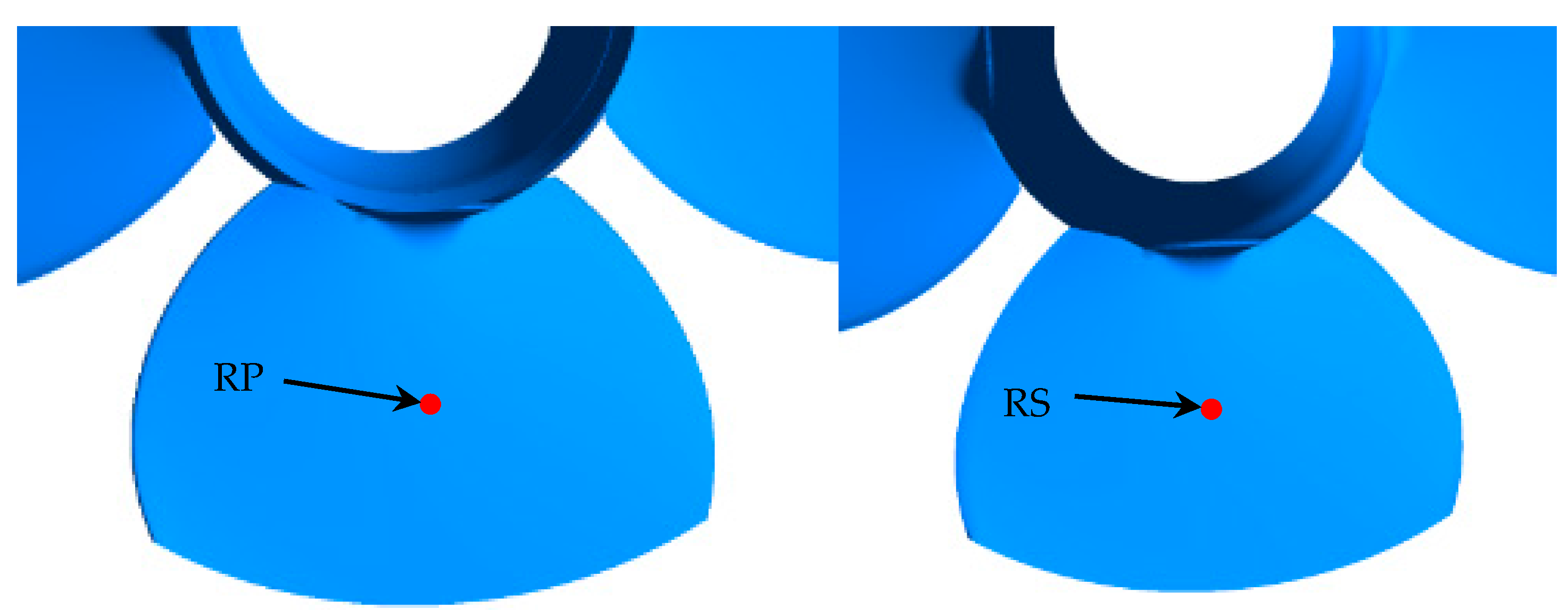
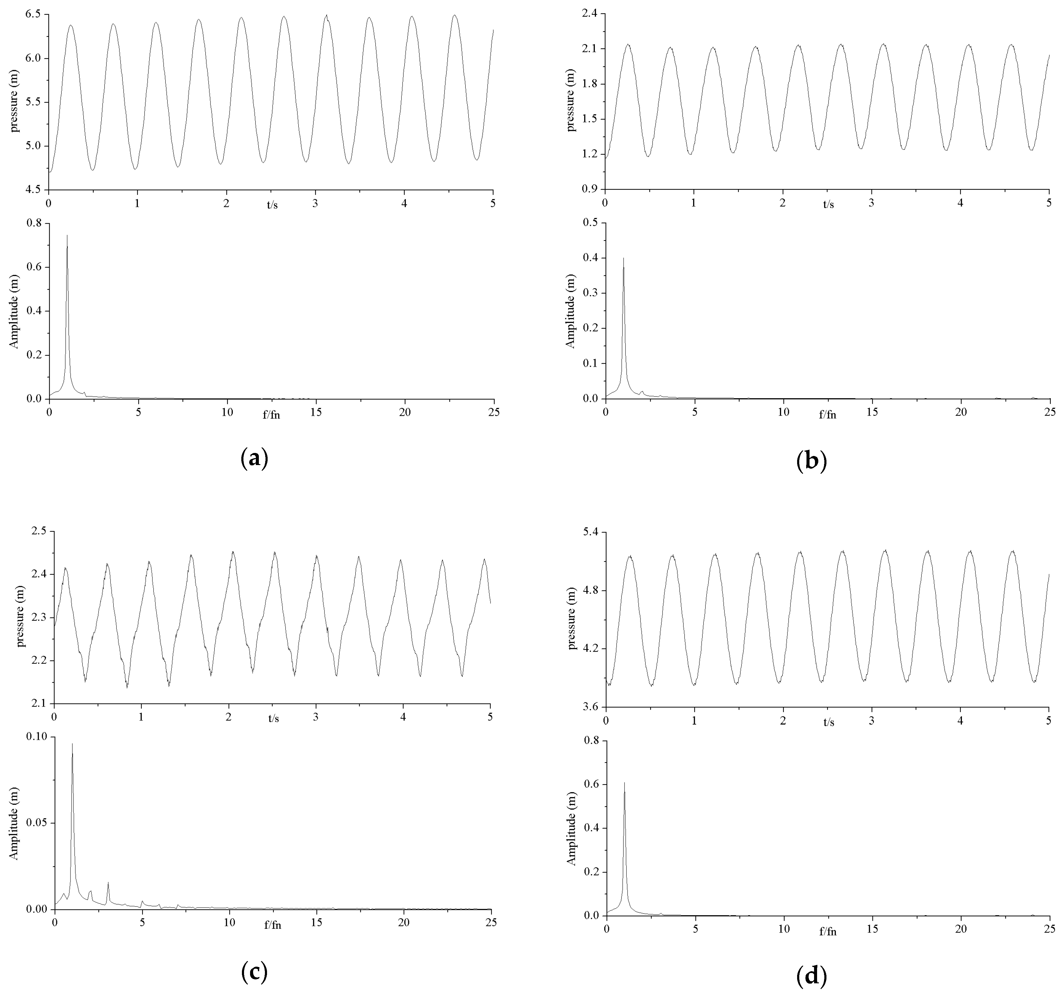
The pressure pulsation of the prototype turbines with optimal runners were then predicted using unsteady CFD analysis. In the simulations, the interfaces between the guide vanes, the runner, and the diffusion tube were modeled with a transient rotor stator with the flux transferred between neighboring zones to count for the two rotor-stator interactions. During the calculations, the pressure data were saved at the recording points on the blade surface, as shown in Figure 11, with points RP and RS rotating with the runner in the blade passage. The pressure pulsations obtained in the simulations were analyzed using FFT (fast Fourier transform) to determine the pressure pulsation amplitudes and the dominant relative frequency (f/fn, where fn is the runner rotational frequency).
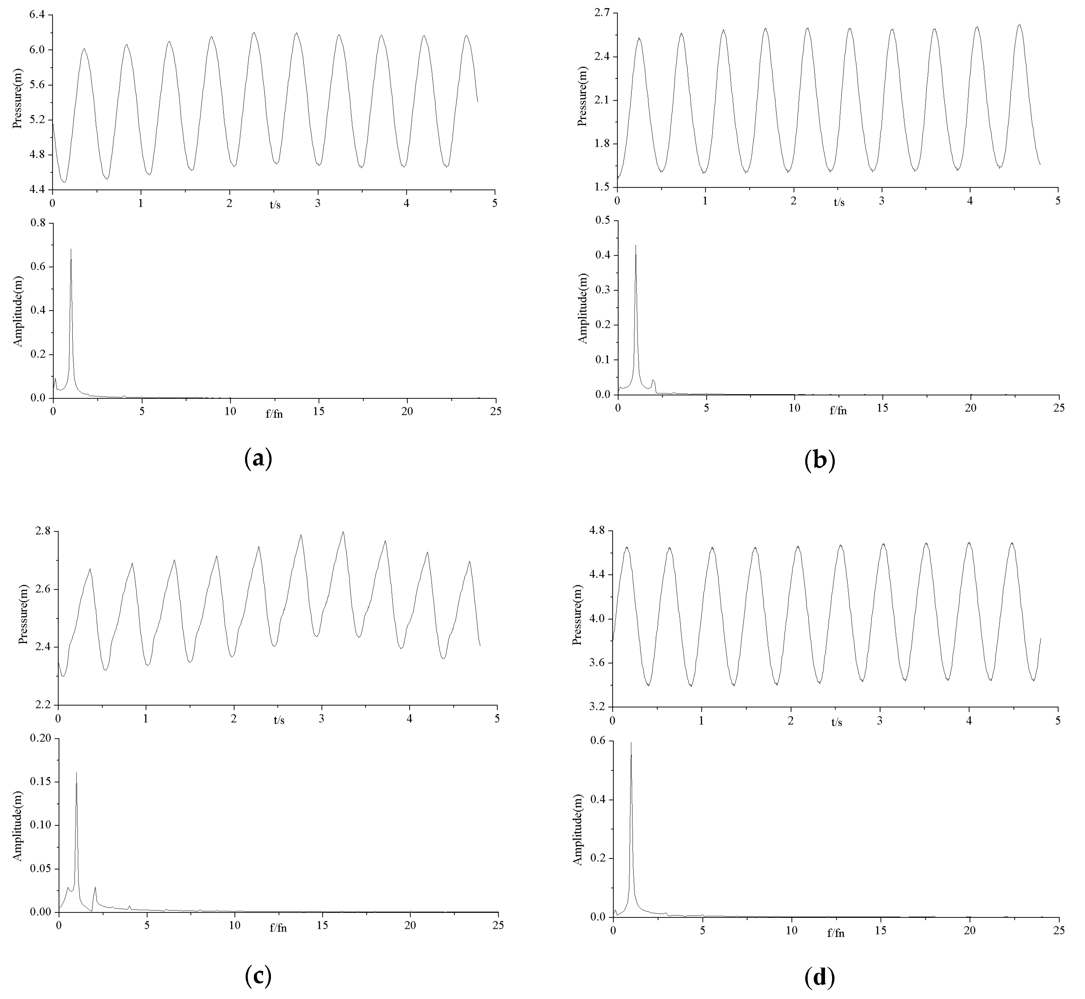
The time and frequency histories of the pressure pulsations at points RP and RS for the ebb and flood turbine modes for H = 3 m are shown in Figure 12 and Figure 13. The dominant frequencies of the pressure pulsations at the blade points are all 1fn due to their elevations periodically varying with the runner rotation. Frequencies that are multiples of fn are obvious in the pressure pulsations for point RS in the ebb turbine mode. Moreover, the frequency of 16fn, corresponding to 16 guide vanes (also known as rotor-stator interaction, RSI), commonly happens in a traditional turbine, and rarely has influence on this tidal turbine. This means the gravitational effect, rather than RSI, plays an important role in a low-head horizontal axial turbine.
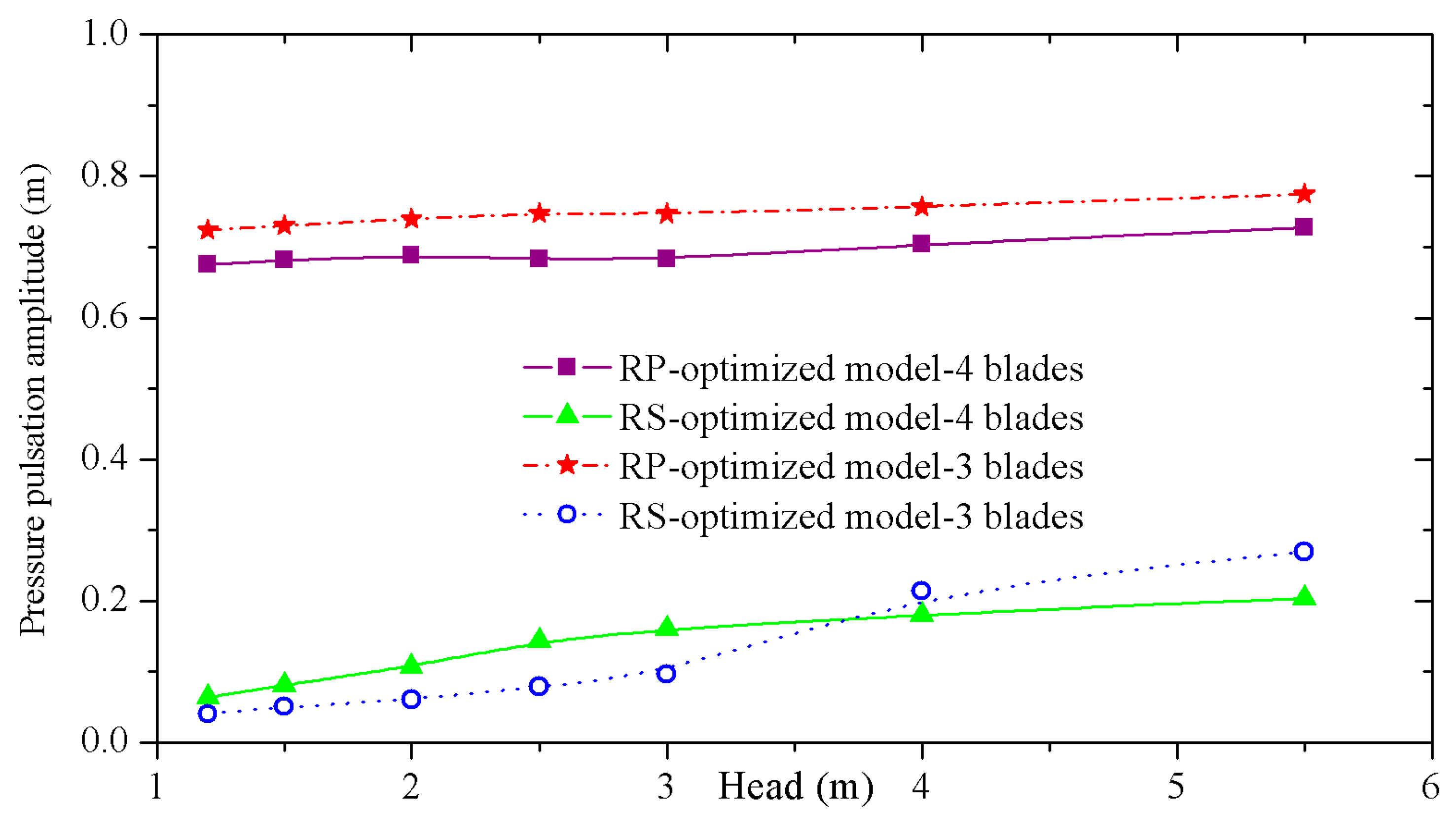
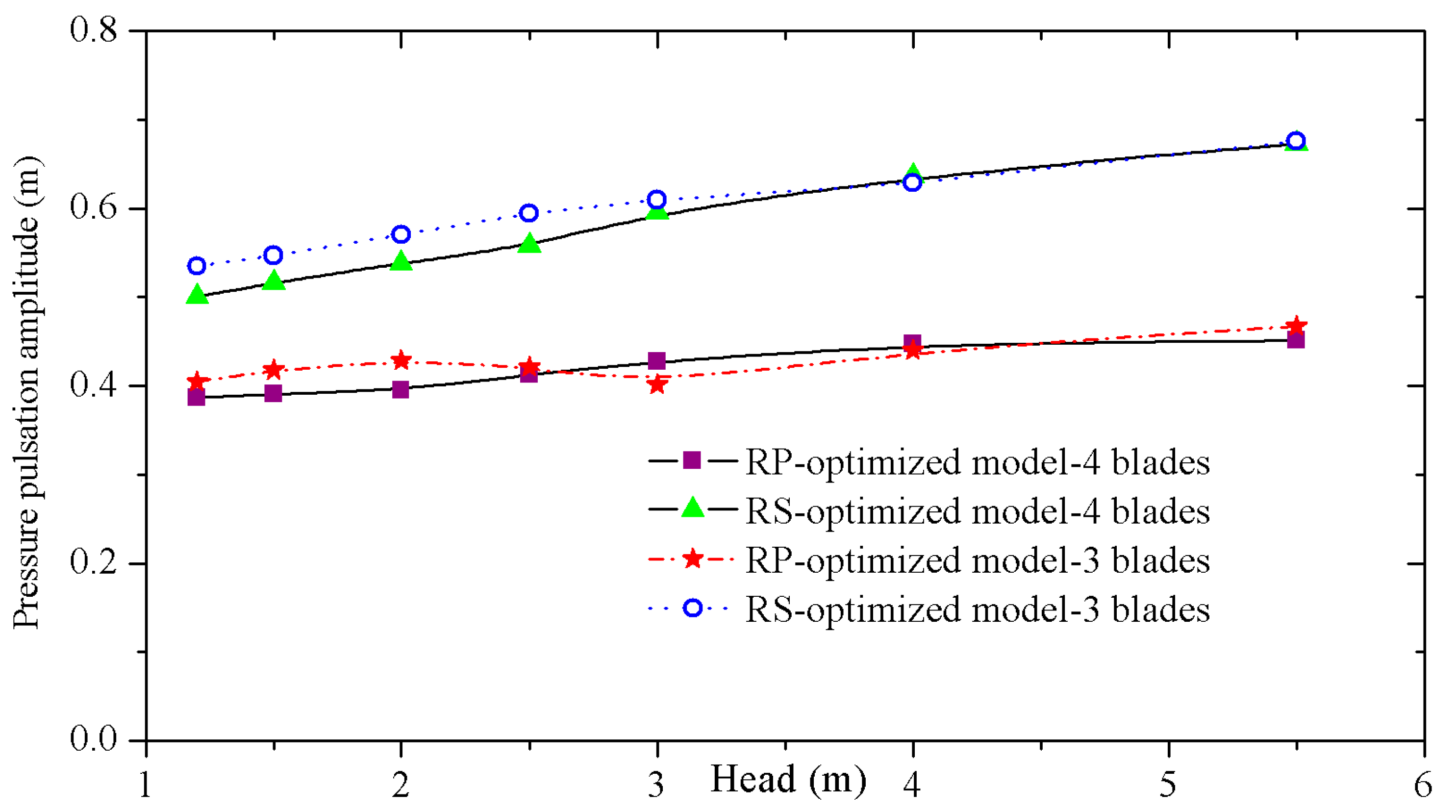
Figure 14 and Figure 15 show the amplitudes of the pressure pulsations with a dominant frequency of 1fn on blade points RP and RS for different heads.
Figure 14 shows that the amplitudes with dominant frequency of 1fn on blade points RP and RS tend to vary little for different heads, and the amplitudes on the suction side are much smaller than those on the pressure side. The amplitudes of the pressure pulsations on the pressure side are higher for the three-bladed runner than those for the four-bladed runner.
Figure 15 shows that the amplitudes with dominant frequency of 1fn on blade points RP and RS tend to linearly increase with the head for flood mode, while the amplitudes on the suction side (RP for flood mode) are smaller than those on the pressure side (RS for flood mode). The amplitudes of the pressure pulsations for the three-bladed runner are almost the same as those for the four-bladed runner.
5. Conclusions
This paper describes the complete optimization procedure for the design of a bidirectional tidal bulb turbine runner. The procedure consists of a design program, numerical flow analysis, and a multi-objective genetic algorithm which is completed in ANSYS Workbench automatically. The CFD results were used to generate RSM functions relating the design parameters and the objectives. The model tests were then conducted to validate the optimization results and confirm the final design. Using 3D numerical flow analysis in combination with the genetic algorithm is found to be an efficient approach for the design of the turbine runner, and it can reduce design time greatly. For the four-bladed turbine, the efficiency improvement is 5.5% in the ebb operation direction, and 2.9% in the flood operation direction; while for the three-bladed turbine, the efficiency improvement is 4.3% and 4.5%, respectively. The results of the pressure pulsations in the blade show that the gravitational effect, rather than RSI, plays an important role in a low-head horizontal axial turbine.
This research has accumulated experience for the design of larger tidal generation units in the future, which will precipitate utilization of tidal energy and be helpful for the improvement of the actuality of tidal energy utilization.
Acknowledgment
The authors thank Tsinghua University Initiative Scientific Research Program (No. 20151080459), National Natural Science Foundation of China (No. 51409148, no. 51439002), and the Jiangxia Tidal Test Power Station for supporting the present work.
Author Contributions
Zhengwei Wang conceived the study, Yongyao Luo and Xin Liu performed the numerical simulation, Yongyao Luo and Yexiang Xiao conceived and designed the model units. Chenglian He and Yiyang Zhang performed the model tests; Xin Liu analyzed the data; Yongyao Luo and Xin Liu wrote the paper.
Conflicts of Interest
The authors declare no conflict of interest.
References
- Rourke, F.O.; Boyle, F.; Reynolds, A. Tidal energy update 2009. Appl. Energy 2010, 87, 398–409. [Google Scholar] [CrossRef]
- Charlier, R.H. Forty candles for the Rance River TPP tides provide renewable and sustainable power generation. Renew. Sustain. Energy Rev. 2007, 11, 2032–2057. [Google Scholar] [CrossRef]
- Bernshtein, L.B. Tidal power plants in Russia. IEEE Power Eng. Rev. 1994, 14, 18–19. [Google Scholar] [CrossRef]
- Delory, R.P. The Annapolis tidal generating station. In Proceedings of the 3rd International Symposium on Wave, Tidal, OTEC and Small Scale Hydro Energy, BHRA, Brighton, UK, 14–16 May 1986. [Google Scholar]
- Wang, S.J.; Yuan, P.; Li, D.; Jiao, Y.H. An overview of ocean renewable energy in China. Renew. Sustain. Energy Rev. 2011, 15, 91–111. [Google Scholar] [CrossRef]
- Cho, Y.S.; Lee, J.W.; Jeong, W. The construction of a tidal power plant at Sihwa Lake, Korea. Energy Sources A Recovery Util. Environ. Eff. 2012, 34, 1280–1287. [Google Scholar] [CrossRef]
- Aggidis, G.A.; Feather, O. Tidal range turbines and generation on the Solway Firth. Renew. Energy 2012, 43, 9–17. [Google Scholar] [CrossRef]
- Lipej, A. Optimization method for the design of axial hydraulic turbines. Pro. Inst. Mech. Eng. A J. Power Energy 2004, 218, 43–50. [Google Scholar] [CrossRef]
- Yang, W.; Xiao, R.F. Multiobjective optimization design of a pump-turbine impeller based on an inverse design using a combination optimization strategy. J. Fluids Eng. 2014, 136, 014501. [Google Scholar] [CrossRef]
- Balint, D.; Câmpian, V.; Nedelcu, D.; Megheleş, O. Hydrodynamics automatic optimization of runner blades for reaction hydraulic turbines. In Proceedings of the 27th IAHR Symposium on Hydraulic Machinery and Systems, Montreal, QC, Canada, 22–26 September 2014. [Google Scholar]
- Loiseau, F.; Desrats, C.; Petit, P.; Liu, J. Bulb turbine operating at medium head: XIA JIANG case study. In Proceedings of the 27th IAHR Symposium on Hydraulic Machinery and Systems, Montreal, QC, Canada, 22–26 September 2014. [Google Scholar]
- Park, S.H. Modern Design of Experiments; Minyongsa: Seoul, Korea, 2001; pp. 121–140. [Google Scholar]
- Menter, F.R.; Rumsey, C.L. Assessment of two-equation models for transonic flows. Proccedings of the Fluid Dynamics Conference, Colorado Springs, CO, USA, 20–23 June 1994; pp. 1994–2343. [Google Scholar]
Figure 1.
The operating principal of the bidirectional tidal turbine.

Figure 2.
Four quadrant sketch of tidal unit operating condition transitions.

Figure 3.
Parametric representation of the blade. (a) 3D blade; (b) θ and β values in each section; (c) Definition of θ; (d) Definition of β.
Figure 3.
Parametric representation of the blade. (a) 3D blade; (b) θ and β values in each section; (c) Definition of θ; (d) Definition of β.

Figure 4.
Mesh of the flow path.

Figure 5.
Streamlines on the suction side of the blades at the optimum point.

Figure 6.
The standard test rig.

Figure 7.
Model units.

Figure 8.
The experimental torque acting on the runner versus discharge Q for the optimal three-bladed runner.
Figure 8.
The experimental torque acting on the runner versus discharge Q for the optimal three-bladed runner.

Figure 9.
Normalized efficiency vs. normalized Q11 for the ebb turbine mode.

Figure 10.
Normalized efficiency vs. normalized Q11 for the flood turbine mode.

Figure 11.
Locations of the recording points.

Figure 12.
Time and frequency histories of pressure pulsations on the blade points for an optimal four-bladed runner: H = 3 m. (a) RP-ebb mode; (b) RP-flood mode; (c) RS-ebb mode; (d) RS-flood mode.
Figure 12.
Time and frequency histories of pressure pulsations on the blade points for an optimal four-bladed runner: H = 3 m. (a) RP-ebb mode; (b) RP-flood mode; (c) RS-ebb mode; (d) RS-flood mode.

Figure 13.
Time and frequency histories of pressure pulsations on the blade points for an optimal three-bladed runner: H = 3 m. (a) RP-ebb mode; (b) RP-flood mode; (c) RS-ebb mode; (d) RS-flood mode.
Figure 13.
Time and frequency histories of pressure pulsations on the blade points for an optimal three-bladed runner: H = 3 m. (a) RP-ebb mode; (b) RP-flood mode; (c) RS-ebb mode; (d) RS-flood mode.

Figure 14.
Pressure pulsation amplitudes with dominant frequency of 1fn on blade points RP and RS for the ebb turbine mode.
Figure 14.
Pressure pulsation amplitudes with dominant frequency of 1fn on blade points RP and RS for the ebb turbine mode.

Figure 15.
Pressure pulsation amplitudes with dominant frequency of 1fn on blade points RP and RS for the flood turbine mode.
Figure 15.
Pressure pulsation amplitudes with dominant frequency of 1fn on blade points RP and RS for the flood turbine mode.


Table 1.
Main parameters of the prototype unit.
| Design Parameters | Value | Geometric Parameters | Value |
|---|---|---|---|
| Design head (H) | 2.5 m | Runner diameter (D) | 2.5 m |
| Design discharge (Ebb turbine) | 34 m3/s | Hub ratio | 0.9 |
| Design discharge (Flood turbine) | 27 m3/s | Blade number | 3 or 4 |
| Rotational speed (n) | 125 r/min | Guide vane number | 16 |
Table 2.
Angles in initial and optimal conditions.
| Model | Angle Value (°) | |||||||||
|---|---|---|---|---|---|---|---|---|---|---|
| β11 | β12 | β21 | β22 | β31 | β32 | β41 | β42 | β51 | β52 | |
| Initial model: four-bladed | 66.6 | 66.8 | 62.5 | 61.2 | 52.7 | 50.7 | 50.3 | 44.2 | 34.5 | 39.3 |
| Optimal model: four-bladed | 56.2 | 60.1 | 50.5 | 54.5 | 44.3 | 48.1 | 40.2 | 42.4 | 36.5 | 44.5 |
| Optimal model: three-bladed | 61.3 | 60.8 | 61.1 | 60.1 | 58.8 | 58.8 | 51.8 | 53.3 | 36.1 | 45.3 |
| θ11 | θ12 | θ21 | θ22 | θ31 | θ32 | θ41 | θ42 | θ51 | θ52 | |
| Initial model: four-bladed | 53.1 | 120.7 | 53.0 | 123.1 | 52.6 | 123.7 | 52.1 | 124.3 | 51.2 | 121.4 |
| Optimal model: four-bladed | 62.5 | 117.5 | 55.6 | 125.8 | 52.1 | 130.5 | 50.5 | 131.2 | 55.3 | 125.1 |
| Optimal model: three-bladed | 61.2 | 116.0 | 53.1 | 122.2 | 48.9 | 126.1 | 46.2 | 128.7 | 41.3 | 131.4 |
© 2017 by the authors. Licensee MDPI, Basel, Switzerland. This article is an open access article distributed under the terms and conditions of the Creative Commons Attribution (CC BY) license (http://creativecommons.org/licenses/by/4.0/).
Share and Cite
MDPI and ACS Style
Luo, Y.; Liu, X.; Wang, Z.; Xiao, Y.; He, C.; Zhang, Y. Optimization of the Runner for Extremely Low Head Bidirectional Tidal Bulb Turbine. Energies 2017, 10, 787. https://0-doi-org.brum.beds.ac.uk/10.3390/en10060787
AMA Style
Luo Y, Liu X, Wang Z, Xiao Y, He C, Zhang Y. Optimization of the Runner for Extremely Low Head Bidirectional Tidal Bulb Turbine. Energies. 2017; 10(6):787. https://0-doi-org.brum.beds.ac.uk/10.3390/en10060787
Chicago/Turabian StyleLuo, Yongyao, Xin Liu, Zhengwei Wang, Yexiang Xiao, Chenglian He, and Yiyang Zhang. 2017. "Optimization of the Runner for Extremely Low Head Bidirectional Tidal Bulb Turbine" Energies 10, no. 6: 787. https://0-doi-org.brum.beds.ac.uk/10.3390/en10060787
Note that from the first issue of 2016, this journal uses article numbers instead of page numbers. See further details here.