On the Mathematical Modeling of Line-Start Permanent Magnet Synchronous Motors under Static Eccentricity


Electrical Engineering Department, King Fahd University of Petroleum and Minerals, Dhahran 34464, Saudi Arabia
*
Author to whom correspondence should be addressed.
Energies 2018, 11(1), 197; https://0-doi-org.brum.beds.ac.uk/10.3390/en11010197
Submission received: 15 November 2017
/
Revised: 27 December 2017
/
Accepted: 28 December 2017
/
Published: 16 January 2018
(This article belongs to the Section F: Electrical Engineering)
Abstract
:Line start permanent magnet synchronous motors experience different types of failures, including static eccentricity. The first step in detecting such failures is the mathematical modeling of the motor under healthy and failed conditions. In this paper, an attempt to develop an accurate mathematical model for this motor under static eccentricity is presented. The model is based on the modified winding function method and coupled magnetic circuits approach. The model parameters are calculated directly from the motor winding layout and its geometry. Static eccentricity effects are considered in the motor inductances calculation. The performance of the line start permanent magnet synchronous motor using the developed mathematical model is investigated using MATLAB/SIMULINK® software (2013b, MathWorks, Natick, MA, USA) under healthy and static eccentricity condition for different loading values. A finite element method analysis is conducted to verify the mathematical model results, using the commercial JMAG® software (16.0.02n, JSOL Corporation, Tokyo, Japan). The results show a fine agreement between JMAG® and the developed mathematical model simulation results.
1. Introduction
Electrical motors play a major role in industrial sectors around the world. They are the backbone of industry and manufacturing. Statistics show that electrical motors consume about two-thirds of the total industrial power consumption in each society [1]. Induction motors constitute by far the largest portion of electrical motors in the market. However, more efficient motors are beginning to appear as other alternatives. A recently manufactured motor, which is used in industrial practices, is the Line-Start Permanent Magnet Synchronous (LSPMS) motor. This motor has a self-starting capability as induction motors due to rotor cage and attains the synchronous speed due to rotor magnets. Under normal operating conditions, a great deal of research work has investigated the LSPMS motor in terms of modeling, efficiency, and energy consumption [2]. The researcher also presents the challenges that are faced by this motor, such as the breaking torque and construction cost [3]. It was shown that this motor enjoys a higher efficiency than induction motors, which in turn, reflected on the energy and money saving benefits [4,5]. As a result, this will open the door for greater penetration in the market. H. Behbahanifard et al. [6] introduced a comprehensive survey of the work done on the modeling trends of healthy LSPMS motor, which includes the initial start and synchronization process, cogging torque, and the armature reaction during the starting process, which results in permanent magnet demagnetization. Kahourzade et al. [7] focused on modeling with more emphasis on the dynamic and steady state behavior of the motor where the LSPMS motor (3-phase, 4-pole, 2 kW) was compared with a similar rating induction motor. It was found that the LSPMS motor had higher efficiency and can withstand overload conditions more than the induction motors. Besides, the starting current for the LSPMS motor is lower than the induction motor at the same load condition. On the same manner, a high performance LSPMS motor model was developed from an existing induction motor model in [5]. Dan Stoia et al. [8] proposed an analytical method to analyze a LSPMS motor based on a magnetic equivalent circuit and a dynamical qd0 reference frame model. The needed equations for the proper design of the LSPMS motors were presented. The operating point of the permanent magnet was determined analytically, considering the armature reaction effect.
Electrical motors consist of many parts, which are mainly electrical and mechanical, such as stator and rotor winding, rotor bars or damper windings, bearings, and rotor magnets in the Permanent Magnet Synchronous Motor (PMSM) and LSPMS motors. Those parts are exposed to failure due to many reasons, such as mistakes during repair and non-ideal operational environment, such as dust, vibrations, high temperature, etc. [9,10]. The electrical faults include windings short-circuit or inter-turn faults, and rotor permanent magnets demagnetization due to armature reaction effect. Mechanical faults consist of airgap eccentricity, broken rotor bars, and bearing damage. Among those faults, 40% of faults are related to bearing damage, 38% are stator related faults, 10% are rotor related faults, and 12% are external and other faults [11]. As any other motor, LSPMS motors may experience different kinds of faults. Airgap Eccentricity related faults are responsible for about 5 to 15 % of the total faults. It happens when there is a non-uniform distance between stator inner race and rotor outer race, which in turn, will result in an unbalance magnetic field in the airgap. The unbalanced magnetic flux will lead to having a non-uniform flux linking both the stator and rotor circuits. This will affect mainly the motor inductances due to the non-uniform air gap distance. Moreover, the synchronization process and time variation of the stator current will be affected. There will be an injection of harmonics in the stator line current [12]. Eccentricity faults are attributed to many reasons, such as overloading, overstress in thermal and pressure circumstances, rotor misalignments, and bearing faults, which will result in motor shaft vibration and acoustic noise, which could completely damage the motor [13]. Three types of eccentricity can occur in electrical motors: static, dynamic, and mixed eccentricity [9]. The static eccentricity fault condition occurs when the rotor is at a constant offset from the stator symmetry axis and rotates with the new center of rotation, which has a specific offset from stator center. Thus, the minimum air gap distance is constant. However, the motor rotor is rotating at another center, rather than the symmetry center [14].
Various methods were presented in the literature for modeling and simulating eccentricity faults, the majority are based on the finite element analysis method or coupled magnetic circuit approach and the modified winding function method (MWFM). The finite element method (FEM) is considered as one of the most accurate methods to simulate the motor behavior [15,16,17,18]. However, it requires a knowledge of detailed motor parameters in addition to the internal construction of the motor to represent the geometry model. This method is a time-consuming process, even for a powerful computer, and will not provide as simple analytical modeling expressions as the MWFM method [19]. On the other hand, the MWFM can be used to calculate the motor inductances under the static eccentricity fault to represent the non-uniform airgap [20]. Moreover, the results obtained from the MWFM are verified using the finite element method for validation purposes.
The MWFM depends on the winding configuration and the positional relationship of the stator and rotor coils along with the physical motor dimensions. It is based on the Ampere and Gauss laws that drive the various motor inductances, which include the effect of space harmonics [21]. The MWFM is widely introduced to simulate and model electrical motors both in healthy and under internal motor fault conditions in both synchronous and induction machines. It is utilized for the first time in [22] for internal winding fault analysis, and consequently in [23,24], for rotor faults. LSPMS motors behave like induction motors in the starting process and operate in a steady state as the synchronous motors. Therefore, it is important to review the methods of eccentricity modeling, both in induction and synchronous motors. Nandi et al. [25] modeled the mixed eccentricity in three phase induction motors based on the MWFM along with the finite element analysis to compute the motor inductances. Frequency analysis of stator current is utilized as a detection scheme. The same methodology was followed in [26] by performing a dynamical simulation to the induction motor under the mixed eccentricity fault. In [13], the authors present a closed form expression for calculating the inductance matrices in induction motors under eccentricity conditions where a new technique based on the winding function method is proposed to model the eccentricity. Toliyat et al. [12] introduced the MWFM to present a new model of the induction motor under airgap eccentricity. The authors developed the mathematical model based on the magnetically coupled circuit approach, and represent the eccentricity by modifying the inductance matrices of the motor. Wu et al. [27] used the same principle in separating the load oscillation and rotor fault effects in the stator current based on MWFM.
Eccentricity analysis in synchronous motors is similar to the induction motors. The authors in [28] present a new index for detecting the dynamic eccentricity, which is based on the modified winding function method in the round rotor synchronous motors. This index is based on processing the developed torque using the time series data mining (TSDM) method. The authors also investigated the load variation in [29] under eccentricity conditions. The authors showed that the load variation has no impact on the amplitude of stator current harmonics since the motor is running at a constant speed. The same approach was used in [30] to present a novel method for modeling dynamic eccentricity in salient-pole synchronous motors. The coupled magnetic circuit approach has been used for simulating this fault. The main key for this simulation is to determine the machine inductances under healthy and faulty cases. Besides, the winding function method was used in [31] for calculating the mutual inductance between the stator and rotor in the LSPMS motor. The authors presented the rotor as portions; each part has a high permeability and is separated by one layer of low permeable material. The finite element method is used to confirm the simulation results.
In regards to the analysis of LSPMS motors under static eccentricity fault condition, few attempts were recently published [14,32,33]. They all simulate the motor using the FEM. Therefore, this paper is devoted for the development of a mathematical model and analyzing the performance of LSPMS motor under static eccentricity fault condition. The developed model will be used to simulate the motor transient and steady state performance using MATLAB® software in qd0 synchronously reference frame. Results will be compared to FEM analysis using JMAG® to judge the model accuracy. The effect of static eccentricity on the motor’s line current, speed, and torque characteristics will be investigated. The paper is organized as follows. The next section present the development of mathematical models for the LSPMS motor under healthy and static eccentricity conditions. Section 2 will also include the developed JMAG FEM model. Section 3 presents detailed simulation results and analysis for both the developed mathematical model and JMAG FEM simulation. Finally, some conclusions and possible future work is presented in Section 4.
2. Mathematical and FEM Modeling of LSPMS Motors
This section presents the dynamical and FEM modeling of LSPMS motor under healthy and static eccentricity condition.
2.1. Dynamical Model of LSPMS Motor under Healthy Conditions
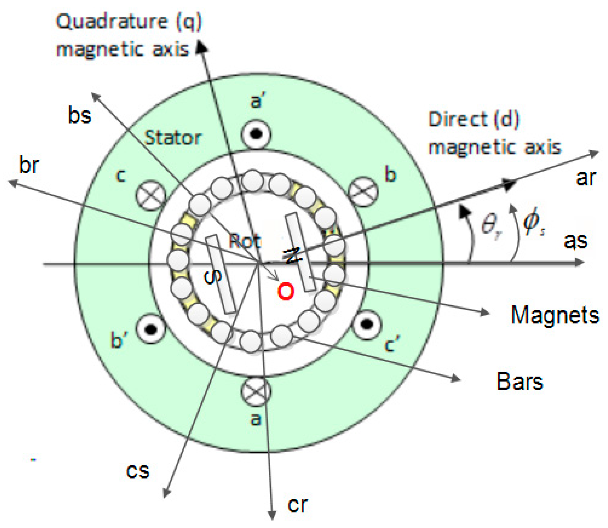
The healthy abc-LSPMS motor model is well known [2,34]. To drive this model, some assumptions should be made, which are: the stator winding distribution is sinusoidal, the iron magnetic permeability is infinite, and the magnetic operating point is assumed to have a fixed value and located in the linear region. Figure 1 shows the motor stator and rotor circuits assuming two pole motor. The origin of coordinate , and the winding axis of stator and rotor, as well as the quadrature and direct axis of magnet are also shown on the same figure.
By using the coupled magnetic circuit approach and Kirchhoff’s law, the stator and rotor voltage equations can be written as:
where and are the stator and rotor terminal voltages. and are the stator and rotor phase resistances. and are stator and rotor phase currents. and are the stator and rotor flux linkages. For conciseness, matrix expressions are used to donate three phase variables, as follows.
The stator magnetic fluxes are generated by three different sources, which are: the flux created by self-inductances , the second is formed by the mutual inductance between stator and rotor , and finally, the permanent magnet flux . The same analogy is applied for the rotor magnetic flux . The total flux linkage equations can be written in matrix format as:
where are the stator self-inductance, stator to rotor mutual inductance, rotor to stator mutual inductance, and rotor self-inductance matrices, respectively. and are the permanent magnet flux component for stator and rotor, respectively. is the peak value of the PM flux. is the reference angle of the PM flux vector. The diagonal elements of and are the self-inductances of stator and rotor windings, while the off-diagonal elements are the mutual inductances. They can be calculated under healthy condition using the winding function method approach [28]. Park transformation [35] in the rotor reference frame is used to transform the abc-LSPMS motor model into qd0-model. This yields (6)–(10), which complete the model for the healthy LSPMS motor.
where is the electrical angular speed. and are the qd0 magnetizing inductances, respectively. are the leakage inductances of stator and rotor windings, respectively. and is the equivalent magnetization current referred to stator side. The prime notations in the last equations indicates a variable being referred to stator side. It should be noticed that the rotating reference frame is assumed to be on the rotor side. Therefore, the permanent magnet flux component, at the stator side, is changed as a sinusoidal wave form. In qd0 reference frame, this component is available along the d-axis only for the stator and rotor.
The mechanical speed is expressed in (9) as:
where is the number of poles, is the motor inerita, is the input mechanical load, is the damping torque, and is the rotor angular velocity. Finally, the electromechanically torque that is developed by the motor can be obtained from the input power being transferred into the airgap [34], which is given by:
2.2. Dynamical Model of LSPMS Motor under Static Eccentricity Condition
Eccentricity, in general, will affect the motor inductances. Thus, the previously presented inductance matrices in a healthy condition, as shown in (4), are not valid for the model under the static eccentricity fault condition [36]. In this paper, coupled magnetic circuit approach is used to represent the abc-LSPMS motor model under static eccentricity fault condition, while the MWFM is used for estimating the motor inductances. This section will include the modeling of the airgap function and inductance calculation under this fault.
2.2.1. Modeling of Static Eccentricity
Eccentricity is a mechanical related fault; the occurrence of static eccentricity will change the motor rotational axis symmetry. Therefore, considering the non-uniform airgap distribution is necessary. According to [36], the airgap permeance is inversely proportional to the airgap length, as shown in (11). Thus, the airgap permeance can be neglected for points far from the rotor poles.
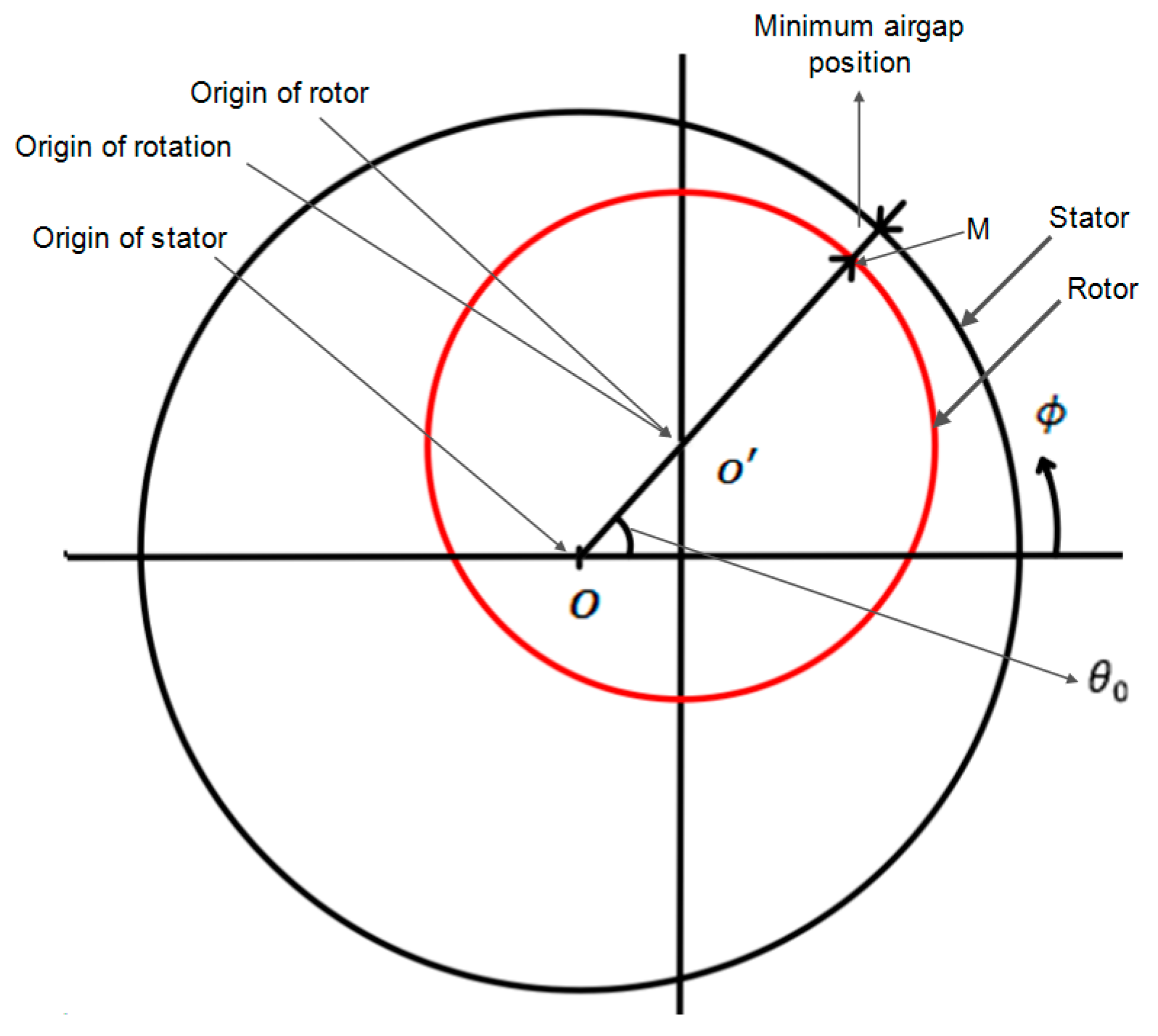
where , and are the permeability in space, the average radius of airgap, the airgap function, and the base angle for measurement, respectively. Figure 2 presents the motor geometry with static eccentricity. The rotor center of rotation is offset from the center of stator to represent an eccentric rotor. Vector is called the static eccentricity vector. The degree of static eccentricity is defined as the ratio between the magnitude of static eccentricity vector to the symmetrical airgap length [14], yields:
This vector is fixed in space under static eccentricity and its position is characterized by angle . This angle describes the stationary position of the minimum airgap along the inner stator surface. For an arbitrary point M located on the rotor outer race, the distance between this point and the rotor center is equal to rotor radius [37], or:
where is the rotor outer radius. For stator inner radius of , the airgap function can be obtained as:
Hence, the rotor radius is much larger than the airgap length, the second term in (13) can be represented by . Therefore, (14) can be written as:
For the calculation of the inductances in the MWFM, the inverse of the airgap function is needed. It is represented in (16) as [37]:
The above equation can be expressed in Fourier series form as:
The series coefficients and can be obtained as:
The inverse function for the first term can be written as:
2.2.2. Inductance Calculations under Static Eccentricity
The MWFM will be used to derive the motor inductances under static eccentricity fault. A detailed discussion about this method is reported in [20]. This method assumes two set of arbitrary winding A and B. The self and mutual inductance between these two winding can be written as:
where is the self-inductance of winding a, is the mutual inductance linking winding b due to current flow in winding a. is a reference angle along the stator inner surface. The terms , , and are the modified winding function of winding a, and the turn functions for winding a and b, respectively. The modified winding function for arbitrary winding a is defined as:
where is the average value of (19) and equal to:
The inductance matrices as presented in (4), for the healthy condition, should be recalculated under static eccentricity fault condition. For this purpose, MATLAB® symbolic integration method is used to calculate the total 27 inductance elements in the matrices based on (20) and (21). The flux linkage equations under static eccentricity fault condition can be written as:
where , , , are the inductance matrices under the static eccentricity fault condition. The diagonal elements of and in (25) are the self-inductances of stator and rotor windings, and they are calculated using (20), while the off-diagonal elements are the mutual inductances and they are calculated using (21). Park transformation [35] in the rotor reference frame is used to transform the abc-LSPMS motor flux linkage equations in (24) into qd0-reference frame. This yield Equations (26)–(30), which complete the model for the faulty LSPMS motor under static eccentricity.
where , , , and are the transformed stator self-inductance, stator to rotor mutual inductance, rotor to stator mutual inductance, rotor self-inductance matrices under the faulty condition, respectively. is an inductance component due to static eccentricity. is the average radius of the airgap. is the average length of the motor stack. is the number of pole pairs. is the saliency ratio. is the equivalent number of winding turns.
In conclusion, it should be noticed that static eccentricity have no effects on the form of the voltage equations obtained in (7) and (8). Therefore, the LSPMS motor mathematical model under eccentricity condition is represented by (7)–(9) and (26)–(32).
2.3. Modeling of LSPMS Motor Using FEM
The finite element method is a numerically based approach used for computing the motor performance characteristics and parameters, such as current, torque, speed, flux density, and inductances. This method will handle the complex motor geometry, consider the mixed set of materials that are involved in the motor parts, and, in addition, monitor the non-linear behavior of these materials such as permanent magnets. In this method, the motor geometry will be divided into an enormous number of elements joined with nodes by using a proper discretization and mesh generation algorithms. A set of equations represents each element, and the entire set of equations and their solutions will implement the motor model.
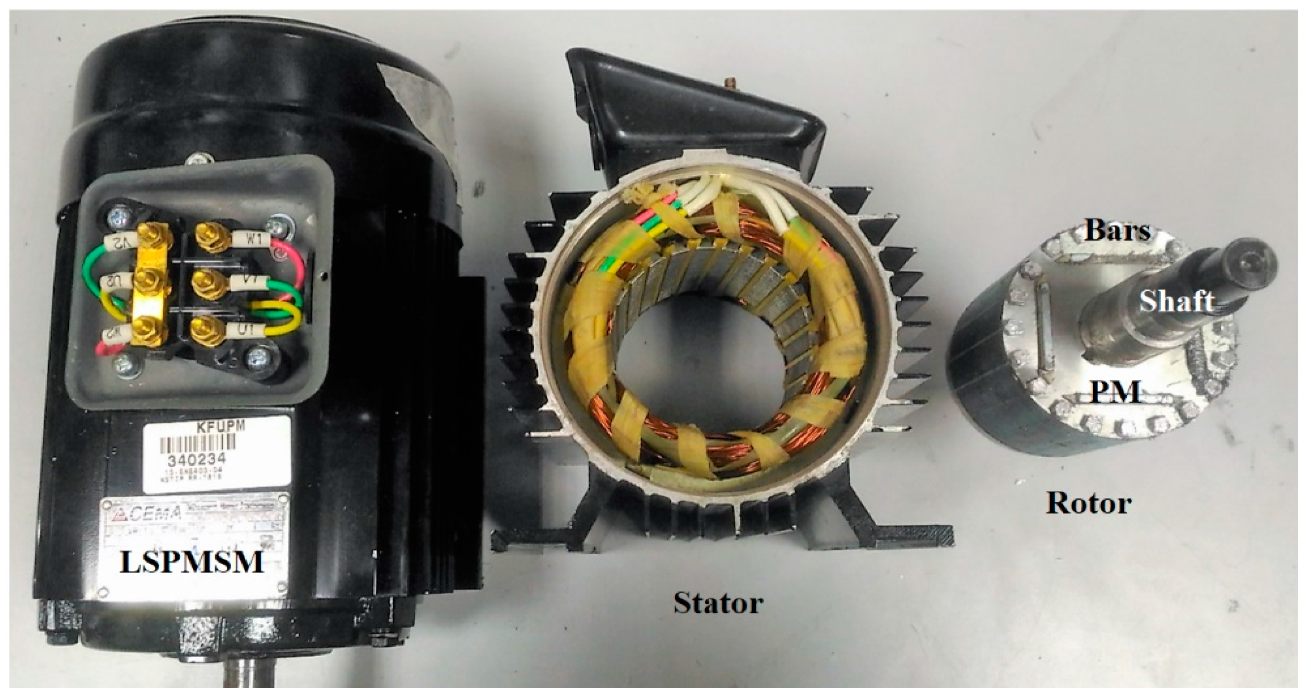
To ensure the accuracy of developed mathematical model, FEM based analysis is performed for three phase LSPMS motor (1-hp, 415 V, Y-connected, four-pole) utilizing JMAG® designer software. JMAG is an electromagnetic simulation program that was developed by JSOL Corporation. JMAG provides a two-dimensional (2-D)/three-dimensional (3-D) platform to construct motor models. Material properties can be assigned to each part of the model. JMAG includes a material library based on commercial and industrial materials. The material properties and names are obtained from the manufacturer’s data sheets and brochures. Additional materials can be easily added, along with their complete mechanical, electrical and magnetic properties. Moreover, the available material can be customized based on the application. Figure 3 shows the motor that was used in the study. To create the finite element model, the motor geometry was drawn using Auto-CADTM and then imported into JMAGTM.
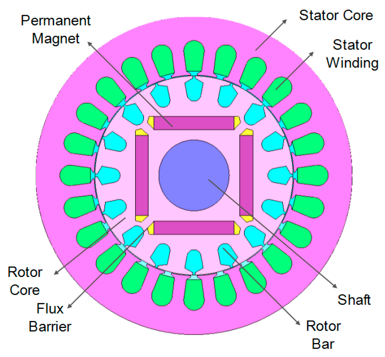
The motor geometry specifications and electrical parameters are shown in Table 1. Figure 4 presents the geometry model of the motor. The model consists of all the geometrical parts, which include the laminated silicon steel core of the stator and rotor, stator copper windings, shaft, rotor casts aluminum bars, and the permanent magnet of type 24HE. The monolayer topology is used for stator winding distribution, and this will reduce the total harmonics in the line voltage and current. The transient iterative solver of JMAG®, based on incomplete Cholesky conjugate gradient (ICCG) method, is used to solve for magnetic field distribution in the model, as well as the other motor performance characteristics, such as stator current, speed, and torque.
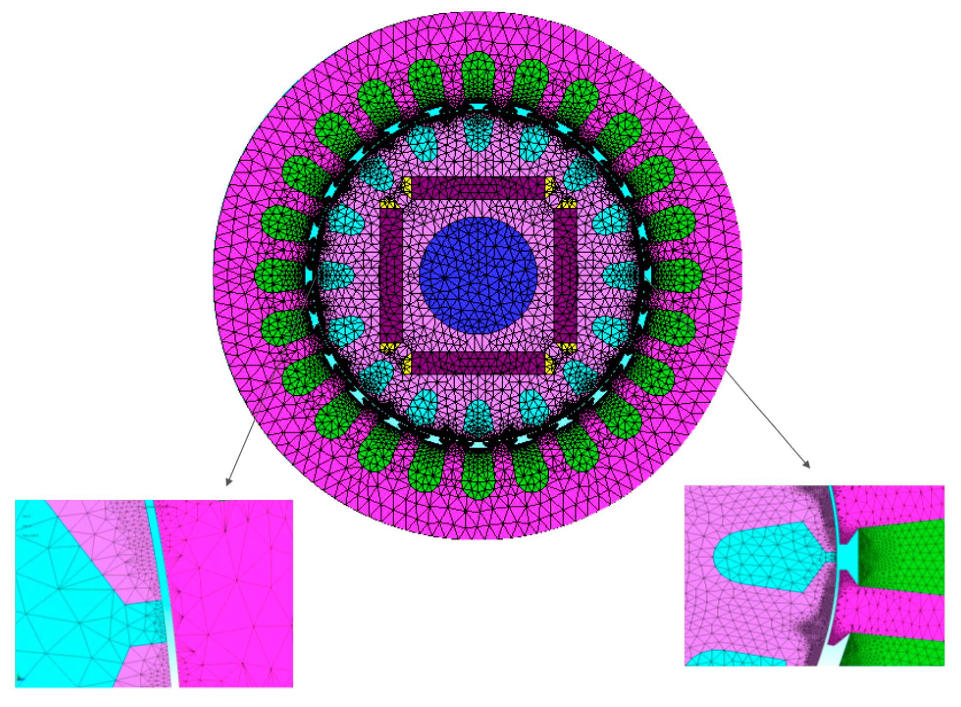
The 2-D mesh model of the motor is created with 70,729 nodes and 133,803 elements. Figure 5 shows the resulting mesh model of LSPMS motor.
3. Simulation Results
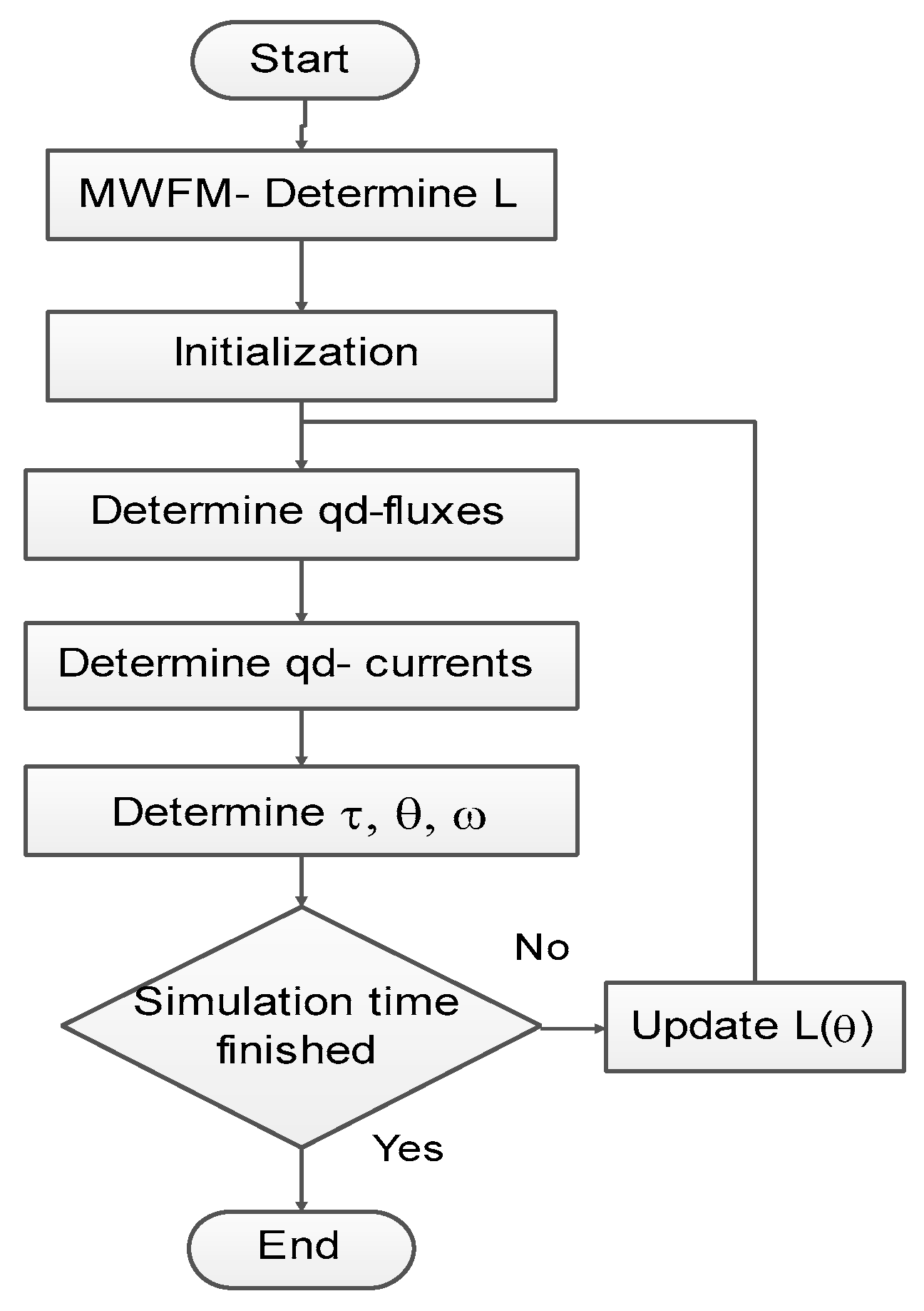
The simulation results are divided into two main parts. First, a comparison between the simulation results of the MATLAB® and JMAG® models is presented under healthy conditions. The second part will contain the simulation results under static eccentricity fault conditions. This section will include a simulation and comparison of 21 cases, using JMAG® and MATLAB®. They will cover a wide range of eccentricity degrees under different loading conditions. Also, the angle effect of the static eccentricity vector along the motor circumference has been studied. The simulation results will be compared in terms of stator current, speed, and torque characteristics. Figure 6 presents the flow chart of modeling and simulation using MATLAB®.
The simulation starts by determining the inductance matrices given in (26). Simulation is initialized for the 1-hp LSPMS motor with parameters given in Table 1. Three phase sinusoidal voltages are applied to the motor terminals. By rearranging (7) and (8), the quadrature and direct fluxes are calculated after performing the integration. The inductance matrices calculated in (26) will be used to determine the current in qd0 reference frame. From the fluxes and currents calculated, the electromagnetic torque, rotor angular position , and speed are determined using (9). The performance of the LSPMS motor will be investigated under the normal operating loads. The selected degrees of static eccentricity (SE) based on (12) will be in the range of 13 to 33%. Under 10% SE, a small variation is expected in the motor line current, speed, and torque characteristics. This is due to intrinsic SE in the normal operation of the motor, which was estimated to be around the 10% [32].
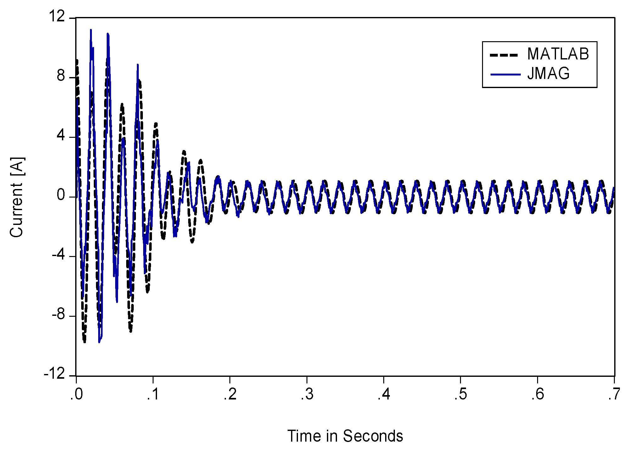
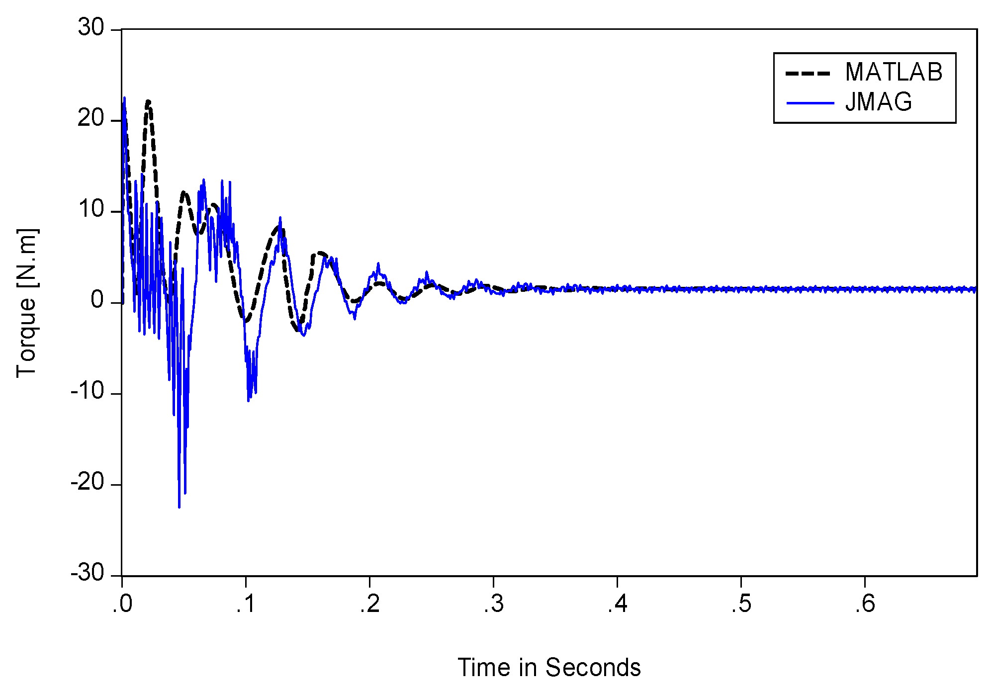
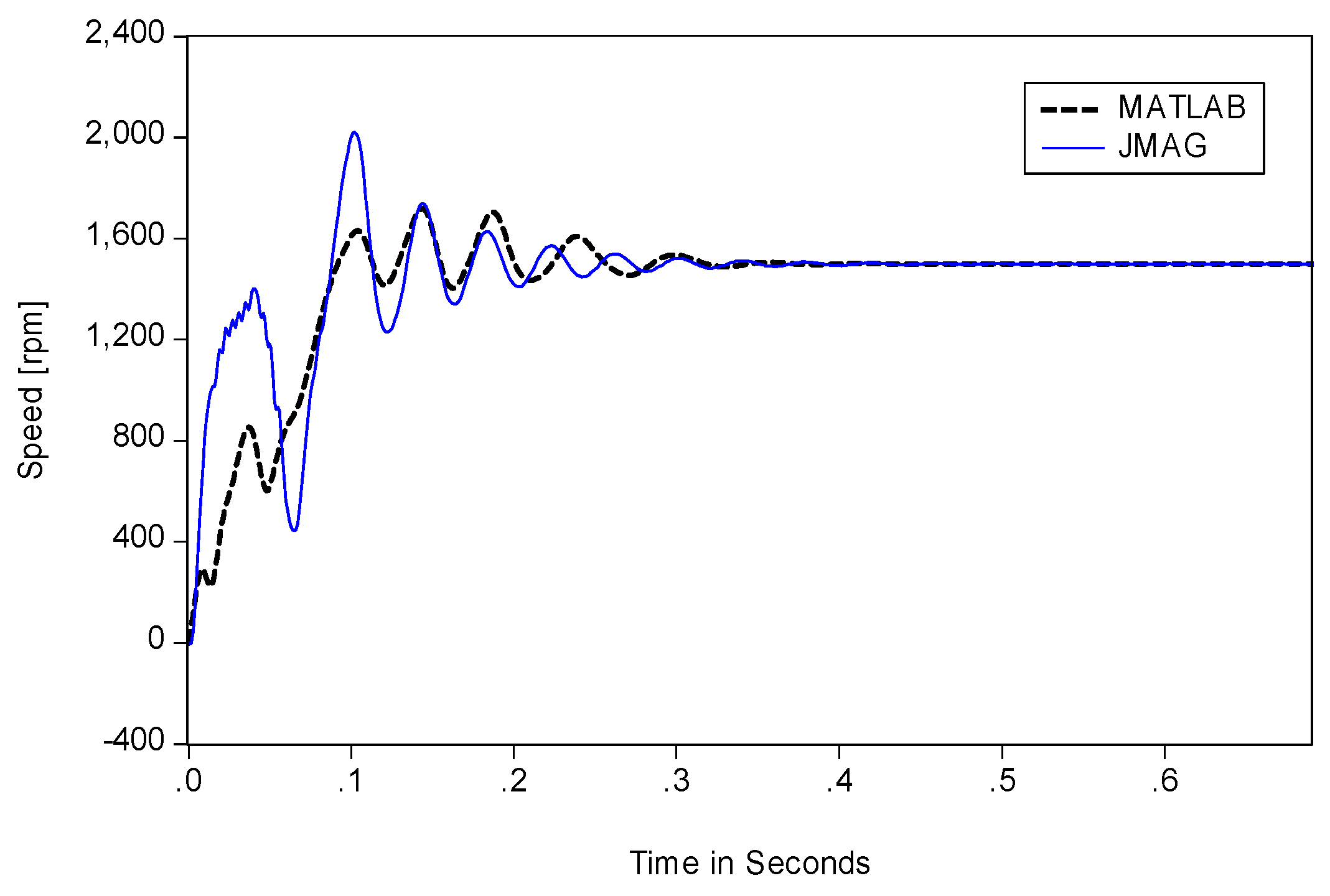
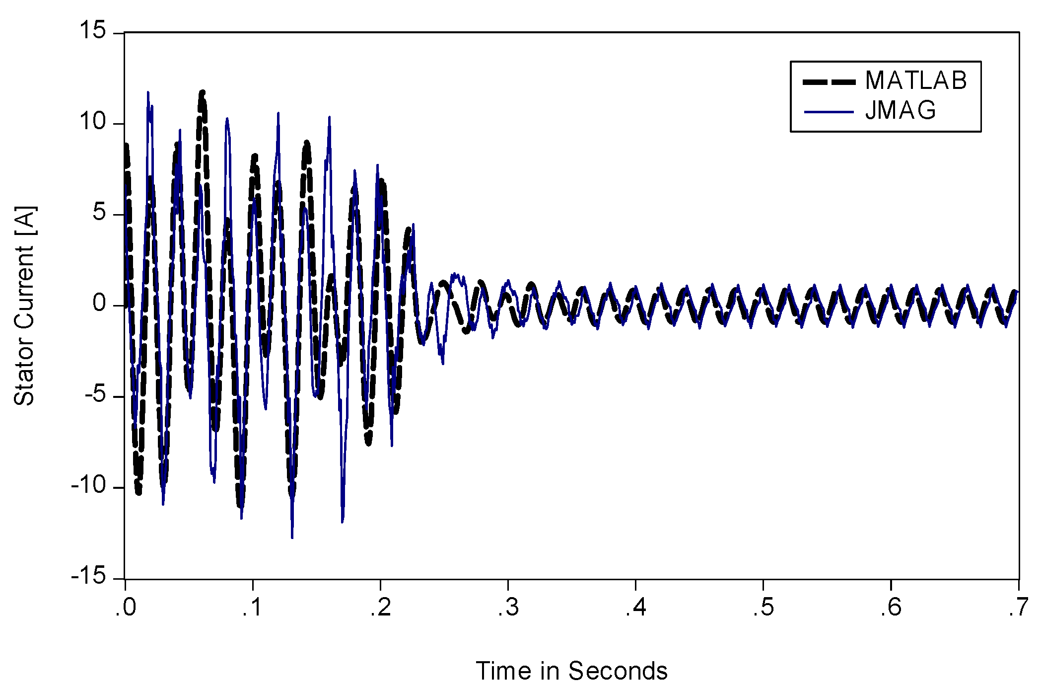
To verify the accuracy of the derived model under different loading and eccentricity conditions, the LSPMS motor is simulated using JMAG® and MATLAB®. Figure 7, Figure 8 and Figure 9 show the stator current, electromagnetic torque, and speed for a load of 1.5 N·m. Results show a good agreement between JMAG® and MATLAB® results from the developed model. The stator current shows very similar time variations in transient and steady state operation. Moreover, the torque and speed characteristics of the developed mathematical model follow the same behavior of the FEM simulation results. It should be noticed that the inductance matrix is calculated using the MWFM. The inductance matrix is not constant over the entire simulation time. In transient region, the inductance matrix is changing due to current as well as flux changes. The simulation is started by setting some initial values for the flux. Therefore, to find the corresponded current value due to that flux, the inductance matrix is derived as a function of the rotor angular position. Thus, the calculated inductance value will be a function of that current, torque, and angular position. In steady state, the current and torque quantities will reach a steady state value. Therefore, the inductance matrix elements will have a constant value. This applies for both the healthy and faulty conditions.
To demonstrate the accuracy of the developed model under eccentricity condition, Figure 10 depicts the stator current under 19% static eccentricity for 2.1 N·m load. The similarity of time variations between MATLAB® and FEM results are clear.
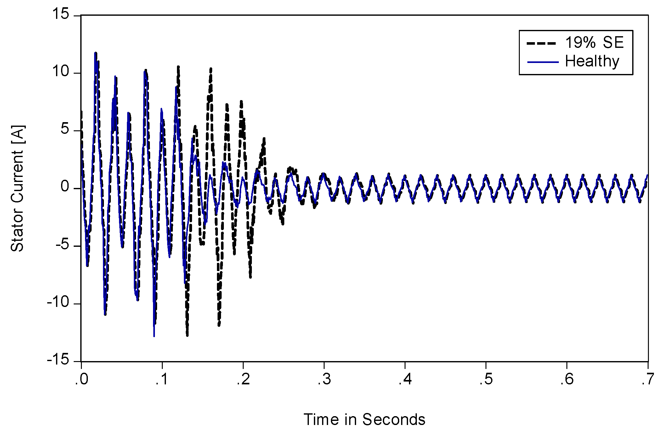
Figure 11 shows a comparison between the healthy and faulty stator currents under 19% SE and a load of 2.1 N·m. It is quite clear that under this degree of SE, it takes a longer time to attain a steady state value than a healthy condition Also, higher current peaks are presented in the transient region.
For further comparison between FEM and the developed mathematical model results, Table 2 presents the correlation and the normalized mean square error (NMSE) for 21 cases of different loading conditions and static eccentricity degrees. As reported in the literature, it is useful to pay more attention to the stator current as the fault diagnostic techniques, such as motor current signature analysis (MCSA), are based on the stator current waveform. The NMSE is defined as:
where and are the JMAG® and MATLAB® stator current time variation values divided by the maximum value of each time series, respectively. is the number of samples per each series.
The correlation coefficient is a statistical measure of dependence between two variables, and it is also an indicator of how two variables fluctuate together.
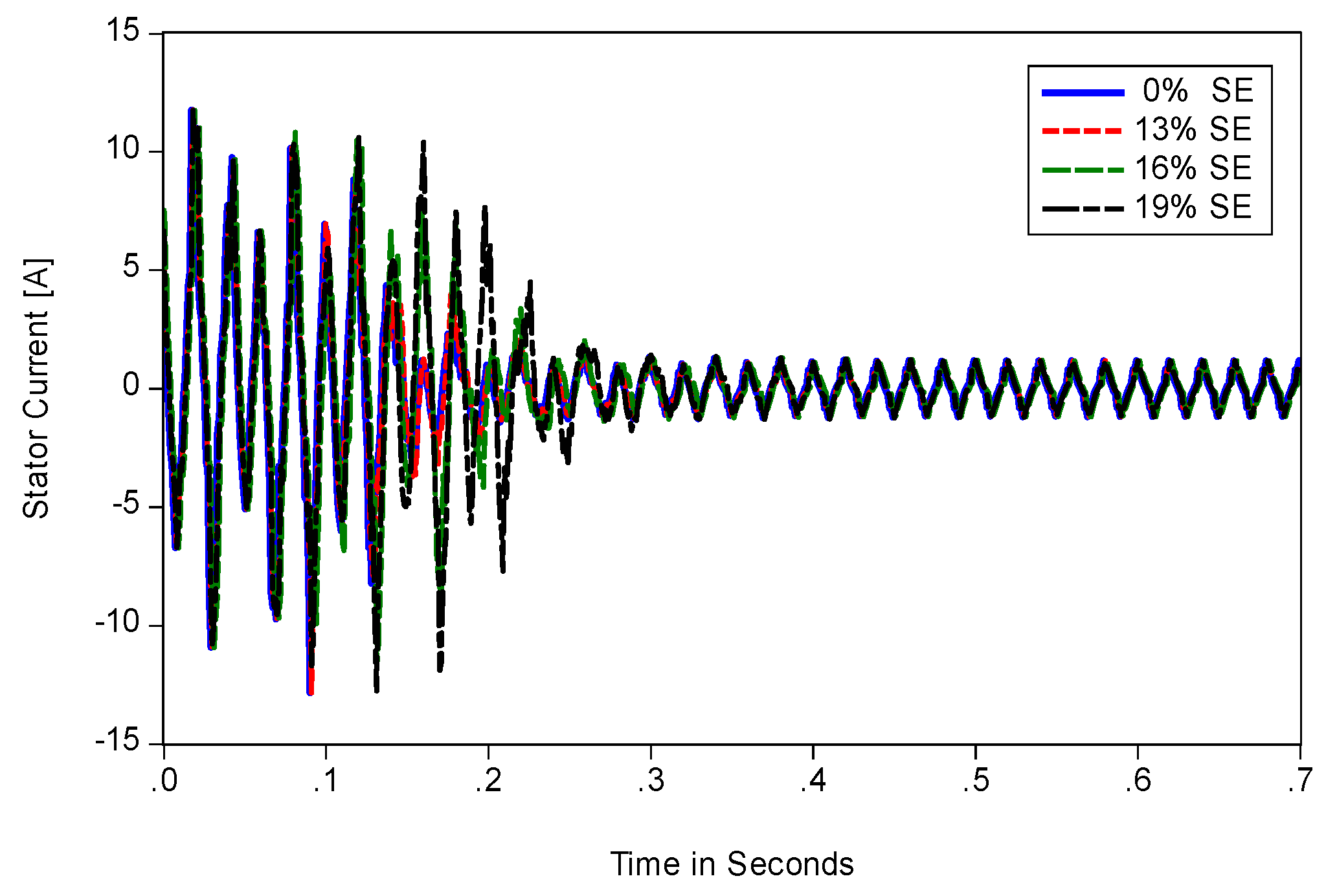
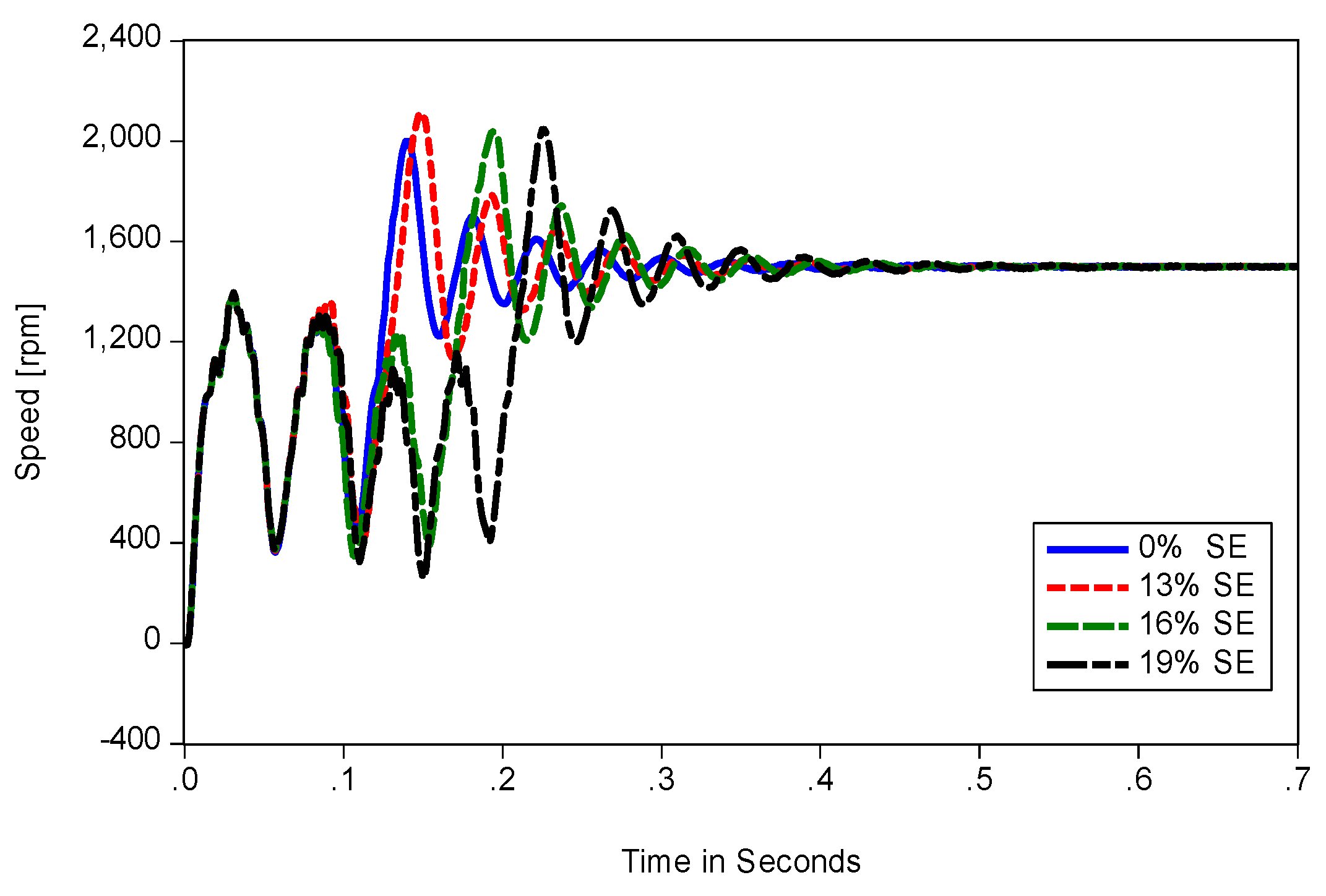
Under different levels of static eccentricity (0% SE, 13% SE, 16% SE, and 19% SE) and a load of 2.1 N·m, the stator current and speed characteristics have different behaviors, Figure 12 and Figure 13. It is clear that as the eccentricity level increases, the synchronization time is also increased. A slight difference is shown in the results between the healthy and 13% static eccentricity condition. However, more peaks, ripples, and longer synchronization times are observed for 16% and 19% static eccentricity before reaching the steady state region.
It is worth mentioning that the use of this accurate mathematical model for developing an online motor current signature diagnostic system can be integrated to the electric utilities and industrial plants predictive maintenance systems in order to run their facilities at high efficiency and to reduce maintenance and failure costs.
Sensitivity analysis is quite important to highlight the main sources of uncertainty and disturbances, which affects the simulation results. As such, and in order to test the robustness and sensitivity of the developed mathematical model, some parameters have been selected and varied. For example, the stator resistance and rotor equivalent resistance values are varied by ±10% of the original parameter value. The simulation is performed for 36 cases, which represent different loading conditions and eccentricity levels. The percentage normalized mean square error (%NMSE) is calculated to show the difference in results corresponding to the original and the modified parameter values. This comparison is conducted for the motor line current characteristic, which is the main output characteristic in this paper. Table 3 presents the percentage NMSE for each simulated case. The results show clearly the robustness of the proposed mathematical model against variation of these motor parameters.
4. Conclusions
This paper proposes a new mathematical and simulation models of LSPMS motor under static eccentricity fault conditions. The simulation is performed to investigate and compare the motor performance under healthy and static eccentricity fault conditions while considering different operating loads. The results obtained for the developed mathematical model under static eccentricity conditions are in good agreement with the FEM simulation results. Besides, results show that the effect of static eccentricity on the stator current depends on the degree of eccentricity, which will affect the motor synchronization time and the time variation of stator current in transient period with less significance on the steady state performance. The results are in good agreement with the findings reported in the literature when using the finite element method. This confirms the precision of the proposed mathematical model for eccentricity conditions. On the other hand, the problem of the eccentricity fault in LSPMS motors is far from being completed by only relying on a limited number of case studies and software packages. Therefore, the analysis could be extended to include the dynamic and mixed eccentricity fault conditions. In addition, the mathematical model can be further improved by considering the nonlinearity between the motor parameters and the output characteristics.
Acknowledgments
This work was supported by the King Abdul-Aziz City for Science and Technology (KACST) through the Science and Technology Unit at the King Fahd University of Petroleum and Minerals (KFUPM) through Project No. 13-ENE403-04 as part of the National Science, Technology and Innovation.
Author Contributions
Ibrahem Hussein did the Matlab code and got simulation results in addition to the paper write-up. Zakariya Al-Hamouz, M. A. Abido and Ibrahem Hussein developed the mathematical model. Abdulaziz Milhem developed the JMAG model and presents its simulation results.
Conflicts of Interest
The authors declare no conflict of interest.
References
- Saidur, R. A review on electrical motors energy use and energy savings. Renew. Sustain. Energy Rev. 2010, 14, 877–898. [Google Scholar] [CrossRef]
- Isfahani, A.H.; Vaez-Zadeh, S. Line start permanent magnet synchronous motors: Challenges and opportunities. Energy 2009, 34, 1755–1763. [Google Scholar] [CrossRef]
- Soreshjani, M.H.; Sadoughi, A. Conceptual comparison of line-start permanent magnet synchronous. J. World Electr. Eng. Technol. 2014, 3, 26–36. [Google Scholar]
- Kahrisangi, M.G.; Isfahani, A.H.; Vaez-Zadeh, S.; Sebdani, M.R. Line-start permanent magnet synchronous motors versus induction motors: A comparative study. Front. Electr. Electron. Eng. 2012, 7, 459–466. [Google Scholar] [CrossRef]
- Fei, W.; Luk, P.; Ma, J.; Shen, J.; Yang, G. A high-performance line-start permanent magnet synchronous motor amended from a small industrial three-phase induction motor. IEEE Trans. Magn. 2009, 45, 4724–4727. [Google Scholar] [CrossRef] [Green Version]
- Behbahanifard, H.; Sadoughi, A. Line start permanent magnet synchronous motor performance and design; a Review. J. World Electr. Eng. Technol. 2015, 4, 58–66. [Google Scholar]
- Kahourzade, S.; Mahmoudi, A.; Hew, W.P. Performance improvement of a line-start permanent-magnet synchronous motor. IEEE Trans. Ind. Electron. 2014. [Google Scholar] [CrossRef]
- Stoia, D.; Cernat, M.; Jimoh, A. Analytical design and analysis of line-start permanent magnet synchronous motors. In Proceedings of the IEEE AFRICON 2009, Nairobi, Kenya, 23–25 September 2009; pp. 1–7. [Google Scholar]
- Toliyat, H.A.; Nandi, S.; Choi, S.; Meshgin-kelk, H. Electric Machines: Modeling Condition Monitoring and Fault Diagnosis; CRC Press Taylor & Francis Group: Boca Raton, FL, USA, 2013. [Google Scholar]
- Henao, H.; Capolino, G.A.; Fernandez-Cabanas, M.; Filippetti, F.; Bruzzese, C.; Strangas, E.; Pusca, R.; Estima, J.; Riera-Guasp, M.; Hedayati-Kia, S. Trends in fault diagnosis for electrical machines: A review of diagnostic techniques. IEEE Ind. Electron. Mag. 2014, 8, 31–42. [Google Scholar] [CrossRef]
- Nandi, S.; Toliyat, H.A.; Li, X. Condition monitoring and fault diagnosis of electrical motors—A review. IEEE Trans. Energy Convers. 2005, 20, 719–729. [Google Scholar] [CrossRef]
- Toliyat, H.A.; Arefeen, M.S.; Parlos, A.G. A method for dynamic simulation of air-gap eccentricity in induction machines. IEEE Trans. Ind. Appl. 1996, 32, 910–918. [Google Scholar] [CrossRef]
- Hooshmandi, H.; Ebrahimi, M.; Davoudi, A.; Pouramin, A. Analytical derivation of induction motors inductances under eccentricity conditions. Prog. Electromagn. Res. B 2014, 60, 95–110. [Google Scholar] [CrossRef]
- Karami, M.; Mariun, N.; Mehrjou, M.R.; Kadir, M.Z.A.A.; Misron, N.; Radzi, M.A.M. Static eccentricity fault recognition in three-phase line start permanent magnet synchronous motor using finite element method. Math. Probl. Eng. 2014, 2014, 132647. [Google Scholar] [CrossRef]
- Ebrahimi, B.M.; Faiz, J.; Javan-Roshtkhari, M.; Nejhad, A.Z. Static eccentricity fault diagnosis in permanent magnet synchronous motor using time stepping finite element method. IEEE Trans. Magn. 2008, 44, 4297–4300. [Google Scholar] [CrossRef]
- Ebrahimi, B.M.; Faiz, J.; Roshtkhari, M.J. Static-, dynamic-, and mixed-eccentricity fault diagnoses in permanent-magnet synchronous motors. IEEE Trans. Ind. Electron. 2009, 56, 4727–4739. [Google Scholar] [CrossRef]
- Faiz, J.; Ebrahim, B.M.; Akin, B.; Toliyat, H.A. Finite-element transient analysis of induction motors under mixed eccentricity fault. IEEE Trans. Magn. 2008, 44, 66–74. [Google Scholar] [CrossRef]
- Goktas, T.; Zafarani, M.; Akin, B. Discernment of broken magnet and static eccentricity faults in permanent magnet synchronous motors. IEEE Trans. Energy Convers. 2016, 31, 578–587. [Google Scholar] [CrossRef]
- Lubin, T.; Hamiti, T.; Razik, H.; Rezzoug, A. Comparison between finite-element analysis and winding function theory for inductances and torque calculation of a synchronous reluctance machine. IEEE Trans. Magn. 2007, 43, 3406–3410. [Google Scholar] [CrossRef]
- Faiz, J.; Tabatabaei, I. Extension of winding function theory for nonuniform air gap in electric machinery. IEEE Trans. Magn. 2002, 38, 3654–3657. [Google Scholar] [CrossRef]
- Serrano-Iribarnegaray, L.; Cruz-Romero, P.; Gomez-Exposito, A. Crirical review of the modified winding function theory. Prog. Electromagn. Res. 2013, 133, 515–534. [Google Scholar] [CrossRef]
- Toliyat, H.A.; Bhattacharya, S.; Rahimian, M.M.; Lipo, T.A. Transient analysis of induction machines under internal faluts using winding functions. In Proceedings of the 3rd International Conference on Electrical Rotating Machines (ELROMA), Bombay, Indian, 15–16 January 1992. [Google Scholar]
- Toliyat, H.A.; Lip, T.A. Transient analysis of cage induction machines under stator, rotor bar and end ring faults. IEEE Trans. Energy Convers. 1995, 10, 241–247. [Google Scholar] [CrossRef]
- Nandi, S.; Ahmed, S.; Toliyat, H.A. Detection of rotor slot and other eccentricity related harmonics in a three phase induction motor with different rotor cages. IEEE Trans. Energy Convers. 2001, 16, 253–260. [Google Scholar] [CrossRef]
- Nandi, S.; Bharadwaj, R.M.; Toliyat, H.A. Mixed eccentricity in three phase induction machines: Analysis, simulation and experiments. In Proceedings of the IEEE Conference Record of the Industry Applications, Pittsburgh, PA, USA, 13–18 October 2002; pp. 1525–1532. [Google Scholar]
- Ghazvini, E.; Faiz, J.; Tabatabaei-Ardekani, I.; Shirani, A. Modeling and dynamic simulation of induction machine under mixed eccentricity conditions using winding function. In CIGRÉ 2004 Session; CIGRE: Paris, France, 2004. [Google Scholar]
- Wu, L.W.L.; Habetler, T.G.; Harley, R.G. Separating load torque oscillation and rotor faults in stator current based-induction motor condition monitoring. In Proceedings of the 2005 IEEE International Conference on Electric Machines and Drives, San Antonio, TX, USA, 15–18 May 2005; pp. 1889–1894. [Google Scholar]
- Ebrahimi, B.M.; Etemadrezaei, M.; Faiz, J. Dynamic eccentricity fault diagnosis in round rotor synchronous motors. Energy Convers. Manag. 2011, 52, 2092–2097. [Google Scholar] [CrossRef]
- Ebrahimi, B.; Jawad, F.; Mohammad, E.; Mojtaba, B. Eccentricity fault identification in round rotor synchronous motors considering load variation. Prz. Elektrotech. 2011, 87, 288–292. [Google Scholar]
- Al-Nuaim, N.A.; Toliyat, H. A novel method for modeling dynamic air-gap eccentricity in synchronous machines based on modified winding function theory. IEEE Trans. Energy Convers. 1998, 13, 156–162. [Google Scholar] [CrossRef]
- Wymeersch, B.; de Belie, F.; Rasmussen, C.B.; Jensen, F.; Vandevelde, L. Mutual-inductance modelling in line-start permanent-magnet synchronous machines based on winding-function theory. In Proceedings of the 2013 IEEE International Electric Machines and Drives Conference (IEMDC), Chicago, IL, USA, 12–15 May 2013; pp. 607–611. [Google Scholar]
- Karami, M.; Mariun, N.; Mehrjou, M.R.; Kadir, M.Z.A.A.; Misron, N.; Radzi, M.A.M. Diagnosis of static eccentricity fault in line start permanent magnet synchronous motor. In Proceedings of the 2014 IEEE International Conference on Power and Energy, Kuching Sarawak, Malaysia, 1–3 December 2014; pp. 83–86. [Google Scholar]
- Moustafa, M.; Sedky, M. Diagnosis of static, dynamic and mixed eccentricity in line start permanent magnet synchronous motor by using FEM. Int. J. Electr. Robot. Electron. Commun. Eng. 2014, 8, 29–34. [Google Scholar]
- Ong, C. Dynamic Simulation of Electric Machinery Using Matlab-Simulink, 1st ed.; Prentice Hall PTR: Upper Saddle River, NJ, USA, 1998. [Google Scholar]
- Krause, P.C.; Wasynczuk, O.; Sundhoff, S.D. Analysis of Electrical Machinery and Drive Systems, 2nd ed.; Wily-IEEE Press: Hoboken, NJ, USA, 2002. [Google Scholar]
- Tabatabaei, I.; Faiz, J.; Lesani, H. Modeling and Simulation of a Salient-Pole Using Modified Winding Function Theory. IEEE Trans. Magn. 2004, 40, 1550–1555. [Google Scholar] [CrossRef]
- Hamdani, S.; Touhami, O.; Ibtiouen, R.; Hasni, M. Analytical evaluation of inductances for induction machine with dynamic eccentricity using MWFA and FE methods. In Proceedings of the 2013 IEEE International Symposium on Diagnostics for Electric Machines, Power Electronics and Drives (SDEMPED), Valencia, Spain, 27–30 August 2013; pp. 420–427. [Google Scholar]
Figure 1.
Stator and rotor circuits of Line-Start Permanent Magnet Synchronous (LSPMS) motor.

Figure 2.
Motor geometry with static eccentricity.

Figure 3.
Interior-mount LSPMSM.

Figure 4.
Two-dimensional (2-D) geometry model parts of LSPMS motor.

Figure 5.
2-D mesh model of LSPMS motor.

Figure 6.
Flow chart of simulation process using. MATLAB®.

Figure 7.
Stator Current at 1.5 N·m load.

Figure 8.
Electromagnetic torque at 1.5 N·m load.

Figure 9.
Speed at 1.5 N·m load.

Figure 10.
Stator Current for a load of 2.1 N·m and 19% eccentricity.

Figure 11.
Stator current for healthy and 19% eccentricity.

Figure 12.
Stator Current under different values of static eccentricity (SE).

Figure 13.
Speed under different values of SE.


Table 1.
LSPMS Motor Specifications.
| Parameter | Value |
|---|---|
| Rated power (W) | 750 |
| Rated Voltage (V) | 415 |
| Stator phase resistance (Ohm) | 19.15 |
| Stator leakage inductance (mH) | 0.004 |
| Number of poles | 4 |
| Frequency (Hz) | 50 |
| Air-gap length (mm) | 0.3 |
| Outer/inner stator diameter (mm) | 120/75 |
| Number of stator/rotor slots | 24/16 |
| Axial length of stator core (mm) | 75 |
| Number of turns per slot | 139 |
| Height of stator yoke (mm) | 45 |
| Height of stator/rotor slots (mm) | 13/9.5 |
| Magnet material | Recoma-24HE |
| Remanent of magnet (T) | 1.02 |
Table 2.
The percentage correlation and normalized mean square error (NMSE) of simulated cases.
| Case Number | Load N·m | % | %Correlation | %NMSE |
|---|---|---|---|---|
| Case 1 | 0 | 0 | 82.3 | 0.8 |
| Case 2 | 16 | 83.1 | 0.7 | |
| Case 3 | 1.5 | 0 | 81.5 | 2.1 |
| Case 4 | 16 | 83.7 | 2.0 | |
| Case 5 | 22 | 80.3 | 2.3 | |
| Case 6 | 2 | 0 | 81.6 | 2.4 |
| Case 7 | 16 | 80.0 | 2.4 | |
| Case 8 | 2.1 | 0 | 76.0 | 2.6 |
| Case 9 | 13 | 76.3 | 3.1 | |
| Case 10 | 19 | 75.0 | 3.5 | |
| Case 11 | 30 | 76.2 | 3.2 | |
| Case 12 | 2.2 | 0 | 77.4 | 3.2 |
| Case 13 | 13 | 76.8 | 3.1 | |
| Case 14 | 16 | 76.0 | 3.8 | |
| Case 15 | 2.3 | 0 | 80.1 | 3.2 |
| Case 16 | 18 | 74.1 | 4.1 | |
| Case 17 | 30 | 79.0 | 3.4 | |
| Case 18 | 33 | 77.1 | 3.7 | |
| Case 19 | 2.4 | 0 | 75.0 | 3.5 |
| Case 20 | 16 | 74.0 | 4.1 | |
| Case 21 | 33 | 76.0 | 3.2 |
Table 3.
The percentage NMSE of simulated cases.
| Eccentricity Percentage | %NMSE | ||||||||
|---|---|---|---|---|---|---|---|---|---|
| Under Healthy state () | Under | Under | |||||||
| Load Parameter | 0 N·m | 1.5 N·m | 2.4 N·m | 0 N·m | 1.5 N·m | 2.4 N·m | 0 N·m | 1.5 N·m | 2.4 N·m |
| 0.20 | 2.03 | 4.62 | 0.99 | 2.70 | 4.43 | 0.99 | 2.63 | 4.39 | |
| 0.65 | 1.47 | 3.28 | 0.24 | 2.25 | 2.45 | 1.24 | 2.49 | 9.40 | |
| 1.50 | 2.93 | 10.00 | 0.76 | 3.03 | 11.48 | 1.18 | 3.67 | 18.55 | |
| 2.59 | 2.81 | 10.31 | 1.76 | 3.79 | 11.45 | 1.15 | 3.35 | 13.71 | |
© 2018 by the authors. Licensee MDPI, Basel, Switzerland. This article is an open access article distributed under the terms and conditions of the Creative Commons Attribution (CC BY) license (http://creativecommons.org/licenses/by/4.0/).
Share and Cite
MDPI and ACS Style
Hussein, I.; Al-Hamouz, Z.; Abido, M.A.; Milhem, A. On the Mathematical Modeling of Line-Start Permanent Magnet Synchronous Motors under Static Eccentricity. Energies 2018, 11, 197. https://0-doi-org.brum.beds.ac.uk/10.3390/en11010197
AMA Style
Hussein I, Al-Hamouz Z, Abido MA, Milhem A. On the Mathematical Modeling of Line-Start Permanent Magnet Synchronous Motors under Static Eccentricity. Energies. 2018; 11(1):197. https://0-doi-org.brum.beds.ac.uk/10.3390/en11010197
Chicago/Turabian StyleHussein, Ibrahem, Zakariya Al-Hamouz, M. A. Abido, and Abdulaziz Milhem. 2018. "On the Mathematical Modeling of Line-Start Permanent Magnet Synchronous Motors under Static Eccentricity" Energies 11, no. 1: 197. https://0-doi-org.brum.beds.ac.uk/10.3390/en11010197
Note that from the first issue of 2016, this journal uses article numbers instead of page numbers. See further details here.