Article

Lyapunov Stability and Performance Analysis of the Fractional Order Sliding Mode Control for a Parallel Connected UPS System under Unbalanced and Nonlinear Load Conditions

Department of Electrical Engineering, Bahria University, Islamabad 44000, Pakistan
*
Author to whom correspondence should be addressed.
Submission received: 11 October 2018 / Revised: 12 November 2018 / Accepted: 13 November 2018 / Published: 13 December 2018
(This article belongs to the Section F: Electrical Engineering)

Abstract

:
Parallel-connected uninterruptible power supply (UPS) systems have been used to maintain power supply to the critical load in order to increase power capacity and system reliability. This paper presents a robust and precise voltage control strategy for parallel-connected UPS systems. Each parallel-connected UPS system consists of a three-phase inverter with an output inductor-capacitor (LC) filter directly connected to an AC common bus in order to feed the critical load. Fractional-order sliding mode control (FOSMC) is proposed to maintain the quality of the output voltage despite linear, unbalanced and/or nonlinear load condition. The Riemann-Liouville (RL) fractional derivative is employed in designing the sliding surface. The voltage control strategy effectively eliminates the parametric uncertainties, external disturbances, and reduce the total harmonic distortion (THD) of the output voltage. Furthermore, it also maintains very good voltage regulation such as dynamic response and steady-state error under the nonlinear or unbalanced load conditions. The stability of the proposed controller is proven by applying Lyapunov stability theory. Droop control approach and virtual output impedance (VOI) loop are investigated to guarantee the accurate active and reactive power-sharing for parallel-connected UPS system. Finally, the implementation of the control scheme is carried out by using MATLAB/Simulink real-time environment.

1. Introduction

The increasing demands for sustainable, clean, and environmentally friendly energy call for distributed renewable energy resources to frequently be used to support electricity demand. In an electric system, the critical safety-related loads require extremely reliable and high-quality power to function efficiently. Uninterruptible Power Supplies (UPSs) play a key role to provide a continuous power supply and protection against interruptions. When a power outage takes place, a UPS must deliver an emergency backup power to a load and prevent damages. Typically, an ideal UPS provides unity power factor, low Total Harmonic Distortion (THD) sinusoidal, high efficiency, low cost, high reliability, electric isolation, and low transients response time during the transition from grid mode to backup mode and vice versa. Besides, the most important task of UPS is to maintain the pure sinusoidal output voltage with low THD under linear and distorted load conditions. According to the standards of Institute of Electrical and Electronics Engineers (IEEE) 519–1992, the maximum THD of the output voltage in the UPS system should be less than 5% in common applications such as households’ appliances and offices. Similarly, for sensitive applications like safety devices, and airport apparatus, the THD should be less than 3%. The configuration of the UPS system is mainly categorized as off-line or line-preferred, on-line or inverter-preferred and line-interactive UPS system [1,2].
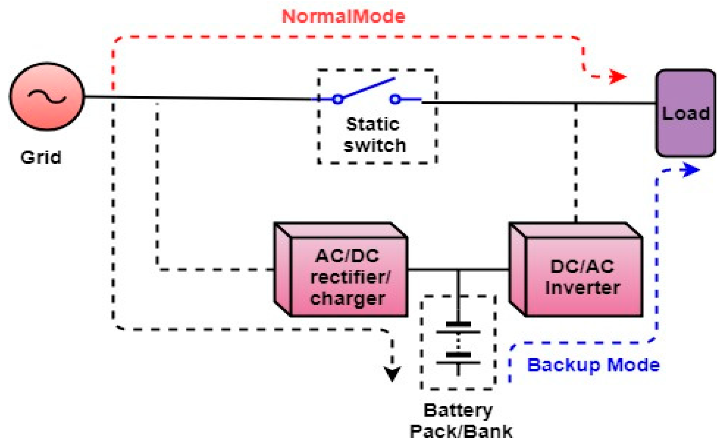
The configuration of a typical off-line UPS system is shown in Figure 1. It usually consists of a static transfer switch, AC/DC rectifier/charger, DC/AC inverter, DC link interface, and a battery pack. The static switch connects the load to the AC grid and the battery pack charges through AC/DC rectifier/charger under normal power condition. When the grid fails, an abnormal power condition occurs, the static switch disconnects the load from the grid and the DC/AC inverter regulates power from the battery pack to the load for the period till the utility grid is back again. This topology offers some advantages such as high efficiency, simple design, passive line conditioning, cheaper, and small size. However, the major disadvantages associated with this configuration are slow transition response from the AC grid to the backup mode, lack of isolation between the load and AC line, and no output voltage regulation.
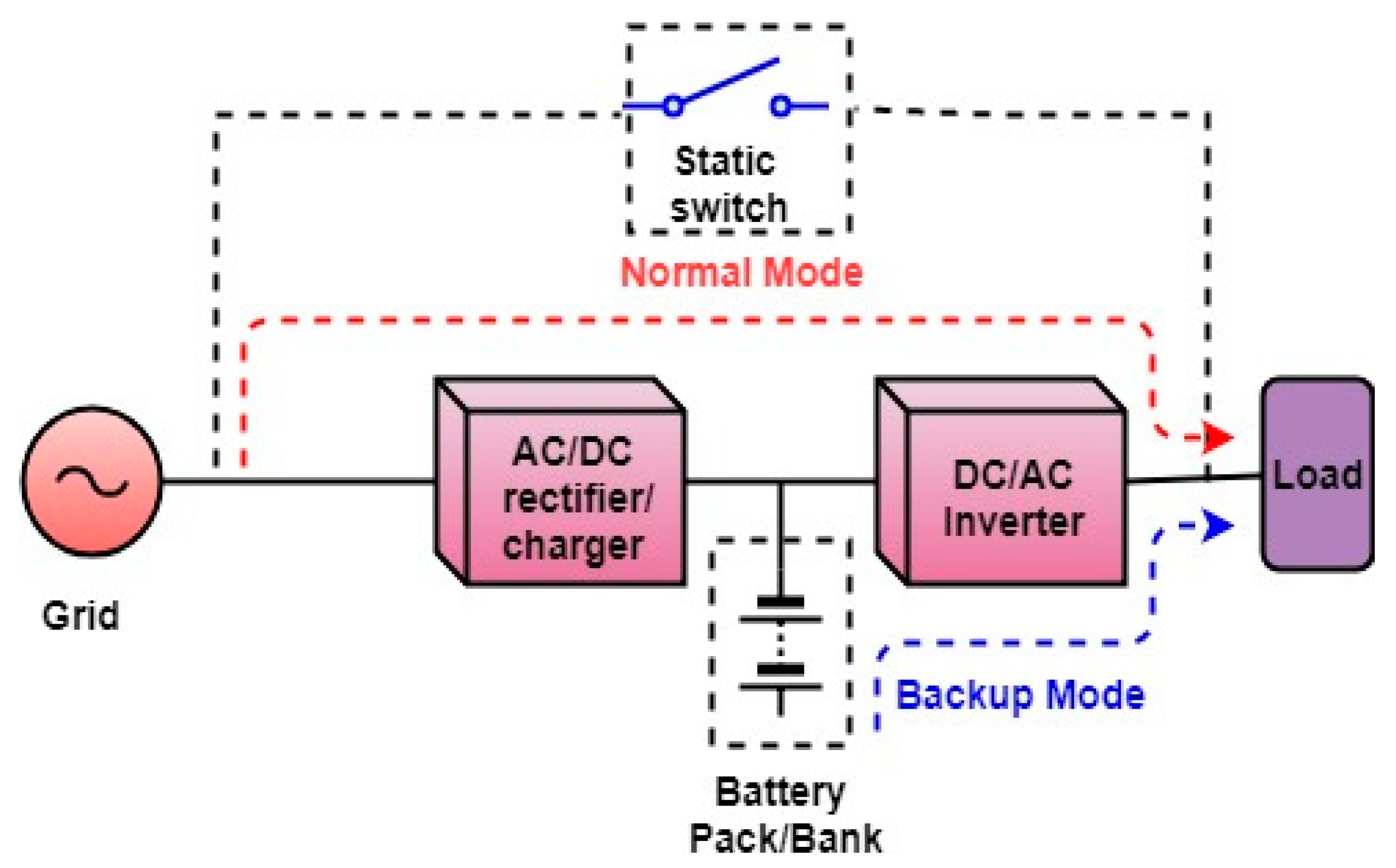
Likewise, the off-line UPS system, the on-line UPS system is the popular and most used configuration. It consists of an AC/DC rectifier charger, static transfer switch (bypass), a battery pack and a DC/AC inverter. The block diagram of the classical on-line UPS system is shown in Figure 2. In this configuration, the power continuously provides to the load through the rectifier charger and inverter under both normal and abnormal AC grid power conditions. During normal operation the battery pack charges while in case of AC grid power outage, the battery pack discharges and supply full power to the load without utilizing the static switch. The inverter is connected in series with the load. Hence, during the transition from normal mode to the backup mode, the transfer time is zero. In this configuration, the inverter is the main powering path for the load instead of the AC grid. This topology provides advantages such as good powering conditioning, load protection, high power rating, and accurate power regulation for the load. The main drawbacks associated with this topology include low power factor, high cost, low efficiency because of the double stages of power conversion, and large size.
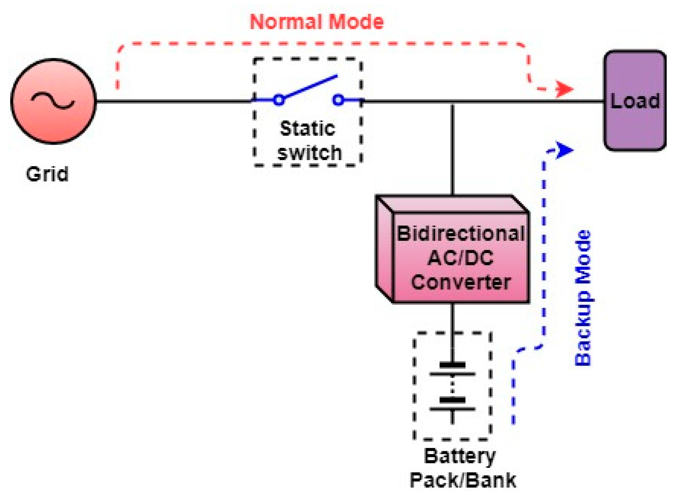
The next topology is the line-interactive UPS system. The components include the static transfer switch, a bidirectional converter, a series inductor, and a battery pack. Technically, this UPS system can work in either mode as standby UPS and as an on-line UPS (series configuration). The series inductor is not necessary for standby line-interactive UPS system. However, in order to enhance both the voltage regulation and power factor of the load, most of the line-interactive UPS system operate on-line.
The classical configuration is shown in Figure 3. While under a normal mode of operation, the bidirectional converter charges the battery pack and the AC grid provides power to the load. In the case of AC grid failure, the static transfer switch isolates the load from the AC grid and the power to the load provides through the bidirectional converter. The main benefits of this configuration are a simple design, more reliable, high efficiency, small size, good harmonics suppression for the input current, and cheaper. The major drawback is that it does not offer any voltage regulation of the load during normal condition.
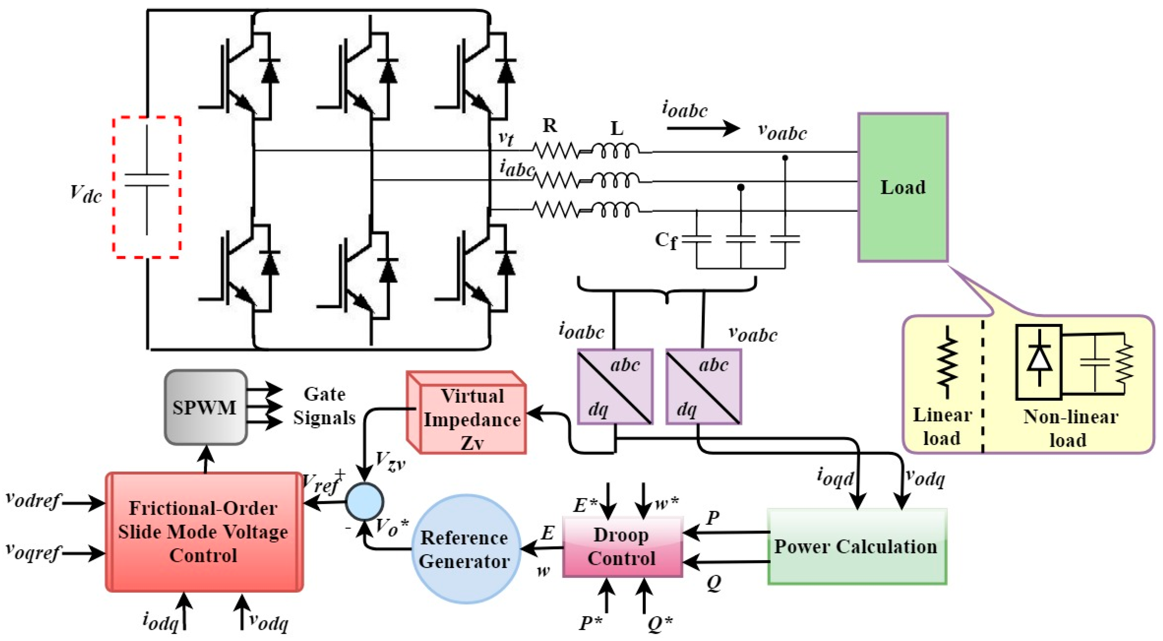
The UPS system is mainly composed of a voltage-source inverter (VSI) and an output LC filter. Generally, the UPS system performance is influenced by the output filters of the three-phase inverter which are tuned to remove fixed harmonic frequency components. Moreover, the majority of loads supply by UPS systems are unbalanced and/or nonlinear loads. Nonlinear currents drawn by unbalanced and nonlinear loads distort the output voltage of UPS system which leads to high current flow, excessive losses, heating, and malfunctioning of the critical loads. Therefore, the designing of a high-quality three-phase inverter for UPS applications are necessary in order to achieve a pure sinusoidal voltage with low THD and fast transient response during load step variations. Considering the aforementioned issues, many advanced control strategies for UPS systems are proposed in the literature to address the voltage quality enhancement. In [3,4], conventional multi-feedback loop hybrid proportional-integral-derivative (PID) control strategies have been proposed. Both the schemes provide a very good dynamic performance and simple implementation. However, as neither the inductor current nor the load current is considered, if any abnormality occurs on the load side, these schemes cannot guarantee the safe and stable operation of the system. Regarding the three-phase UPS system, the Proportional Resonant (PR) controller in the stationary reference frame has been used to supply nonlinear and unbalanced loads in [5]. This controller reduces THD of the output voltage, eliminate steady-state error, and fast dynamic response. However, in order to attenuate the lower order harmonics, the output filter inductance (L, LC, LCL etc.) values are very large which increases the size and cost of the system.
Nowadays, nonlinear control techniques have gained considerable attention from researchers because these techniques offer some advantages like robustness, less sensitive to external disturbances, and fast dynamic performance. In [6], deadbeat control has been proposed in order to enhance the closed-loop performance of the pulse width modulation (PWM) inverter. Deadbeat control technique provides some advantages such as fast dynamic response, and good performance under a linear load. However, this controller is highly sensitive to parameters changes, model uncertainties, measurement noise, and sometimes to switching frequency. In order to overcome the aforementioned issues, Observer-based deadbeat controllers have been proposed in [7,8]. Though, there is a trade-off between the controller stability margin and the closed-loop performance. In [9,10], the Repetitive controller (RC) for UPS inverters are investigated so as to compensate the unbalance and harmonic distortion. This controller provides a good regulation for distorted loads, eliminate a periodical tracking error and excellent harmonics (both odd and even components) rejection capability. However, the dynamic response is quite slow, thus RC is usually escorted by robust controllers for enhanced dynamics response time of the controller. Additionally, high memory usage which imposes a high computational burden is an extra drawback in the RC controller. Iterative Learning Control (ILC) for UPS inverters is suggested in [11]. This technique is capable of achieving high performance. However, the design is complex and also the switching frequency is very high, which result in huge switching losses. The Model Predictive Control (MPC) techniques are proposed in [12,13,14,15,16] which provide a simple structure and good dynamic performance. A cost function is obtained to predict the next switching state. Also, MPC has the ability to manipulate different constraints like switching frequency minimization. However, the predictive control requires accurate system parameters to reach the desired performance. Further, it is difficult to implement the MPC technique as the cost function calculation compel high computational burden. In [17], a robust control technique for VSC is suggested to compensate the harmonics in the islanded mode of operation. The controller eliminates the system uncertainties and maintains pure sinusoidal three-phase voltage under unbalanced/nonlinear load current conditions. A robust H 2 / H voltage control strategy for islanded microgrid is addressed in [18]. The droop control and power management system provide the nominal values of voltage and frequency. Additionally, the nonlinear robust H 2 / H technique provide the ride-through capability, guarantee power-sharing, eliminate small and large signal disturbances, and enhance the performance under nonlinear loads.
Sliding mode control (SMC) is a nonlinear and variable structure control technique has gained a huge interest from the researchers due to its inherent characteristics of simple implementation, strong robustness, good tracking of current reference, excellent dynamic response, high accuracy, and insensitivity to external disturbances and parameter uncertainties. Considering the abovementioned qualities, SMC is extremely suitable for the voltage-source converter (VSC) and can deal effectively with the nonlinear behavior of the power converter. The main problem of SMC is the chattering phenomena because of very high switching frequency result in excessive power losses, electro-magnetic noises, low control accuracy, and problems in the output filter design.
For single and three-phase inverters, SMC is addressed in [2,19,20,21] and [22,23]. The chattering phenomena are attenuated in [19,21] and [23] by smoothing the feedback control law in a narrow boundary layer and the switching function. Also, accomplishing a fixed switching frequency variable hysteresis band comparator. However, the robustness and the reference tracking error of these schemes is nearly degraded. In [24], Particle Swarm Optimization (PSO) for tuning control gains of terminal SMC with a fuzzy estimator of UPS inverter is proposed. This technique provides good dynamic response and improves the performance of the UPS inverter under the transient loading conditions. But, the THD level at the output voltage is high and also this technique cannot eliminate circulating currents. An Adaptive SMC technique with an auto-tuning idea of the sliding switching gain for a three-phase UPS system is recommended in [25]. This technique eliminates chattering phenomena to a great extent and also minimize sliding switching gain without considering the system uncertainties and external perturbations. Nevertheless, the response time is relatively slow, hence, this may encounter a serious stability issue. Nowadays, the decentralized SMC strategies [26,27] have been addressed to enhance the system stability and provide the robustness under unknown load condition. Two separate SMC controllers are designed for hybrid microgrid such as for fundamental positive sequence, direct power SMC scheme is used and for the negative sequence, an SMC current scheme is adopted. The controller ensures the power-sharing, regulate active and reactive powers, and mitigate the current harmonics under unbalanced and nonlinear load current conditions in grid-tied mode and also regulate voltage and frequency in islanded mode.
In the feedback control theory, fractional calculus is the newly emerging concept which deals with the fractional-order derivatives and integrals. In fact, the primary difference between fractional-order derivative and integer-order derivative mainly comprises of two aspects. Firstly, integer-order derivative depicts certain attributes like variation, uncertainties etc. of a physical or mechanical process at a particular instant of time, whereas, in the fractional-order derivative, the entire time domain is considered. Secondly, integer order derivative evaluates a physical process at a certain position within its local domain while on the other hand, fractional order considers the whole space for evaluation. Traditional SMC does not guarantee the convergence of the system. Moreover, chattering phenomena also exist which is not desired. In contrast to classical SMC, the fractional-order sliding mode control (FOSMC) control is an effective method to alleviate chattering phenomena and provides a more flexible degree of freedom [28]. The Riemann-Liouville (RL) fractional derivative is used in designing the sliding surface, and the upgraded exponential law is exploited so as to alleviate the chattering phenomena and to bring and keep the state variable onto the sliding surface. Moreover, to the best of the authors’ knowledge, the behavior of FOSMC for parallel-connected UPS system has not been examined so far, hence to accomplish this research gap, this paper presents nonlinear voltage control strategy based on FOSMC for parallel operating UPS system.
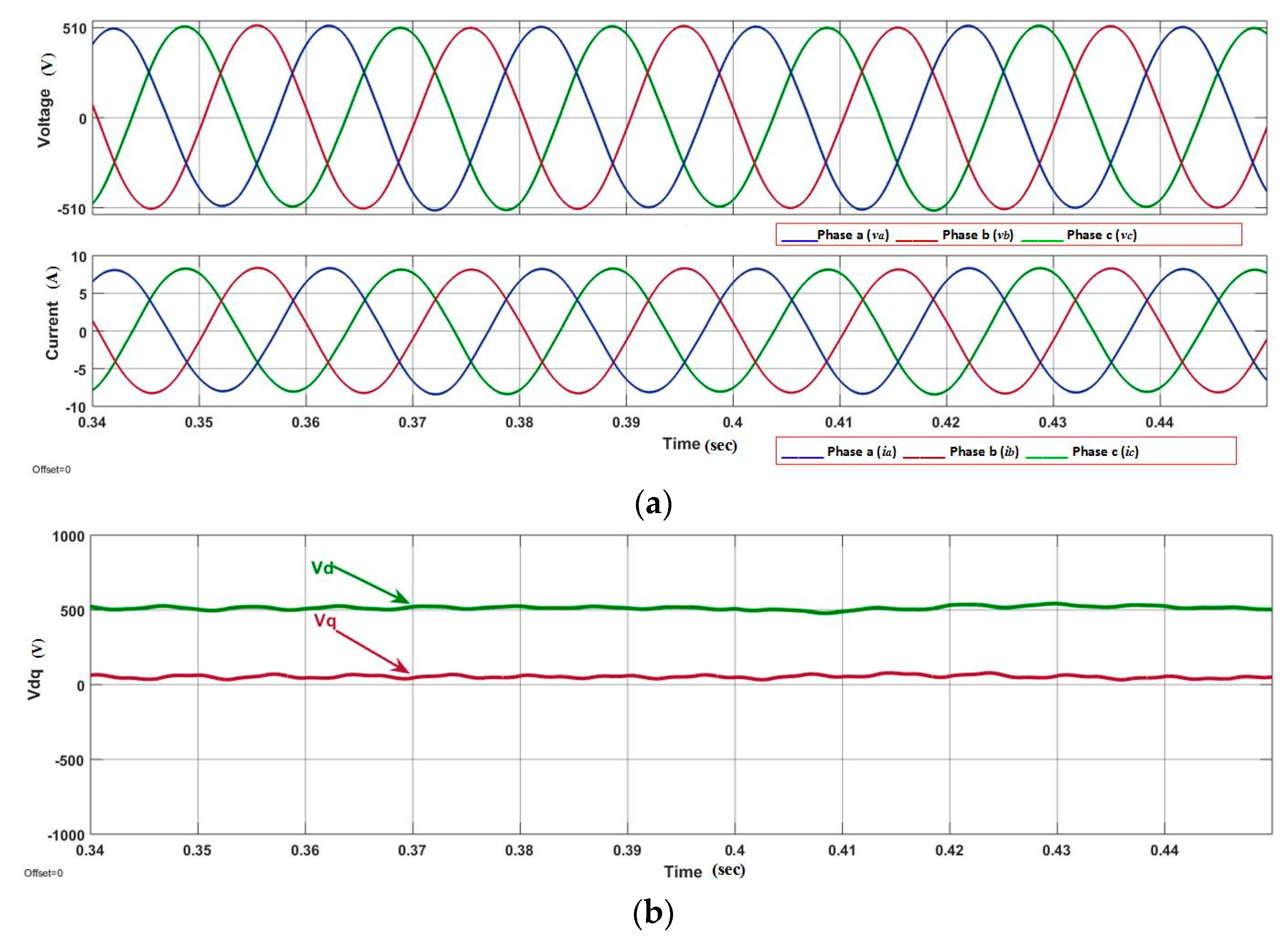
This paper presents a nonlinear control strategy for the voltage control of the parallel-connected UPS system. FOSMC scheme maintains the quality of the output voltage under multiple balanced/unbalanced dynamic load and also under distorted load current condition. Moreover, the proposed control strategy utilized fewer voltage sensors compared to model predictive control and classical SMC methods. A Lyapunov stability theorem is used to prove the stability of the proposed controller. Droop control is designed for the parallel-connected UPS systems to ensure proper power-sharing. Real-time simulation is performed in MATLAB/Simulink to show robustness and precise performance of the controller to maintain system power quality despite linear and/or distorted load current conditions. Additionally, the virtual output impedance loop is designed for the accurate reactive power-sharing with the load. The performance of the proposed FOSMC is compared with conventional proportional integral (PI) controller, and the simulation results show the THD of the output voltage of 0.40% and 1.03% for FOSMC, and 1.82% and 6.84% for PI controller under linear and nonlinear load, respectively.
The paper is organized as follows: 
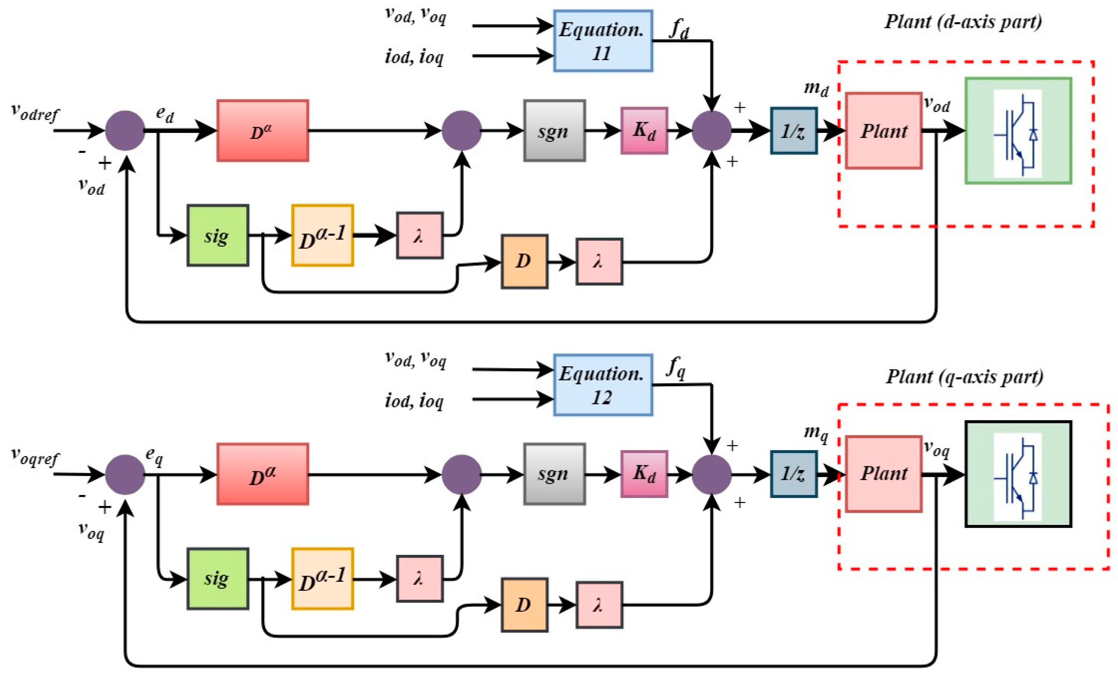
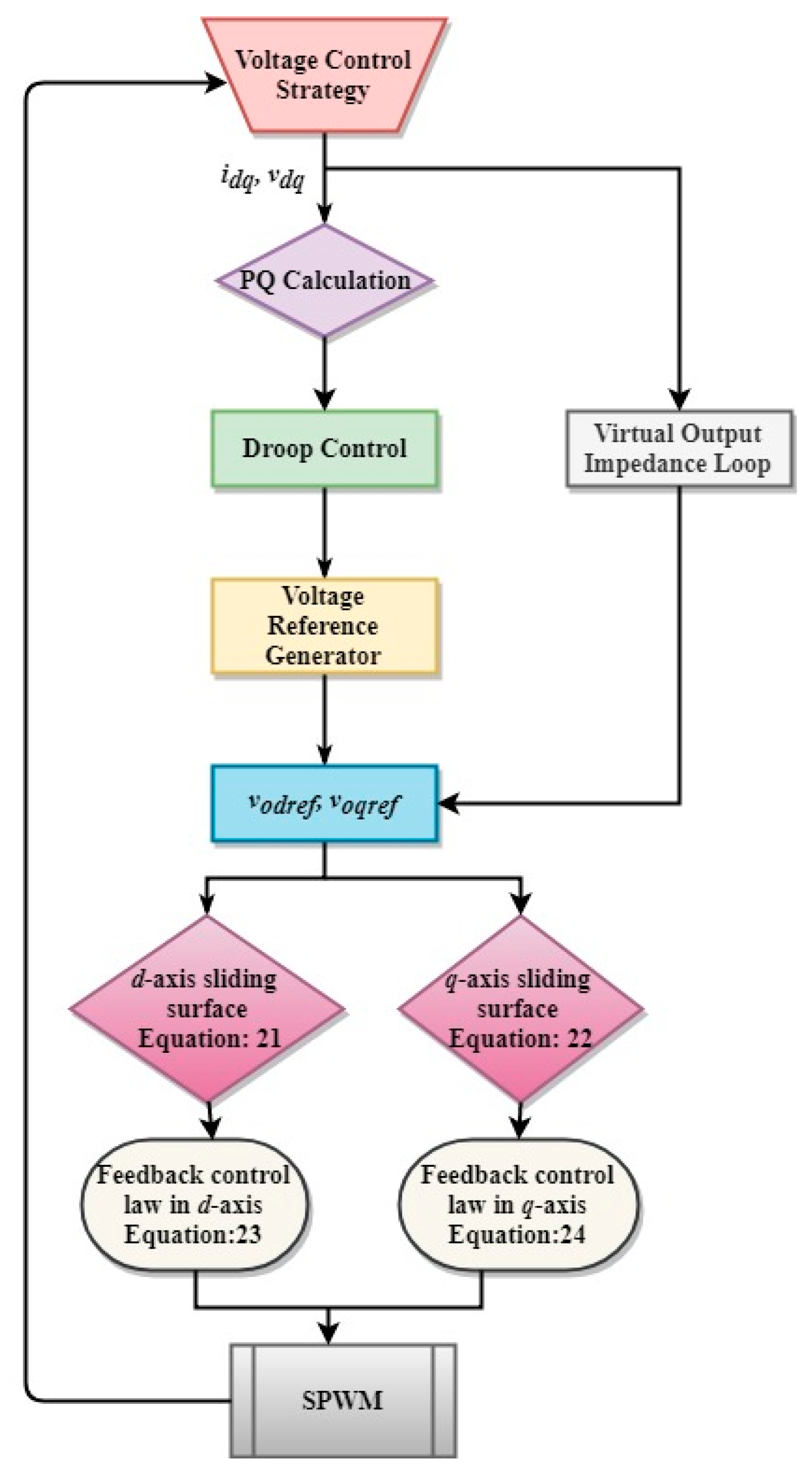
Section 2 describes the system description, dynamic model of the inverter, and the mathematical model of the FOSMC such as the design of the sliding surface and feedback control law. Section 3 represents the Lyapunov stability theorem. 
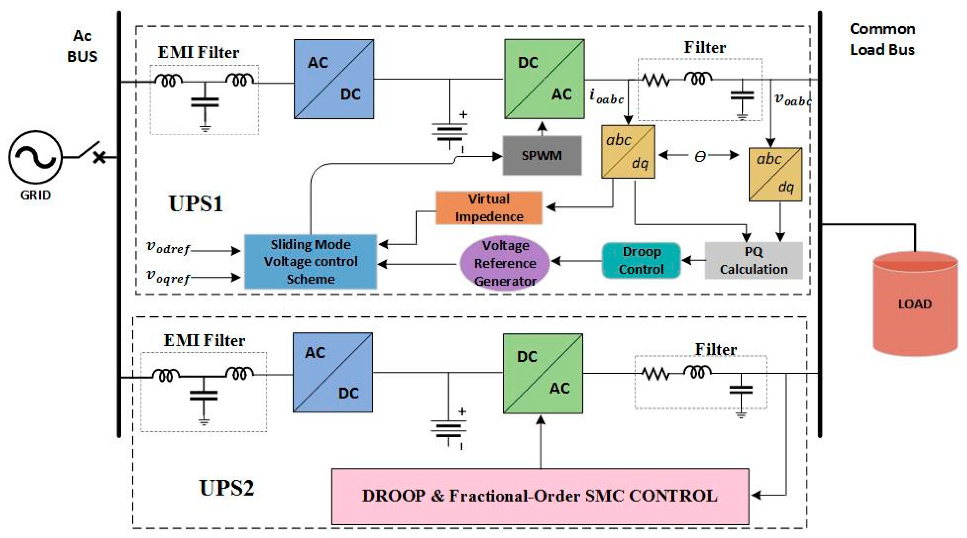
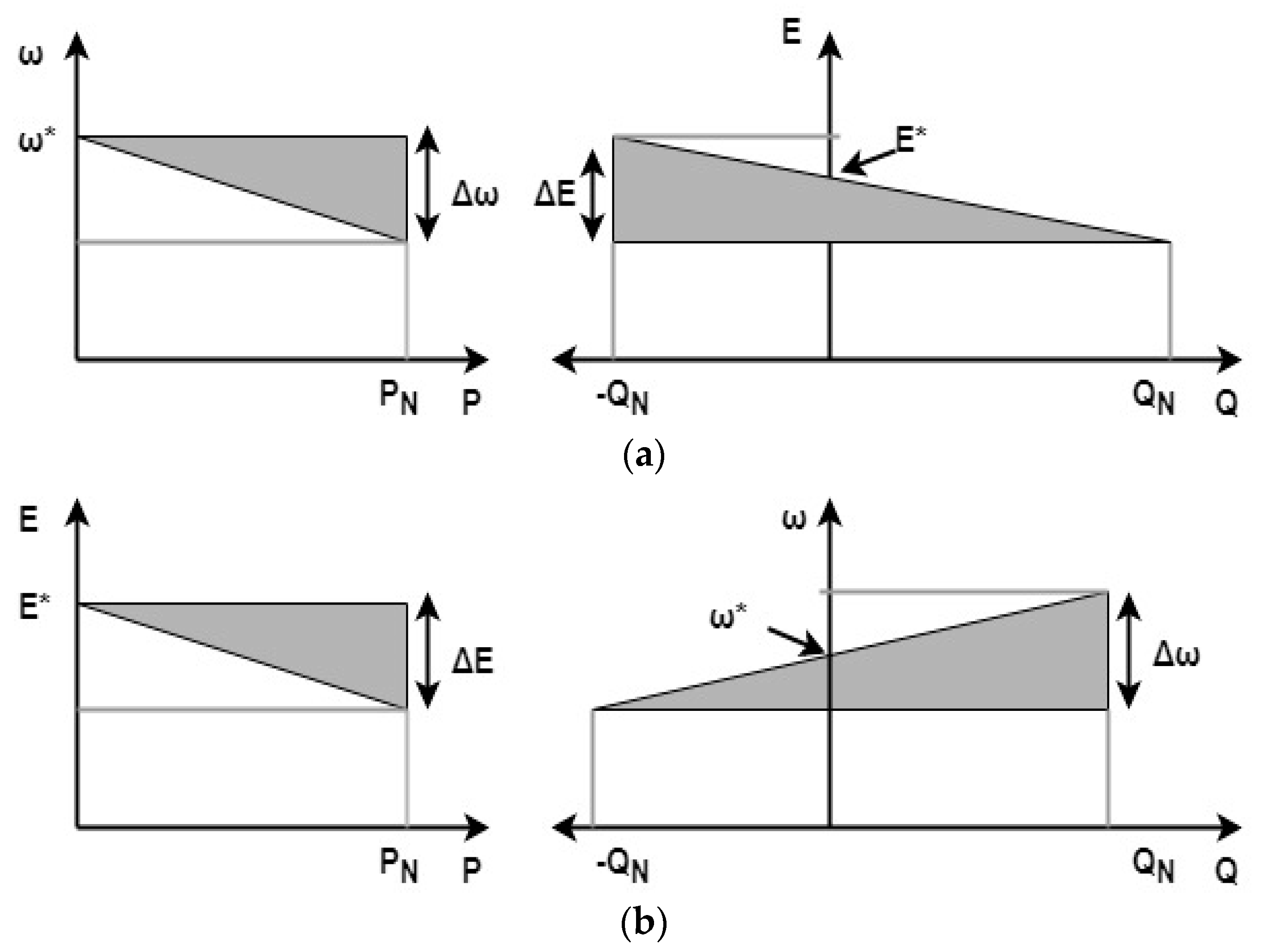
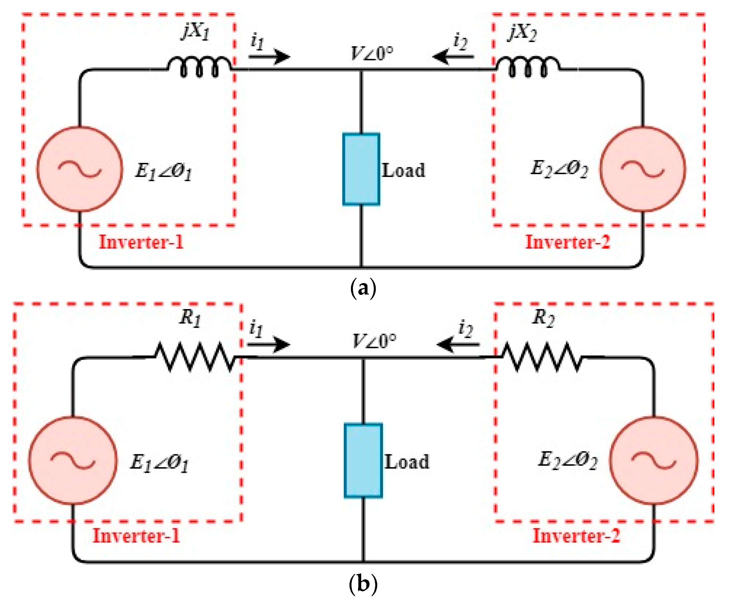
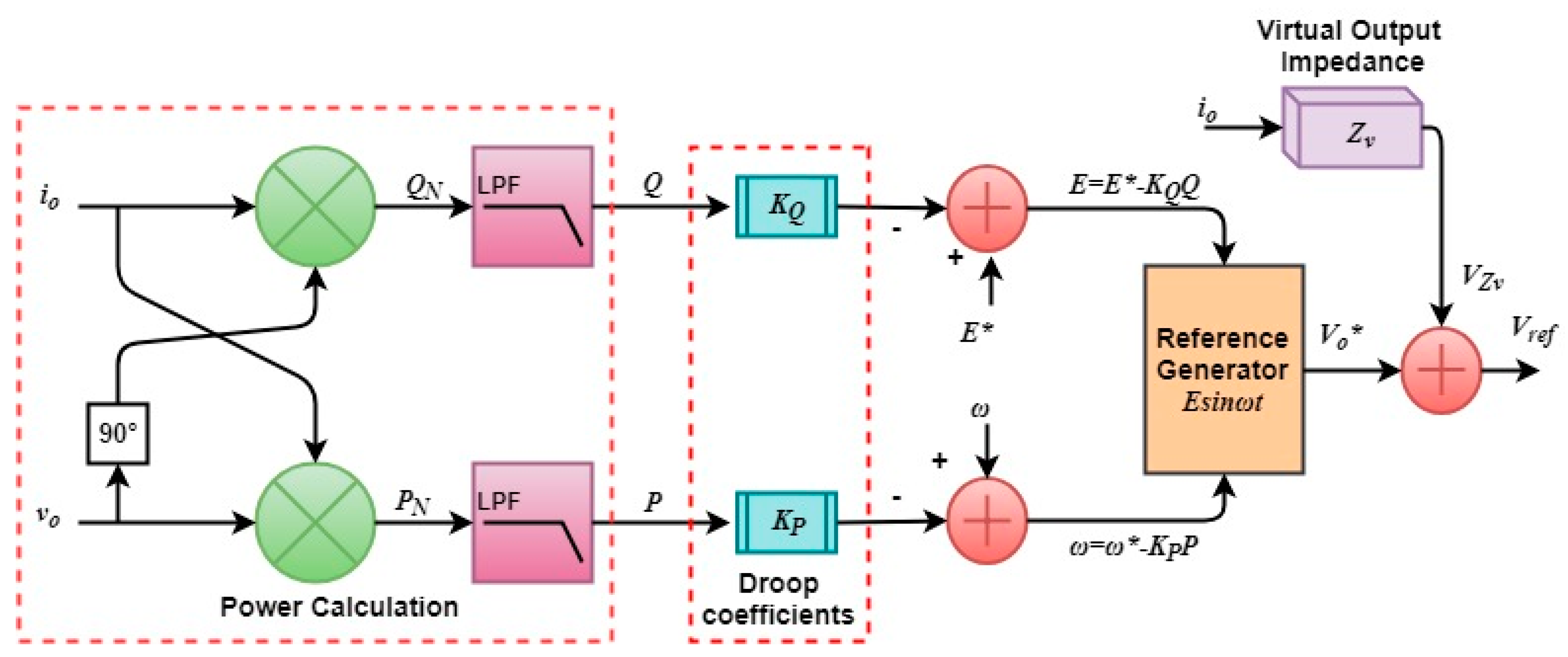
Section 4 presents the parallel UPS system and droop control explanation. 
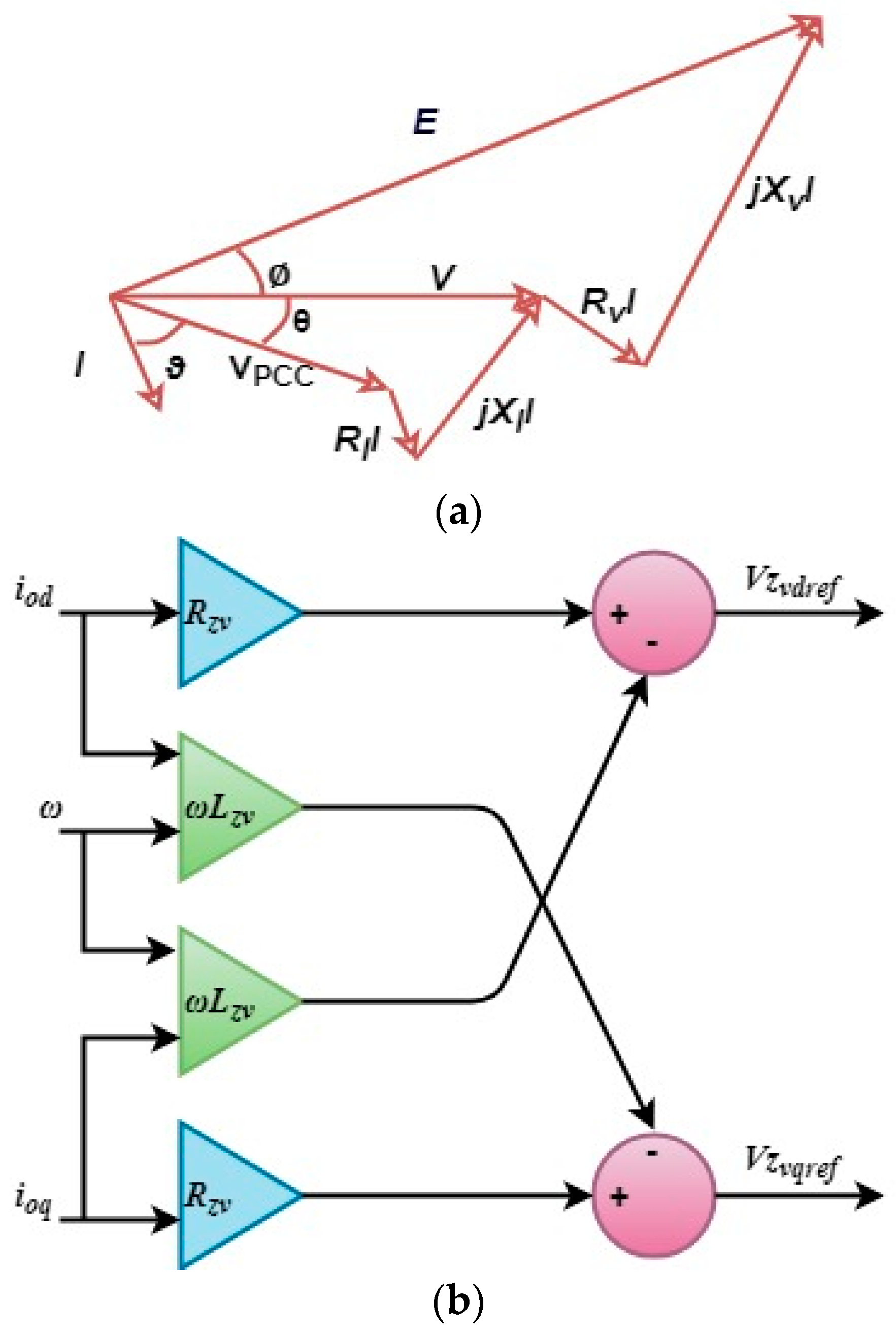
Section 5 explains the virtual output impedance (VOI). Then, Section 6 demonstrates the simulation results and detail comparison between FOSM and the conventional PI controller. Finally, discussions and conclusion are stated in Section 7 and Section 8, respectively.

2. System Description

The circuit and control diagram of the three-phase UPS system is shown in Figure 4. It consists of three-phase VSI connected to load through output LC filter, where L, R and C f are the inductance, resistance, and capacitance, respectively of the output LC filter. v tabc and v oabc are the three-phase output terminal voltages of the inverter and the AC bus or capacitor voltage, respectively. The voltage and current of the output filter are obtained in a sinusoidal dq reference frame, where the subscripts d and q represent the direct axis (d-axis) and quadrature axis (q-axis) of corresponding variables.
The dynamic model of the inverter can be obtained as:
C f d u o dt = i i o
L d   i dt   +   R   i =   v i v o
where v o ,   v i ,   i   and   i o denotes the space-phasors analogous to v oabc ,   v t ,   i abc   and   i oabc respectively. Elimination of i from Equations (1) and (2), gives us:
d 2 v o dt 2   =   R L d v o dt v o LC f 1 C f d i o dt R i o LC f + v i LC f
The terminal voltage of the VSI is associated with the pulse width modulation (PWM), the modulating signals of VSI is v i   =   ( V dc 2 )   m . Equation (3) becomes:
d 2 v o dt 2 = R L d v o dt v o LC f 1 C f d i o dt R i o LC f + V dc m 2 LC f
The d, q reference frame representation of Equation (4) will be:
d 2 [ ( v od + jv oq ) e j θ ] dt 2 = R L d [ ( v od + jv oq ) e j θ ] dt ( v od + jv oq ) e j θ LC f 1 C f d [ ( i od + ji oq ) e j θ ] R ( i od + ji oq ) e j θ LC f + V dc ( m d + j m q ) e j θ 2 LC f
where θ is the transformation angle that the d-axis form against the α -axis and d θ dt is the angular speed of space-phasors rotating in an anti-clockwise direction. Equation (5) can be divide into d and q axis:
d 2 v od dt 2   =   2 ω dv oq dt R L dv od dt + ( ω 2 1 LC f ) v od + R ω L v oq 1 C f di od dt + ω C f i oq R LC f i od + V dc 2 LC f m d
d 2 v oq dt 2 = 2 ω dv od dt R L dv oq dt + ( ω 2 1 LC f ) v oq R ω L v od 1 C f d i oq dt ω C f i od R LC f i oq + V dc 2 LC f m q

Proposed Control Scheme Based on Frictional-Order SMC

This section addressed the proposed control scheme based on FOSMC. The proposed control strategy regulates the rotatory reference frame d and q-axis of the VSI external terminal voltage v oabc . Equations (6) and (7) become:
d 2 v od dt 2   =   v ¨ od = d 2 v od dt 2   =   f d ( v od , v oq , i od , i oq )   +   zm d   +   β d
d 2 v oq dt 2 = v ¨ oq = d 2 v oq dt 2   =   f q ( v od , v oq , i od , i oq )   +   zm q   +   β q
where:
z   =   V dc 2 LC f
and β d   and   β q are model disturbances:
f d   =   2 ω dv oq dt R L dv od dt   +   ( ω 2 1 LC f ) v od   +   R ω L v oq 1 C f di od dt   +     ω C f i oq R LC f i od  
f d = 2 ω dv od dt R L dv oq dt   +   ( ω 2 1 LC f ) v oq R ω L v od 1 C f di oq dt   +   ω C f i od R LC f i oq  
where f d   and   f q are two nonlinear functions.
SMC is based on two main parameters; Sliding surface and control law. It is necessary for the system to track the sliding surface under the proposed control law. For d and q-axis control loop, the proposed non-integer sliding mode surface is defined by:
S d = e ˙ d   +   λ   D α 1 ( sig ( e d ) γ )
S q = e ˙ q   +   λ   D α 1 ( sig ( e q ) γ )
e d   =   v od v odref
e q   =   v oq v oqref
where e d   and   e q denote voltage-tracking error, D α 1 denotes the fractional integral of ( α 1 ) th order. where α ,   γ   and   λ are design choices positive parameters ( α   <   1   and   γ   <   1 ) .
The sig () function is defined as:
sig ( x ) γ   =   | x | sgn ( x )
sgn () function is defined as:
sgn ( x ) = { x | x | if   x     0 0   if   x   =   0
The details of the fractional calculus i.e., theorems and properties are presented in Appendix A.
S ˙ d = v ¨ od v ¨ odref   +   λ D α R L ( sig ( e d ) γ )
S ˙ q = v ¨ oq v ¨ oqref   +   λ D α R L ( sig ( e q ) γ )
where RL D α is Riemann-Liouville (RL) fractional derivative of α th order. If v odref   and   v oqref are assumed to be constant, hence v ¨ odref   and   v ¨ oqref are small values and can be neglected; also substituting values of v ¨ od   and   v ¨ oq from Equations (8) and (9) we get:
S ˙ d   =   f d   +   zm d   +   β d   +   λ D α R L ( sig ( e d ) γ )
S ˙ q   =   f q   +   zm q   +   β q   +   λ D α R L ( sig ( e q ) γ )
Considering Equations (21) and (22), the control laws are proposed in order to slide the system on a sliding surface to guarantee the fast and robust voltage-tracking error convergence is:
m d = [ f d   + λ D α R L ( sig ( e d ) γ )   +   K d sgn ( S d ) ] z
m q = [ f q   +   λ D α R L ( sig ( e q ) γ )   +   K q sgn ( S q ) ] z
where K d   and   K q are sliding gains.
The schematic diagram of FOSMC and the inverter is shown in Figure 5. The modulation signals are obtained based on proposed control laws of (23) and (24), sinusoidal pulse width modulation (SPWM) scheme is performed to generate gate signals for VSI. Figure 6 illustrates the flowchart of overall FOSMC.
The main drawback of the conventional SMC is the undesirable chattering phenomena because of very high switching frequency result in high oscillations in the system, excessive power losses, and low control accuracy. However, FOSMC strategy eliminates the chattering phenomena and accelerate the reaching speed [29,30].

3. Stability Analysis

The proposed controller can be justified by positive-defined Lyapunov candidate function:
V ( t )   =   1 2 ( S d 2   +   S q 2 )
The time derivative of (23) with respect to time, and putting (19) and (20), we get:
V ˙ ( t )   =   S d S ˙ d   +   S q S ˙ q   =   S d ( v ¨ od   +   λ RL D α ( sig ( e d ) γ )   +   S q ( v ¨ oq   +   λ   RL D α ( sig ( e q ) γ )
Now substituting (8) and (9) and external disturbances W d   and   W q   in   ( 24 ) :
V ˙ ( t )   =   S d ( f d   +   z m d   +   W d   +   λ RL D α ( sig ( e d ) γ ) )   +   S q ( f q   +   z m q   +   W q   +   λ   RL D α ( sig ( e q ) γ )
Further substituting m d   and   m q from (23) and (24) in (27), and   sgn ( S d ) = | S d | S d , then:
V ˙ ( t )   =   ( S d W d K d | S d | )   +   S q W q K q | S q | )
Sliding gains; K d = | W d |   +   ρ d   and   K q = | W q |   +   ρ q , where ρ d   and   ρ q are +ve parameters, thus:
V ˙ ( t )     ρ d | S d | ρ q | S q |     min ( ρ d , ρ q ) ( | S d |   +   | S q | ) = min ( ρ d , ρ q ) S 1
Equation (29) shows that the derivative of V(t) i.e., V ˙ ( t ) is negative definite, thus ensures that the sliding surfaces S d   and   S q will reach zero in a finite time.

4. Parallel UPS System

Usually, the UPS system feeds critical loads that cannot afford power failure. Although, it is necessary to fulfill the growing load demand without upgrading the present UPS system. Therefore, parallel-connected UPS systems approach provides low cost, reliability, and redundant solution to supply continuous power to the common ac bus despite any disruption in order to enhance the system stability. Moreover, a system true redundancy such as better stability and robustness can be achieved via the independent operation of the parallel UPS system. In parallel-connected UPS systems, the accurate active and reactive power-sharing among them is necessary which can be achieved by using two main control schemes i.e., wired control and wireless control. One of the most used and sophisticated wireless power-sharing technique is droop method. The block diagram of two parallel-connected UPS systems feeding load through an AC common bus is shown in Figure 7. The separate primary control which includes inner-loop control and outer-loop control is designed for each parallel-connected UPS system. The inner-loop control contains voltage control based on FOSMC to regulate the output voltage of the inverter and the droop control scheme is adopted in the outer-loop for the proper power-sharing.

4.1. Droop Control

With the objective of connecting parallel VSI without the critical communication link, the droop control approach is often proposed. The absence of the communication signals between the inverters helps to improve the reliability and also removes the restrictions on the physical locations of inverter units. The droop idea is obtained from the power system theory, in which the active power P is determined by the phase angle or power angle and the reactive power Q is dependent on the voltage amplitude difference E-V. In a power system the droop concept is used, where the load sharing among parallel operating generators is accomplished, based on the ω-P and E-Q droop characteristics. The droop curves are shown in Figure 8a,b, depending upon the output impedance. Considering the parallel-connected UPS inverters, the reactive power Q can be controlled by varying the voltage amplitude E and the active power P by angular frequency ω . The droop control schemes can be defined as:
ω   =   ω * k P P
E   =   E * k Q Q
where E and ω are the amplitude and frequency of the inverter output voltage, k P and k Q are the droop coefficients of frequency and amplitude of output voltage, respectively; ω * and E * represents frequency and amplitude at the no-load condition.
The active and reactive power flow between the UPS inverter and the point of common coupling (PCC) can be expressed as follows:
  P   =   ( PV Z cos V 2 Z ) cos θ   +   EV Z sin cos θ
  Q   =   ( EV Z cos V 2 Z ) sin θ EV Z sin cos θ
where V and Z are the voltage of the PCC and the magnitude of the output impedance, respectively; θ and represents the output impedance angle and phase angle, respectively.

4.1.1. Inductive Output Impedance Case: Z = j X

The equivalent model of the two parallel connected inverters to a common bus with output inductive impedance supporting common load is shown in Figure 9a. Traditionally, the VSI output and line impedances both are assumed to be inductive because of large filter inductor and line impedance which is inductive in nature. In this case, the active and reactive power expressions can be simplified by assuming a small phase angle difference between V and E (sin     and cos     1 ) :
P   =   EV X sin
Q   =   EVcos V 2 X

4.1.2. Resistive Output Impedance Case: Z = R

The equivalent model of the two parallel connected inverters to a common bus with output resistive impedance supporting common load is shown in Figure 9b.
In low voltage systems, the line impedance is mainly resistive, the active and reactive power becomes:
P   =   EVcos V 2 R
Q   =   EV R sin
Therefore, due to the highly resistive output impedance of the inverter the droop scheme exchanges their roles:
ω   =   ω *   +   k P Q
E   =   E * k Q P
Hence, in the case of an output inductive impedance, the droop control concept based on P-ω and Q-V droop is often used, whereas for output resistive impedance the P-V and Q-ω droops scheme is often adopted. The droop control scheme depends upon the output impedance angle θ , and it has a different form for the different type of inverter output impedance as listed in Table 1. The droop coefficients k P and k Q of frequency and amplitude of output voltage are a function of the nominal values of active power P and reactive power Q, and the maximum permitted deviation in voltage amplitude Δ E and frequency Δ ω .
There is a trade-off between droop coefficients and voltage regulation, increasing droop coefficients will result in an accurate power-sharing but degraded voltage regulation. Droop control has many advantages like the absence of communication-based method among parallel operating VSI system provides high reliability and flexibility. However, there are so many issues associated with droop control technique like a very poor transient response, an intrinsic tradeoff between load sharing and voltage regulation, and mismatch in line impedance of parallel operating VSI systems that resulted in poor powering sharing.

5. Virtual Impedance Loop

As discussed early, there are so many cases which result in poor reactive power sharing during parallel operation of UPS inverter systems. For example, in low voltage network output line impedance is often resistive, as (R/X) of output line impedance is comparatively high, therefore, VSI will share the only active power to fulfill load demand. But this is a very rare case, usually medium or high voltage network make distributive network where line impedance is the sum of both resistor and inductor. In other words, if VSI output and line impedance are not purely inductive, then conventional droop control technique is not effective to guarantee accurate power sharing. Also, UPS system operating in parallel feeding an ac common load bus has different filter and output line impedance which will result in different reactive power, hence, this deteriorates the reactive power-sharing. In the literature, multiple solutions have been presented to enhance reactive power-sharing [31,32,33]. By changing the inclination of the droop curve resulting in improve reactive power sharing but will degrade voltage regulation. Another solution which is based on virtual impedance is most effective and accurate reactive power sharing technique called Virtual output impedance (VOI) loop-based droop control, it is a fictitious and robust control loop which mimic the output line impedance. The virtual impedance loop voltage reference for single VSI is expressed as:
V ref   =   V o * Z v I o
where Z v is VOI, V o * is a droop control output voltage reference and I o is the filter output current. Figure 10 shows, an equivalent circuit of virtual impedance and phasor diagram, where VOI ( Z v ) is greater than line impedance ( Z l ) . It means selection of VOI should dominate the actual line impedance value in order to ensure inductive response for low-frequency signals and resistive response for high-frequency signals, as ( R / X ) ratio of output line impedance will affect reactive power-sharing. In literature, VOI is calculated indifference Reference Frame for the requirement of different controllers.
In dq reference frame, VOI can be calculated as:
V Zvd   =   R Zv I od L Zv ω I oq
V Zvq   =   R Zv I oq   +   L Zv ω I od
Figure 11 shows the block diagram of the droop control with VOI. When UPS inverters of different rating are connected in parallel with the common ac bus having nominal apparent power S i of each UPS system:
Z v 1 S 1   =   Z v 2 S 2   =     =   Z vN S N
Furthermore, the VOI can provide extra features such as plug “n” play capability and sharing of the nonlinear load [34,35]. When the UPS system is suddenly connected to the ac bus, there is a current spike occur due to the small difference in phase/amplitude. These features are beyond the scope of this paper.

6. Simulation Results

The performance of the proposed FOSMC is illustrated through MATLAB/Simulink simulating the real-time single and multiple parallel-connected UPS system supplying an ac common bus. Moreover, the results of the proposed control strategy are compared with the conventional PI controller. The electrical parameters of the inverter and control parameters are shown in Table 2 and Table 3. The effectiveness of the proposed controller is evaluated for four case studies i.e., a balanced linear load, an unbalanced linear load, a nonlinear load, step load change condition, and parallel operation of UPS system.

6.1. Balanced Linear Load Condition

In this section, the performance of the proposed controller is examined under balanced linear load. The waveforms of the output voltage and current are illustrated in Figure 12a. Initially, the v odref is set zero while the balanced load is connected. At t = 0 s, voltage v odref value is stepped up to 500 V and kept constant for the remaining time as shown in Figure 12b, and the balance linear load is energized of P = 4 kW and Q = 100 Var.
As it can be seen, both voltage and current waveforms are stable and sinusoidal. The proposed controller is efficiently tracking the reference sinusoidal signal which indicates robustness and precise response of control framework under balanced load condition. The THD of the output voltage is 0.41% which is well under the IEEE standard.

6.2. Unbalanced Linear Load Condition

The aim of this section is to study the robust performance of the proposed control strategy under unbalanced linear load condition. It is supposed that the inverter system initially operates under a balanced load condition. At t = 0.4 s, the balanced load is switched off and an unbalanced series resistive-inductive (RL) load is energized (load connected to phase ‘a’ and ‘b’: 4 kW and 100 VAR, while the phase ‘c’ is opened). This causes the output load current non-sinusoidal but the FOSMC is capable of removing oscillation from the output voltage, thus the voltage waveform looks quite sinusoidal. The proposed FOSMC waveforms of output voltage and current are illustrated in Figure 13a. On the other hand, the conventional PI controller waveforms of the output voltage and current are shown in Figure 13b. The PI controller has alleviated slightly the effect of load current imbalance, but the output voltage is notably unbalanced. Hence, the proposed controller performance is quite effective under unbalanced load condition. Also, the THD of the output voltage is well under the IEEE standards.

6.3. Nonlinear Load Condition

In this case, the proposed FOSMC is tested for the nonlinear loading condition as shown in Figure 14a. At t = 0.4 s, a three-phase diode bridge rectifier, feeding series RL load (P = 4 kW, Q = 100 Var), is connected to the system. The proposed control strategy maintains the output voltage stable and sinusoidal throughout the time while the current waveform is distorted due to the nonlinearity of the output load. The proposed controller completely removes the harmonics distortions of the output voltage ( v oabc ) with THD of 1.53%, which is under acceptable value (5%) recommended by IEEE. Furthermore, the proposed technique is robust against disturbances under different load conditions. Also, it is demonstrated that SMVC is able to provide a good performance in tracking the reference voltage signal. On the other hand, the PI controller is unsuccessful in mitigating the harmonic distortions of the output voltage, both output voltage and current waveforms are shown in Figure 14b. The THD of the output voltage is 6.85% which is much higher as compared to the proposed control scheme i.e., 1.03%.

6.4. Step Load Change Condition

In this case, the response of the proposed controller is examined under the fluctuating load. The system is energized and the voltage is stepped up to 500 V and kept constant for onwards time. The system is subjected to two-step changes i.e., at t = 0 s half load is connected while at t = 0.25 s, the load change from 50% to 100% means the full load is connected shown in Figure 15. In both the cases, the voltage, and current waveforms are stable, however, the amplitude of the current is increased depending upon the load requirements, while maintaining the output voltage ( v oabc ) constant, equal to its reference value. This validates that the controller effectively rejected the dynamics load variations.
From simulation results, it can be concluded that the proposed FOSMC performance is robust and precise under different load current conditions. Moreover, the proposed scheme is less sensitive to external disturbance and system uncertainties and can achieve a very good voltage regulation performance and exceptional THD compensation, hence, surpassed the conventional PI controller performance. Table 4 shows the comparison between the proposed FOSMC and conventional PI controller under different load conditions. Similarly, Table 5 demonstrates the comparison of different control strategies in term of THD of output voltage under linear and nonlinear load conditions. It can be observed that the proposed control strategy harmonics compensation capability is far better as compared to other techniques.
According to Table 6, the proposed control strategy provides significant advantages compared to classical SMC such as alleviate chattering phenomena, low THD at the output voltage, and high-quality tracking accuracy.
Further, the main inherent characteristic of the FOSMC is robustness because the addition of fractional-order calculus in SMC provide an extra degree of freedom which improves robustness and accuracy.

6.5. Parallel Connected UPS Systems Operation

This case explains the parallel operation of two parallel-connected UPS systems feeding load through an ac common bus. Extensive simulations have been performed to show system response for parallel operation. Two types of load i.e., linear and distorted load have been investigated under proposed FOSMC control. Droop control approach ensures accurate active and reactive power-sharing between UPS systems. Figure 16 illustrates voltage and current waveforms of the parallel operation of two UPS systems for the linear RL-series load, where the waveforms are sinusoidal and stable. The output response for the distorted load is shown in Figure 17, where the system output voltage is stable. However, the current waveform is distorted due to the nonlinearity of the output load. Furthermore, the controller completely eliminates the harmonic distortions of the output voltage. In order to satisfy proper active and reactive power-sharing, the output responses of the droop control for two VSI’s for the linear load is shown in Figure 18. The initial UPS-1 states are P1 = 2 kW, Q1 = 400 Var. The output active power of UPS-1 is changed at t = 0.25 s, from 2 kW to 4 kW, and the reactive power is changed from 400 Var to 800 Var when additional load is switched on. At t = 0.32 s, output active and reactive power switched back to previous values when additional load is disconnected. Similarly, for UPS-2 initial values of P2 = 2 kW and Q2 = 400 Var are kept. At t = 0.25 s, output active power is changed from 8 kW to 4 kW and reactive power is changed from 400 Var to 800 Var when additional load is connected in order to fulfill load power requirements. After t = 0.32 s, additional load is shaded and power values switched back to its initial results. Hence, the implemented droop control approach efficiently and effectively satisfied power-sharing between UPS systems.

7. Discussion

The main objective of this paper was to design a nonlinear voltage control strategy for single and multi-parallel connected UPS system to maintain the quality of the output voltage despite linear, unbalanced, nonlinear, and step load change current conditions. The performance was validated using real-time domain simulation in MATLAB/Simulink. The behavior of FOSMC for parallel-connected UPS system had not been examined so far, hence the main achievement of this paper is the implementation of the proposed FOSMC for the parallel-connected UPS system feeding common ac bus.

8. Conclusions

In this paper, the voltage control strategy was proposed for single and parallel-connected UPS system. The performance of the proposed nonlinear frictional-order SMC has been examined under different load sceneries. It was demonstrated through real-time simulation that the control strategy can effectively eliminate the THD of the output voltage and show robust response under unbalanced load current condition. Furthermore, it maintains very good voltage regulation such as dynamic response and steady-state error under the nonlinear or unbalanced load current conditions. The FOSMC were less sensitive to external disturbances and system parametric uncertainties. The stability of the proposed control strategy was proven by applying Lyapunov stability theory. The performance of the proposed FOSMC was compared with conventional proportional integral (PI) controller, and the simulation results show that the THD of the output voltage is 0.40% and 1.03% for FOSMC, and 1.82% and 6.84% for PI controller under linear and nonlinear load, respectively.
In the future, the proposed control strategy will be extended to hybrid electric vehicles, and bidirectional converter in a hybrid microgrid to maintain the power quality in both modes of operation namely; inversion mode and rectification mode. The simulated results can be verified using the hardware implementation.

Author Contributions

M.A. studied the literature review and found the research gap, performed the simulation work, and wrote the paper. H.S.K. helped in controller stability analysis. A.W. and F.H. actively contributed to the arrangement and format of the paper. A.R.J. helped to revise the paper. M.A. supervised this research work.

Funding

This research received no external funding.

Conflicts of Interest

The authors declare no conflict of interest.

Nomenclature

C f Filter capacitor
LFilter inductor
RFilter resistor
v o Three-phase inverter output voltage
v i AC bus or capacitor voltage
i Inverter terminal current
i o AC bus current
m Modulation index
V dc Dc-link voltage
θ Transformation angle
ω Angular frequency
β d   and   β q Model uncertainties in dq axis
e d   and   e q Voltage tracking error in dq axis
α ,   γ   and   λ Design choice parameters
S d and S q Sliding surface in dq axis
D α R L Riemann-Liouville (RL) fractional derivative
m d and m q Feedback control law in dq axis
K d   and   K q Sliding gain in dq axis

Appendix A

Appendix A.1. Basic Fractional Calculus

The most commonly used three types of fractional-order calculus (FOC) are: the Grunwald-Letnikov (G-L) type, the Riemann-Liouville (R-L) type, and the Caputo type. Three basic definitions of the FOC operators are:
Definition A1.
The α th order R-L fractional derivative and integration of a function f ( t ) with respect to t is given by:
D 0 , t α Rl f ( t ) = d α dt α f ( t ) = 1 Γ ( m α ) d m dt m α t f ( τ ) ( t τ ) α m + 1 d τ
I 0 , t α f ( t )   =   D 0 , t α f ( t ) = 1 Γ ( α ) α t f ( τ ) ( t τ ) 1 α d τ
where m−1 ≤ α < m (m∈ N) and Γ ( . ) is Euler’s Gamma Function   Γ ( α )   = 0 e t t α 1 dt .
Definition A2.
The α th order G-L fractional derivative and integration of a function f ( t ) is defined as:
D t α α GL f ( t )   =   1 Γ ( α ) α t f ( τ ) ( t τ ) α + 1 d τ
I t α α f ( t )   =   D t α α GL f ( t )   =   1 Γ ( α ) α t ( t τ ) α 1 f ( τ ) d τ
Definition A3.
The α th order Caputo fractional derivative of a function f ( t ) is defined as:
D t α α c f ( t )   =   { 1 Γ ( m α ) α t f m ( τ ) ( t τ ) α m + 1 d τ d m dt m f ( t )

Appendix A.2. Fractional Differentiator Approximation

Oustaloups recursive approximation algorithm is used to realize the fractional-order non-integer differentiator ( D α ) and integrator ( D α 1   or   I α ) blocks of the proposed controller. Therefore, it approximates the following transfer function:
  H ( s )   =   s r ,   r     R ,   r     [ 1 , 1 ]
by an integer-order transfer function of the form:
H ^ ( s )   =   C 0 k = M M s + ω k ´ s + ω k ,
where frequency range ω b < ω < ω h , and the remaining unknown parameters of H ^ ( s ) are found by:
ω k ´   =   ω b ( ω h ω b ) k + M + 0.5 ( 1 r ) 2 M + 1
ω k   =   ω b ( ω h ω b ) k + M + 0.5 ( 1 + r ) 2 M + 1
C 0 = ( ω h ω b ) r 2 k = M M ω k ω k ´ ,
where ω b   and   ω h are the lower and upper limits of frequency and (2M + 1) represents the order of H ^ ( s ) .

References

  1. Aamir, M.; Kalwar, K.A.; Mekhilef, S. Uninterruptible power supply (ups) system. Renew. Sustain. Energy Rev. 2016, 58, 1395–1410. [Google Scholar] [CrossRef]
  2. Aamir, M.; Mekhilef, S. An online transformerless uninterruptible power supply (ups) system with a smaller battery bank for low-power applications. IEEE Trans. Power Electr. 2017, 32, 233–247. [Google Scholar] [CrossRef]
  3. Loh, P.C.; Newman, M.J.; Zmood, D.N.; Holmes, D.G. A comparative analysis of multiloop voltage regulation strategies for single and three-phase ups systems. IEEE Trans. Power Electr. 2003, 18, 1176–1185. [Google Scholar]
  4. Guerrero, J.M.; Loh, P.C.; Lee, T.-L.; Chandorkar, M. Advanced control architectures for intelligent microgrids—Part II: Power quality, energy storage, and ac/dc microgrids. IEEE Trans. Ind. Electr. 2013, 60, 1263–1270. [Google Scholar] [CrossRef]
  5. Hasanzadeh, A.; Onar, O.C.; Mokhtari, H.; Khaligh, A. A proportional-resonant controller-based wireless control strategy with a reduced number of sensors for parallel-operated upss. IEEE Trans. Power Deliv. 2010, 25, 468–478. [Google Scholar] [CrossRef]
  6. Kawabata, T.; Miyashita, T.; Yamamoto, Y. Dead beat control of three phase pwm inverter. IEEE Trans. Power Electr. 1990, 5, 21–28. [Google Scholar] [CrossRef]
  7. Mattavelli, P. An improved deadbeat control for ups using disturbance observers. IEEE Trans. Ind. Electr. 2005, 52, 206–212. [Google Scholar] [CrossRef]
  8. Wang, M.; Li, F.; Liu, Y.; Huang, L.; Sakane, M. Distributed parallel operation of modified deadbeat controlled ups inverters. In Proceedings of the Power Electronics Specialists Conference, Orlando, FL, USA, 17–21 June 2007; pp. 1727–1732. [Google Scholar]
  9. Zhang, K.; Kang, Y.; Xiong, J.; Chen, J. Direct repetitive control of spwm inverter for ups purpose. IEEE Trans. Power Electr. 2003, 18, 784–792. [Google Scholar] [CrossRef]
  10. Escobar, G.; Valdez, A.A.; Leyva-Ramos, J.; Mattavelli, P. Repetitive-based controller for a ups inverter to compensate unbalance and harmonic distortion. IEEE Trans. Ind. Electr. 2007, 54, 504–510. [Google Scholar] [CrossRef]
  11. Deng, H.; Oruganti, R.; Srinivasan, D. Analysis and design of iterative learning control strategies for ups inverters. IEEE Trans. Ind. Electr. 2007, 54, 1739–1751. [Google Scholar] [CrossRef]
  12. Cortes, P.; Rodriguez, J.; Vazquez, S.; Franquelo, L.G. Predictive control of a three-phase ups inverter using two steps prediction horizon. In Proceedings of the 2010 IEEE International Conference on Industrial Technology (ICIT), Vina del Mar, Chile, 14–17 March 2010; pp. 1283–1288. [Google Scholar]
  13. Kim, D.-E.; Lee, D.-C. Feedback linearization control of three-phase ups inverter systems. IEEE Trans. Ind. Electr. 2010, 57, 963–968. [Google Scholar]
  14. Cortés, P.; Ortiz, G.; Yuz, J.I.; Rodríguez, J.; Vazquez, S.; Franquelo, L.G. Model predictive control of an inverter with output LC filter for ups applications. IEEE Trans. Ind. Electr. 2009, 56, 1875–1883. [Google Scholar] [CrossRef]
  15. Low, K.-S.; Cao, R. Model predictive control of parallel-connected inverters for uninterruptible power supplies. IEEE Trans. Ind. Electr. 2008, 55, 2884–2893. [Google Scholar]
  16. Yaramasu, V.; Rivera, M.; Narimani, M.; Wu, B.; Rodriguez, J. Model predictive approach for a simple and effective load voltage control of four-leg inverter with an output LC filter. IEEE Trans. Ind. Electr. 2014, 61, 5259–5270. [Google Scholar] [CrossRef]
  17. Hamzeh, M.; Emamian, S.; Karimi, H.; Mahseredjian, J. Robust control of an islanded microgrid under unbalanced and nonlinear load conditions. IEEE J. Emerging Sel. Top. Power Electr. 2016, 4, 512–520. [Google Scholar] [CrossRef]
  18. Baghaee, H.R.; Mirsalim, M.; Gharehpetian, G.B.; Talebi, H.A. A decentralized robust mixed H2/H voltage control scheme to improve small/large-signal stability and frt capability of islanded multi-der microgrid considering load disturbances. IEEE Syst. J. 2018, 12, 2610–2621. [Google Scholar] [CrossRef]
  19. Abrishamifar, A.; Ahmad, A.; Mohamadian, M. Fixed switching frequency sliding mode control for single-phase unipolar inverters. IEEE Trans. Power Electr. 2012, 27, 2507–2514. [Google Scholar] [CrossRef]
  20. Matas, J.; De Vicuna, L.G.; Miret, J.; Guerrero, J.M.; Castilla, M. Feedback linearization of a single-phase active power filter via sliding mode control. IEEE Trans. Power Electr. 2008, 23, 116–125. [Google Scholar] [CrossRef]
  21. Komurcugil, H. Rotating-sliding-line-based sliding-mode control for single-phase ups inverters. IEEE Trans. Ind. Electr. 2012, 59, 3719–3726. [Google Scholar] [CrossRef]
  22. Saetieo, S.; Devaraj, R.; Torrey, D.A. The design and implementation of a three-phase active power filter based on sliding mode control. IEEE Trans. Ind. Appl. 1995, 31, 993–1000. [Google Scholar] [CrossRef]
  23. Pichan, M.; Rastegar, H. Sliding-mode control of four-leg inverter with fixed switching frequency for uninterruptible power supply applications. IEEE Trans. Ind. Electr. 2017, 64, 6805–6814. [Google Scholar] [CrossRef]
  24. Chang, E.-C.; Su, Z.; Xu, Z.; Wu, R.-C. Particle swarm optimization tuned fuzzy terminal sliding mode control for ups inverters. J. Intell. Fuzzy Syst. 2015, 29, 2483–2488. [Google Scholar] [CrossRef]
  25. Choi, Y.; Choi, H.; Jung, J. An adaptive sliding-mode control technique for three-phase ups system with auto-tuning of switching gain. Electr. Eng. 2014, 96, 373–383. [Google Scholar] [CrossRef]
  26. Baghaee, H.R.; Mirsalim, M.; Gharehpetian, G.B.; Talebi, H.A. A decentralized power management and sliding mode control strategy for hybrid ac/dc microgrids including renewable energy resources. IEEE Trans. Ind. Inf. 2017. [Google Scholar] [CrossRef]
  27. Baghaee, H.R.; Mirsalim, M.; Gharehpetian, G.B.; Talebi, H.A. Decentralized sliding mode control of wg/pv/fc microgrids under unbalanced and nonlinear load conditions for on-and off-grid modes. IEEE Syst. J. 2017. [Google Scholar] [CrossRef]
  28. Pan, I.; Das, S. Chaotic multi-objective optimization based design of fractional order piλdμ controller in avr system. Int. J. Electr. Power Energy Syst. 2012, 43, 393–407. [Google Scholar] [CrossRef]
  29. Orlowska-Kowalska, T.; Dybkowski, M.; Szabat, K. Adaptive sliding-mode neuro-fuzzy control of the two-mass induction motor drive without mechanical sensors. IEEE Trans. Ind. Electr. 2010, 57, 553–564. [Google Scholar] [CrossRef]
  30. DeCarlo, R.A.; Zak, S.H.; Matthews, G.P. Variable structure control of nonlinear multivariable systems: A tutorial. Proc. IEEE 1988, 76, 212–232. [Google Scholar] [CrossRef]
  31. Pei, Y.; Jiang, G.; Yang, X.; Wang, Z. In Auto-master-slave control technique of parallel inverters in distributed ac power systems and ups. In Proceedings of the Power Electronics Specialists Conference, Aachen, Germany, 20–25 June 2004; pp. 2050–2053. [Google Scholar]
  32. Mahmood, H.; Michaelson, D.; Jiang, J. Accurate reactive power sharing in an islanded microgrid using adaptive virtual impedances. IEEE Trans. Power Electr. 2015, 30, 1605–1617. [Google Scholar] [CrossRef]
  33. Han, H.; Hou, X.; Yang, J.; Wu, J.; Su, M.; Guerrero, J.M. Review of power sharing control strategies for islanding operation of ac microgrids. IEEE Trans. Smart Grid 2016, 7, 200–215. [Google Scholar] [CrossRef]
  34. Guerrero, J.M.; Matas, J.; de Vicuna, L.G.; Castilla, M.; Miret, J. Decentralized control for parallel operation of distributed generation inverters using resistive output impedance. IEEE Trans. Ind. Electr. 2007, 54, 994–1004. [Google Scholar] [CrossRef]
  35. Guerrero, J.M.; Vasquez, J.C.; Matas, J.; De Vicuña, L.G.; Castilla, M. Hierarchical control of droop-controlled ac and dc microgrids—A general approach toward standardization. IEEE Trans. Ind. Electr. 2011, 58, 158–172. [Google Scholar] [CrossRef]
  36. Delghavi, M.B.; Yazdani, A. Sliding-mode control of ac voltages and currents of dispatchable distributed energy resources in master-slave-organized inverter-based microgrids. IEEE Trans. Smart Grid 2017. [Google Scholar] [CrossRef]
  37. Delghavi, M.B.; Shoja-Majidabad, S.; Yazdani, A. Fractional-order sliding-mode control of islanded distributed energy resource systems. IEEE Trans. Sustain. Energy 2016, 7, 1482–1491. [Google Scholar] [CrossRef]
  38. Zheng, L.; Jiang, F.; Song, J.; Gao, Y.; Tian, M. A discrete-time repetitive sliding mode control for voltage source inverters. IEEE J. Emerg. Sel. Top. Power Electr. 2018, 6, 1553–1566. [Google Scholar] [CrossRef]
Figure 1. Configuration of offline uninterruptible power supply (UPS) system.
Energies 11 03475 g001
Figure 2. Configuration of online UPS system.
Energies 11 03475 g002
Figure 3. Configuration of line-interactive UPS system.
Energies 11 03475 g003
Figure 4. Hierarchical control block diagram of UPS system. SPWM: sinusoidal pulse width modulation.
Energies 11 03475 g004
Figure 5. Schematic diagram of proposed frictional-order sliding mode control (FOSMC).
Energies 11 03475 g005
Figure 6. Flowchart of fractional-order sliding mode control (FOSMC).
Energies 11 03475 g006
Figure 7. Configuration of parallel-connected UPS system. SMC: Sliding mode control; EMI filter: electromagnetic interference filter; PQ: active and reactive power.
Energies 11 03475 g007
Figure 8. Droop control scheme for parallel-connected UPS system: (a) inductive output impedance; (b) resistive output impedance.
Energies 11 03475 g008
Figure 9. Equivalent model of two parallel-connected inverters to an ac common bus with: (a) output inductive impedance; (b) output resistive impedance.
Energies 11 03475 g009
Figure 10. Virtual impedance control: (a) phasor diagram; (b) virtual output impedance loop.
Energies 11 03475 g010
Figure 11. Block diagram of droop control with virtual output impedance. LPF: low pass filter.
Energies 11 03475 g011
Figure 12. Waveform of voltage and current of proposed FOSMC under balanced linear load current. (a) phase-voltage v o a b c (upper row) and current i o a b c (lower row); (b) voltage d-axis and q-axis.
Energies 11 03475 g012
Figure 13. Waveform of output voltage and current under unbalanced linear load current: (a) phase-voltage v o a b c (upper row) and current i o a b c (lower row) when proposed FOSMC is employed; (b) phase-voltage v o a b c (upper row) and current i o a b c (lower row) when conventional PI controller is employed.
Energies 11 03475 g013
Figure 14. Waveform of output voltage and current under nonlinear load current: (a) phase-voltage v o a b c (upper row) and current i o a b c (lower row) when proposed FOSMC is employed; (b) phase- voltage v o a b c (upper row) and current i o a b c (lower row) when conventional PI controller is employed.
Energies 11 03475 g014
Figure 15. Waveform of voltage v o a b c (upper row) and current i o a b c (lower row) under step load change current when proposed FOSMC is employed.
Energies 11 03475 g015
Figure 16. Waveform of voltage v o a b c (upper row) and current i o a b c (lower row) under linear load for parallel operation of UPS-1 and UPS-2.
Energies 11 03475 g016
Figure 17. Waveform of voltage v oabc (upper row) and current i oabc (lower row) under nonlinear load for parallel operation of UPS-1 and UPS-2.
Energies 11 03475 g017
Figure 18. Waveform of active power P (blue) and reactive power Q (red) under linear load for parallel operation of UPS-1 and UPS-2.
Energies 11 03475 g018
Table 1. Droop control scheme depending upon output impedance.
Output Impedance Z   =   jX   ( Inductive   = 90 ° ) Z   =   R   ( Resistive   = 90 ° )
Active Power P   =   EV X sin     EV X P   =   EVcos V 2 R     V R ( E V )
Reactive Power Q   =   EVcos V 2 X     V X ( E V ) Q   =   EV R sin     EV R
Frequency Droop ω   =   ω * k P P ω   =   ω *   +   k P Q
Amplitude Droop E   =   E * k Q Q E   =   E * k Q P
Droop coefficient k P = Δ ω P N k P = Δ ω 2 Q N
Droop coefficient k Q = Δ E 2 Q N k Q = Δ E P N
Table 2. UPS system circuit parameters for fractional-order sliding mode control (FOSMC).
ParametersSymbolValues
Switching frequencyf10 kHz
Filter inductorL25 mH
Filter capacitorCf600 µF
ResistorR4 mΩ
Dc-link voltageVdc670 V
Angular frequencywo314 rad/s
Table 3. Parameters of proposed FOSMC and proportional integral (PI) Controller.
ParametersSymbolValues
FOSMC parameter γ 0.9
FOSMC parameter λ 1500
Fractional-order Slide gains K d ,   K q 4.5 × 10⁶
PI proportional gain K P 0.15
PI integral gain K I 42
Table 4. Comparison between Proposed FOSMC and PI Controller. THD: total harmonic distortion.
Load TypesProposed FOSMC Voltage THD (%)Conventional PI Controller Voltage THD (%)
Balanced load0.441.83
Nonlinear load1.036.84
No Load0.371.53
Table 5. Comparison of different control strategies.
ReferenceControl Technique%Voltage THD Linear Load%Voltage THD Nonlinear LoadController Complexity
[3]PI1642Low
[7]Dead Beat2.14.8Medium
[5]PR1.44.6Low
[14]MPC (observer based)2.823.8Medium
ProposedFractional-order SMC0.441.03Low
Table 6. Some characteristics comparison between the proposed FOSMC and existing SMC schemes.
CharacteristicsProposed FOSMC[23][36][37][38]
Response timeVery HighHigh HighHighHigh
Tracking accuracyFastMediumMediumFastMedium
RobustnessVery HighModerateModerateHighHigh
Chattering phenomenaNoNoYesNoNo
Harmonic compensationExcellentGoodGoodExcellentExcellent
Transient responseVery FastFastFastVery FastFast
THD% (Nonlinear load)1.031.71.91.31.0
THD% (Linear load)0.440.40.60.40.7
Reference tracking error ( e v % ) 1.892.7--2

