Sealing Performance Analysis of an End Fitting for Marine Unbonded Flexible Pipes Based on Hydraulic-Thermal Finite Element Modeling


Abstract
:1. Introduction
2. Sealing Analysis
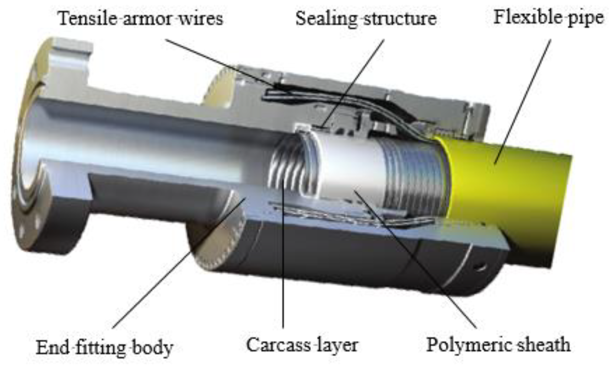
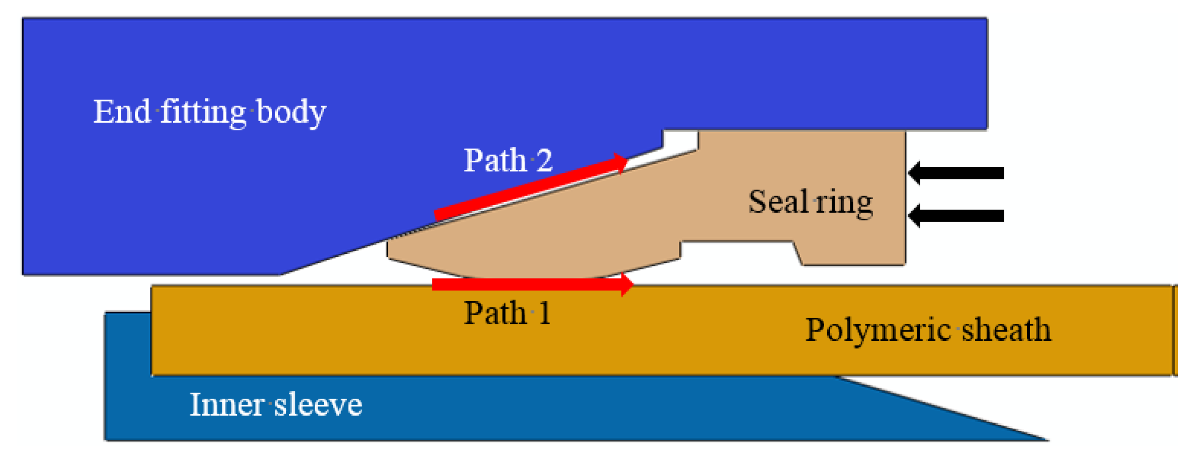
2.1. Sealing Structure
2.2. Sealing Criteria
2.3. Thermal Sealing Analysis
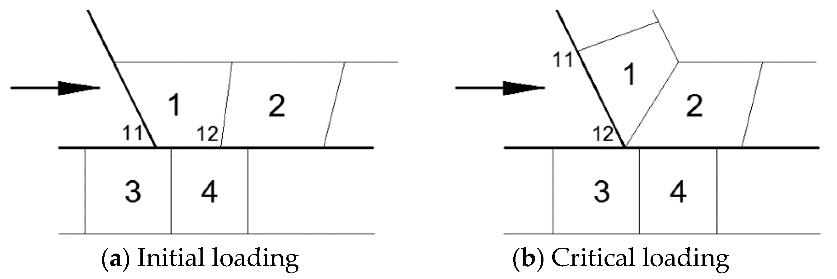
2.4. Mechanical Analysis
3. FE Modeling Procedures
4. Results and Discussion
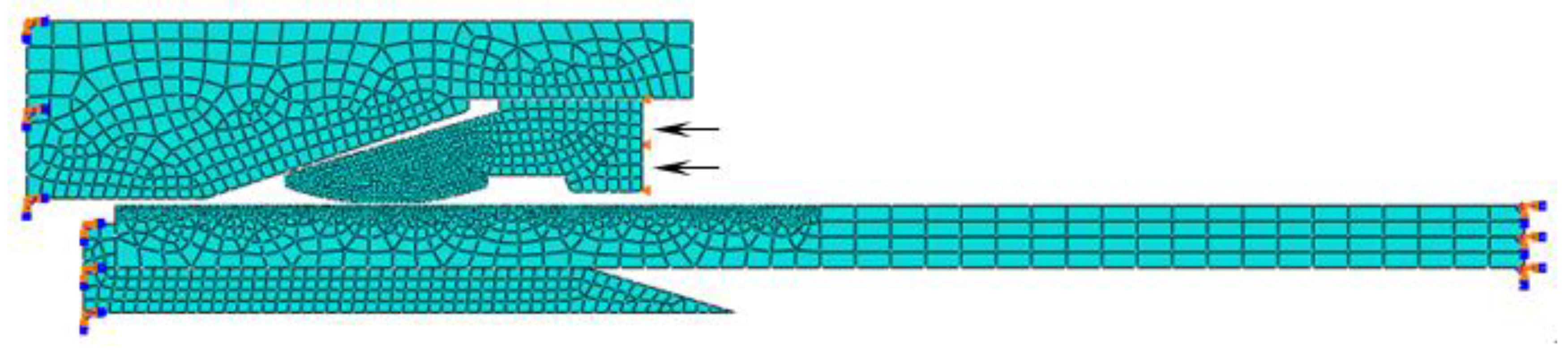
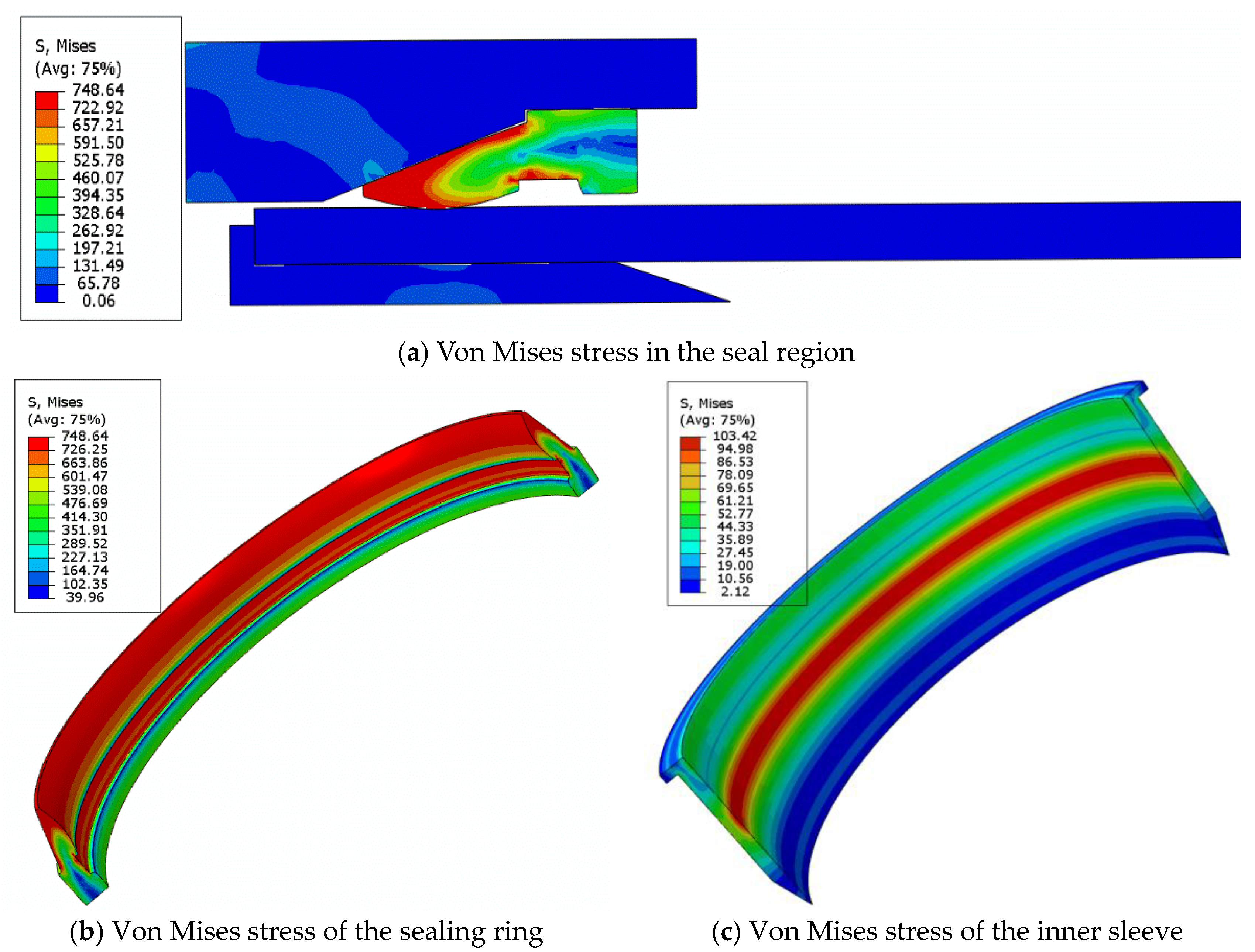
4.1. Simulation of Sealing Principle
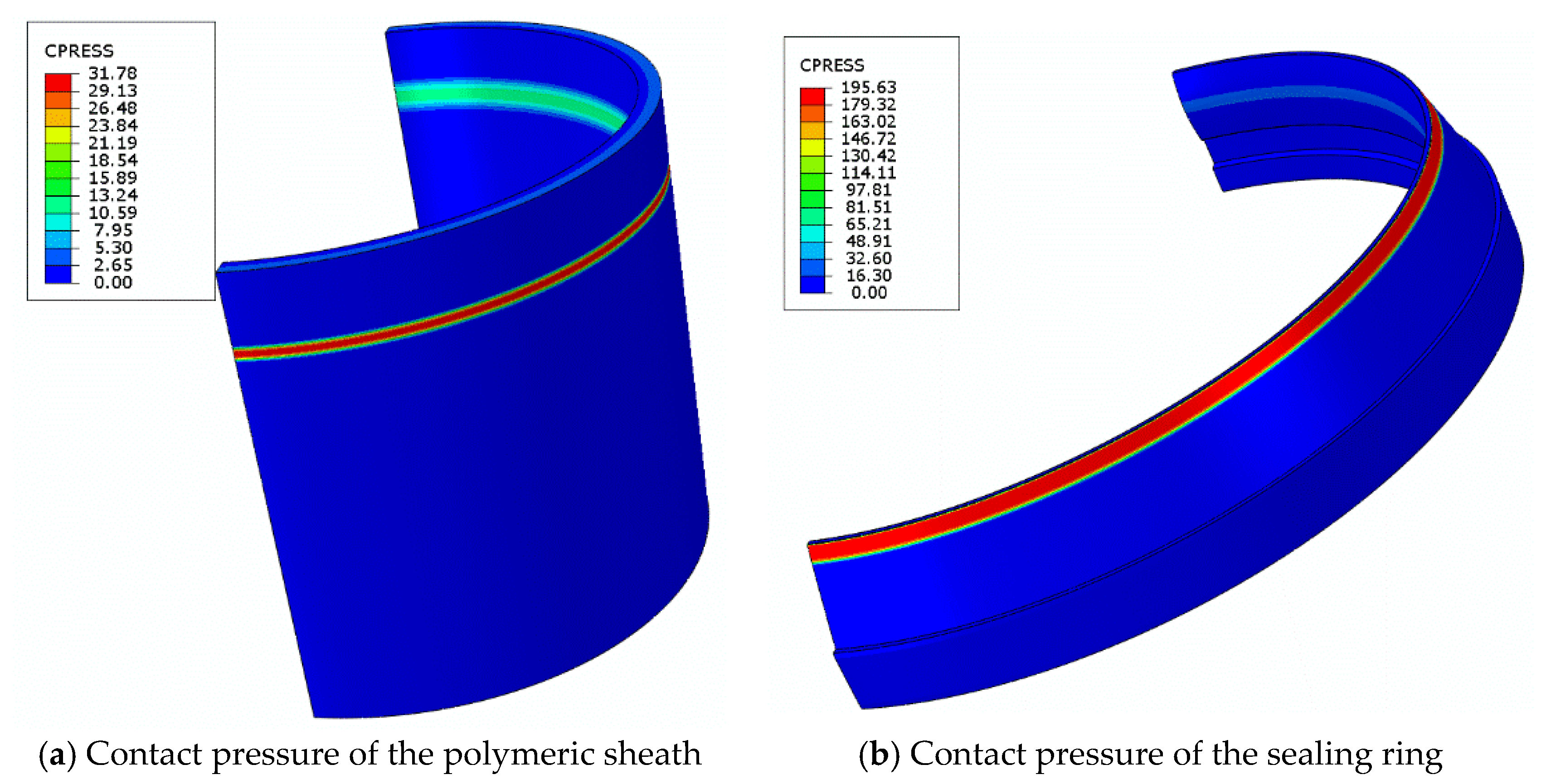
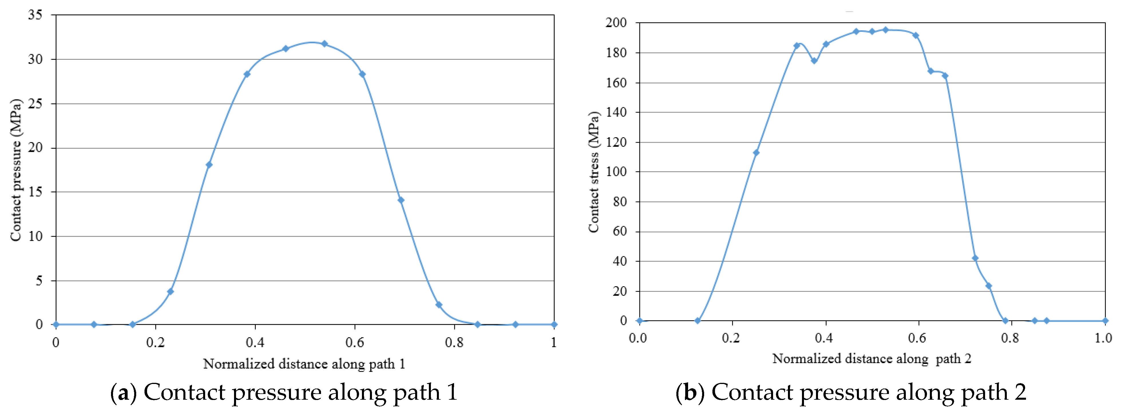
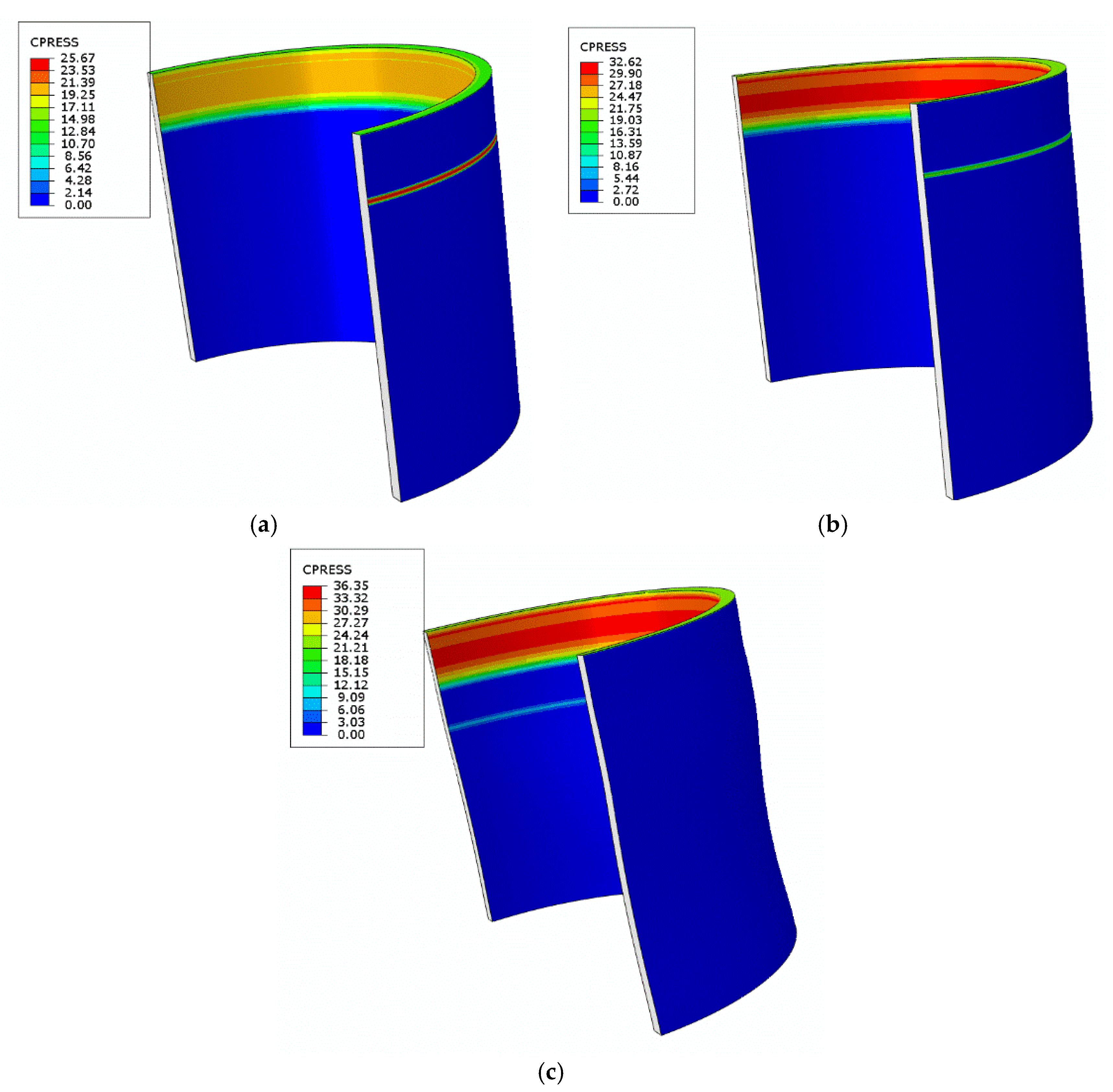
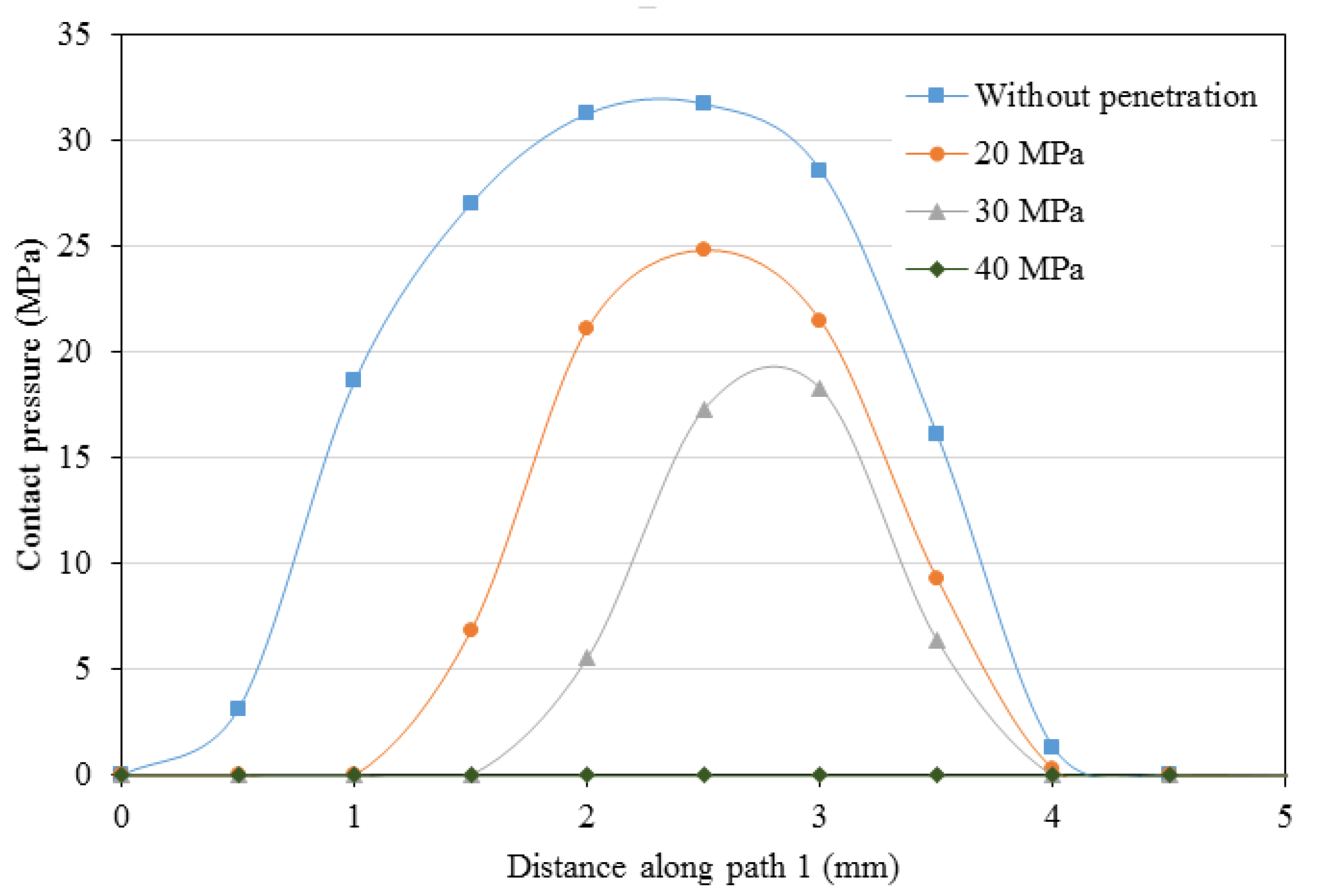
4.2. Analysis of Pressure Penetration
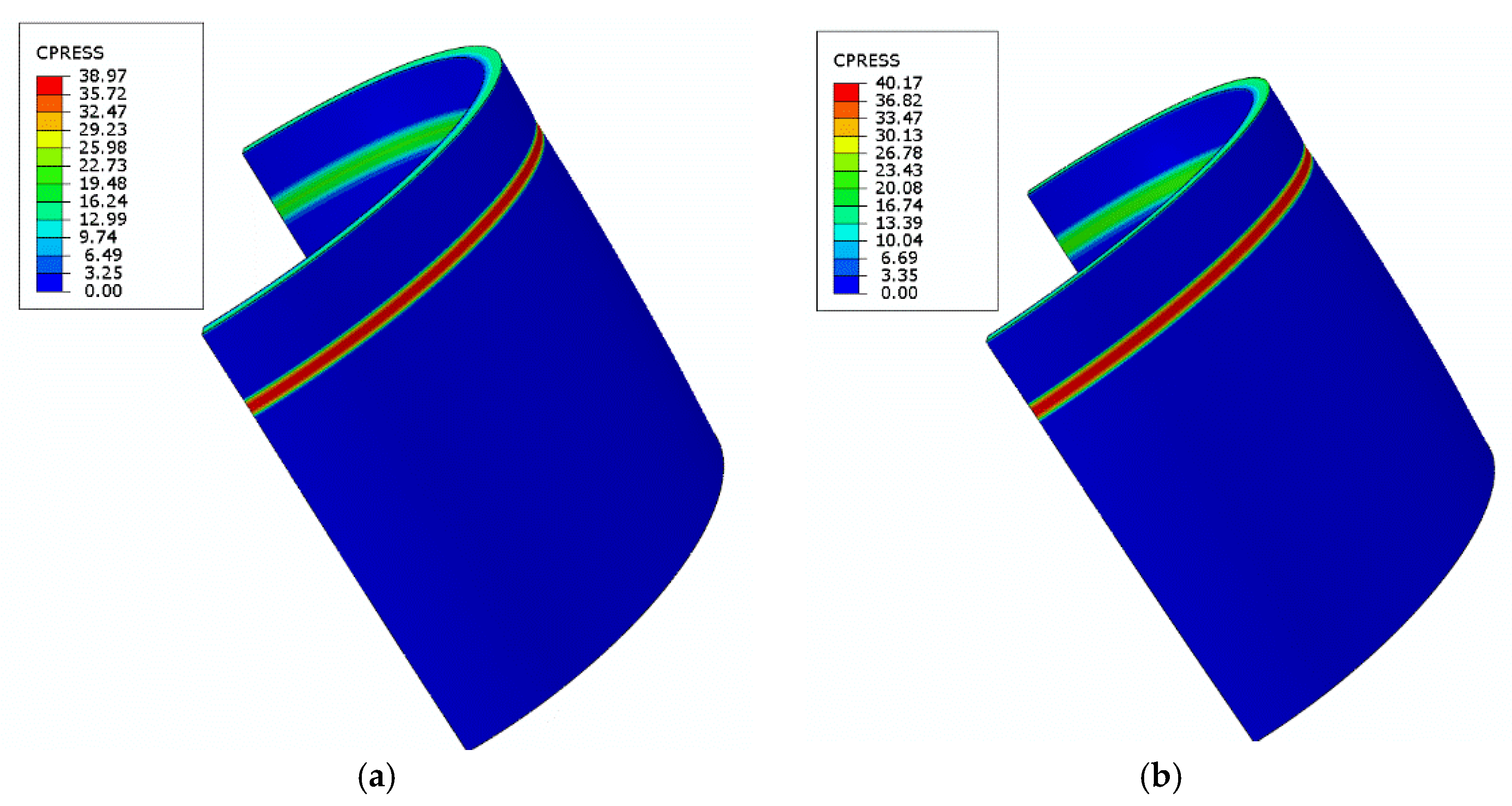
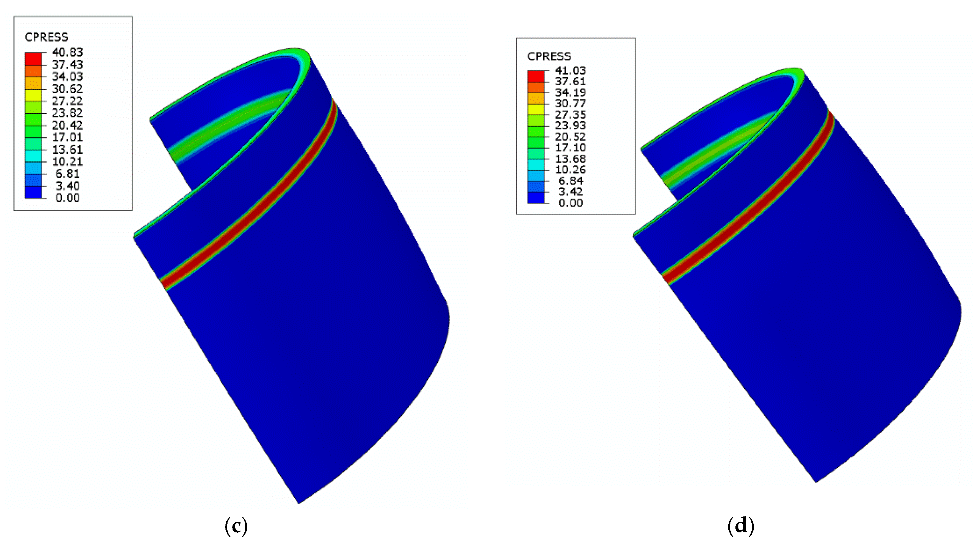
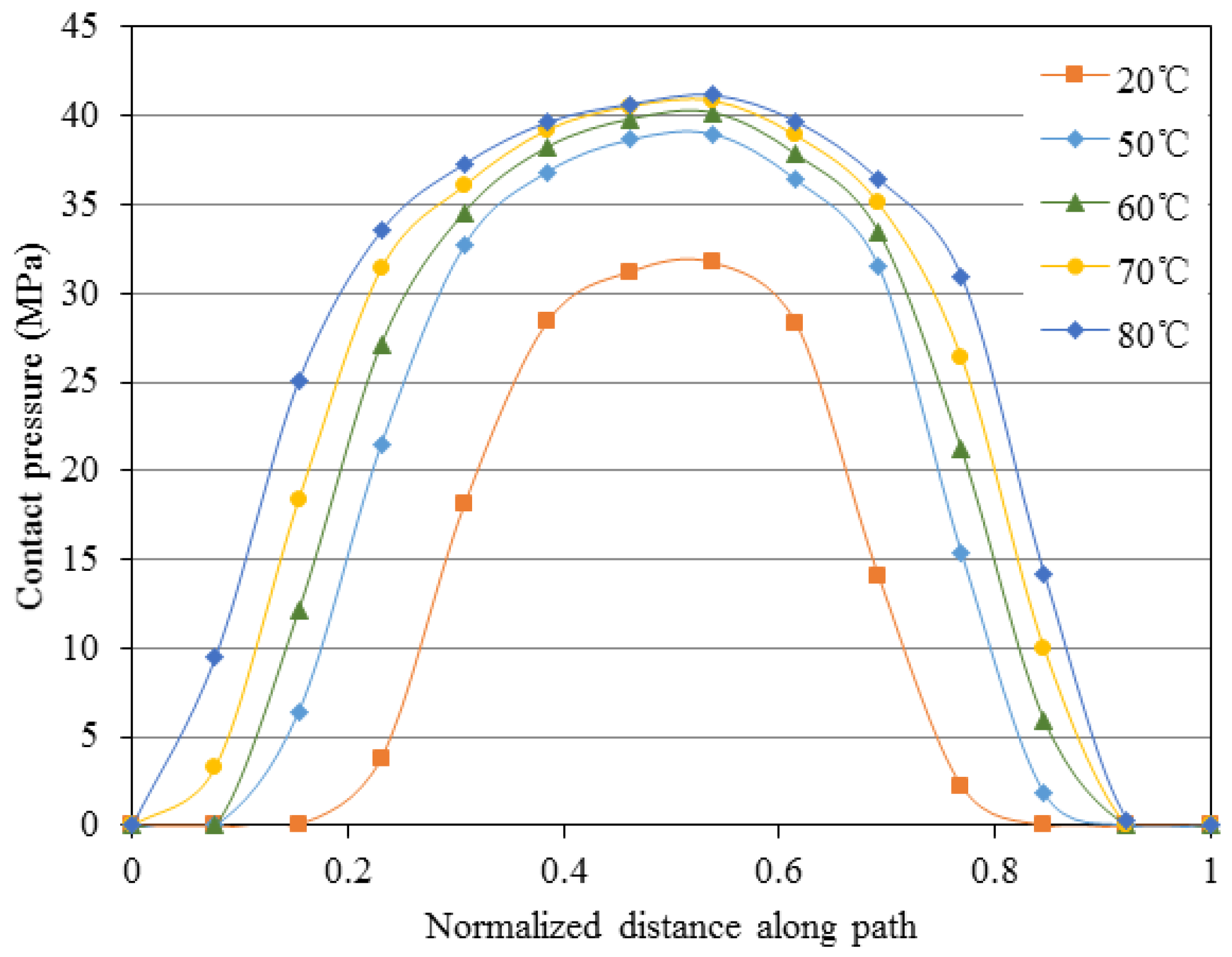
4.3. Analysis of the Thermal Sealing
5. Conclusions
Author Contributions
Funding
Conflicts of Interest
References
- Moan, T.; Amdahl, J.; Ersdal, G. Assessment of ship impact risk to offshore structures-New NORSOK N-003 guidelines. Mar. Struct. 2019, 63, 480–494. [Google Scholar] [CrossRef]
- Yang, C.K.; Kim, M.H. Numerical assessment of the global performance of spar and FPSO connected by horizontal pipeline bundle. Ocean Eng. 2018, 159, 150–164. [Google Scholar] [CrossRef]
- Zhang, J.M.; Li, X.S.; Chen, Z.Y.; Zhang, Y.; Li, G.; Yan, K.F.; Lv, T. Gas-Lifting characteristics of methane-water mixture and its potential application for self-eruption production of marine natural gas hydrates. Energies 2018, 11, 240. [Google Scholar] [CrossRef]
- Guha, I.; White, D.J.; Randolph, M.F. Subsea pipeline walking with velocity dependent seabed friction. Appl. Ocean Res. 2019, 82, 296–308. [Google Scholar] [CrossRef]
- Zhang, P.; Huang, Y.F.; Wu, Y. Springback coefficient research of API X60 pipe with dent defect. Energies 2018, 11, 3213. [Google Scholar] [CrossRef]
- Paiva, L.F.; Vaz, M.A. An empirical model for flexible pipe armor wire lateral buckling failure load. Appl. Ocean Res. 2017, 66, 46–54. [Google Scholar] [CrossRef]
- Anderson, T.A.; Vermiyea, M.E.; Dodds, V.J.N.; Finch, D.; Latto, J.R. Qualification of flexible fiber-reinforced pipe for 10,000-foot water depths. In Proceedings of the Offshore Technology Conference, Houston, TX, USA, 6–9 May 2013. [Google Scholar]
- Pham, D.C.; Sridhar, N.; Qian, X.; Sobey, A.J.; Achintha, M. A review on design, manufacture and mechanics of composite risers. Ocean Eng. 2016, 112, 82–96. [Google Scholar] [CrossRef] [Green Version]
- Dahl, C.S.; Andersen, B.; Groenne, M. Developments in managing flexible risers and pipelines, a suppliers perspective. In Proceedings of the Offshore Technology Conference, Houston, TA, USA, 2–5 May 2011. [Google Scholar]
- Ebrahimi, A.; Kenny, S.; Hussein, A. Radial buckling of tensile armor wires in subsea flexible pipe—Numerical assessment of key factors. ASME J. Offshore Mech. Arct. Eng. 2016, 138, 031701. [Google Scholar] [CrossRef]
- Drumond, G.P.; Geovana, P.; Pasqualino, I.P.; Pinheiro, B.C.; Estefen, S.F. Pipelines, risers and umbilicals failures: A literature review. Ocean Eng. 2017, 148, 412–425. [Google Scholar] [CrossRef]
- API 17B. Recommended Practice for Flexible Pipe, 5th ed.; American Petroleum Institute: Washington, DC, USA, 2014. [Google Scholar]
- Campello, G.C.; Sousa, J.R.M.; Vardaro, E. An analytical approach to predict the fatigue life of flexible pipes inside end fittings. In Proceedings of the Offshore Technology Conference, Houston, TX, USA, 2–5 May 2016. [Google Scholar]
- Fernando, U.S.; Nott, P.; Graham, G.; Roberts, A.E.; Sheldrake, T. Experimental evaluation of the metal-to-metal seal design for high-pressure flexible pipes. In Proceedings of the Offshore Technology Conference, Houston, TX, USA, 30 April–3 May 2012. [Google Scholar]
- Hatton, S.; Rumsey, L.; Biragoni, P.; Roberts, D. Development and qualification of end fittings for composite riser pipe. In Proceedings of the Offshore Technology Conference, Houston, TX, USA, 6–9 May 2013. [Google Scholar]
- Peng, G.; Zhang, Z.; Li, W. Computer vision algorithm for measurement and inspection of O-rings. Measurement 2016, 94, 828–836. [Google Scholar] [CrossRef]
- Liu, X.; Li, G.; Yue, Q.; Oberlies, R. Acceleration-oriented design optimization of ice-resistant jacket platforms in the Bohai Gulf. Ocean Eng. 2009, 36, 1295–1302. [Google Scholar] [CrossRef]
- Tang, M.; Lu, Q.; Yan, J.; Yue, Q. Buckling collapse study for the carcass layer of flexible pipes using a strain energy equivalence method. Ocean Eng. 2016, 111, 209–217. [Google Scholar] [CrossRef]
- Cour, D.; Kristensen, C.; Nielsen, N.J.R. Managing fatigue in deepwater flexible risers. In Proceedings of the Offshore Technology Conference, Houston, TX, USA, 5–8 May 2008. [Google Scholar]
- Li, X.; Jiang, X.; Hopman, H. A review on predicting critical collapse pressure of flexible risers for ultra-deep oil and gas production. Appl. Ocean Res. 2018, 80, 1–10. [Google Scholar] [CrossRef]
- Wang, L.Q.; Wei, Z.L.; Yao, S.M.; Guan, Y.; Li, S.K. Sealing performance and optimization of a subsea pipeline mechanical connector. Chin. J. Mech. Eng. 2018, 31, 1–14. [Google Scholar] [CrossRef]
- Fernando, U.S.; Karabelas, G. Analysis of end fitting barrier seal performance in high pressure un-bonded flexible pipes. In Proceedings of the 33rd ASME International Conference on Ocean, Offshore and Arctic Engineering, San Francisco, CA, USA, 8–13 June 2014. [Google Scholar]
- Li, X.; Du, X.; Wan, J.; Xiao, H. Structure analysis of flexible pipe end fitting seal system. In Proceedings of the 34th ASME International Conference on Ocean, Offshore and Arctic Engineering, St John’s, NL, Canada, 31 May–5 June 2015. [Google Scholar]
- Zhang, L.; Yang, Z.; Lu, Q.; Yan, J.; Chen, J.; Yue, Q. Numerical simulation on the sealing performance of serrated teeth inside the wedgy sealing ring of end fitting of marine flexible pipeline. Oil Gas Storage Transp. 2017, 37, 108–115. (In Chinese) [Google Scholar]
- Marion, A.; Rigaud, J.; Werth, M.; Martin, J. γ-Flex®: A new material for high temperature flexible pipes. In Proceedings of the Offshore Technology Conference, Houston, TX, USA, 6–9 May 2002. [Google Scholar]
- API 17J. Specification for Un-Bonded Flexible Pipe, 4th ed.; American Petroleum Institute: Washington, DC, USA, 2014. [Google Scholar]
- Yan, H.; Zhao, Y.; Liu, J.; Jiang, H. Analyses toward factors influencing sealing clearance of a metal rubber seal and derivation of a calculation formula. Chin. J. Aeronaut. 2016, 29, 292–296. [Google Scholar] [CrossRef] [Green Version]
- Gorash, Y.; Dempster, W.; Nicholls, W.D.; Hamilton, R. Fluid pressure penetration for advanced FEA of metal-to-metal seals. Proc. Appl. Math. Mech. 2015, 15, 197–198. [Google Scholar] [CrossRef] [Green Version]
- Zhao, B.; Zhao, Y.; Wu, X.; Xiong, H. Sealing performance analysis of P-shape seal with fluid pressure penetration loading method. IOP Conf. Ser. Mater. Sci. Eng. 2018, 397, 012126. [Google Scholar] [CrossRef]
- Slee, A.J.; Stobbart, J.; Gethin, D.T.; Hardy, S.J. Case study on a complex seal design for a high pressure vessel application. In Proceedings of the ASME Pressure Vessels and Piping Conference, Anaheim, CA, USA, 20–24 July 2014. [Google Scholar]
- Wang, B.; Peng, X.; Meng, X. A thermo-elastohydrodynamic lubrication model for hydraulic rod O-ring seals under mixed lubrication conditions. Tribol. Int. 2019, 129, 442–458. [Google Scholar] [CrossRef]
- Deng, D.; Zhang, C.; Pu, X.; Liang, W. Influence of material model on prediction accuracy of welding residual stress in an austenitic stainless steel multi-pass buttwelded joint. J. Mater. Eng. Perform. 2017, 26, 1494–1505. [Google Scholar] [CrossRef]
- Yu, C.; Heinrich, J. Petrov-Galerkin methods for the time-dependent convective transport equation. Int. J. Numer. Meth. Eng. 1986, 23, 883–902. [Google Scholar] [CrossRef]
- Yu, C.; Heinrich, J. Petrov-Galerkin method for multidimensional, time-dependent, Convective-Diffusive equations. Int. J. Numer. Meth. Eng. 1987, 24, 2201–2215. [Google Scholar] [CrossRef]
- Yu, R.; Yuan, P. Structure and research focus of marine un-bonded flexible pipes. Oil Gas Storage Transp. 2016, 35, 1255–1260. (In Chinese) [Google Scholar]
- Malta, E.; Martins, C. Finite element analysis of flexible pipes under axial compression: Influence of the sample length. ASME J. Offshore Mech. Arct. Eng. 2017, 139, 011701. [Google Scholar] [CrossRef]
- Cuamatzi-Melendez, R.; Castillo-Hernandez, O.; Vazquez-Hernandez, A.O.; Vaz, M.A. Finite element and theoretical analyses of bisymmetric collapses in flexible risers for deepwaters developments. Ocean Eng. 2017, 140, 195–208. [Google Scholar] [CrossRef]
- Pethrick, R.A.; Banks, W.M.; Brodesser, M. Ageing of thermoplastic umbilical hose materials used in a marine environment 1-Polyethylene. Proc. Inst. Mech. Eng. Part L J. Mater. Des. Appl. 2014, 228, 45–62. [Google Scholar] [CrossRef]


| Component | Young’s Modulus (GPa) | Poisson’s Ratio | Yield Strength (MPa) |
|---|---|---|---|
| End fitting body | 210 | 0.3 | 355 |
| inner sleeve | 210 | 0.3 | 355 |
| Sealing ring | 191 | 0.3 | 758 |
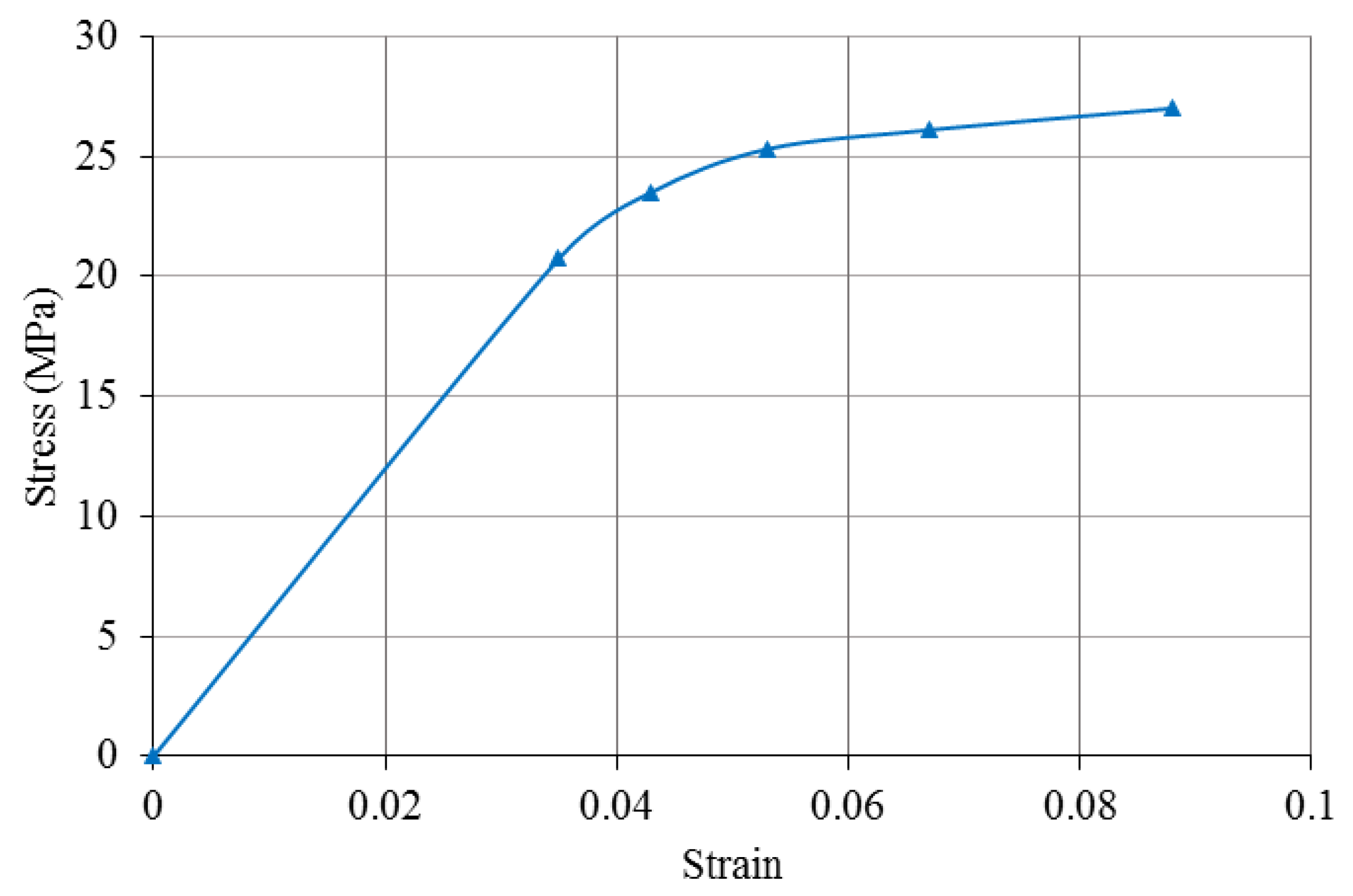
| Polymeric sheath | 0.571 | 0.45 | 20.74 |
| Temperature (°C) | 20 | 50 | 60 | 70 | 80 |
| Von Mises stress (MPa) | 748.6 | 750.1 | 751.6 | 753.7 | 756.8 |
| Contact pressure in path 1 (MPa) | 31.7 | 38.9 | 40.1 | 40.8 | 41.3 |
| Contact pressure in path 2 (MPa) | 195.6 | 199.7 | 227.3 | 229.4 | 234.5 |
© 2019 by the authors. Licensee MDPI, Basel, Switzerland. This article is an open access article distributed under the terms and conditions of the Creative Commons Attribution (CC BY) license (http://creativecommons.org/licenses/by/4.0/).
Share and Cite
Tang, L.; He, W.; Zhu, X.; Zhou, Y. Sealing Performance Analysis of an End Fitting for Marine Unbonded Flexible Pipes Based on Hydraulic-Thermal Finite Element Modeling. Energies 2019, 12, 2198. https://0-doi-org.brum.beds.ac.uk/10.3390/en12112198
Tang L, He W, Zhu X, Zhou Y. Sealing Performance Analysis of an End Fitting for Marine Unbonded Flexible Pipes Based on Hydraulic-Thermal Finite Element Modeling. Energies. 2019; 12(11):2198. https://0-doi-org.brum.beds.ac.uk/10.3390/en12112198
Chicago/Turabian StyleTang, Liping, Wei He, Xiaohua Zhu, and Yunlai Zhou. 2019. "Sealing Performance Analysis of an End Fitting for Marine Unbonded Flexible Pipes Based on Hydraulic-Thermal Finite Element Modeling" Energies 12, no. 11: 2198. https://0-doi-org.brum.beds.ac.uk/10.3390/en12112198