Exploiting Elastically Supported Masses in Cantilever for Resonance Frequencies Down-Shifted Vibration Energy Harvester


Abstract
:
1. Introduction
2. Theory and Design
3. Results and Discussion
4. Conclusions
Author Contributions
Funding
Conflicts of Interest
References
- Alameh, A.H.; Gratuze, M.; Elsayed, M.Y.; Nabki, F. Effects of proof mass geometry on piezoelectric vibration energy harvesters. Sensors 2018, 18, 1584. [Google Scholar] [CrossRef] [PubMed]
- Kubba, A.E.; Jiang, K. Efficiency enhancement of a cantilever-based vibration energy harvester. Sensors 2013, 14, 188–211. [Google Scholar] [CrossRef] [PubMed]
- Savarimuthu, K.; Sankararajan, R.; Roji M., A.M. Design and analysis of cantilever based piezoelectric vibration energy harvester. Circuit World 2018, 44, 78–86. [Google Scholar] [CrossRef]
- Yang, Z.; Zhou, S.; Zu, J.; Inman, D. High-performance piezoelectric energy harvesters and their applications. Joule 2018, 2, 642–697. [Google Scholar] [CrossRef]
- Dhote, S.; Li, H.; Yang, Z. Multi-frequency responses of compliant orthoplanar spring designs for widening the bandwidth of piezoelectric energy harvesters. Int. J. Mech. Sci. 2019, 157–158, 684–691. [Google Scholar] [CrossRef]
- Nabavi, S.; Zhang, L. Nonlinear multi-mode wideband piezoelectric mems vibration energy harvester. IEEE Sens. J. 2019. [Google Scholar] [CrossRef]
- Zhou, Z.; Qin, W.; Du, W.; Zhu, P.; Liu, Q. Improving energy harvesting from random excitation by nonlinear flexible bi-stable energy harvester with a variable potential energy function. Mech. Syst. Signal Process. 2019, 115, 162–172. [Google Scholar] [CrossRef]
- Kathpalia, B.; Tan, D.; Stern, I.; Erturk, A. An experimentally validated model for geometrically nonlinear plucking-based frequency up-conversion in energy harvesting. Smart Mater. Struct. 2018, 27, 015024. [Google Scholar] [CrossRef]
- Fan, K.; Chang, J.; Chao, F.; Pedrycz, W. Design and development of a multipurpose piezoelectric energy harvester. Energy Convers. Manag. 2015, 96, 430–439. [Google Scholar] [CrossRef]
- Luo, C.; Xia, M.; Wang, Y.; Li, P.; Hu, J.; Li, G.; Jiang, H.; Zhang, W. A multiple vibration modes separation technique based on 3*5 element energy harvester array: Frequency, bandwidth adjustment, and electrical characterization. IEEE Sens. J. 2017, 17, 6378–6384. [Google Scholar] [CrossRef]
- Wang, H.; Hu, F.; Wang, K.; Liu, Y.; Zhao, W. Three-dimensional piezoelectric energy harvester with spring and magnetic coupling. Appl. Phys. Lett. 2017, 110, 163905. [Google Scholar] [CrossRef]
- Cao, S.; Liu, L.; Zheng, J.; Pan, R.; Song, G. Modeling and analysis of galfenol nonlinear cantilever energy harvester with elastic magnifier. IEEE Trans. Magn. 2019, 55. [Google Scholar] [CrossRef]
- Aldraihem, O.; Baz, A. Energy harvester with a dynamic magnifier. J. Intell. Mater. Syst. Struct. 2011, 22, 521–530. [Google Scholar] [CrossRef]
- Zhou, W.; Penamalli, G.R.; Zuo, L. An efficient vibration energy harvester with a multi-mode dynamic magnifier. Smart Mater. Struct. 2012, 21, 015014. [Google Scholar] [CrossRef]
- Seo, M.-H.; Choi, D.-H.; Kim, I.-H.; Jung, H.-J.; Yoon, J.-B. Multi-resonant energy harvester exploiting high-mode resonances frequency down-shifted by a flexible body beam. Appl. Phys. Lett. 2012, 101, 123903. [Google Scholar] [CrossRef]
- Kim, I.-H.; Jang, S.-J.; Jung, H.-J. Design and experimental study of an l shape piezoelectric energy harvester. Shock Vib. 2017, 2017. [Google Scholar] [CrossRef]
- Sun, S.; Tse, P.W. Modeling of a horizontal asymmetric u-shaped vibration-based piezoelectric energy harvester (u-vpeh). Mech. Syst. Signal Process. 2019, 114, 467–485. [Google Scholar] [CrossRef]
- Zhang, H.; Ahmadi, M. Resonance tuning of a multi-piezoelectric bimorph beams energy harvester connected by springs. Ferroelectrics 2014, 460, 34–48. [Google Scholar] [CrossRef]
- Zhang, H.; Afzalul, K. Design and analysis of a connected broadband multi-piezoelectric-bimorph-beam energy harvester. IEEE Trans. Ultrason. Ferroelectr. Freq. Control 2014, 61, 1016–1023. [Google Scholar] [CrossRef]
- DuToit, N.E.; Wardle, B.L. Experimental verification of models for microfabricated piezoelectric vibration energy harvesters. AIAA J. 2007, 45, 1126–1137. [Google Scholar] [CrossRef]
- Sodano, H.A.; Park, G.; Inman, D.J. Estimation of electric charge output for piezoelectric energy harvesting. Strain 2004, 40, 49–58. [Google Scholar] [CrossRef]
- Toyabur, R.M.; Salauddin, M.; Park, J.Y. Design and experiment of piezoelectric multimodal energy harvester for low frequency vibration. Ceram. Int. 2017, 43, S675–S681. [Google Scholar] [CrossRef]
- Tang, L.; Yang, Y.; Wu, H. Modeling and experiment of a multiple-dof piezoelectric energy harvester. Proc. SPIE 2012, 8341, 83411E. [Google Scholar]
- Yildirim, T.; Ghayesh, M.H.; Li, W.; Alici, G. A review on performance enhancement techniques for ambient vibration energy harvesters. Renew. Sustain. Energy Rev. 2017, 71, 435–449. [Google Scholar] [CrossRef] [Green Version]


| Name | Length (mm) | Width (mm) | Thickness (mm) |
|---|---|---|---|
| PZT | 20 | 19.5 | 0.2 |
| Cantilever beam | 80 | 40 | 0.5 |
| Bracket | 40 | 100 | 0.8 |
| k (N/m) | 6 | 10 | 14 | 18 | 22 |
| dimensionless voltage | 1.8 | 1.9 | 2.2 | 2.6 | 3.3 |
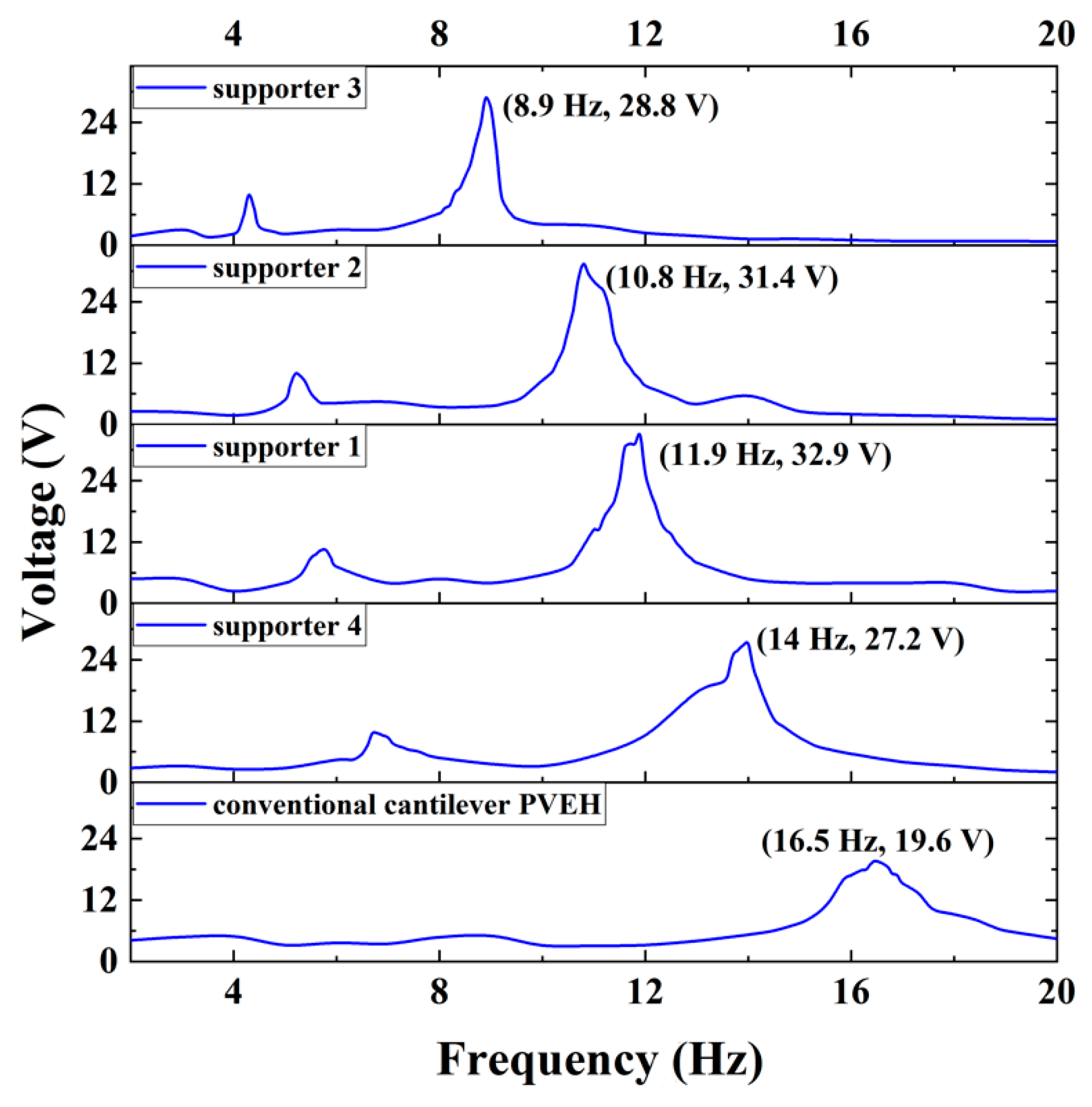
| Type | Material of Support | Length |
|---|---|---|
| supporter 1 | rubber band | 90 mm |
| supporter 2 | rubber band | 130 mm |
| supporter 3 | rubber band | 170 mm |
| supporter 4 | Al alloy of 6050 | 100 mm |
© 2019 by the authors. Licensee MDPI, Basel, Switzerland. This article is an open access article distributed under the terms and conditions of the Creative Commons Attribution (CC BY) license (http://creativecommons.org/licenses/by/4.0/).
Share and Cite
Wang, H.; Li, B.; Liu, Y.; Zhang, M.; Zhao, W.; Qin, H. Exploiting Elastically Supported Masses in Cantilever for Resonance Frequencies Down-Shifted Vibration Energy Harvester. Energies 2019, 12, 2207. https://0-doi-org.brum.beds.ac.uk/10.3390/en12112207
Wang H, Li B, Liu Y, Zhang M, Zhao W, Qin H. Exploiting Elastically Supported Masses in Cantilever for Resonance Frequencies Down-Shifted Vibration Energy Harvester. Energies. 2019; 12(11):2207. https://0-doi-org.brum.beds.ac.uk/10.3390/en12112207
Chicago/Turabian StyleWang, Hai, Bin Li, Yan Liu, Min Zhang, Wei Zhao, and Hongbo Qin. 2019. "Exploiting Elastically Supported Masses in Cantilever for Resonance Frequencies Down-Shifted Vibration Energy Harvester" Energies 12, no. 11: 2207. https://0-doi-org.brum.beds.ac.uk/10.3390/en12112207