LCpL Filter Design and Control for Stability Improvement in a Stand-Alone Microgrid with Sub Inverter Structure


1
Department of Electrical and Biomedical Engineering, Hanyang University, Seoul 04763, Korea
2
Power and Industrial Systems R&D Center, Hyosung Corporation, Anyang 14080, Korea
*
Author to whom correspondence should be addressed.
Energies 2019, 12(12), 2318; https://0-doi-org.brum.beds.ac.uk/10.3390/en12122318
Submission received: 27 May 2019
/
Revised: 11 June 2019
/
Accepted: 12 June 2019
/
Published: 17 June 2019
Abstract
:The inverter of an energy storage system, which plays an important role in maintaining the voltage of a stand-alone microgrid, can shut down in response to external or internal abnormal conditions. Such a protective measure can cause the microgrid to blackout. A redundant inverter can be configured to respond upon failure of the main inverter to ensure higher stability of the stand-alone microgrid. However, the microgrid may experience several to tens of blackout cycles when the main inverter fails owing to a time delay in the operation of the sub inverter. To overcome this limitation, we propose an LCpL filter for suppressing any sudden changes in the microgrid during the transition period between the main and sub inverters. In addition, this study also describes a control method for the sub inverter to prevent system blackouts. A 100 kW microgrid system consisting of two 100 kW inverters with LCpL filters and loads was used to demonstrate the efficacy/utility of the proposed method.
1. Introduction
Renewable energy contributed to 10% of the world’s primary energy consumption in 2017 owing to improved technology and economic efficiency. In addition to the Paris Agreement, individual countries will continue to implement their own renewable energy support policies and their share is expected to increase to 17% by 2040 [1,2]. There has been an increase in wind and photovoltaic (PV) power generation in areas with grid parity due to continuous price reductions, and integrated operation with the energy storage system (ESS) has improved the sustainability of power generation. The development of such renewable energy technologies has been possible owing to a shift from the existing central power generation method to a distributed method using various new and renewable energy sources. Furthermore, this has enabled application expansion to microgrids and opportunities to conduct various research projects in this area [3,4,5,6].
Island areas have long been powered by diesel-powered plants as it is difficult to connect these areas to existing grids owing to technological or economic reasons. Diesel-powered generation has limitations, such as high fuel costs, the transfer, storage, and management of fuel, and CO2 emissions. Island microgrids, which use renewable energy sources and energy storage devices, have been introduced as a solution to overcome the above limitations [7,8,9]. A microgrid consisting of a 664.4 kW photovoltaic power generator, 837 kWh ESS, and diesel generator that has been built on the Robben Island in South Africa is expected to save 235,000 L of fossil fuel and reduce 820 tons of CO2 emissions per year [10,11]. An island microgrid consisting of two 250 kW wind power generators, a 114 kW photovoltaic power generator, 3.86 MWh ESS, and three 150 kW diesel generators has been constructed on Gapa Island in South Korea.
An island microgrid mainly consists of diesel generators, renewable energy sources, and the ESS. The power supply demands can be met without a diesel generator by using only a renewable energy generator and the ESS, if the combined energy from the renewable sources and ESS is greater than the total load. Under such conditions, the voltage of the island microgrid is controlled by the inverter of the ESS [12]. The inverter offers advantages such as quick response characteristics and a bidirectional power flow but is generally characterized by a relatively lower overload rate as compared to a diesel generator. Thus, inverters can be used in parallel in the microgrid to ensure higher grid voltage stability. Some of the inverters connected in parallel can be operated at all times, while others can be operated alternatively only in the event of a malfunction or during periods of inverter maintenance. Grid voltage recovery might be delayed when all inverters are operating in parallel and are shut down by a blackout resulting from a temporary overcurrent or similar problem. Thus, the stability of the island microgrid can be improved by using a sub inverter in the standby mode to ensure uninterruptible or fast grid voltage recovery in the event that the main inverter unexpectedly shuts down.
As mentioned above, a seamless transfer between the main and sub inverters in the microgrid is essential to ensure stable operation. Conventional studies have suggested mode transition algorithms between the current and voltage controls to achieve seamless transfer from the grid connected to stand-alone operations [13,14,15,16,17,18,19,20,21,22]. The droop [23,24,25,26,27,28] and master–slave controls [28,29,30,31,32] have been researched in parallel inverter operation algorithms, wherein a majority of the algorithms impose the condition that all the inverters connected in parallel should be operated.
In this paper, we propose a method to maintain the grid without power outages using a sub inverter in the standby mode in the event that the power supply from the main inverter in the standalone mode is unexpectedly shut down. The voltage fluctuation of the island microgrid is instantaneously analyzed when the main inverter switches off and a factor that activates the sub inverter to control the microgrid voltage without blackout is derived. This study proposes a new filter design, control, and operation technique for an inverter that can mitigate the abovementioned limitations. We test and verify the design, control, and operation of the proposed filter in an island microgrid test bed consisting of two 100 kW inverters.
2. System Description
Figure 1 shows the configuration of the island microgrid located on Gapa Island in South Korea. Power has been supplied in the past by three 150 kVA diesel generators, which have been supplemented with wind and photovoltaic power and an ESS to form a microgrid. Residential properties mainly contain 114 kW photovoltaic power generators, while two 250 kVA wind power generators function as the main power source. The installed wind turbine (WT) is essentially a squirrel-cage induction generator that can be directly connected to an AC grid, and offers economic advantages owing to the ease of control/operation and less demands on the system hardware requirements [33]. However, a large voltage fluctuation may occur owing to the overcurrent and transient currents at start-up when the turbine is directly connected to the grid without an inverter. Figure 1 shows that the wind turbine generator and the ESS are connected in a back-to-back configuration to eliminate/mitigate the effect of a large instantaneous fluctuation from the squirrel-cage induction generator, thus facilitating operation independent of the microgrid voltage.
The ESS can be operated in either a stand-alone or integrated mode with a diesel generator to control the power supply from the microgrid. The functioning of the diesel generator and ESS depends on the generated renewable energy (WT, PV), battery state of charge (SoC), and the loads as shown in Table 1. The diesel generator is stopped and power is supplied using the energy stored in the battery and from renewable sources when the battery SoC is: (1) greater than the set SoC that determines the operation of the ESS in the stand-alone mode; or (2) greater than the minimum SoC and the renewable energy generation is greater than the load. The island microgrid voltage at this point of time is controlled by the inverter connected to the ESS. A power failure may occur if the inverter stops operating owing to an overcurrent or malfunction from an external accident. A sub inverter is installed in parallel to the main inverter as a backup to prepare for a power blackout.
3. System Analysis
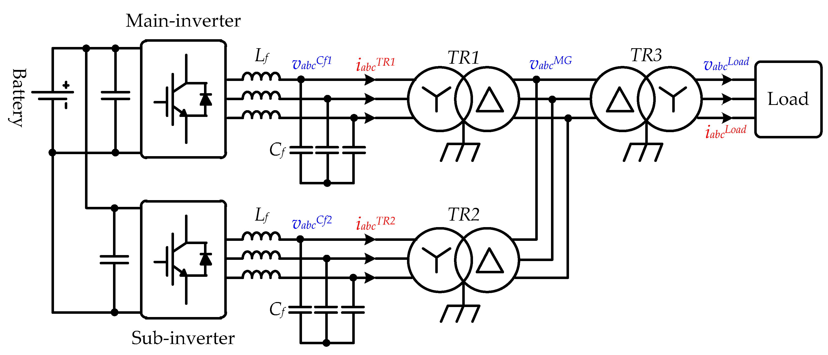
Figure 2 shows a simplified schematic of the island microgrid configuration from Figure 1 that is powered only by renewable energy sources (WT, PV) and the ESS. The wind power generator that is in a back-to-back configuration with the ESS does not directly affect the microgrid voltage and can thus be excluded from the configuration, as can the stand-alone operation of the ESS. The microgrid voltage can be controlled quickly by the sub inverter, which is in the standby mode, when the main inverter is powered off. For this operation, it is effective to transmit the stop signal of the main inverter to the sub inverter to maintain the grid voltage. Communication or hard wiring can be used for conveying information, wherein the signal transmission time delay, which depends on the transmission method, is known as tdelay.
Figure 2 shows that the microgrid can be simplified to only having the inverter filter capacitor and parallel circuit of the load resistance when the pulse width modulation (PWM) is interrupted owing to a malfunction in the main inverter containing an LC filter. Equation (1) shows that the voltage of an RC parallel circuit without power can be expressed as a negative exponential function. Here, C is the filter capacitor of the inverter and R is the load resistance.
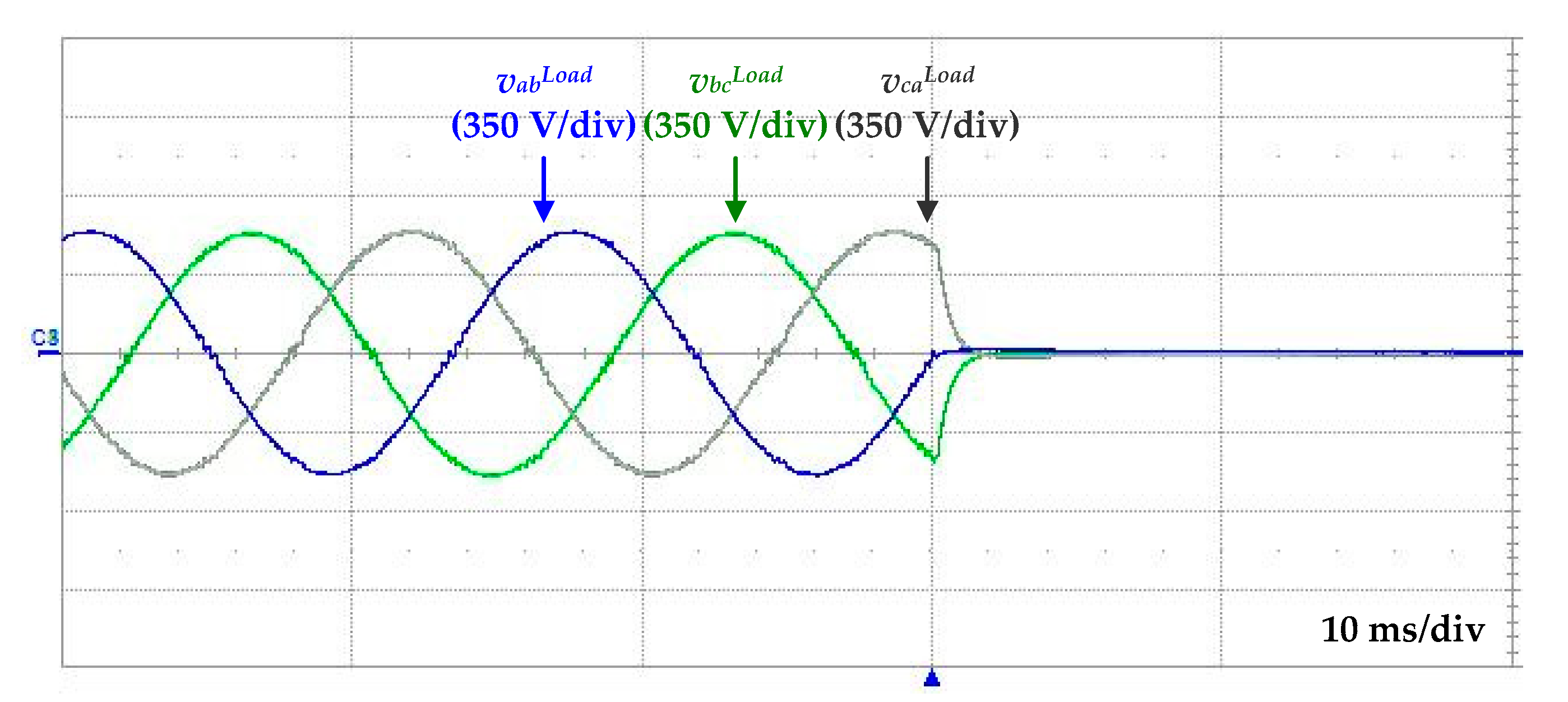
As shown in Equation (1), the grid voltage is a function of the RC filter circuit attenuation, with the detailed operation represented by the experimental waveform shown in Figure 3. The figure shows that when the main inverter stops where one of the three phase voltages equals zero (and remains at this value), the remaining two phases have the same magnitude, which is reduced by a negative exponential voltage of the opposite sign and converges to zero. Here, vab, vbc, and vca represent the line-to-line voltages of the load.
The activation of the sub inverter after the shutdown of the main inverter may lead to the occurrence of tdelay. A large difference between the actual grid and sub-inverter output voltages owing to the time delay can result in an offset in the transformer flux and generate an inrush current owing to the saturation phenomenon. The inrush current could be several times higher than the rated current of the inverter [34,35], and overcurrent protection may get activated when the sub-inverter is operated. Figure 4 shows the experimental waveforms of the inrush current as a function of the load voltage generated during inverter start-up, when fast system recovery control is used under a 10 kW load condition. Here, vab, vbc, and vca are the line-to-line voltages of the load and iaTR, ibTR, and icTR are the transformer currents. It can be confirmed that the inverter switches off when the transformer current exceeds the 200 A inverter current protection level.
Figure 5 shows that the cause of the above phenomenon corresponds to area F, which is the difference between the microgrid and original reference voltages during tdelay. During this period, the shutdown of the main inverter is recognized by the sub inverter after time tdelay and the voltage is controlled to equal the reference voltage. The magnetic flux offset corresponding to F is generated in the transformer and becomes saturated, which might produce an inrush current.
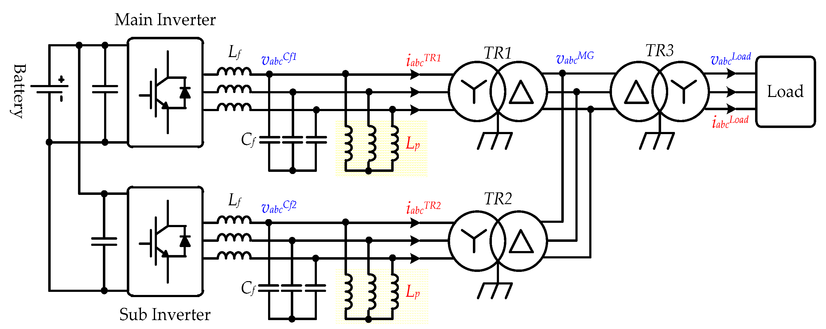
The difference between the original steady-state and microgrid voltages should be reduced during tdelay to quickly restore the microgrid voltage to its original value. The use of the LC parallel connected L filter, the LCpL filter, shown in Figure 6 is suggested to achieve the above. The inductor connected in parallel with the capacitor in the LCpL filter prevents the breakdown of the grid voltage when the inverter shuts down. It is also used to compensate for the reactive power flowing in the inverter capacitor when ESS is operated in an integrated mode with a diesel generator. The microgrid can be simplified to an RLC parallel circuit during the shutdown of the main inverter containing the LCpL filter. Equation (2) defines the RLC circuit voltage with underdamped characteristics, while Figure 7 shows the damped sinusoidal response characteristics.
Figure 7 shows that the area F is reduced during tdelay as compared to that in Figure 5, indicating that a decrease in the load power results in a decrease in area F. Thus, a decrease in voltage is suppressed during the time delay owing to the start-up/activation of the sub inverter.
4. Proposed LCpL Filter Design Method
In this paper, we propose a new LCpL filter design method for the fast recovery of grid voltage in the absence of the transformer inrush current during the shutdown and startup of the main and sub inverters, respectively. A load capacity that can be operated without inrush current in the transformer is determined taking into consideration the transformer saturation magnetic flux density based on the LCpL filter design. We consider a case wherein the load is balanced and can be approximated to the resistive load.
4.1. Design Procedure
LC filters are generally used in the inverter voltage source to reduce the switching frequency of the voltage. The resonance frequency of the LC filter is generally between 1/5th to 1/10th of the switching frequency, with an infinite combination of LC filters satisfying this condition. The LC filter combination is determined depending on the application. The filter inductor (Lf) can be determined by considering the ripple current limits and the magnitude of the voltage drop at the fundamental frequency. The filter capacitor (Cf) can be determined by considering factors such as the suppression of the voltage fluctuation due to load variation and capacitive reactive power limits [36,37,38].
The LCpL filter can be designed to resemble the LC filter and be its equivalent to reduce the switching frequency of the voltage. This is because the impedance of an inductor connected in parallel to the filter capacitor at the switching frequency is negligibly large. Additionally, the LCpL filter should be designed to have underdamped characteristics of the RLC parallel circuit in a certain load range during tdelay after stoppage of the main inverter. Furthermore, it is necessary to calculate the load range in which the magnetic flux of the transformer is not saturated when the sub inverter operates to restore the normal voltage. The reactive power of the LC parallel circuit should also be taken into consideration. The design procedure is outlined below:
- Equation (3) shows the characteristic equation for the RLC parallel circuit.The cut-off frequencies, LfCf and ωo, should be determined. In the above equation, ωo = 1/√(LpCf) and α = 1/2RCf. The condition α < ωo has to be satisfied to obtain an underdamped response, wherein the voltage equation can be expressed by Equation (2) and the natural resonance frequency ωd is given by √(ωo2 − α2) [39].
- The saturation flux density of the transformer Bs, nominal voltage vr, nominal frequency ωr, and flux density of the transformer at nominal voltage Br should be determined.
- The delay tdelay should be determined.
- The flux density surplus of the transformer Be is equal to Bs − Br.
- The natural frequency ωd is determined to be the nominal frequency.
- α is determined using Equation (4).Equation (4) defines the magnetic flux offset Bk caused by difference between the original reference and microgrid voltages during tdelay.where, NT is the number of turns in the transformer and A is its cross-sectional area.
- The power factor limit at the nominal frequency is determined when both the diesel generator and inverter are in operation. Using the set power factor, the reactive power Q is calculated from the fixed power factor PF as shown in Equation (5), where Pd represents the rated power of one phase of the diesel generator.
- The required total capacitance of the microgrid is calculated using ωd, Q, α, vr, and ωr. Equation (6) defines the reactive power CT || LT, which can be summarized using Equation (7). Here, CT and LT are the total capacitance and inductance of the microgrid, respectively.Equation (8) is valid under the underdamped response condition.Equation (9) given below can be derived from Equations (7) and (8).CT can be obtained using Equation (10) when ωd is equal to ωr, and results in Equation (11) when substituted with the equation for α.
- The value of Cf can be calculated by dividing CT by Ninv (the number of inverters).
- CT and α are used to calculate the value of R.
- ωo can be calculated using Equation (8), while LT is equal to 1/(ωo2CT) and Lp is LT × Ninv.
- Lf is equal to 1/(ωf2Cf).
4.2. Design Example
The ESS installed in the Gapa Island microgrid shown in Figure 1 has an inverter capacity of 1 MW. In this paper, we will design and test the filter of a 100 kW inverter. The design conditions/parameters are shown in Table 2.
The cut-off frequency of the LfCf filter was selected to be 560 Hz taking into consideration a switching frequency of 4.2 kHz to attenuate the harmonic voltage of inverter. The tdelay was 5 ms, and the magnetic flux surplus Be of the transformer was 0.67 tesla. The natural resonance frequency ωd was 377 Hz, Bk was about 0.666 tesla, and α was determined to be 193 from Equation (4).
The power factor limit was ≥0.99, reactive power Q was 2570 VA, and CT was determined to be 540 μF from Equation (11). The capacity of each inverter was 270 μF. The load resistance was 4.8 Ω based on the reference phase voltage, which allowed it to immediately follow the reference voltage without the transformer inrush current at a 30% inverter load factor. ωo was calculated from Equation (7), and LT and Lp were determined to be 10.3 mH and 20.6 mH, respectively, while Lf is 0.3 mH. The final values of the designed LfCfpLp have been listed in Table 3.
5. Proposed Control Method
5.1. Sub Inverter Startup Method
The magnitude of the microgrid voltage that decreases during tdelay after the main inverter has stopped was determined by the above designed LCpL filter and loads. The startup method of the sub inverter depends on the sensed voltage of the microgrid during tdelay.
Figure 8 shows a flowchart of the operation of the sub inverter. The sub inverter directly attains the reference voltage when the difference between the magnetic flux density variations corresponding to the reference and reduced microgrid voltages is lesser than the flux surplus in the transformer. In all other cases, the sub inverter starts in the soft start mode when the microgrid voltage falls below the minimum value. One could consider ways of changing the reference voltage to avoid the generation of the inrush current. However, this can cause a large voltage fluctuation and is hence not investigated in this paper.
5.2. Sub Inverter Control Algorithm
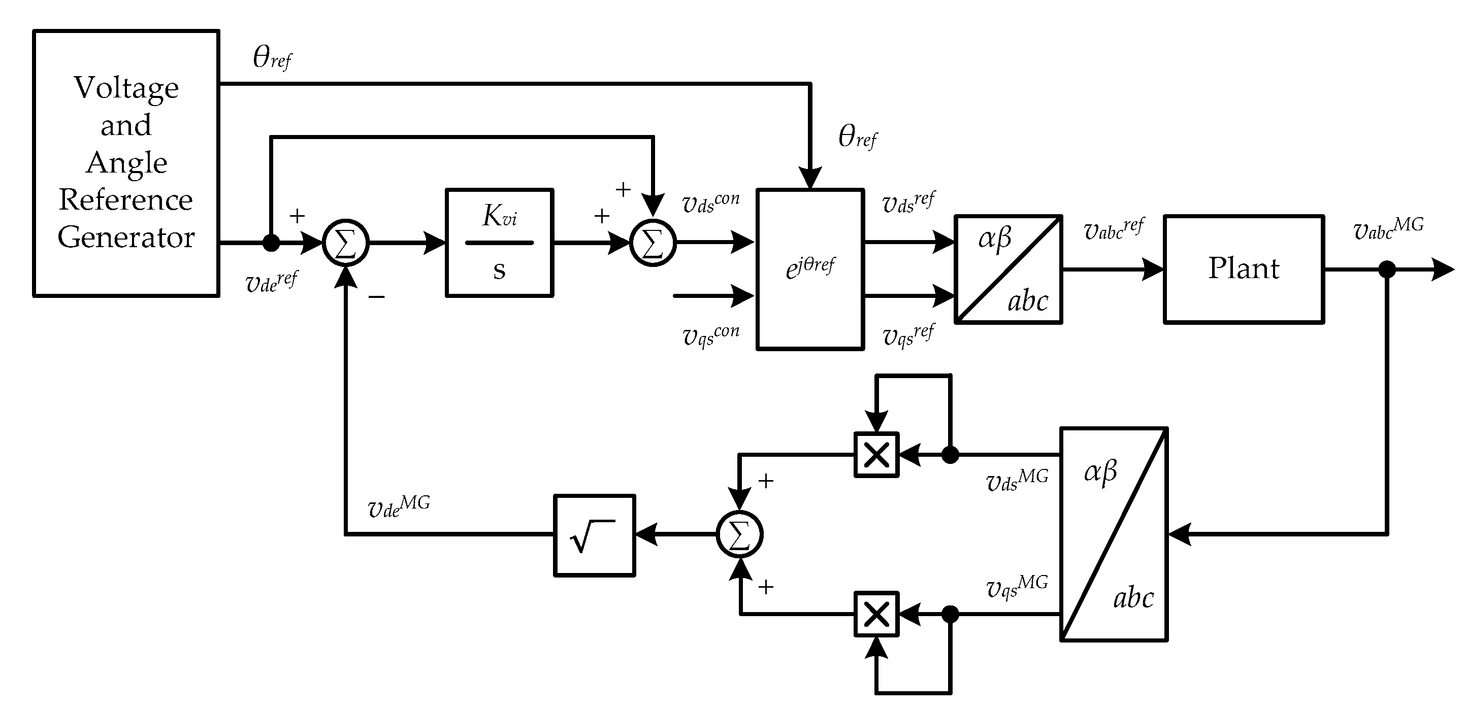
The sub inverter estimates the phase of the microgrid voltage in the standby mode. A fixed reference phase derived from a previous reference value obtained before tdelay was available when a stop signal was received from the main inverter. Figure 9 shows the block diagram of the sub inverter control algorithm. This study mainly focuses on the LCpL filter design and assesses the situation to immediately follow the reference voltage without inrush current in the transformer. Thus, we used a simple voltage control method in this study and did not address the voltage controller design problem. The voltage controller only controls the magnitude of the voltage using feedback, while the phase only calculates the initial value and generates the reference phase without any change.
6. Experimental Results
Figure 10 shows the diagram of the test configuration and the components used to verify the proposed LCpL filter design and control methods. The test components include a 480 kW DC power supply, two 100 kW 3-phase inverters, and a 100 kW load device. Hard wiring was used to transmit the stop signal of the main inverter and the relay (RB111A-24VAC/DC, ABB) circuits were configured. The tdelay occurred within 5 ms. Table 1 and Table 2 in Section 4.2 list the inverter parameters, and Table 3 shows the test conditions. The test conditions might vary depending on the load power and stop point. The PWM of the main inverter was stopped and the voltage control of the sub inverter was checked under each test condition. The test results were divided into two categories, namely seamless transfer, and soft-start. Seamless transfer refers to an immediate control required to reach the reference voltage value. Soft-start refers to the voltage recovery that takes place within tens of ms following a dip in the microgrid voltage below the reference value. Table 4 shows the experimental conditions that are dependent on the loads, stop phase of the main inverter, and voltage control methods.
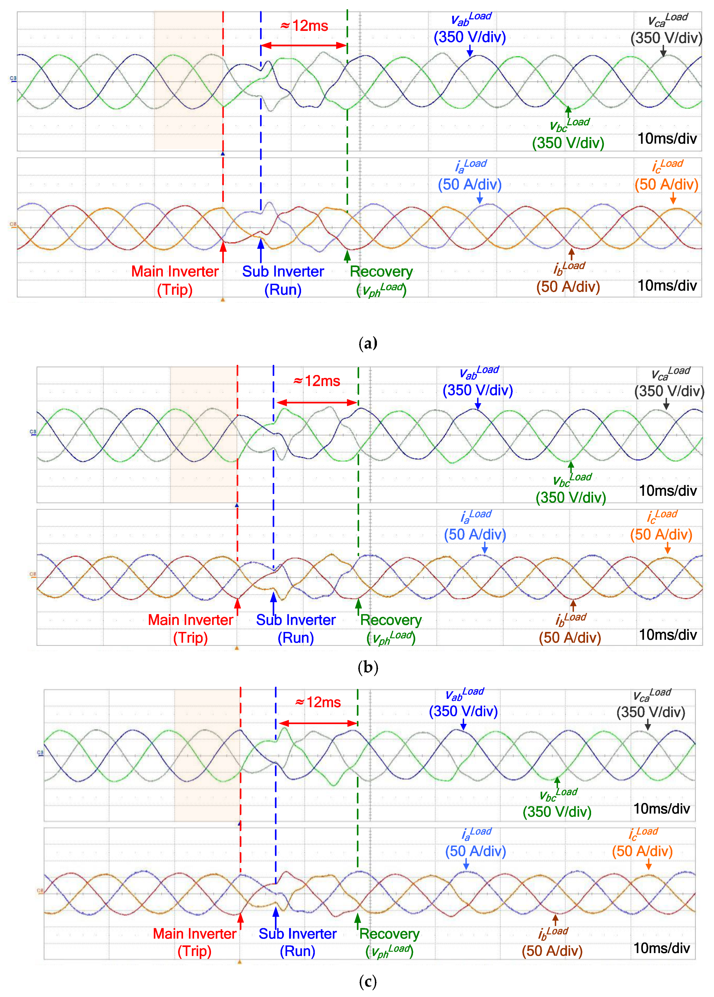
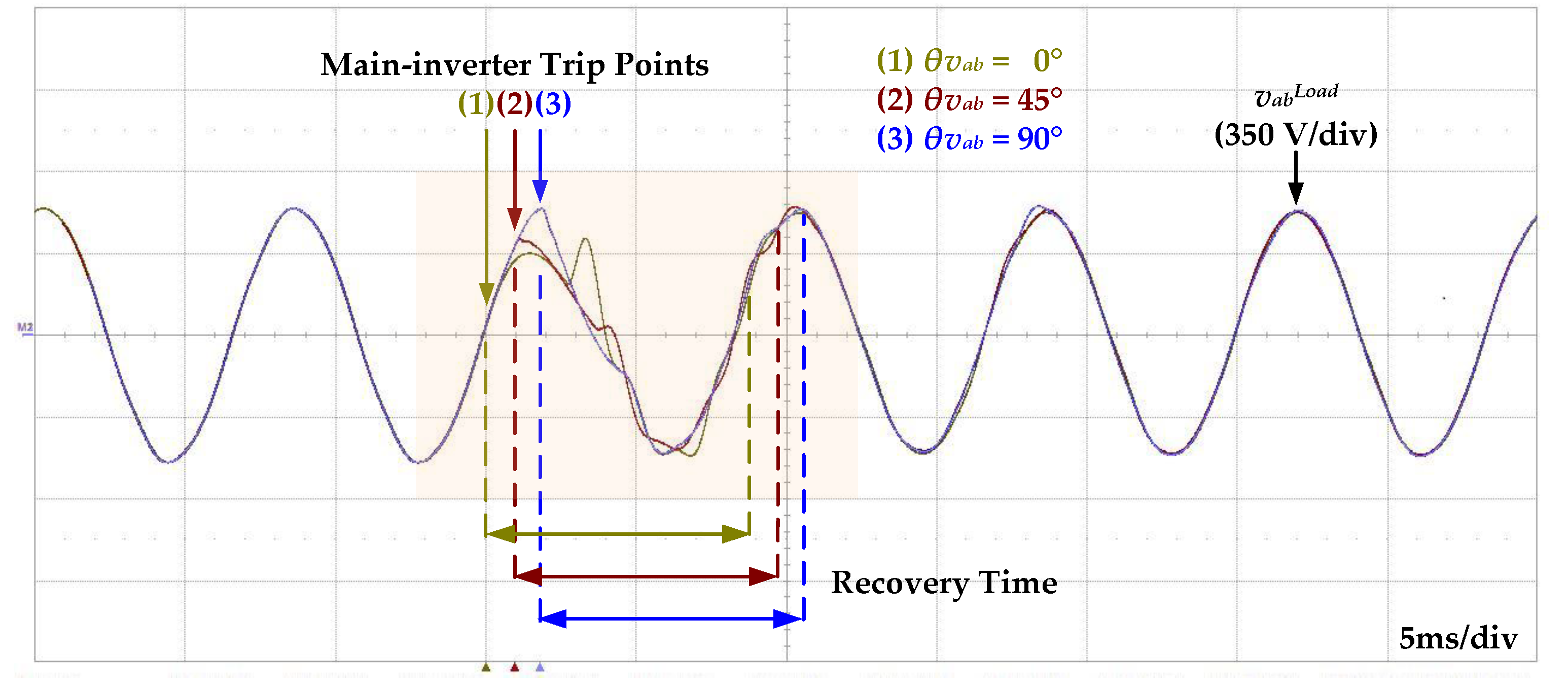
Figure 11 shows the experimental results from Test Conditions 1, 2, and 3 shown in Table 4. The line-to-line voltage of the 3-phase load shows underdamped characteristics when the PWM of the main inverter is stopped. Figure 11a shows that the sub inverter starts operating at 5 ms after the main inverter is stopped at the 0° phase of vab, indicating a fast recovery to the nominal voltage without blackout. Figure 11b,c show similar characteristics when the main inverter is stopped at the 45° and 90° phase values of vab. Figure 12 shows the respective vab waveforms of Test Conditions 1, 2, and 3, which indicate that recovery to the nominal voltage takes place within one cycle from the stopping point of the main inverter PMW.
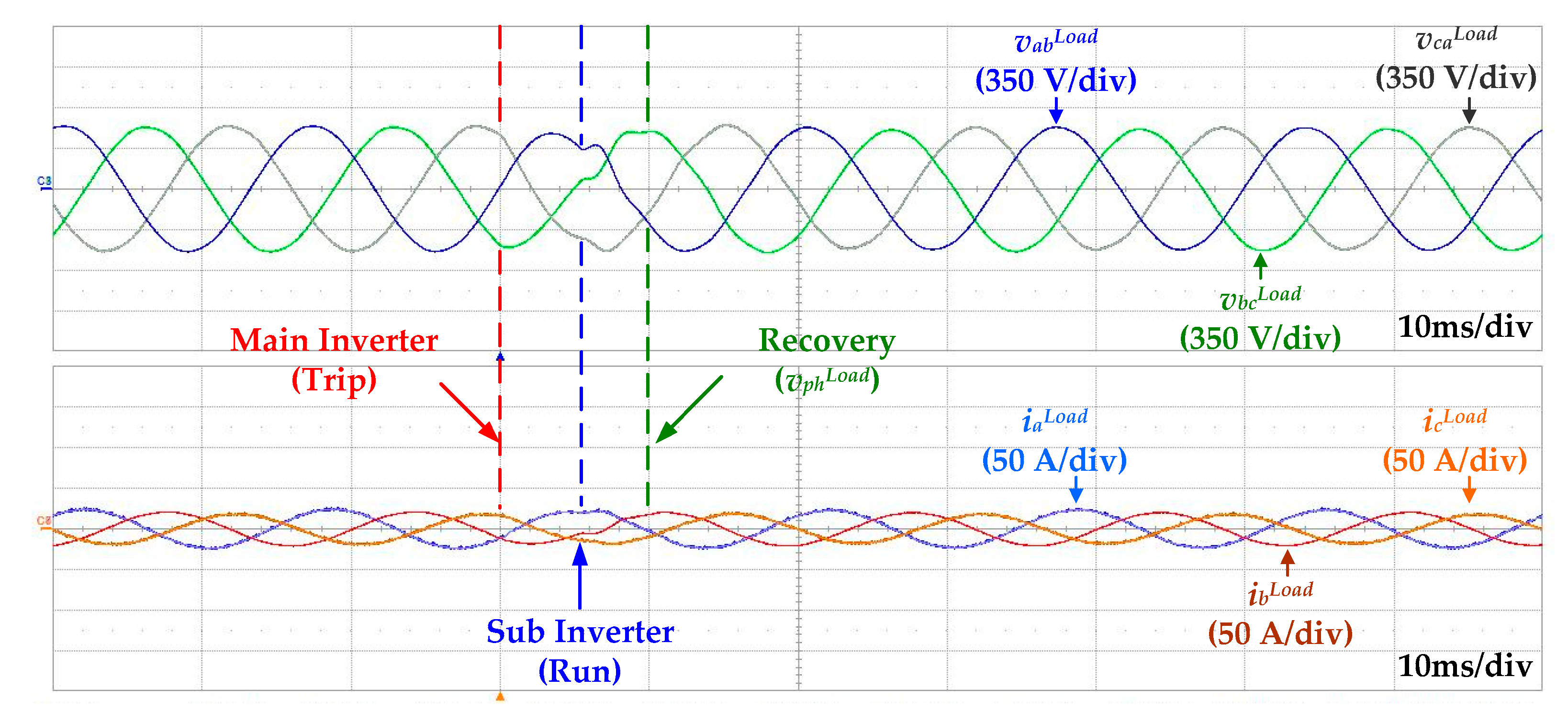
Figure 13 corresponds to the Test Condition 4 in Table 4. The voltage dip at a load of 10 kW is smaller and recovers faster to the nominal voltage as compared to the previous test load of 30 kW. Figure 14 corresponds to Test Condition 5 in Table 4. The ‘soft start’ mode is activated at a load of 80 kW as the LCpL filter is designed to immediately recover to its nominal voltage without generating an inrush current in the transformer up to a load of 30 kW. It was found that the sub inverter could reach the nominal voltage within tens of ms after starting the operation when the load voltage falls below a specific level.
The tests under the above five conditions confirmed that the sub inverter with the designed LCpL filter and under the specified load conditions immediately recovered the voltage without power failure when the main inverter stopped working. Furthermore, it was established that the sub inverter starts in the soft-start mode under all other conditions.
7. Conclusions
In this paper, a method for fast grid voltage recovery was proposed using redundant inverters to ensure high stability in the island microgrid operation in cases where there is a malfunction in the main inverter of the ESS. The voltage dip phenomenon of the microgrid was analyzed when the main inverter of the ESS that is solely responsible for supplying power to the island microgrid unintentionally stopped operating. Based on the above, an LCpL filter design method was proposed wherein the sub inverter could immediately restore the nominal voltage without generating inrush current in the transformer when the main inverter ceased to function below a certain load capacity. Additionally, startup methods and a control algorithm were proposed for the sub inverter based on the designed LCpL filter and load capacity. Experiments were conducted using various loads and two 100 kW inverters with LCpL filters to demonstrate the efficacy of the proposed methods. Several tens of blackout cycles occur to bypass the inrush current when an LC filter is used. Our proposed method facilitates grid recovery within one cycle without any power failure. Thus, this demonstrates that the proposed method improves the stability of a stand-alone microgrid, wherein a high level of stability is required.
Author Contributions
Conceptualization, S.-M.J. and R.-Y.K.; Formal analysis, S.-M.J.; Investigation, S.-M.J., K.-Y.C., S.-H.J. and R.-Y.K.; Methodology, S.-M.J.; Project administration, R.-Y.K.; Software, S.-M.J., K.-Y.C. and S.-H.J.; Validation, S.-M.J.; Visualization, K.-Y.C. and S.-H.J.; Writing – original draft, S.-M.J.; Writing – review & editing, K.-Y.C., S.-H.J. and R.-Y.K.
Funding
This research was supported by the Korea Institute of Energy Technology Evaluation and Planning(KETEP) and the Ministry of Trade, Industry & Energy(MOTIE) of the Republic of Korea (No. 20172410104780)
Conflicts of Interest
The authors declare no conflict of interest.
References
- IEA. World Energy Outlook 2018; IEA: Paris, France, 2018. [Google Scholar]
- REN21. Renewables 2018 Global Status Report; REN21: Paris, France, 2018. [Google Scholar]
- Hatziargyriou, N.; Asano, H.; Iravani, R.; Marnay, C. Microgrids. IEEE Power Energy Mag. 2007, 5, 5–94. [Google Scholar] [CrossRef]
- Olivares, D.E.; Mehrizi-Sani, A.; Etemadi, A.H.; Cañizares, C.A.; Iravani, R.; Kazerani, M.; Hajimiragha, A.H.; Gomis-Bellmunt, O.; Saeedifard, M.; Palma-Behnke, R.; et al. Trend in microgrid control. IEEE Trans. Smart Grid 2014, 5, 1905–1919. [Google Scholar] [CrossRef]
- Nejabatkhah, F.; Li, Y.W. Overview of power management strategies of hybrid AC/DC microgrid. IEEE Trans. Power Electron. 2015, 30, 30–7089. [Google Scholar] [CrossRef]
- Eid, B.M.; Rahim, N.A.; Selvaraj, J.; El Khateb, A.H. Control methods and objectives for electronically coupled distributed energy resources in microgrids: A review. IEEE Syst. J. 2016, 10, 446–458. [Google Scholar] [CrossRef]
- Senjyu, T.; Nakaji, T.; Uezato, K.; Funabashi, T. A hybrid power system using alternative energy facilities in isolated island. IEEE Trans. Energy Convers. 2005, 20, 406–414. [Google Scholar] [CrossRef]
- Nayar, C.; Tang, M.; Suponthana, W. Wind/PV/diesel micro grid system implemented in remote islands in the Republic of Maldives. In Proceedings of the 2008 IEEE International Conference on Sustainable Energy Technologies, Singapore, 24–27 November 2008; pp. 1076–1080. [Google Scholar]
- De Souza Ribeiro, L.A.; Saavedra, O.R.; De Lima, S.L.; De Matos, J.G. Isolated micro-grids with renewable hybrid generation: The case of Lençóis Island. IEEE Trans. Sustain. Energy 2011, 2, 1–11. [Google Scholar] [CrossRef]
- SA Energy Storage 2018: Energy Storage for Robben Island Solar Microgrid. Available online: http://www. energystorage.co.za/energy-storage-robben-island-solar-microgrid (accessed on 23 May 2019).
- ABB: ABB Microgrid Technology to Power Robben Island. Available online: http://www.abb.com/cawp/seitp202/3C283668CC6BDC78482581C5001F7FF7.aspx (accessed on 23 May 2019).
- Ma, Z.; Santos, A.Q.; Gamborg, F.; Nielsen, J.F.; Johannesen, J.M.; Dahl, M.; Jensen, H.; Pedersen, M.R.; Jørgensen, B.N. Solutions for remote island microgrids: Discussion and analysis of Indonesia’s remote island energy system. In Proceedings of the 2018 IEEE Innovative Smart Grid Technologies-Asia (ISGT Asia), Singapore, 22–25 May 2018; pp. 493–498. [Google Scholar]
- Tirumala, R.; Mohan, N.; Henze, C. Seamless transfer of grid-connected PWM inverters between utility-interactive and stand-alone modes. In Proceedings of the APEC Seventeenth Annual IEEE Applied Power Electronics Conference and Exposition, Dallas, TX, USA, 10–14 March 2002; pp. 1081–1086. [Google Scholar]
- Yao, Z.; Wang, Z.; Xiao, L.; Yan, Y. A novel control strategy for grid-interactive inverter in grid-connected and stand-alone modes. In Proceedings of the Twenty-First Annual IEEE Applied Power Electronics Conference and Exposition (APEC ′06), Dallas, TX, USA, 19–23 March 2006. [Google Scholar]
- Jung, S.; Bae, Y.; Choi, S.; Kim, H. Low cost utility interactive inverter for residential fuel cell generation. IEEE Trans. Power Electron. 2007, 22, 2293–2298. [Google Scholar] [CrossRef]
- Kim, H.; Yu, T.; Choi, S. Indirect current control algorithm for utility interactive inverters in distributed generation systems. IEEE Trans. Power Electron. 2008, 23, 1342–1347. [Google Scholar]
- Hwang, T.S.; Park, S.Y. A seamless control strategy of a distributed generation inverter for the critical load safety under strict grid disturbances. IEEE Trans. Power Electron. 2013, 28, 4780–4790. [Google Scholar] [CrossRef]
- Kwon, J.; Yoon, S.; Choi, S. Indirect current control for seamless transfer of three-phase utility interactive inverters. IEEE Trans. Power Electron. 2012, 27, 773–781. [Google Scholar] [CrossRef]
- Liu, Z.; Liu, J.; Zhao, Y. A unified control strategy for three-phase inverter in distributed generation. IEEE Trans. Power Electron. 2014, 29, 1176–1191. [Google Scholar] [CrossRef]
- Fatu, M.; Blaabjerg, F.; Boldea, I. Grid to standalone transition motion-sensorless dual-inverter control of PMSG with asymmetrical grid voltage sags and harmonics filtering. IEEE Trans. Power Electron. 2014, 29, 3463–3472. [Google Scholar] [CrossRef]
- Li, X.; Zhang, H.; Shadmand, M.B.; Balog, R.S. Model predictive control of a voltage-source inverter with seamless transition between islanded and grid-connected operations. IEEE Trans. Ind. Electron. 2017, 64, 7906–7918. [Google Scholar] [CrossRef]
- Das, D.; Gurrala, G.; Shenoy, U.J. Linear quadratic regulator-based bumpless transfer in microgrids. IEEE Trans. Smart Grid 2018, 9, 416–425. [Google Scholar] [CrossRef]
- Guerrero, J.M.; Vicuna, L.G.; Matas, J.; Castilla, M.; Miret, J. Output impedance design of parallel-connected UPS inverters with wireless load-sharing control. IEEE Trans. Ind. Electron. 2005, 52, 1126–1135. [Google Scholar] [CrossRef]
- Guerrero, J.M.; Matas, J.; Vicuna, L.G.; Castilla, M.; Miret, J. Decentralized control for parallel operation of distributed generation inverters using resistive output impedance. IEEE Trans. Ind. Electron. 2007, 54, 994–1004. [Google Scholar] [CrossRef]
- Majumder, R.; Chaudhuri, B.; Ghosh, A.; Majumder, R.; Ledwich, G.; Zare, F. Improvement of stability and load sharing in an autonomous microgrid using supplementary droop control loop. IEEE Trans. Power Syst. 2010, 25, 796–808. [Google Scholar] [CrossRef]
- Bevrani, H.; Shokoohi, S. An intelligent droop control for simultaneous voltage and frequency regulation in islanded microgrids. IEEE Trans. Smart Grid 2013, 4, 1505–1513. [Google Scholar] [CrossRef]
- Han, H.; Liu, Y.; Sun, Y.; Su, M.; Guerrero, J.M. An improved droop control strategy for reactive power sharing in islanded microgrid. IEEE Trans. Power Electron. 2015, 30, 3133–3141. [Google Scholar] [CrossRef]
- Wang, S.; Liu, Z.; Liu, J.; An, R.; Xin, M. Breaking the boundary: A droop and master-slave hybrid control strategy for parallel inverters in islanded microgrids. In Proceedings of the 2017 IEEE Energy Conversion Congress and Exposition (ECCE), Cincinnati, OH, USA, 1–5 October 2017; pp. 3345–3352. [Google Scholar]
- Chen, J.F.; Chu, C.L. Combination voltage-controlled and current-controlled PWM inverters for UPS parallel operation. IEEE Trans. Power Electron. 1995, 10, 547–558. [Google Scholar]
- Lee, W.C.; Lee, T.K.; Lee, S.H.; Kim, K.H.; Hyun, D.S.; Suh, I.Y. A master and slave control strategy for parallel operation of three-phase UPS systems with different ratings. In Proceedings of the Nineteenth Annual IEEE Applied Power Electronics Conference and Exposition, 2004. (APEC ′04.), Anaheim, CA, USA, 22–26 February 2004; pp. 456–462. [Google Scholar]
- Sun, X.; Wong, L.K.; Lee, Y.S.; Xu, D. Design and analysis of an optimal controller for parallel multi-inverter systems. IEEE Trans. Circuits Syst. II Express Briefs 2006, 53, 56–61. [Google Scholar]
- Patel, P.; Naina, S.; Patel, U.; Patwa, P. Load sharing operation in N+1 UPS system by using harmonic sharing control method. In Proceedings of the 2018 International Power Electronics Conference (IPEC-Niigata 2018-ECCE Asia), Niigata, Japan, 20–24 May 2018; pp. 3046–3051. [Google Scholar]
- Polinder, H.; Ferreira, J.A.; Jensen, B.B.; Abrahamsen, A.B.; Atallah, K.; McMahon, R.A. Trends in wind turbine generator systems. IEEE J. Emerg. Sel. Top. Power Electron. 2013, 1, 174–185. [Google Scholar] [CrossRef]
- Specht, T.R. Transformer magnetizing inrush currents. Electr. Eng. 1951, 70, 324. [Google Scholar] [CrossRef]
- Brunke, J.H.; Frohlich, K.J. Elimination of transformer inrush currents by controlled switching. I. Theoretical considerations. IEEE Trans. Power Del. 2001, 16, 276–280. [Google Scholar] [CrossRef]
- Dahono, P.A.; Purwadi, A. An LC filter design method for single-phase PWM inverters. In Proceedings of the 1995 International Conference on Power Electronics and Drive Systems (PEDS 95), Singapore, 21–24 February 1995; pp. 571–576. [Google Scholar]
- Kim, J.; Choi, J.; Hong, H. Output LC filter design of voltage source inverter considering the performance of controller. In Proceedings of the 2000 International Conference on Power System Technology. Proceedings (Cat. No.00EX409), Perth, WA, Australia, 4–7 December 2000; pp. 1659–1664. [Google Scholar]
- Kim, H.; Sul, S.K. Analysis on output LC filters for PWM inverters. In Proceedings of the 2009 IEEE 6th International Power Electronics and Motion Control Conference, Wuhan, China, 17–20 May 2009; pp. 384–389. [Google Scholar]
- Hayt, W.H.; Kemmerly, J.E.; Durbin, S.M. Engineering Circuit Analysis, 7th ed.; McGraw-Hill: New York, NY, USA, 2006; pp. 255–368. [Google Scholar]
Figure 1.
Gapa Island microgrid in South Korea.

Figure 2.
A simplified configuration diagram of the microgrid equipped with an LC filter inverter.

Figure 3.
The waveforms of the grid voltage after inverter shutdown (LC filter-type inverter).

Figure 4.
Load voltage and transformer inrush current waveforms during inverter startup.

Figure 5.
Microgrid voltage fluctuation during the shutdown of the main inverter in the energy storage system (ESS) stand-alone mode (LC filter-type inverter).
Figure 5.
Microgrid voltage fluctuation during the shutdown of the main inverter in the energy storage system (ESS) stand-alone mode (LC filter-type inverter).

Figure 6.
A simplified configuration of the microgrid containing the LCpL filter inverter.

Figure 7.
Microgrid voltage fluctuation during the shutdown of the main inverter in the ESS stand-alone mode (LCpL filter-type inverter).
Figure 7.
Microgrid voltage fluctuation during the shutdown of the main inverter in the ESS stand-alone mode (LCpL filter-type inverter).

Figure 8.
A flowchart showing the operation of the sub inverter.

Figure 9.
Block diagram showing the control algorithm of the sub inverter.

Figure 10.
The test configuration used in our study: (a) Configuration of the experimental setup; (b) Experimental setup.
Figure 10.
The test configuration used in our study: (a) Configuration of the experimental setup; (b) Experimental setup.

Figure 11.
The grid voltage and current waveforms corresponding to the various experiment conditions listed in Table 4: (a) Test Condition 1: Pload = 30 kW, Stop point = vab at phase 0°; (b) Test Condition 2: Pload = 30 kW, Stop point = vab at phase 45°; (c) Test Condition 3: Pload = 30 kW, Stop point = vab at phase 90°.

Figure 12.
Comparison of Test Waveforms under Test Conditions 1, 2 and 3.

Figure 13.
The waveform corresponding to Test Condition 4 (Pload = 10 kW, Stop point = vab at 0°).

Figure 14.
The waveform corresponding to Test Condition 5 (Pload = 80 kW, Stop point = vab at 0°).


Table 1.
The operation mode of a stand-alone microgrid. WT—wind turbine; PV—photovoltaic; SoC—state of charge; ESS—energy storage system.
Table 1.
The operation mode of a stand-alone microgrid. WT—wind turbine; PV—photovoltaic; SoC—state of charge; ESS—energy storage system.
| Amount of Renewable Energy Generation (WT, PV). | Battery SoC | Diesel Generator | ESS Operation |
|---|---|---|---|
| Greater than the Load | SoC ≤ min SoC | Generation | Charge |
| min SoC ≤ SoC ≤ set SoC | - | Charge | |
| set SoC ≤ SoC | - | Charge | |
| Lesser than the Load | SoC ≤ min SoC | Generation | Charge |
| min SoC ≤ SoC ≤ set SoC | Generation | Charge/Discharge | |
| set SoC ≤ SoC | - | Discharge |
Table 2.
Design conditions/parameters.
| Parameter | Value (Unit) |
|---|---|
| Inverter capacity (Pinv) | 100 (kW) |
| Inverter switching frequency (fsw) | 4.2 (kHz) |
| Number of inverters (Ninv) | 2 (Units) |
| Diesel generator capacity (Pdiesel) | 100 (kW) |
| Grid line to neutral voltage (Vr) | 220 (Vrms) |
| Grid frequency (fgrid) | 60 (Hz) |
| Maximum load (Pmax_load) | 50 (kW) |
| Saturation flux density of the transformer (Bs) | 1.88 (Tesla) |
| Flux density (Br) of the transformer at nominal voltage (Br) | 1.21 (Tesla) |
| Transformer turn count (NT) | 32 (turn) |
| Transformer cross section (A) | 0.022 (m2) |
Table 3.
The LfCfpLp filter parameters.
| Parameter | Value (Unit) |
|---|---|
| Filter inductor (Lf) | 0.3 (mH) |
| Filter capacitor (Cf) | 270 (μF) |
| Parallel inductor (Lp) | 20.6 (mH) |
Table 4.
The different test conditions in our study.
| Test Conditions | Filter Type | Load Power (Pload) | Stop Point | Test Result |
|---|---|---|---|---|
| 1 | LCpL filter | 30 kW | vab, 0° | seamless transfer |
| 2 | 30 kW | vab, 45° | seamless transfer | |
| 3 | 30 kW | vab, 90° | seamless transfer | |
| 4 | 10 kW | vab, 0° | seamless transfer | |
| 5 | 80 kW | vab, 0° | soft-start |
© 2019 by the authors. Licensee MDPI, Basel, Switzerland. This article is an open access article distributed under the terms and conditions of the Creative Commons Attribution (CC BY) license (http://creativecommons.org/licenses/by/4.0/).
Share and Cite
MDPI and ACS Style
Jung, S.-M.; Choi, K.-Y.; Jung, S.-H.; Kim, R.-Y. LCpL Filter Design and Control for Stability Improvement in a Stand-Alone Microgrid with Sub Inverter Structure. Energies 2019, 12, 2318. https://0-doi-org.brum.beds.ac.uk/10.3390/en12122318
AMA Style
Jung S-M, Choi K-Y, Jung S-H, Kim R-Y. LCpL Filter Design and Control for Stability Improvement in a Stand-Alone Microgrid with Sub Inverter Structure. Energies. 2019; 12(12):2318. https://0-doi-org.brum.beds.ac.uk/10.3390/en12122318
Chicago/Turabian StyleJung, Sang-Min, Ki-Young Choi, Sang-Hyuk Jung, and Rae-Young Kim. 2019. "LCpL Filter Design and Control for Stability Improvement in a Stand-Alone Microgrid with Sub Inverter Structure" Energies 12, no. 12: 2318. https://0-doi-org.brum.beds.ac.uk/10.3390/en12122318
Note that from the first issue of 2016, this journal uses article numbers instead of page numbers. See further details here.