Modified Electromechanical Modeling and Parameters Analysis of Magnetoplasmadynamic Thruster

College of Aerospace Science and Engineering, National University of Defense Technology, Changsha 410073, China
*
Authors to whom correspondence should be addressed.
Energies 2019, 12(12), 2428; https://0-doi-org.brum.beds.ac.uk/10.3390/en12122428
Submission received: 19 May 2019
/
Revised: 15 June 2019
/
Accepted: 17 June 2019
/
Published: 24 June 2019
(This article belongs to the Section E: Electric Vehicles)
Abstract
:To predict the thrust of magnetoplasmadynamic thrusters (MPDTs), a modified electromechanical model was proposed and a comparison with experimental results is presented in this paper. The motion of propellant in the thruster was divided into two portions: the axial motion which was accelerated by the interaction of current and induced self-field, and the swirling motion which was accelerated by the interaction of current and applied magnetic field. The electromechanical model was in good agreement with the experimental data, and the fitting degrees of the model were greater than 0.93. Furthermore, the influence of parameters on the performance of MPDT were investigated by utilizing the electromechanical model. The results indicate that the thrust performance of the thruster improved with the increase of discharge current, anode radius, applied magnetic field strength, and the decrease of mass flow rate. However, the large anode radius and low mass flow rate readily led to the failure of thruster function. Therefore, the model can not only predict the thrust performance of MPDTs, but also guide the design and operation optimization of the thruster.
1. Introduction
Magnetoplasmadynamic thrusters (MPDTs) are considered as an attractive choice for thrust-demanding space missions, from orbit raising to Mars landing, due to the advantages of low cost, low mass, and high exhaust velocities. As is known, MPDTs with lithium propellants have a higher thrust efficiency, and thrust efficiencies of up to 60% have been recorded [1]. However, thrusters with lithium propellant need a more complicated and power-consuming propellant feed system, and vaporized lithium may damage the surface of the spacecraft due to condensation problems [2]. In light of these considerations, extensive research has been carried out on different propellants [3], geometries [4], and applied magnetic field strengths [5,6] in a broad range of power levels.
Although theoretical and experimental studies on MPDTs have been developed for decades, MPDTs presently remain at the fundamental research stage due to the limiting issues of cathode ablation, “onset” phenomenon, and lifetime. Moreover, the complexity of the interlocking nature involved in MPDT acceleration has not been well identified [7]. Therefore, a phenomenological or semi-empirical model is still required to predict the performance of MPDTs, and reveal the effect of several parameters (e.g., discharge current and applied magnetic field strength) on the thrust performance. To date, several theoretical models have been established for both self-field MPDTs (SF-MPDTs) [2,8,9] and applied-field MPDTs (AF-MPDTs) [5,6,10,11,12,13,14,15].
The thrust formula of SF-MPDTs, based on the Maecker’s relation, can be expressed as [10]
The theoretical models of AF-MPDTs have recently been discussed in detail [11,12]. Coletti [11], of the Tony Davies High Voltage Laboratory (TDHVL), analyzed the mechanism of swirling velocity converting to axial velocity into the magnetic nozzle, and developed a thrust formula to predict the thrust of AF-MPDTs. In order to validate the thrust formula, the predicted values of swirling angular velocity, thrust, and specific impulse were compared with experimental data from 5 thrusters. The results showed that the prediction of TDHVL’s thrust formula was reasonable within a wide range of operational conditions. Otherwise, Albertoni [12] of Alta SPA proposed a phenomenological performance model for AF-MPDTs to estimate the thrust and terminal voltage, and then a systematic comparison between the model and the experimental data was made to assess the validity of the model. The results showed that Alta’s model can actually capture most of the characteristics of 100 kW AF-MPDTs within a 20% error. However, both of the above models are developed only for AF-MPDTs, and tend to overestimate the experimental data at high current levels. In other words, the accuracy of above models can be further improved.
In this study, a modified electromechanical model for MPDTs (SF-MPDT, gas-fed, and lithium propellant AF-MPDT) is presented, and the mechanism of energy conversion and acceleration in the thruster is discussed. Then, the effects of parameters on the thrust performance of MPDT are analyzed, utilizing the model. The purpose of this work is to develop a widely applicable model able to predict the thrust performance of MPDTs, and guide the design and operation optimization of the thruster.
The remainder of the paper is organized as follows. Section 2 presents the theoretical modeling process of the modified electromechanical model. Section 3 compares the numerical results with the experimental results and previous models, which verifies the effectiveness of the theoretical modeling. Section 4 explores the influences of different parameters on the thrust performance of MPDT. Finally, some conclusive remarks are given in Section 5.
2. Model Description
In general, the MPDT is made of a central cathode and a concentric anode. The propellant is ionized and then accelerated by the high-current arc between the electrodes. In the thruster, the ionized propellant is accelerated by the Lorentz force, and then ejects from the thruster with high speed (10 km/s), thus forming the thrust as shown in Figure 1. In an MPDT, the induced azimuthal magnetic field Bsf is produced by discharge current, and the axial applied magnetic field Bap is produced by the electromagnetic coils around the outside of the anode. The interactions between the magnetic field and current mainly produce two force components: azimuthal () and axial (), because the radial current is dominant in comparison with the axial and azimuthal components [16].
The acceleration of ionized propellant in the thruster is considered as the motion of continuous current sheets, as shown in Figure 2. The motion of the current sheets can be divided into two portions, the axial motion driven by axial thrust Fsf and the swirling motion driven by azimuthal thrust .
The electromechanical model is developed based on macroscopic interaction of the MPDT and, hence, several hypotheses follow:
- (1)
- The acceleration of propellant can be considered as the motion of continuous current sheets in the thruster.
- (2)
- The magnetic lines of an applied field are parallel to the axis of the thruster.
- (3)
- The current I into the thruster is uniform.
- (4)
- The particles in the thruster are fully ionized.
- (5)
- The azimuthal and axial components of the total current are neglected in comparison with the radial one in the thruster.
- (6)
- The gas dynamic thrust is neglected in comparison with the electromagnetic one.
2.1. Axial Motion
The axial motion of the current sheet in the thruster is dynamically described by Newton’s second law:
Equation (3) can be transformed into the first-order differential equations
where and .
The initial condition of Equation (4) is
The current density j can be expressed as
Substituting (7) and (8) into (6) yields
2.2. Swirling Motion
The swirling motion of the current sheets in the thruster can be expressed as
where J(t) and is variational at different axial position because of the flared anode.
The moment of inertia J(t) can be expressed as
The swirling torque can be expressed as [17]
At the exit of the thruster, the azimuthal kinetic energy is partially converted into axial kinetic energy due to the effect of the magnetic nozzle [17,18]. The total thrust of the MPDT can be expressed as
where is in a range of 0~1. In this study, is equal to 0.5 for gas-fed propellant AF-MPDTs, while it is equal to 0.7 for lithium propellant AF-MPDTs.
The Vsf can be obtained through solving the axial motion Equation (3).
The Vsf can be expressed as
where is obtained through solving the swirling motion Equation (10).
This electromechanical model divides the motion in the thruster into two portions, which are axial and swirling motions, respectively. The axial motion is produced by the interaction of radial current jr and induced azimuthal magnetic field Bsf. The swirling motion is produced by the interaction of radial current jr and applied magnetic field Bap. For SF-MPDTs, Bap = 0 and the motion in the thruster is only driven by axial thrust Fsf. Therefore, Equation (13) can be written as
Thus, this electromechanical model is suitable for both SF-MPDTs and AF-MPDTs.
3. Comparison with Experiments and Previous Models
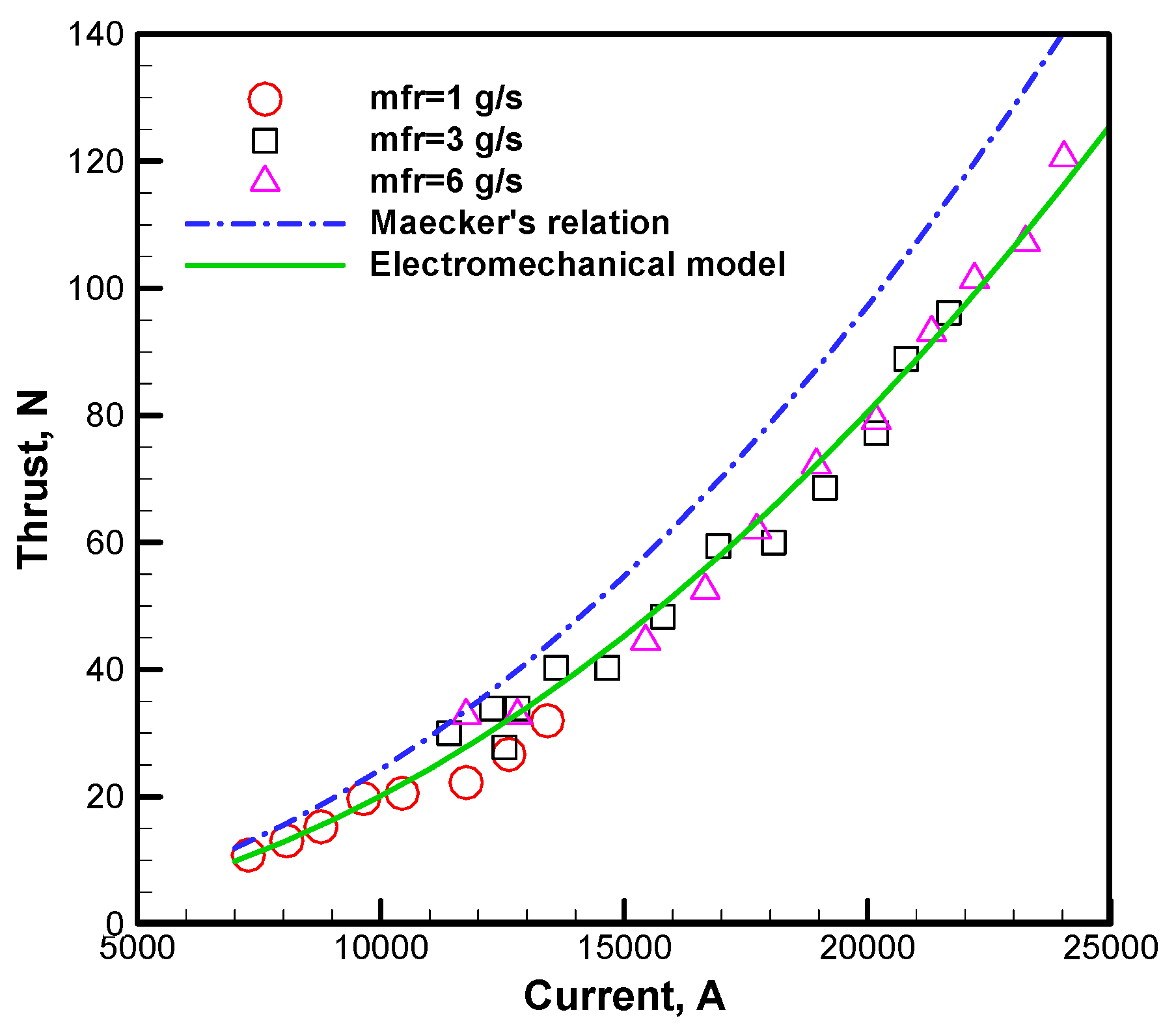
Princeton’s full-scale benchmark thruster (FSBT) is an axisymmetric SF-MPDT with a central cathode and a coaxial anode. The thoriated tungsten cathode is used, with an outer diameter of 1.9 cm and length of 10 cm. The anode is an annular aluminum disk with an inner diameter of 10.2 cm. The propellant is injected through multiple orifices. Fifty-four percent of the mass flow rate goes through an annulus around the cathode base, and the rest goes through a ring of 12 holes in the backplate. The thruster is bolted to the plate of the thrust stand for thrust measurement, and the thruster is operated from hundreds of kW to several MW with a current pulse width of about 1 ms [3].
The thrust of the SF-MPDT is calculated according to the electromechanical model, which is compared with the experimental data at different mass flow rates and currents, as plotted in Figure 3. In Maecker’s relation, the effect of mass flow rate on the thrust is omitted. Similarly, the results reported in Figure 3 demonstrate that the thrust is relatively independent of the mass flow rate for the electromechanical model and the Princeton experimental data. However, the mass flow rate determines the “onset” current, which increases with the increase of mass flow rate. In general, the electromechanical model is in better accordance with the experimental data than Maecker’s relation. Maecker’s relation tends to overestimate the experimental data, especially at high current levels.
The fitting degree Rnew is introduced to reveal the correlation between the calculated results and the experimental data, and it can be defined as
where is the experimental values, and is the calculated value.
The Rnew varies from 0 to 1, and the closer the Rnew is to 1, the better the theoretical model is in accordance with the experimental data. In general, it is considered that the theoretical model is in good accordance with the experimental data when the Rnew is greater than 0.9.
The Rnew values of Maecker’s relation and the electromechanical model are, respectively, 0.7213 and 0.9479, which indicate that the electromechanical model is better than the Maecker’s relation for the thrust prediction of SF-MPDTs.
3.1. Comparison with AF-MPDT
3.1.1. Gas-Fed Propellant Thruster
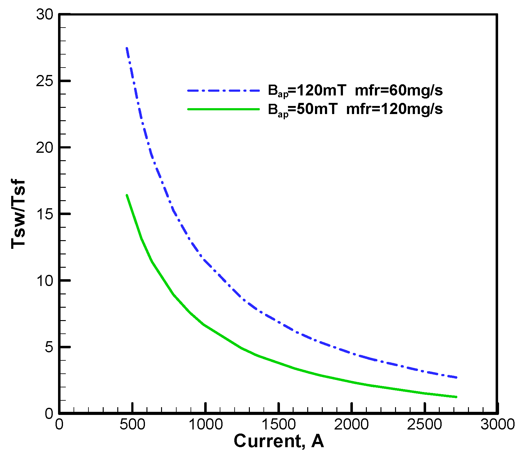
The Alta 100 kW thruster is an axisymmetric AF-MPDT with a central multichannel hollow cathode and a coaxial flared anode. A 40 mm inner diameter and 2 mm thickness molybdenum alloy (TZM) cathode are used, and 330 W–La rods of 2 mm diameter and 40 mm length each are tightly packed inside the cathode. The packing porosity of the cathode is approximately 17%. An oxygen-free copper (OFC) anode with a minimum diameter of 100 mm is slightly divergent (°). A 430-turn external coaxial solenoid around the anode is capable of generating a magnetic field strength up to 130 mT with a current of about 60 A. The thruster is operated from 25 to 200 kW using argon propellant with current pulse width of 500 ms. The mass flow rate of 60 and 120 mg/s and applied magnetic field strength of 50 and 120 mT are experimentally studied, respectively [19].
In order to validate the electromechanical model, the predicted results are compared with experimental data of Alta 100 kW thruster, and the Alta’s thrust relation described in literature [12]. The results plotted in Figure 4 indicate that both the electromechanical model and Alta’s thrust relation can match well with the experimental data of the Alta 100 kW thruster. However, Alta’s thrust relation tends to overestimate the experimental data at high current levels. The electromechanical model is found to fit better to the variation tendency of the experimental data. The fitting degree, Rnew, of the electromechanical model with the experimental data is 0.932 at a mass flow rate of 120 mg/s and the applied magnetic field strength of 50 mT, while it is 0.9841 at a mass flow rate of 60 mg/s and the applied magnetic field strength of 120 mT.
The swirl to self-field thrust ratios of the Alta 100 kW thruster are listed in Figure 5. The results showed that the value of Tsw/Tsf decreases from 27.5 to 2.7 with current increasing from 460 to 2700 A for Bap = 120 mT, and it decreases from 16.4 to 1.3 for Bap = 50 mT. Moreover, the values of Tsw/Tsf increase with the increase of applied magnetic field strength, and decrease with current increase, but the variation rate decreases with the current increase. Compared with the value of Tsw/Tsf recorded in the literature [12], Figure 5 can better explain the effect of applied magnetic field strength on the thrust performance of AF-MPDT. The swirl thrust Tsw increases linearly with the applied magnetic field strength [20], therefore, the value of Tsw/Tsf increases with the increase of applied magnetic field strength. However, the self-field thrust Tsf increases linearly with the square of current [16], therefore, the value of Tsw/Tsf decreases with the current increase, and the variation rate decreases. In a word, the applied magnetic field strength greatly affects the thrust performance of AF-MPDT, especially at low current levels. However, the effect tends to reduced with an increase of current.
3.1.2. Lithium Propellant Thruster
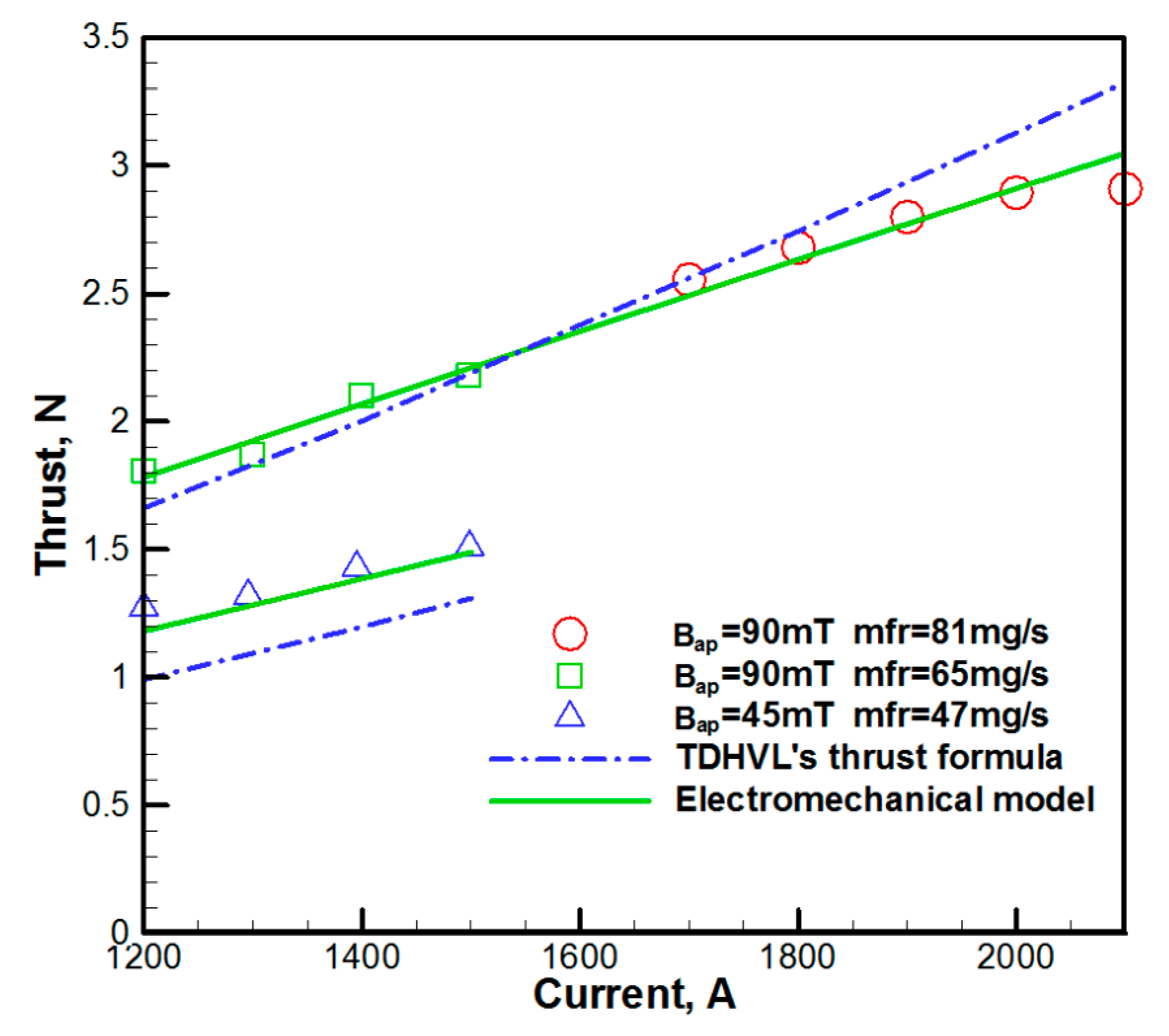
The MAI 130KW thruster is an axisymmetric AF-MPDT with a central multichannel hollow cathode and flared anode. The used cathode is 45 mm in diameter and contains a bundle of tungsten rods. The tungsten anode has an outlet diameter of 160 mm. The external coaxial solenoid is capable of producing an induced magnetic field strength up to 130 mT. The thruster is operated using lithium propellant at mass flow rates within the range from 45 to 95 mg/s, current from 1200 to 2100 A, and applied magnetic field strength of 45 and 90 mT [21].
In order to validate the electromechanical model, the predicted results are compared with the experimental data of MAI 130 KW thruster, and the TDHVL’s thrust formula as described in the literature [11]. The results illustrated in Figure 6 indicate that the thrust is relatively independent of mass flow rate for the electromechanical model and the TDHVL’s thrust formula. Both the electromechanical model and the TDHVL’s thrust formula can provide a good fit to the experimental data of the MAI 130KW thruster in the case of 90 mT. However, the electromechanical model tends to give more accurate predictions at low and high current levels than TDHVL’s thrust formula. The consistency of the electromechanical model and experimental data are reasonable in the 45 mT case, whereas the TDHVL’s thrust formula underestimates the measurements. The fitting degree, Rnew, of the electromechanical model with the experimental data is 0.9757 at Bap = 90 mT, and 0.9589 at Bap = 45 mT. Thus, the electromechanical model can accurately predict the thrust performance of MAI 130KW thruster. The swirl to self-field thrust ratios of the MAI 130KW thruster are calculated and plotted in Figure 7. The results showed that the value of Tsw/Tsf decreases from 13 to 6.8 with the current increasing from 1200 to 2200 A at Bap = 90 mT, while it decreases from 8.3 to 4.4 at Bap = 45 mT.
4. Parameters Analysis
The parameters affecting the performance of MPDT mainly include discharge parameters (e.g., discharge current), structural parameters (e.g., anode radius), and working parameters (e.g., mass flow rate and applied magnetic field strength). Utilizing the electromechanical model, the effects of parameters on the performance of MPDT were numerically investigated. The calculated cases are listed in Table 1.
In order to quantitatively analyze the effects of parameters on the thrust performances of MPDT, several calculated formulas of the thrust performance were designed.
where is mass flow rate and V is the velocity of current sheet.
where Pin is the input power of the thruster.
4.1. Discharge Current
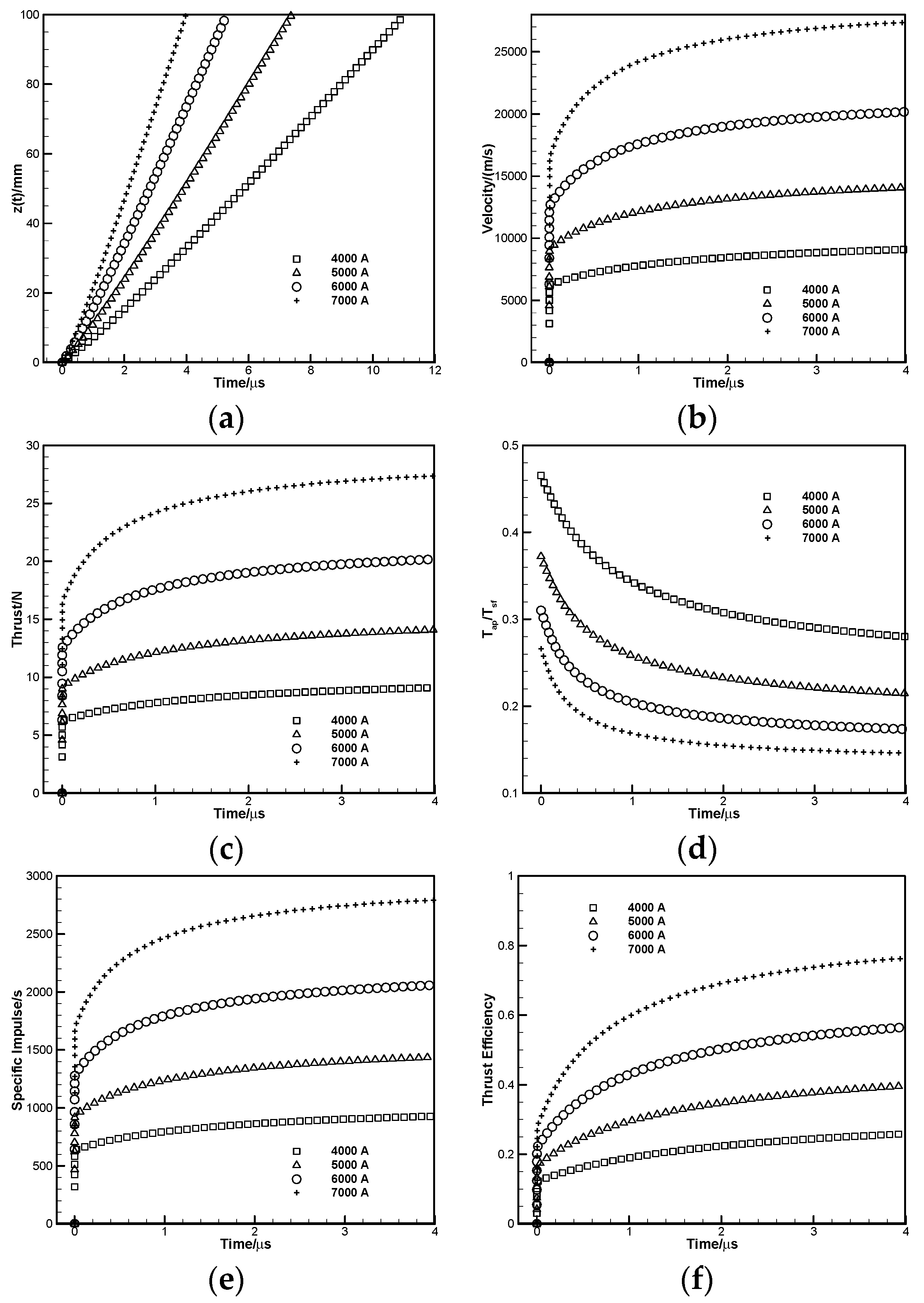
Discharge current directly determines the power consumption of the thruster. With the increase of discharge current, more electric energy is deposited into the discharge arc between the anode and the cathode of the thruster. Therefore, as the discharge current increases, the induced magnetic field strength increases and, thus, the Lorentz force acting on the plasma increases.
Figure 8 shows the effects of discharge current on thrust performances. It can be concluded from Figure 8a that the response time of the thruster is very fast, and the thruster can output thrust within a very short time (μs) after the discharge starts. The working response of the thruster is more rapid with the increase of discharge current. As shown in Figure 8b, the velocity of current sheet increases rapidly after the discharge starts, but the growth rate decreases gradually with time, and the velocity of current sheet tends to be stable. The variation trend of thrust with the discharge current is consistent with the velocity of current sheet, as shown in Figure 8c. Figure 8d shows that the ratio of applied-field thrust to self-field thrust decreases with time, and gradually tends to stability. The self-field thrust increases with the increase of discharge current, which is produced by the interaction between discharge current and induced self-field. Meanwhile, the applied-field thrust also increases with the increase of discharge current, which is produced by the interaction between discharge current and applied-field. The ratio of applied-field thrust to self-field thrust decreases as discharge current increasing, which indicates that the discharge current affects the thrust mainly by increasing the self-field thrust. It can be obtained from Equation (18) that the variation of specific impulse with the discharge current is consistent with the velocity of current sheet, as shown in Figure 8e. According to Equation (19), the thrust efficiency is proportional to the square of thrust and inversely proportional to the input power, as shown in Figure 8f.
4.2. Anode Radius
Anode radius is one of the important structural parameters of thruster. Changing the anode radius can not only directly affect the discharge characteristics of thruster but also change the distribution and strength of self-induced magnetic field, and then affect the self-field thrust. Meanwhile, anode radius also determines the inertia of the current sheet, and thus affects the applied-field thrust.
Figure 9 shows the effects of anode radius on thrust performances. According to Figure 9a, the working response of the thruster decreases with the increase of the anode radius. The velocity of the current sheet and thrust increase as the anode radius increasing, as shown in Figure 9b,c. It can be seen from Figure 9d that the ratio of applied-field thrust to self-field thrust increases with the increase of the anode radius, which indicates that the effect of the anode radius on the applied-field thrust is more significant. As shown in Figure 9e,f, the specific impulse and thrust efficiency increases as the anode radius increases, which means increasing the anode radius can improve the thrust performance of thruster. However, in practice, the anode radius cannot be increased infinitely. With the increase of the anode radius, the distance between the anode and cathode increases, and the difficulty of forming breakdown between the electrodes of thruster increases accordingly. Hence, higher breakdown voltage and induced plasma density are needed, which brings more difficulties to the design of the thruster.
4.3. Mass Flow Rate
The mass flow rate can directly affect the quality of the current sheet in the electromechanical model and then affect the thrust performance.
Figure 10 shows the effects of mass flow rate on thrust performances. According to Figure 10a, with the increase of mass flow rate, the mass of current sheet increases and, hence, the time of current sheet reaching the outlet of thruster increases, which means the working response time of the thruster increases gradually. The change of mass flow rate cannot affect the distribution of electromagnetic field in the thruster, that is, the force of current sheet will not change with mass flow rate increasing. Therefore, the velocity of current sheet decreases with the increase of mass flow rate, as shown in Figure 10b. It can be obtained from Equation (17) that the thrust is proportional to the mass flow rate and the velocity of current sheet, while the velocity of current sheet is inversely proportional to the mass flow rate. As shown in Figure 10c, the influence of mass flow rate on thrust is weak, and the thrust decreases slightly with the increase of mass flow rate. Figure 10d shows that the ratio of applied-field thrust to self-field thrust increases slightly with the increase of the mass flow rate. It has been known that the thrust decreases with the increase of mass flow rate, while the ratio of applied-field thrust to self-field thrust increases with the increase of mass flow rate, which indicates that the effect of mass flow rate on the applied-field thrust is more significant. According to Equation (18), the variation of specific impulse with mass flow rate is consistent with the velocity of current sheet, as shown in Figure 10e. The change of mass flow rate cannot affect the input power of thruster. Therefore, from Equation (19), it can be concluded that the thrust efficiency is proportional to the square of thrust and inversely proportional to mass flow rate. In has been known that the thrust decreases slightly with the increase of mass flow rate and, hence, the thrust efficiency inevitably decreases with the increase of mass flow rate, as shown in Figure 10f. However, in practice, the low mass flow rate can easily lead to the insufficient plasma density of induced breakdown in the thruster, and then lead to the failure of thruster function.
4.4. Applied Magnetic Field Strength
The angular force acting on the current sheet is produced by the interaction between the applied magnetic field and discharge current, and the angular momentum is then converted into the axial momentum through the expanding “magnetic nozzle”.
Figure 11 shows the effects of the applied magnetic field strength on thrust performances. With the increase of applied magnetic field strength, the applied-field thrust increases, then the working response, velocity of current sheet, thrust, ratio of applied-field thrust to self-field thrust, specific impulse, and thrust efficiency increase, as shown in Figure 11a–f. However, in practice, the applied magnetic field strength is usually generated by the coil current around the outer side of the thruster. Therefore, in order to obtain a greater applied magnetic field strength, a larger coil current is needed, and the input power of coil current needs to be increased. Otherwise, the increase of coil current requires a larger core diameter of the conductor, which increases the quality of the whole thruster.
5. Conclusions
A modified electromechanical model is developed and validated in this paper. The acceleration of propellant in the thruster is considered as the motion of continuous current sheet, and divided into two portions, which are axial and swirling motions. The axial motion is accelerated by axial thrust Fsf which is produced by the interaction of radial current jr and induced azimuthal magnetic field Bsf. The swirling motion is accelerated by azimuthal thrust which is produced by the interaction of radial current jr and axial applied magnetic field Bap. Then, the thrust performances calculated by the electromechanical model are compared with the experimental data of SF-MPDTs and gas-fed and lithium propellant AF-MPDTs. Utilizing this model, the effects of parameters on thrust performances were numerically investigated. The following achievements and conclusions are summarized.
- (1)
- The electromechanical model is suitable for SF-MPDTs, and gas-fed and lithium propellant AF-MPDTs. The fitting degrees (Rnew) of the electromechanical model with the experimental data of different thrusters are all greater than 0.93, which means the calculated results are in good agreement with the experimental results.
- (2)
- With the increase of discharge current, the working response, velocity of current sheet, thrust, specific impulse, and thrust efficiency increase, but the ratio of applied-field thrust to self-field thrust decreases. The results indicate that the discharge current improves the thrust performance of thruster mainly by increasing the self-field thrust, which means the thruster can obtain better performance under the condition of high-power operation.
- (3)
- With the increase of anode radius, the working response, velocity of current sheet, thrust, ratio of applied-field thrust to self-field thrust, specific impulse, and thrust efficiency increase. The results show that increasing the anode radius can improve the thrust performance of thruster, but increasing the anode radius will also increase the threshold voltage of breakdown of the thruster.
- (4)
- With the increase of mass flow rate, the working response, velocity of current sheet, thrust, specific impulse, and thrust efficiency decreases, but the ratio of applied-field thrust to self-field thrust increases. The results indicate that the thrust performance of thruster reduces as the mass flow rate increases. However, the low mass flow rate can easily lead to the failure of the thruster, due to the insufficient plasma density of induced breakdown discharge.
- (5)
- With the increase of applied magnetic field, the working response, velocity of current sheet, thrust, ratio of applied-field thrust to self-field thrust, specific impulse, and thrust efficiency increase. The results show that the applied magnetic field can significantly improve the thrust performance of the thruster.
Author Contributions
Y.Z. established the theoretical model; J.W. and Y.O. analyzed the data; J.L. and S.T. provided reagents/materials/analysis tools; Y.Z. wrote the paper.
Funding
Chinese National Natural Science Foundation: 11772354.
Acknowledgments
This work was supported by Chinese National Natural Science Foundation (11772354).
Conflicts of Interest
The authors declare no conflict of interest.
Nomenclature
| Nomenclature | |
| B | magnetic field, T |
| F | force, N |
| f | force per unit volume, |
| I | current, A |
| j | current density, |
| L | length of the thruster, m |
| m | mass of the current sheet, kg |
| mass flow rate, kg/s | |
| M | torque, |
| R | radius, m |
| Rnew | fitting degree |
| t | time, s |
| T | thrust, N |
| V | velocity, m/s |
| cylindrical coordinate | |
| displacement of current sheet in axial direction, m | |
| angular velocity, rad/s | |
| vacuum magnetic permeability, | |
| fraction of azimuthal velocity converted into axial velocity | |
| Subscript | |
| a | anode |
| ap | with applied field |
| c | cathode |
| sf | self-field |
| sw | swirling |
| tot | total |
| direction | |
References
- Kodys, A.D.; Choueiri, E.Y. A Critical Review of the State-of-the-Art in the Performance of Applied-Field Magnetoplasmadynamic Thrusters; AIAA 2005-4247; American Institute of Aeronautics and Astronautics: Reston, VA, USA, 2005. [Google Scholar]
- Xisto, C.M.; Páscoa, J.C.; Oliveira, P.J. Numerical analysis of real gas MHD flow on two-dimensional self-field MPD thrusters. Acta Astronaut. 2015, 112, 89–101. [Google Scholar] [CrossRef]
- Choueiri, E.Y.; Ziemer, J.K. Quasi-steady magnetoplasmadynamic thruster performance database. J. Propuls. Power 2001, 17, 967–976. [Google Scholar]
- Myers, R.M. Geometric scaling of applied-field magnetoplasmadynamic thrusters. J. Propuls. Power 1995, 11, 343–350. [Google Scholar] [CrossRef]
- Mikellides, P.G.; Turchi, P.J.; Roderick, N.F. Applied-field magnetoplasmadynamic thrusters, Part 1: Numerical simulations using the MACH2 code. J. Propuls. Power 2000, 16, 887–893. [Google Scholar] [CrossRef]
- Mikellides, P.G.; Turchi, P.J. Applied-field magnetoplasmadynamic thrusters, Part 2: Analytic expressions for thrust and voltage. J. Propuls. Power 2000, 16, 894–901. [Google Scholar] [CrossRef]
- Ahangar, M.; Ebrahimi, R.; Shams, M. Numerical investigation of plasma behavior and anode sheath in a magnetoplasmadynamic Thruster. J. Propuls. Power 2016, 32, 420–430. [Google Scholar] [CrossRef]
- Gilland, J.; Johnston, G. MPD thruster performance analytic models. AIP Conf. Proc. 2003, 654, 516–524. [Google Scholar]
- Guarducci, F.; Paccani, G.; Lehnert, J. Quasi steady MPD performance analysis. Acta Astronaut. 2011, 68, 904–914. [Google Scholar] [CrossRef]
- Jahn, R.G. Physics of Electric Propulsion; McGraw-Hill: New York, NY, USA, 1968. [Google Scholar]
- Coletti, M. A thrust formula for an MPD thruster with applied-magnetic field. Acta Astronaut. 2012, 81, 667–674. [Google Scholar] [CrossRef]
- Albertoni, R.; Paganucci, F.; Andrenucci, M. A phenomenological performance model for applied-field MPD thrusters. Acta Astronaut. 2015, 107, 177–186. [Google Scholar] [CrossRef]
- Tikhonov, V.B.; Semenikhin, S.A.; Alexandrov, V.A.; Dyakonov, G.; Popov, G. Research on plasma acceleration processes in self-field and applied magnetic field thrusters. In Proceedings of the 23rd International Electric Propulsion Conference, Seattle, WA, USA, 16 September 1993. [Google Scholar]
- Li, Z.; Tang, H.; Wang, Y.; Wang, B.; Lu, X.; Zhang, Z. Increasing the effective voltage in applied-field MPD thrusters. J. Phys. D Appl. Phys. 2018, 51, 085201. [Google Scholar] [CrossRef]
- Wang, B.; Yang, W.; Tang, H.; Li, Z.; Kitaeva, A.; Chen, Z.; Cao, J.; Herdrich, G.; Zhang, K. Target thrust measurement for applied-field magnetoplasmadynamic thruster. Meas. Sci. Technol. 2018, 29, 075302. [Google Scholar] [CrossRef]
- Tang, H.B.; Cheng, J.; Liu, C.; York, T.M. Study of applied magnetic field magnetoplasmadynamic thrusters with particle-in-cell and monte carlo collision. II. Investigation of acceleration mechanisms. Phys. Plasmas 2012, 19, 1–11. [Google Scholar] [CrossRef]
- Kagaya, Y.; Tahara, H. Swirl acceleration in a quasi-steady MPD thruster by applied magnetic nozzle. In Proceedings of the 29th International Electric Propulsion Conference, Princeton, NJ, USA, 29 October 2005. [Google Scholar]
- Li, M.; Tang, H.B.; Ren, J.X.; York, T.M. Modeling of plasma processes in the slowly diverging magnetic fields at the exit of an applied-field magnetoplasmadynamic thruster. Phys. Plasmas 2013, 20, 1–13. [Google Scholar] [CrossRef]
- Albertoni, R.; Paganucci, F.; Rossetti, P.; Andrenucci, M. Experimental study of a hundred-kilowatt-class applied-field magnetoplasmadynamic thruster. J. Propuls. Power 2013, 29, 1138–1145. [Google Scholar] [CrossRef]
- Lev, D.R.; Choueiri, E.Y. Scaling of efficiency with applied magnetic field in magnetoplasmadynamic thrusters. J. Propuls. Power 2012, 28, 609–616. [Google Scholar] [CrossRef]
- Tikhonov, V.B.; Semenikhin, S.A.; Brophy, J.R.; Polk, J.E. Performance of 130 KW MPD thruster with an external magnetic field and li as a propellant. In Proceedings of the 25th International Electric Propulsion Conference, Cleveland, HI, USA, 25 October 1997. [Google Scholar]
Figure 1.
Magnetoplasmadynamic thruster (MPDT) schematic with applied and induced fields and currents and electromagnetic forces.
Figure 1.
Magnetoplasmadynamic thruster (MPDT) schematic with applied and induced fields and currents and electromagnetic forces.

Figure 2.
Elements of the electromechanical model.

Figure 3.
Variations of theoretical and experimental thrust with currents.

Figure 4.
Variations of theoretical and experimental thrust with currents.

Figure 5.
Variations of swirls to self-field thrust ratio with currents.

Figure 6.
Variations of theoretical and experimental thrust with currents.

Figure 7.
Variations of swirls to self-field thrust ratio with currents.

Figure 8.
Effects of discharge current on thrust performances: (a) Axial movement of current sheet; (b) Velocity of current sheet; (c) Thrust; (d) Ratio of applied-field thrust to self-field thrust; (e) Specific impulse; (f) Thrust efficiency.
Figure 8.
Effects of discharge current on thrust performances: (a) Axial movement of current sheet; (b) Velocity of current sheet; (c) Thrust; (d) Ratio of applied-field thrust to self-field thrust; (e) Specific impulse; (f) Thrust efficiency.

Figure 9.
Effects of anode radius on thrust performances: (a) Axial movement of current sheet; (b) Velocity of current sheet; (c) Thrust; (d) Ratio of applied-field thrust to self-field thrust; (e) Specific impulse; (f) Thrust efficiency.
Figure 9.
Effects of anode radius on thrust performances: (a) Axial movement of current sheet; (b) Velocity of current sheet; (c) Thrust; (d) Ratio of applied-field thrust to self-field thrust; (e) Specific impulse; (f) Thrust efficiency.

Figure 10.
Effects of mass flow rate on thrust performances: (a) Axial movement of current sheet; (b) Velocity of current sheet; (c) Thrust; (d) Ratio of applied-field thrust to self-field thrust; (e) Specific impulse; (f) Thrust efficiency.
Figure 10.
Effects of mass flow rate on thrust performances: (a) Axial movement of current sheet; (b) Velocity of current sheet; (c) Thrust; (d) Ratio of applied-field thrust to self-field thrust; (e) Specific impulse; (f) Thrust efficiency.


Figure 11.
Effects of applied magnetic field strength on thrust performances: (a) Axial movement of current sheet; (b) Velocity of current sheet; (c) Thrust; (d) Ratio of applied-field thrust to self-field thrust; (e) Specific impulse; (f) Thrust efficiency.
Figure 11.
Effects of applied magnetic field strength on thrust performances: (a) Axial movement of current sheet; (b) Velocity of current sheet; (c) Thrust; (d) Ratio of applied-field thrust to self-field thrust; (e) Specific impulse; (f) Thrust efficiency.


Table 1.
Calculated cases.
| Order | Current I/A | Anode Radius (mm) | Mass Flow Rate (g/s) | Applied Magnetic Field Strength (mT) |
|---|---|---|---|---|
| 1 | 4000 | 15 | 1 | 100 |
| 2 | 5000 | 15 | 1 | 100 |
| 3 | 6000 | 15 | 1 | 100 |
| 4 | 7000 | 15 | 1 | 100 |
| 5 | 5000 | 10 | 1 | 100 |
| 6 | 5000 | 20 | 1 | 100 |
| 7 | 5000 | 25 | 1 | 100 |
| 8 | 5000 | 15 | 0.5 | 100 |
| 9 | 5000 | 15 | 1.5 | 100 |
| 10 | 5000 | 15 | 2.0 | 100 |
| 11 | 5000 | 15 | 1 | 50 |
| 12 | 5000 | 15 | 1 | 200 |
| 13 | 5000 | 15 | 1 | 300 |
© 2019 by the authors. Licensee MDPI, Basel, Switzerland. This article is an open access article distributed under the terms and conditions of the Creative Commons Attribution (CC BY) license (http://creativecommons.org/licenses/by/4.0/).
Share and Cite
MDPI and ACS Style
Zhang, Y.; Wu, J.; Ou, Y.; Li, J.; Tan, S. Modified Electromechanical Modeling and Parameters Analysis of Magnetoplasmadynamic Thruster. Energies 2019, 12, 2428. https://0-doi-org.brum.beds.ac.uk/10.3390/en12122428
AMA Style
Zhang Y, Wu J, Ou Y, Li J, Tan S. Modified Electromechanical Modeling and Parameters Analysis of Magnetoplasmadynamic Thruster. Energies. 2019; 12(12):2428. https://0-doi-org.brum.beds.ac.uk/10.3390/en12122428
Chicago/Turabian StyleZhang, Yu, Jianjun Wu, Yang Ou, Jian Li, and Sheng Tan. 2019. "Modified Electromechanical Modeling and Parameters Analysis of Magnetoplasmadynamic Thruster" Energies 12, no. 12: 2428. https://0-doi-org.brum.beds.ac.uk/10.3390/en12122428
Note that from the first issue of 2016, this journal uses article numbers instead of page numbers. See further details here.