1. Introduction
The regulatory framework for light-duty vehicles concerning both pollutants emissions and greenhouse gasses has become increasingly demanding in the last decade.
As far as pollutant emissions are concerned, the introduction of the Worldwide Harmonized Light-Duty Vehicles Test Procedure (WLTP) and of Real Driving Emissions (RDE) tests may represent a major challenge for car manufacturers. The new European Regulation [
1] requires indeed the declaration of Auxiliary Emissions Strategies (AES) which may be activated during real driving operation and may have an impact on tailpipe pollutant emissions. Among these techniques, the fuel enrichment is a widely used practice in downsized gasoline engine to prevent engine damage from hot exhaust gases. As a matter of fact, downsized and turbocharged engines demonstrated to be an effective solution for fuel consumption reduction on type-approval driving cycles [
2], but at the same time they require the exploitation of techniques (as spark timing delay and mixture enrichment) to increase the specific output power without component lifetime deterioration. In this context, embracing the strategy of delaying the spark timing for knock mitigation brings the temperature of the exhaust gases at a higher level, eliciting a further enrichment of the mixture. What is more, the use of mixture enrichment (i.e., moving from a stoichiometric to rich combustion) while cooling the in-cylinder charge and the exhaust gases, increases the CO emissions during high engine load operation, as highlighted by Clairotte et al. [
3]. Moreover, future Regulation may prescribe a conformity factor for CO [
4] limiting the exploitation of the fuel enrichment and pushing the development of the gasoline engines towards stoichiometric operation [
5,
6]. This aim can be achieved with the adoption of different powertrain technologies, like cooled exhaust manifold, high temperature resistant turbine as well as water injection, Miller cycle and advanced turbocharging, as explained by Glahn et al. [
6].
On the other hand, concerning the greenhouse emissions, the average fleet target value for CO
2 has been set to be 95 g/km from 2021 [
7], measured according to the new Worldwide Harmonized Light-Duty Vehicles Test Procedure (WLTP) and correlated to the value of the New European Driving Cycle (NEDC). Moreover, recently the European Parliament and the Council adopted Regulation (EU) 2019/631 [
8] setting CO
2 emission performance standards for new passenger cars in the EU for the period after 2020. This Regulation prescribes a 15% reduction of the CO
2 emissions in 2025 over the 2020 target according to the WLTP procedure and a 37.5% reduction of the CO
2 emissions in 2030. To achieve these unprecedented CO
2 emissions, besides a remarkable improvement of the internal combustion engine efficiency, an increasing level of electrification of the powertrain is mandatory [
9]. In this context, the employment of low voltage electrification solutions (i.e., 48 V electrification) has been proven to be the enabler for lower fuel consumption (and thus lower CO
2 emissions) at a reduced cost of the hardware and of the integration in the vehicle, as discussed by Bao et al. [
10].
In such a framework, the use of a virtual environment for the evaluation of the benefits which can be achieved by innovative powertrains can reduce the cost and the time required for the assessment of different technology options, leaving the experimental activity only for validation and homologation purposes. Indeed, the fuel economy assessment for conventional and electrified powertrain concepts through numerical simulation is a widespread topic of many research activities: Bozza et al. [
11] evaluated the effects of various engine techniques both on the overall performance map and on the vehicle CO
2 emission; Lee et al. [
12] presented a development and validation of a 48 V Mild-Hybrid Electric Vehicle (MHEV) model exploiting the advantage of the co-simulation approach; in the work presented by Mamikoglu et al. [
13], fuel economy for different engine and powertrain technologies for a compact class car were assessed on different driving cycles. Additionally, in the work introduced by Benajes et al. [
14], a vehicle model simulation has been devoted to the evaluation of the advantages from the combination of electrification and advanced combustion modes in a P0 48 V hybrid vehicle.
In these works, the engine was modeled as a map on the basis of the assumption of a quasi-static behaviour of the engine. However, as pointed out by Millo et al. [
15], a map-based approach is suitable to predict fuel economy over NEDC cycle which is a moderately transient cycle, but it can show significant discrepancies on the fuel consumption evaluation on highly dynamic driving cycles, such as Worldwide Harmonized Light-Duty Vehicles Test Cycle (WLTC) and Real Driving Emissions test cycles (RDE). The introduction of WLTC and RDE driving cycles indeed requires the usage of a physically-based engine model, such as, for instance the Fast Running Model (FRM) [
16], which is fully capable of capturing effects like the turbo-lag, and therefore better suited for the prediction of the fuel consumption and enables a complete assessment of vehicle performance. Only recently have FRM engine models been adopted as a fundamental tool for the powertrain and vehicle development. For example, in the work done by Andert et al. [
17], the validation of a so-called “road-to-rig-to-desktop” methodology is presented and the potential in terms of accuracy of adoption of an integrated vehicle simulation featuring an FRM engine is shown. Additionally, in the research article by Dorsch et al. [
18], the predictive capability of a fully physical FRM engine coupled with vehicle and control models is exploited for the evaluation of a novel predictive Spark Ignition (SI) combustion model. On top of that, following the path of the auxiliary electrification, the opportunity to employ and electrified boosting solution requires that, for vehicle performance evaluation, an FRM engine model is used in order to capture the fluid-dynamics (i.e., to accurately predict the turbolag effect). To this regard, in the work carried out by Griefnow et al. [
19], an FRM engine is used, in a vehicle simulation, with the aim to develop a Model Predictive Control for an electric supercharger.
The research works presented so far are mainly focused on definition and validation of methodologies with the aim to improve the vehicle development process. Conversely, this work moves from this context using the so far discussed approach to suggest a possible development of a next generation gasoline powertrain concept. With this in mind, taking into account the novel introduction of WLTP and RDE regulations and availability of innovative powertrain technologies, the aim of this work is therefore to evaluate, through numerical simulation, the benefits on both vehicle performance and fuel consumption of various electrified powertrain concepts equipped with a fully stoichiometric engine. Three driving cycles were selected for fuel consumption evaluation: the NEDC, the Worldwide Harmonized Light-Duty Test Cycle (WLTC) and a more dynamic RDE driving cycle developed from the base of WLTC, defined as “standardized random test for an aggressive driving style” and known with the acronym RTS-95 [
20]. Moreover, the transient performances of the vehicle were investigated both in term of 0 to 100 km/h acceleration and on constant gear elasticity maneuvers (80 to 120 km/h in VI gear and 60 to 80 km/h in VI gear). As far as the hybrid architecture is concerned, the authors selected for the analysis a P0 48 V Mild-Hybrid Electric Vehicle architecture. The proposed hybrid architecture features a Belt Starter Generator (BSG), a dual voltage electric network (12 V + 48 V), and a stoichiometric engine. Several technologies were investigated as countermeasure of the performance deterioration due to the stoichiometric combustion exploitation as, among others, the adoption of the Miller cycle and of the electric boosting.
2. Methodology
In this section a detailed overview of the developed virtual test rig is presented, starting from the description of the case study and then moving to the explanation of the engine and vehicle modelling and control for the proposed powertrain concepts.
2.1. Case Study
The test case is a compact Sport Utility Vehicle (SUV) with a gasoline engine equipped with a 6-speed manual transmission. The main vehicle specifications for each driving cycle (since type approval regulations prescribe different test conditions for the vehicle on NEDC and WLTP, different vehicle mass and vehicle power demand have to be considered for the same vehicle), are outlined in
Table 1.
For this analysis, the engine chosen is a 1.4 liter EU5 gasoline turbocharged engine, whose main features are given in
Table 2. This engine reaches a maximum brake torque of 250 Nm at 2250 RPM and a rated power of 121 kW at 5500 RPM, featuring a Compression Ratio (CR) of 9.8 and a Variable Valve Actuation (VVA) technology.
2.2. Engine and Vehicle Model
A virtual test rig was developed by using the commercially available software GT-SUITE. The virtual test rig integrates a vehicle model, a 1D-CFD FRM engine, a 6-gear manual transmission and an electric network. The 1D-CFD engine FRM was developed and correlated with the experimental data of the reference engine in a previous work of the authors [
15]. The vehicle driver is simulated by means of a proportional-integral controller that defines the required power, the brake pedal and the clutch position. Since the selected transmission is manual, the gear shift is imposed for the NEDC according to UNECE 83 [
21], while for the WLTC and the RTS-95 the gear shift pattern was computed by means of the Heinz Steven’s tool made available by the UNECE committee [
22], according to the UE Commission Regulation [
1].
The engine is controlled by means of throttle and wastegate controllers. They receive as targets the intake manifold pressure and the boost pressure defined in steady-state conditions. As far as the combustion process simulation is concerned, an imposed Wiebe profile has been adopted, that is function of MFB-50 and experimentally measured MFB-1090 (50% Mass Fraction Burned angle and the 10% to 90% Mass Fraction Burned angular duration, respectively). The target boost and intake manifold pressures, the MFB-50 and relative Air-to-Fuel ratio (Lambda) maps are previously defined in steady-state engine conditions considering the typical limitations for a turbocharged gasoline engine: compressor surge, knock, maximum turbine inlet temperature (T3) and maximum turbocharger speed. For the calibration of each part load operating point (about 550 engine steady state operating point per engine map) a virtual Engine Control Unit (vECU) was developed for the exploitation of the engine maximum performances, while taking into account all the hardware limitations. This vECU operates directly on combustion timing, mixture enrichment, throttle, valve actuation and turbocharger waste gate opening. As a matter of fact, the MFB-50 is defined in such a way that, starting from a value equal to 8 CA aTDC—assumed to be the optimum value corresponding to the Maximum Brake Torque (MBT) timing—the combustion is delayed until the computed knock index falls below a safety threshold. On the other hand, the experimental MFB-1090 of the reference engine was adopted for the whole analysis. The Air-to-Fuel ratio was controlled for the reference engine in order to maintain the turbine inlet temperature in line with the maximum experimental one. The engine model integrated in the virtual test rig is controlled using as setpoints the above-mentioned engine maps for each time step as a function of the actual engine speed and target brake torque defined by the driver controller. Since the engine features a VVA system for the intake valves actuation, the proper valve lift profile is chosen as function of the actual engine speed and target brake torque.
The integration of the FRM in the virtual test rig provides a high level of accuracy for the fuel consumption evaluation also in highly dynamic driving cycles, as proved by Millo et al. [
15]. It is worth noting that the fuel flow rate in this way is not estimated by interpolating a performance map, but is the result of a fully-physical engine model, that reproduces transient phenomena as the turbolag effect and the mechanical inertia of the components, which are crucial for the air charging operation and consequently for the fuel consumption. Moreover, in this way, it is also possible to evaluate vehicle performance during tip-in maneuvers for which mechanical and fluid dynamics transient phenomena as turbolag need to be correctly captured.
2.3. Hybrid Control Strategy
Differing from a conventional powertrain in which the Internal Combustion Engine (ICE) satisfies the total driver power demand, in a Hybrid Electric Vehicle (HEV) there is the possibility to decouple the engine output from the requested power, taking advantage of the available on-board energy stored in a battery and exploitable by an electric machine [
23]. Typically, a high-level controller (supervisory controller) defines the HEV mode considering all the state variables (ICE status, vehicle speed, engine speed, battery limitation and State of Charge (SoC), etc.) for a given time instant. Specifically, the hybrid functionalities exploited in this work for the P0 48 V architecture and depicted in
Figure 1 are:
Stop-Start: the engine is switched off at a vehicle speed close to zero reducing or eliminating the idle phases (and the corresponding fuel consumption) during vehicle stops;
Regenerative Braking: partial recovery of the vehicle kinetic energy by the Electric Machine (EM) during deceleration phases. In line with the work done by Zanelli et al. [
24], in this work the power request to the BSG follows a rule-based approach defined by the brake pedal request. As a matter of fact, the electric machine power request is null below a brake pedal request of 10% and grows linearly up to the full exploitation of the braking power of the BSG when the brake pedal request is equal to 60%.
Parallel Mode: during traction phases the vehicle power demand is split between ICE and EM, with a powersplit optimization performed by a proper Energy Management Strategy (EMS). This functionality can be further classified in a Torque-Assist mode and in a Load Point Moving mode. On the one hand, the Torque-Assist decreases the power requested to the ICE, fulfilling the driver request by means of the further contribution of the EM. On the other hand, the Load Point Moving increases the ICE power demand with respect to the driver power demand recovering the surplus by means of the EM, used as a generator, and storing it into the battery.
As far as the EMS is concerned, in this work the Equivalent Consumption Minimization Strategy (ECMS) [
25] technique was adopted. This technique, as presented by Ali et al. [
26], is a well-established method for the evaluation of a near optimal solution in real time. Additionally, the ECMS can be implemented in an Engine Control Unit (ECU) and requires a lower calibration effort with respect to a rule-based technique, as indicated by Mamun et al. [
27]. The ECMS defines the optimum powersplit at each time step by minimizing an instantaneous cost function. As described by Millo et al. [
28], an equivalent fuel consumption can be associated with the use of electrical energy: under the hypothesis of charge sustaining condition, this fuel consumption is equivalent to the fuel flow required by the ICE to re-establish the battery SoC at the previous level. The battery equivalent fuel consumption can be summed to the actual fuel consumption to obtain the instantaneous equivalent fuel consumption
as shown in Equation (1):
where
is the engine instantaneous fuel consumption (fuel mass flow rate),
is the fuel Lower Heating Value,
is the fuel consumption associated to the use of the electrical power,
the power delivered by the battery. The term
is called equivalence factor and is used to convert electrical power into equivalent fuel consumption. For this work the equivalence factor was separately calibrated for each driving cycle in order to guarantee the charge sustaining condition. According to the EU Regulation (EC) 2017/1151 [
1] for NOVC-HEV (Not Off-Vehicle Chargeable HEV) the value of CO
2 obtained over a type-approval driving cycle can be considered as is only if the charge sustaining condition over the cycle is fulfilled. Specifically, the charge sustaining condition is satisfied if the term
, defined in Equation (2) as the ratio between the depleted battery energy
and the fuel chemical energy
required for the driving cycle is lower than 0.5% (i.e., if the battery energy is not depleted more than 0.5% of the energy of the fuel consumed over the driving cycle):
The hybrid control strategy was implemented in MATLAB-Simulink environment featuring an on-line powersplit optimization: for each time-step the powersplit is defined as the combination of the
and
that minimizes the
and at the meantime satisfies the driver power demand
defined by the driver controller. A schematic representation of the hybrid control strategy can be found in
Figure 2.
2.4. Analysed Powertrain Configurations and Simulation Matrix
Simulation results for the reference EU 5 engine show a wide operating region of the engine map in which the mixture enrichment technique is exploited. The adoption of a stoichiometric combustion on the entire engine map was therefore firstly investigated. As it is possible to observe from
Figure 3, a dramatic reduction of the engine performance results from the stoichiometric combustion adoption. In
Figure 3, the T3 temperature, the MFB-50 and the Lambda values are reported as function of the Brake Mean Effective Pressure (BMEP), both at 2000 RPM (
Figure 3a) and 5500 RPM (
Figure 3b).
As BMEP is increased, the spark timing has to be delayed to prevent engine knock, thus resulting in a delayed MFB-50, which in turns leads to an increase of exhaust gases temperature T3; to keep T3 below the turbine limit temperature, mixture fuel enrichment is necessary, operating the engine with an Air-To-Fuel ratio lower than the stoichiometric one. Therefore, if the engine operation has to be limited to the Lambda-1 region, the maximum BMEP level which can be achieved is limited to 17 bar at 2000 rpm and to 8 bar at 5500 rpm, with a dramatic reduction of the maximum engine torque at 2000 RPM and of the engine rated power at 5500 RPM.
The study carried out aims therefore to compare the reference powertrain, equipped with the EU5 turbocharged engine operating with fuel enrichment with three different powertrain configurations that feature a stoichiometric combustion on the whole engine map and that exploit several engine, hardware and control modifications to improve performance and fuel economy. The main characteristics of the powertrains are highlighted in
Table 3 and will be described in the following paragraph.
The vehicle performance and the fuel economy of the investigated powertrain configurations were assessed on several transient maneuvers and driving cycles.
As far as the vehicle performance is concerned, three typical maneuvers were selected for the analysis:
0–100 km/h
80–120 km/h in VI gear
60–80 km/h in VI gear.
In
Figure 4, it is possible to appreciate the engine speed region related to each maneuver: the 0–100 km/h covers mainly the high-speed region, while the tip-in elasticity maneuvers 80–120 km/h and 60–80 km/h are in the LET region.
Moreover, in order to compare this a synthetic way, the results in terms of transient performance, a Performance Index (PI) were introduced, as defined in Equation (3).
The performance index includes, in addition to the above discussed transient maneuvers, the contribution of the maximum vehicle speed with the term (where is expressed in km/h), that represents the time taken by the vehicle to run 1 km at maximum speed and is therefore related to engine peak power.
Moving to the fuel economy investigation, the fuel consumption for the investigated powertrain configurations was evaluated on three driving cycles: NEDC, WLTC and RTS-95. In
Table 6 the main characteristics of each driving cycle are reported.
All the analysis has been performed excluding catalyst heating and cold start operation.
3. Results
In this section, the results in terms of both steady-state engine and vehicle transient performance are presented and discussed.
3.1. Steady-State Analysis
The performance of the developed engine concepts have been analyzed both at full load and part load engine operation. As far as the full load performance is concerned, in
Figure 5, the brake torque and brake power of the three engines are reported.
The 1.4 L Stoichiometric engine, featuring an increased maximum turbine temperature and operating at knock limit, features a LET performance almost comparable to the reference engine (114 Nm for the Lambda-1 concept against 110 Nm for the reference engine at 1000 RPM and 232 Nm at 2000 RPM for both engine concepts). However, the performance derating caused by the stoichiometric combustion adoption is not completely recovered in the high-speed region: a reduction of 11 kW in terms of peak power can be highlighted in
Figure 5b (rated power of 110 kW for the 1.4 L Stoichiometric concept at 5500 RPM).
As far as the high-efficiency engine concept is concerned, a considerable improvement of the brake torque in the LET region is achieved. This is obtained thanks to the combination of the Miller cycle and the eSC exploitation, since the increased boost pressure level required by the LIVC strategy is obtained thanks to the eSupercharger. The two stages supercharging in the low engine speed region (< 3000 RPM) achieves a maximum available boost pressure up to 2.75 bar at 2000 RPM. The Miller cycle on the other hand reduces the knock likelihood enabling a significant improvement of the brake torque up to 255 Nm at 2500 RPM (almost equal to the reference non-stoichiometric engine) and improving the LET performance with respect to the reference EU5 engine of more than 40% at 1500 RPM (brake torque equal to 200 Nm). In addition, the LIVC strategy at high engine speed allows to almost completely recover the rated power of the engine (117 kW at 5500 RPM, only 4 kW lower than the reference EU5 engine).
As far as the part load operation is concerned, an efficiency analysis was carried out. Focusing on the 1.4 L Stoichiometric engine concept, the refinement of the knock controller determines an advance of the MFB-50 with respect to the reference engine in the high load region, while at low load the MFB-50 is 8 CA aTDC in both cases. The more advanced combustion leads to a lower T3 temperature. In addition, for a given engine load, working with the advanced and more efficient combustion requires a lower amount of trapped air (i.e., a lower boost pressure). As an example, in
Table 7, a comparison between the 1.4 L EU5 and the 1.4 L stoichiometric engine concepts is reported, in terms of MFB-50, T3, Lambda, Boost pressure and Brake Specific Fuel Consumption (BSFC). At 13 bar BMEP and 2000 RPM, the MFB-50 is reduced by 4.5 CA and the related BSFC advantage is 3.6 g/kWh (1.5%). This engine efficiency improvement is consistent with the reduction of the boost pressure.
At the higher load and engine speed operating point (18.5 bar BMEP @ 3000 RPM) the reference engine features a Lambda value equal to 0.87, in order to keep the exhaust gas temperature below the material limit. The knock controller of the Stoichiometric engine is able to operate the engine at a MFB-50 value lower than the reference case by 7.4 CA; with Lambda-1 operation the temperature reaches a value of 915 °C, higher than for EU5 engine due to the stoichiometric operation but still lower than the maximum admissible T3 (980 °C). A reduction of the boost pressure of 0.09 bar is achieved (5.4%). Considering the significant saving of fuel resulting from the stoichiometric operation, the overall BSFC advantage achieved is an impressive 18.3%.
Considering the 1.4 L high efficiency engine concept, which features an increased CR from the base value of 9.8 to 12 and exploits a LIVC strategy for knock mitigation in the high load region, the BSFC difference with respect to the 1.4 L Stoichiometric engine is given in
Figure 6. However, it has to be pointed out that in this comparison the electric power absorbed by the eSC is not considered for the efficiency investigation.
As it is possible to appreciate from
Figure 6, in the low to medium load region (up to 160 Nm), the BSFC improves, with more significant benefits at higher engine speeds: no advantages are obtained at 1000 RPM for 0 to 60 Nm of brake torque, while at 3000 RPM the benefit are in the order of 2.5% and at 5000 RPM it increases up to 3.5% on average in the same load range. At medium-high load, the increased knock tendency with the higher compression ratio results in delayed combustion phasing, and, as consequence, into a deterioration of the indicated engine efficiency. In the high load region, the BSFC advantages due to the LIVC strategy and CR 12 are in the order of 4% for engine speed higher than 3000 RPM and of more than 6% in the range 2000–3000 RPM, where the eSC activation reduces the engine backpressure, providing significant benefits both in terms of pumping losses and knock mitigation, thanks to the decrease of the residual gas fraction.
Finally, it is worth highlighting that, since the combustion duration was assumed to remain unchanged for all the investigated concepts, the benefits in terms of engine efficiency may be underestimated for the engine featuring an increased compression ratio at part load operation.
3.2. Transient Maneuvers Analysis
The results concerning the elasticity maneuvers are reported in
Figure 7. Considering the acceleration from 0 to 100 km/h, the adoption of the stoichiometric combustion results in a performance gap despite the counteractions exploited for the 1.4 L stoichiometric engine (ST-Conv), as the high temperature turbine and the refined knock controller. The penalty in terms of brake torque in the high-speed region leads to an increase of about 0.5 s of the acceleration time. The electrification is able to reduce the performance gap to only 0.2 s for the stoichiometric engine with the BSG Torque-Assist (ST-MHEV) and to 0.1 s for the high-efficiency concept (HE-MHEV).
As far as the elasticity maneuvers are concerned, the ST-Conv powertrain is able to reduce the time required for the maneuvers by 0.8 s on the 80 to 120 km/h acceleration and to keep the same performance on the 60 to 80 km/h in VI gear with respect to the Base powertrain. The 48 V electrification (ST-MHEV) improves significantly the dynamic performance of the vehicle, decreasing the performance time of 1.4 s on the 80–120 km/h in VI gear and of 1.8 s on the 60–80 km/h with the same gear. The introduction of the eSC leads to a further reduction for the HE-MHEV concept with respect to the ST-MHEV of 0.4 s and 1.1 s, respectively on the 80–120 km/h and on the 60–80 km/h maneuver in VI gear.
Even if the rated power of the Stoichiometric engine is considerably lower with respect to the reference EU5 engine, the higher engine efficiency leads to a reduction of the turbolag effect on the transient response of the vehicle, which achieves a higher level of brake torque with the same boost pressure level. In this regard, in
Figure 8, the boost pressure and the ICE Torque are reported for all the investigated powertrain concepts in the first four seconds of the 80–120 km/h in VI gear maneuver. It is possible to observe that the boost pressure raises almost identically for the stoichiometric and the reference engines, while the ICE torque of the ST-Conv. powertrain is higher than the Base one. Differing from the ST-Conv and ST-MHEV powertrains, the HE- MHEV concept is able to achieve a remarkable improvement of the transient response of the vehicle: as it is possible to notice from
Figure 8, the boost pressure increases almost immediately, thanks to the eSC action, achieving the 90% of the full load brake torque just two seconds after the tip-in start.
In addition, the 48 V electrification has a strong impact on the vehicle performance. As an example, in
Figure 9 an analysis of the Torque-Assist functionality of the ST-MHEV and the HE-MHEV during the 60–80 km/h elasticity maneuver is presented. Thanks to the 48 V BSG, the engine shaft torque is increased by 40 Nm for the ST-MHEV concept and by 30 Nm for the HE-MHEV. The difference between the two configurations derives from the battery power limitation: the electrically assisted supercharger is considered as an electric auxiliary by the EMS, thus having the priority over the BSG power request. In both cases the maximum battery power is equal to 10 kW, but the simultaneous utilization of the eSC and the BSG in the HE-MHEV concept reduces the maximum electrical power for the BSG to 8 kW. Nevertheless, even if the BSG torque is lower in HE-MHEV if compared to the ST-MHEV case, the benefits of the eSC and the Miller cycle in terms of engine output torque in the LET region result in a significant improvement (more than 1 s) in the 60–80 km/h in VI gear maneuver.
3.3. Fuel Consumption Evaluation
In this section, the fuel consumption (although reported in terms of CO
2 emissions to allow an easier comparison with legislation targets) of the investigated concepts is reported and discussed. The CO
2 emissions values are reported in
Figure 10. The reference vehicle emits 156 g/km on NEDC, 176 g/km on WLTC, 244 g/km on RTS95. These values are consistent with an extensive data acquisition campaign carried out and presented by the Joint Research Centre (JRC) of the European Union Commission [
30] in terms of absolute value of CO
2 emissions and in terms of fuel consumption ratio between NEDC and WLTC.
The ST-Conv. concept does not obtain any fuel consumption reduction on the NEDC. The reason is that the engine operating points of the vehicle performing the NEDC lie in the low load region of the engine map, in which the engine works with a stoichiometric combustion and with the same combustion timing both in the case of Base and ST-Conv powertrains. On the other hand, for the more dynamic WLTC and RTS-95 driving cycles, the ST-Conv concept achieves a considerable reduction of the CO2 emissions: a reduction of 2.6% can be highlighted for the WLTC, while in the RTS-95 the benefit increases up to a remarkable value of 9.4%, reflecting the engine BSFC improvement in the high load region.
Focusing on the impact of the 48 V electrification on the fuel economy, a significant fuel consumption reduction can be highlighted from
Figure 10: the ST-MHEV powertrain concept features a reduction of about 4.5% on NEDC and WLTC, of 7.3% on RTS-95 with respect to the ST-Conv configuration and an overall improvement of about 8% on the WLTC and 15% on the RTS-95 with respect to the Base concept.
The benefits in terms of fuel economy for the ST-MHEV referred to the ST-Conv concept derive from the Torque-Assist hybrid functionality. A detailed analysis is proposed in
Figure 11 for a section of the RTS-95 driving cycle (from 295 s to 375 s). On the top chart, the vehicle speed for the ST-Conv and the ST-MHEV is reported, as well as the gear number and the difference of fuel consumption between the two powertrains. On the bottom chart, the powersplit performed by the ECMS is presented. From the top chart is possible to highlight a slight deviation of the vehicle speed from the target for the ST-Conv concept during the acceleration phases (compliant with the regulation tolerance). The speed deviation is due to the turbolag effect, in particular after the gear-shifting operation. The high driver power demand resulting from the speed deviation is partially reduced by the BSG Torque-Assist functionality, resulting in a reduction of the fuel consumption together with a better replication of the target speed profile.
The load point moving functionality is exploited neither in the WLTC nor in the RT-95. Consequently, the overall energy employed by the BSG derives uniquely from the regenerative braking functionality. The recovered energy is reported for each driving cycle in
Table 8.
For a deeper investigation of the 48 V electrification effectiveness on fuel consumption reduction, in
Figure 12 a comparison of the energy delivered by the engine, grouped in load bins, for the ST-Conv and the ST-MHEV powertrain concepts is reported, both for the WLTC and for RTS-95 driving cycles. Firstly, a noteworthy difference of the distribution of the energy released by the engine between WLTC and RTS-95 can be observed from the charts. The WLTC requires most of the energy (52%) at an engine load between 30 and 60%. The energy contribution provided at a load higher than 70%,where there is a worsening of the engine efficiency, is more than the 18% of the total energy released by the engine for the ST-Conv. configuration. However, it is significantly reduced to 11% by the hybrid strategy in ST-MHEV. The powersplit defined by the ECMS aims therefore to reduce the energy released at high load by concentrating the ICE power in the maximum efficiency load region (i.e., between 60 and 70% of the engine full load), exploiting the electric energy coming from regenerative braking. A similar result can be pointed out for the RTS-95 driving cycle: the high load energy distribution is significantly reduced by the ECMS (from 40% to 26% of the overall energy released by the ICE). This hybrid strategy is more effective for the RTS-95 (7.3% of fuel consumption reduction with respect to the ST-Conv powertrain) than for the WLTC (4.5% of fuel consumption reduction) because of both the higher amount of available energy coming from regenerative braking (25.7 Wh/km against 12.5 Wh/km) and the difference of high load energy distribution for the two driving cycles.
As far as the HE-MHEV concept is concerned, the fuel consumption improvement is about 1.5% on NEDC and lower than 1% on the other driving cycles with respect to the ST-MHEV, as shown in
Figure 10. The limited benefit on the NEDC is related to the reduced advantage in terms of engine efficiency coming from the adoption of a higher value of compression ratio in the low speed and low load engine map region (see
Figure 6). On the other hand, considering the WLTC and the RTS-95, the exploitation of the eSC involves an absorption of electric power which results in a depletion of the 48 V battery. Consequently, the activation of the electric supercharger limits the power exploitable by the BSG for the powersplit operation. For explanation, the electric energy required by the BSG for Torque-Assist operation and by the eSC are given in
Table 9.
Focusing on the difference in terms of energy management strategy between ST-MHEV and HE-MHEV, in
Figure 13 the eSC activation, the BSG power and the fuel consumption difference between concepts is shown. As it is possible to appreciate from the bottom chart of
Figure 13, the instantaneous mechanical power provided by the BSG in the case of HE-MHEV is lower compared to the ST-MHEV. In the high load region, the eSupercharger activation reduces the available battery power. It is therefore necessary to consider that, if on the one hand the engine operation in the high-load region is characterized by greater efficiency by exploiting the Miller cycle, on the other hand it is not possible to fully exploit the potential of the BSG Torque-Assist. Looking at the top chart of
Figure 13, it is possible to evaluate the difference of fuel consumption between the two electrified powertrain concepts and the eSC activation. The electrical supercharging operation is mainly concentrated in the first part of the WLTC (up to 1150 s), that is characterized by low values of engine and vehicle speed and frequent accelerations. In this time frame, the engine efficiency advantage deriving from a more efficient combustion is completely overcome by the eSupercharger activation (that is defined by the rule-based strategy already discussed and not integrated in the EMS), whose energy demand limits the Torque-Assist functionality. The benefits deriving from the increased compression ratio with respect to ST-MHEV configuration are considerable in the time intervals between 1150 s and 1350 s and after 1550 s, where the engine speed is on average higher than 2500 RPM (higher efficiency benefit from the CR 12) and the eSC is not used.
3.4. Performance Summary
In order to compare, in a synthetic way, the results in terms of fuel consumption and transient performance, in
Figure 14, a performance summary in terms of Performance Index versus Fuel Consumption on NEDC, WLTC and RTS-95 is reported. As previously explained, the defined PI also considers the maximum vehicle speed (reported for all the investigated powertrain concepts in
Table 10). The maximum vehicle speed was evaluated in VI gear and exploiting the BSG Torque-Assist functionality for the electrified configurations.
Looking at
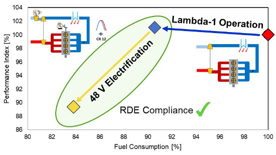
Figure 14, it is possible to appreciate that the performance worsening, caused by the adoption of the stoichiometric combustion on the entire engine map, was almost completely overridden (+1% PI) with the countermeasures investigated for the 1.4 L stoichiometric engine (increased turbine limit temperature and knock calibration update in the ST-Conv concept). The fuel consumption reduces by 2.6% on the WLTC and by 9.4% on the RTS-95 with respect to the reference case, while no difference is obtained in the NEDC. The 48 V electrification of the powertrain (ST-MHEV concept) leads to a significant improvement of the vehicle performance (PI reduction for the ST-MHEV up to 6.3% with respect the Base concept), while the fuel consumption benefits are about 4.6% on NEDC and WLTC and more than 6% on RTS-95 compared to the ST-Conv powertrain. Finally, the HE-MHEV concept, whose engine features an increased CR and exploits the potentiality of the eSC and of the Miller Cycle, dramatically reduces the turbolag effect due to the prompt supercharging response and is able to reduce the peak power gap of the engine taking advantage of the Miller cycle introduction. The result is an additional improvement of the PI by 4% with respect to the electrified concept ST-MHEV (achieving an impressive 10% of PI improvement compared to the reference Base vehicle); furthermore, the HE-MHEV concept is capable of reducing the fuel consumption by 1% compared to the ST-MHEV.
4. Conclusions
In this work the impact of RDE regulation on the development of Lambda-1 engine concepts and the 48 V electrification benefits in terms of fuel economy and vehicle performance for a gasoline passenger car were investigated through numerical simulation. Vehicle performance and fuel consumption were evaluated according to several transient maneuvers and three driving cycles, respectively. The reference engine (Base) was a turbocharged gasoline engine compliant with the Euro 5 emissions standards; three additional powertrains were developed in order to achieve the compliance with the RDE regulation. To do so, while in the meantime maintaining the engine performance at a comparable level with respect to the reference engine, some hardware and control modifications were investigated: the turbine inlet limit temperature was increased (+ 50 °C compared to Base engine); additionally, the knock calibration was refined targeting the engine operation at knock limited spark advance, resulting in a moderate advance of the combustion phasing in the high load region (ST-Conv). Afterwards, an increased compression ratio (from 9.8 to 12) was adopted in an electrified powertrain concept, together with a Miller cycle for knock mitigation and an electric supercharger.
Simulation results demonstrated that the stoichiometric engine concept integrated in a P0 48 V electrified powertrain (ST-MHEV) achieves a performance improvement up to 6% with respect to a conventional gasoline car in terms of vehicle acceleration. A significant reduction of the fuel consumption was achieved with the Lambda-1 electrified powertrain (7.3% on the WLTC and more than 15% on the RTS-95). The fuel economy benefits derived both from the increased engine efficiency and from the powersplit optimization performed by the energy management system; in particular, the hybrid control strategy aims to concentrate the engine operation in the maximum efficiency load region.
The possibility to exploit an electrified boosting system as the eSC (in the HE-MHEV powertrain) considerably improved the transient response of the engine, dramatically reducing the performance time in elasticity maneuvers (up to −11% on average). As far as the fuel consumption is concerned, the engine concept featuring the eSC coupled with other engine technologies like the Miller cycle and the increased CR, reduced the CO2 emission of the vehicle of about 1% averaging the results over the NEDC, WLTC and RTS-95.
An evolution of this work will be the integration of the eSC activation strategy in the EMS going beyond the conventional rule-based approach. This will require a modification of the ECMS so that the overall electric power needed by the vehicle would be considered in the powersplit operation. Moreover, this approach could be expanded to take into account additional auxiliaries power load as, for example, an electric catalyst (requiring the updating of the vehicle virtual test rig to include also cold start condition).


