Research on DFIG-ES System to Enhance the Fast-Frequency Response Capability of Wind Farms

The Key Laboratory of Smart Grid of Ministry of Education, Tianjin University, Tianjin 300072, China
*
Author to whom correspondence should be addressed.
Energies 2019, 12(18), 3581; https://0-doi-org.brum.beds.ac.uk/10.3390/en12183581
Submission received: 23 July 2019
/
Revised: 16 September 2019
/
Accepted: 18 September 2019
/
Published: 19 September 2019
(This article belongs to the Special Issue Wind Power Integration into Power Systems: Stability and Control Aspects)
Abstract
:With the increasing penetration of wind power generation, the frequency regulation burden on conventional synchronous generators has become heavier, as the rotor speed of doubly-fed induction generator (DFIG) is decoupled with the system frequency. As the frequency regulation capability of wind farms is an urgent appeal, the inertia control of DFIG has been studied by many researchers and the energy storage (ES) system has been installed in wind farms to respond to frequency deviation with doubly-fed induction generators (DFIGs). In view of the high allocation and maintenance cost of the ES system, the capacity allocation scheme of the ES system—especially for fast-frequency response—is proposed in this paper. The capacity allocation principle was to make the wind farm possess the same potential inertial energy as that of synchronous generators set with equal rated power. After the capacity of the ES system was defined, the coordinated control strategy of the DFIG-ES system with consideration of wind speed was proposed in order to improve the frequency nadir during fast-frequency response. The overall power reference of the DFIG-ES system was calculated on the basis of the frequency response characteristic of synchronous generators. In particular, once the power reference of DFIG was determined, a novel virtual inertia control method of DFIG was put forward to release rotational kinetic energy and produce power surge by means of continuously modifying the proportional coefficient of maximum power point tracking (MPPT) control. During the deceleration period, the power reference smoothly decreased with the rotor speed until it reached the MPPT curve, wherein the rotor speed could rapidly recover by virtue of wind power so that the secondary frequency drop could be avoided. Afterwards, a fuzzy logic controller (FLC) was designed to distribute output power between the DFIG and ES system according to the rotor speed of DFIG and of ES; thus the scheme enabled the DFIG-ES system to respond to frequency deviation in most cases while preventing the secondary frequency drop and prolonging the service life of the DFIG-ES system. Finally, the test results, which were based on the simulation system on MATLAB/Simulink software, verified the effectiveness of the proposed control strategy by comparison with other control methods and verified the rationality of the designed fuzzy logic controller and proposed capacity allocation scheme of the ES system.
1. Introduction
With the rising emerging energy crisis and environmental problems, governments around the world are actively investing in the utilization and development of new renewable energy [1]. Wind energy and solar energy, as reliable renewable energy sources, have been exploited rapidly in recent years. However, wind power generation is challenging the safety and stability of the power system, as it results in the increasing penetration of wind power generation into the power grid.
In recent years, wind farms have been required to have frequency regulation capability [2]. The frequency regulation participated in by wind farms commonly involves two aspects: fast-frequency response and primary frequency regulation [3]. The fast-frequency response, which is also called short-term frequency response, is the intrinsically inertial response from synchronous generators to suppress the frequency fluctuation and raise the frequency nadir by means of releasing a large amount of kinetic energy stored in the rotating masses. The fast-frequency response lasts until the frequency drop to the nadir or rise to the peak. The primary frequency regulation is the process where the output active power of generators is adjusted to strike a power balance between generation side and load side so that the frequency is restored within the safe range. Considering the great demand of support power and long duration of the primary frequency regulation, the participation of wind farms in primary frequency regulation means the wind turbines have to operate in the load reduction mode before the frequency fluctuation so as to be able to provide enough reserve active power, which, however, reduces the profit of wind farms because of the waste of wind resources [4]. In spite of the increasing proportion of wind power generation in electricity generation, the primary frequency regulation is still the main task of conventional synchronous generators in view of the fluctuation of wind power output caused by the fluctuation of wind speed [5]. Therefore, the research on wind farms to enhance fast-frequency response capability is more important for the current grid structure.
At present, doubly-fed induction generators (DFIGs) are commonly applied in wind farms. Nevertheless, the rotor speed and the system frequency are decoupled because of the existence of the electronic converter [6], which means that the rotational kinetic energy of the rotor is completely “hidden”. The contribution of DFIG to the frequency regulation is almost none, so the frequency stability will be jeopardized with the increasing proportion of wind power generation and the decrease of inertia of the entire system [7]. Consequently, international scholars have put forward a series of schemes to deal with this problem.
Compared with conventional synchronous generators, DFIGs have greater inertial energy due to their wider range of speed regulation. Reference [8] added an accessional differential control into the maximum power point tracking (MPPT) control link in order to lift instant output power by releasing the stored rotational kinetic energy of the rotor once the frequency drop event occurred. The power reference was modified as the frequency deviation was set as input variable in the MPPT control link. Although this scheme enables DFIG to utilize its inertial energy to realize fast-frequency response, DFIG would absorb much energy from the grid to recover its rotor speed, which would lead to the secondary frequency drop. Reference [9] proposed a scheme in which the instant output power of DFIG was maintained at the maximum level before the rotor speed exceeded the safe range once the frequency drop event was detected. Then, the power reference was decreased dramatically so that the rotor speed was able to recover. This scheme enables DFIG to support the frequency with its best effort and prevent over-deceleration of rotor speed in theory. However, because of the slow response of rotor speed control, in practice, the secondary frequency drop still happens when the rotor speed regulation range is too large, as is shown in the simulation results. Taking rotor speed and wind power penetration level into account, reference [10] made DFIG maintain the incremental power for a preset period and forced the rotor speed converge to a stable operating range with power reference decreasing. Because the incremental power varies with the penetration level according to the calculation process of the power reference, DFIG is unable to provide sufficient power to support frequency when the power system has low wind penetration, which should be easier to deal with for wind farms. Furthermore, DFIG is unable to conduct fast-frequency response under the condition of extreme wind speed (too high or too low), as DFIG does not possess surplus inertial energy under extremely low wind speed and cannot increase the output power under extremely high wind speed. Thus, wind farms have difficulties relying on DFIGs alone to respond to system frequency.
The energy storage (ES) system has been widely applied in electrical fields to suppress the fluctuation of output power and regulate frequency because of its stable performance, flexible control, and fast response [10]. Thus, it is suitable for the fast-frequency response in wind farms. In reference [11], in order to avoid the frequency secondary drop caused by rotor speed recovery, the ES was integrated at the AC bus of wind farm to respond to frequency fluctuation with DFIG where DFIG was the main part and ES was the auxiliary part. ES simply provided the energy required in the period of rotor speed recovery or supplemented the insufficient energy supplied by DFIG, so the enormous potential of ES was not made full use of in this scheme. To make the best use of both the capability of ES and the wind resources, reference [12] made only ES take charge of the fast-frequency response, whereas DFIG operated in the MPPT mode without responding to frequency fluctuation. However, there is no doubt that the service life of ES would reduce and the maintenance cost of ES would increase in this scheme. In addition, the capacity of the ES system was given as 10% of the DFIGs’ rated power without any mathematical deduction. Herein, whether this scheme could increase the profit of wind farms or not is questionable. In reference [13], a hybrid control strategy is proposed, considering the de-loading (DL) state of wind turbine generator (WTG) and the state of charge () of ES. However, the power reference of the DFIG-ES system for fast-frequency response is calculated on the premise of the power load deviation forecast, which is hard to acquire precisely in practice. Reference [14] integrated an ES system at the DC bus of a DFIG to share the frequency regulation burden, and proposed coordinated control strategy to improve the nadir with consideration of the of ES and the operating state of DFIG. Nevertheless, the DFIG-ES system is unable to provide extra active power and participate in frequency regulation under extremely high wind speed because of the capacity limitation of the converter in DFIG. Moreover, this scheme increases the number of ES systems and creates unnecessary maintenance and management cost when the ES system is embedded at the DC bus of DFIG. In summary, the research works mentioned above did not involve an effective coordinated control method for DFIG and ES to respond to frequency disturbance with their most effort under any wind speed.
To enhance the fast-frequency response capability of wind farms, this paper puts forward a coordinated control scheme of the DFIG-ES system with the consideration of different wind speed. The overall power reference of the DFIG-ES system was calculated on the basis of the frequency response characteristic of synchronous generators. Therefore, according to the biggest inertial energy that synchronous generators can provide, a capacity allocation scheme of ES for the fast-frequency response was proposed, and the capacity allocation principle was to make the wind farm possess the same potential inertial energy as that of synchronous generators set with equal rated power. The capacity allocation of ES is meaningful because it reduces the allocation and maintenance cost of ES compared with other schemes. In order to enable DFIG to respond to frequency deviation with ES, once the power reference of DFIG was determined, a novel virtual inertia control method was put forward to release rotational kinetic energy and produce power surge by means of continuously modifying the proportional coefficient of maximum power point tracking (MPPT) control. During the deceleration period, the power reference smoothly decreased with the rotor speed until it reached the MPPT curve, then the rotor speed could rapidly recover by virtue of wind power, so that secondary frequency drop could be avoided. After the deficiencies of DFIG and ES solely accomplishing fast-frequency response were respectively analyzed, a fuzzy logic controller was designed to distribute the output power between DFIG and ES according to the rotor speed of DFIG and of ES, which ensured the effective cooperation between DFIG and ES. In the end, the test results, which were based on the simulation system on MATLAB/Simulink software, verified the effectiveness of the proposed control scheme by comparison with other control methods and verified the rationality of the designed fuzzy logic controller and proposed capacity allocation scheme of the ES system.
2. Modeling of the DFIG-ES System
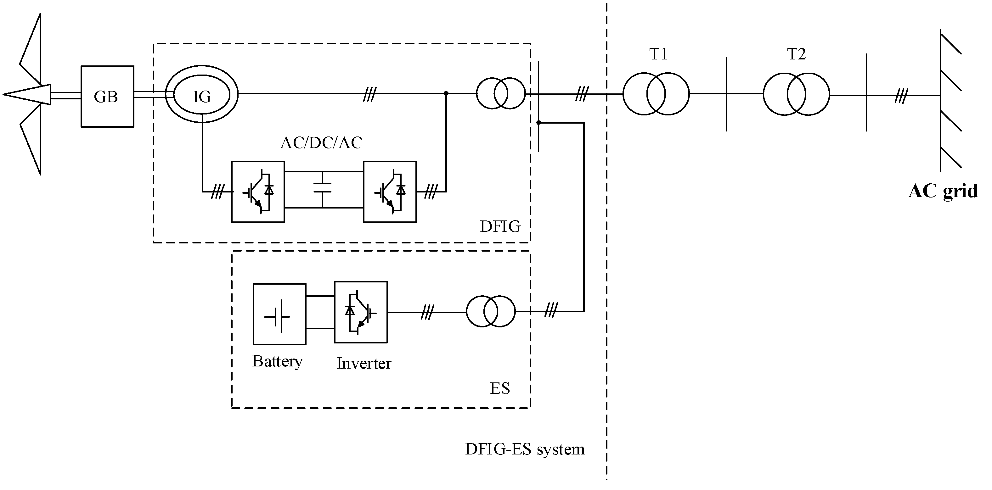
The model structure of the DFIG-ES system introduced in this paper is shown as Figure 1.
2.1. Doubly-Fed Induction Generator Model
In the dq two-phase synchronous rotating coordinate system, the voltage, flux, power, and electromagnetic torque equations of the doubly-fed induction generator are shown as follows [15,16]:
where , , are stator and rotor flux on the d and q axes, respectively; are equivalent self-inductance and mutual inductance of the stator and rotor; ,, are stator and rotor current on the d and q axes; ,, are the stator and rotor voltage on the d and q axes; is electromagnetic torque; represents pole pairs of DFIG; is synchronized angular velocity; represents rotor angular velocity; is the active power of DFIG; and is the reactive power of DFIG. Ignoring the change of stator resistance and stator flux, the d axis of the synchronous rotating coordinate system is oriented according to the space vector of grid voltage. The relationship between stator-side power and rotor current is shown as follows:
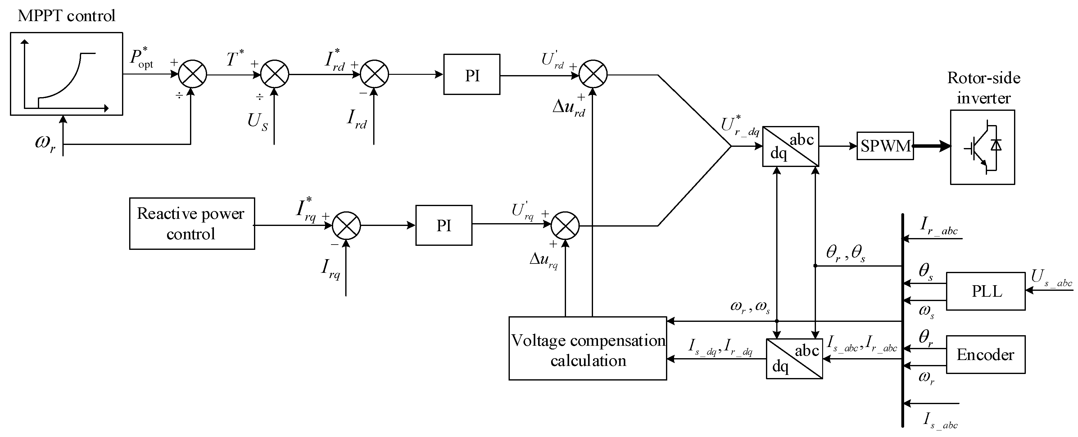
Once the stator voltage vector control is adopted, the active power of DFIG is controlled by the rotor current on the d axis, and the reactive power is controlled by the rotor current on the q axis. Thus, the active power and reactive power of DFIG are decoupled. The control diagram of the rotor-side converter is shown in the Figure 2 [8]. This control link contains double loops. The outer loop is a power loop, and the inner loop is a current loop. The rotor current reference, and , in the current loop are respectively determined by the maximum power point tracking control and the reactive power control in the outer loop. In the maximum power point tracking control, the relationship between active power reference value and rotor angular velocity is as follows:
where is the proportional coefficient of the maximum power point tracking control; represents the lowest rotor angular velocity of DFIG; is the rated rotor angular velocity of DFIG; is the maximum rotor angular velocity; and is the maximum active power output of DFIG.
2.2. Energy Storage System Model
Different types of batteries can be chosen to make up an energy storage system, such as nickel-cadmium batteries, sulfur-sodium batteries, and lithium-ion batteries, among others. Among them, the energy storage technology of the lithium-ion batteries has developed rapidly over the years [17]. Thus, lithium-ion batteries are integrated into the ES system in this paper.
The ES affiliated to DFIG is controlled by an independent inverter, which features a fast response performance on the frequency regulation. Considering that the capacity of the ES is finite, the of ES should be taken into consideration [18], which is calculated by
where is the state of charge at time ; is the initial state of charge; is the output power (positive when ES is discharging) of ES at time ; is the operation time of ES; and is the rated capacity of ES.
Considering that the capacity of ES is a main factor influencing the frequency regulating capability of wind farms, especially in the case where DFIG is unable to respond to frequency deviation under extreme wind speed, a capacity allocation scheme of ES will be discussed later in the paper.
3. Capacity Allocation Scheme of ES
In reference to power system analysis, inertia time constant H is defined as the ratio of rotor inertial energy to rated capacity of generator at synchronous angular velocity [19]. Since the inertial energy of DFIG is not available naturally during a frequency fluctuation and the amount of virtual inertial energy provided by DFIG depends on the parameters in virtual inertial control link (discussed in the next section), the potential inertia time constant of power systems containing wind farms and conventional power plants can be represented by
where n, m, l is the number of synchronous generators of DFIG and ES systems, respectively; is the pole pairs of synchronous generator ; represents the rotational inertia of synchronous generator ; is the rotational kinetic energy of DFIG ; is the storage energy of ES ; and is the total rated capacity of the generators in power system.
The DFIG operating in the MPPT mode, unlike the synchronous generator whose rotor speed is coupled with the system frequency, cannot exchange power with the grid when the system frequency fluctuates. Therefore, large-scale wind farms connected to the grid will inevitably lead to the reduction of system inertia, and the allocated capacity of ES will directly affect the inertia of the wind farm and even the whole power system. However, in view of the relatively high configuration and maintenance cost of ES, the larger the capacity of ES means the higher construction and maintenance cost of wind farms. Considering that synchronous generators contribute with the most electricity generation, adjusting the output energy of the wind farm to be approximately same as the inertial energy produced by conventional synchronous generators would reduce the negative impact of large-scale wind farms on frequency stability of the power system and be convenient for grid staff to dispatch the power grid [20]. Therefore, the capacity allocation scheme of ES installed in wind farms for fast-frequency response is proposed. The capacity allocation principle is to make the wind farm have the same potential inertial energy as that of synchronous generators set with equal rated power.
According to the power grid operating regulations in China [21], the rotor angular velocity of the synchronous generator is usually limited between 0.95 and 1 during frequency regulation. The maximum rotational kinetic energy released from the synchronous generator is
The rotational kinetic energy of the synchronous generator at rated angular velocity is
where is the inertia time constant of the synchronous generator; is the rated output active power of the synchronous generator; can be regarded as the maximum inertial energy produced by the synchronous generator during fast-frequency response; The time during the frequency dropping from normal to the nadir is , and therein the virtual inertial energy released by ES is
where is the average output power of ES during the fast-frequency response; and represents the time duration of the fast-frequency response. Then, can also be expressed as
Generally, the inertia time constant of the synchronous generator is about 4 to 18 s, and the fast-frequency response lasts about 7 to 15 s [22]. Thus, we set as 11 s and as 11 s (average value), giving
Considering the huge instantaneous throughput of the ES system [23], the time required for the output power to reach the specified value, compared with the time duration of the fast-frequency response, can be negligible. In view of a certain output power fluctuation margin, the maximum output power of the ES is set as 5% of the rated power of the wind farm.
Deep charging and discharging will seriously reduce the service life of the ES system [24]. In this paper, the charging and discharging range of ES is maintained between 10% and 90% of the rated capacity. Normally, the initial of the ES system is 50%, so the available storage energy used for fast-frequency response equals 40% of the rated capacity. As the time duration of fast-frequency response is supposed as 11 s, referring to Equation (10), the rated capacity of the ES is calculated as follows:
Therefore, the rated capacity of the ES system affiliated to DFIGs equaled to 0.764% of the rated power of the wind farm.
4. Coordinated Control Strategy of DFIG-ES System with Consideration of Wind Speed
4.1. Division of Wind Speed Region
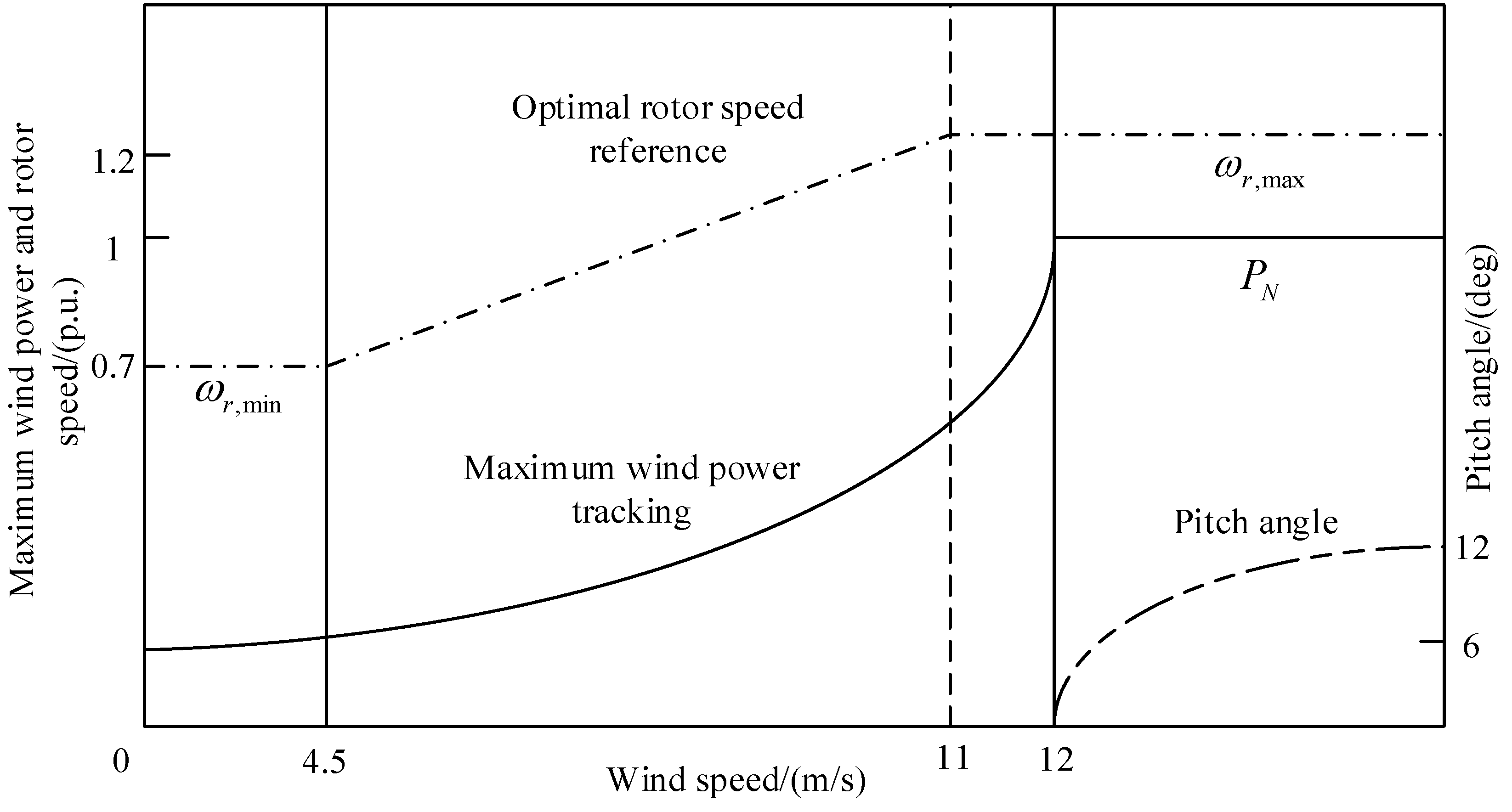
When DFIG is in normal operation, converter control and pitch control are comprehensively applied to adjust the operation state of wind turbine [10,25,26]. In the case of low wind speed, the control purpose is to make the operating point follow the maximum power point tracking curve and capture the maximum wind energy. With the increment of wind speed, the rotor speed reaches the limit and maintains at the maximum. In the case of high wind speed, the wind energy capturing efficiency is reduced by adjusting pitch angle so that the output power of DFIG is maintained at the maximum (rated power) [27]. The relationship among rotor speed, active power, pitch angle and wind speed is shown in Figure 3.
Because the operation state of DFIG is closely related to the wind speed, the wind speed was divided into three regions before the control strategy was discussed in this paper:
- (1)
- Low speed region ( < 6 m/s)—the rotor speed just maintains at , so the DFIG cannot respond to the frequency drop by releasing the rotational kinetic energy.
- (2)
- Middle speed region (6 m/s ≤ ≤ 12 m/s)—the DFIG operates in MTTP mode to maximize the efficiency of capturing wind energy. The fast-frequency response can be achieved by releasing the rotational kinetic energy, except for the scenario where the output power is close to the maximum.
- (3)
- High speed region (12 m/s < )—although the rotational kinetic energy is huge, the output power of the DFIG is limited by the capacity of the converter and no excess energy can be generated, so the DFIG cannot undertake the task of fast-frequency response.
It can be seen that when the wind speed belongs to the low or high speed region, the DFIG cannot provide inertial energy and only relies on ES to complete fast-frequency response. Next, we will discuss the coordinated control strategy of the DFIG-ES system when the wind speed belongs to the middle speed region. It was noted that the control objective is very easy to achieve when frequency suddenly rises because DFIG can operate in load reduction mode and ES can operate in charging mode. Thus, in this paper, we only discuss frequency drop incident.
4.2. Virtual Inertia Control of DFIG-ES System
During the period of fast-frequency response, in order to make the wind farm emit the same amount of inertial energy as the synchronous generators set with equal rated power, the energy emitted by the DFIG-ES system can be represented as
where is the energy emitted by DFIG; is the energy emitted by ES; is the inertia constant of DFIG; represents the virtual inertia constant of the DFIG-ES system; is the change of synchronized angular speed; is the rotor speed change of DFIG; and is the initial rotor angular velocity of DFIG.
Supposing that the energy emitted by DFIG accounts for (0 ≤ ≤ 1) of the total energy emitted by the DFIG-ES system, the equivalent virtual inertia constant of the DFIG can be represented as
where is the rotor speed regulation coefficient, and is the equivalent virtual inertia constant of DFIG.
According to Equation (13), it can be seen that the equivalent virtual inertia constant of the DFIG is determined by not only the inertia constant of the DFIG, but also the initial angular velocity , the rotor speed regulation coefficient , and the output power proportion of DFIG .
On the basis of Equation (3) and Figure 2, in order to complete the fast-frequency response by releasing the kinetic energy, we can modify the proportional coefficient to adjust the operation state of DFIG. Supposing the frequency change is , the proportional coefficient is modified to during the frequency regulation period, with the rotor angular velocity decreasing to to release rotational kinetic energy. The decrease range of rotor speed should not be too large (by limiting output power proportion of DFIG and active power reference) so as to ensure that the rotor will not absorb too much energy from the grid during the rotor speed recovery period. According to the maximum power point tracking curves under different wind speeds, if the rotor speed regulation is within the safe range, the secondary frequency drop would be avoided. Referring to Equations (13) and (3), supposing the range of rotor speed regulation is not too large, then we can find
where is the modified rotor speed regulation coefficient with consideration of output power proportion . Thus, the modified proportional coefficient can be represented as
which follows the restrictions
Therefore, if we input the frequency change into the MPPT control link of DFIG, then the fast-frequency response and rotor speed recovery can be realized by modifying the proportional coefficient according to Equation (15). In particular, when the fast-frequency response is over, as the primary frequency regulation continues and the frequency deviation fades, the proportional coefficient changes smoothly to the original value and the operating point moves smoothly back to the original place. In the light of relatively long duration of primary frequency regulation, the energy required for rotor speed recovery depends mainly on the wind energy (supposing the wind speed remains), and secondly on the huge ramp rate of synchronous generators set. Therefore, as long as the speed regulation range is not particularly large, the active power shortage caused by the rotor speed recovery can be almost negligible.
The fast-frequency response progress of DFIG is shown in Figure 4. The DFIG originally operates at point A on the MPPT curve, assuming that the wind speed remains at 9 m/s throughout the period. When the frequency drop event is detected, the power reference is surged immediately and the operating point of DFIG moves rapidly to point P. Because the electromagnetic power of DFIG is larger than the mechanical power, the speed decreases rapidly. At the same time, the output power decreases until the operating point reaches the MPPT curve at point B, where the electromagnetic power is equal to the mechanical power. As is shown in Figure 4, the power shortage caused by rotor speed regulation is very small, and thus Equation (14) is reasonable. The frequency deviation decreases gradually as the primary frequency regulation processes, so the operating point moves smoothly from B to A. It is noteworthy that the energy required in rotor speed recovery period is mainly from the wind energy. Therefore, the secondary frequency drop can be avoided in this scheme, which will be proved in the study case.
According to the Equations (7) and (12), the energy emitted by ES, which accounts for (0 ≤ ( ≤ 1) of the output energy, can be expressed as
Considering that the output power released by ES is basically stable, the output power of ES can be expressed as
4.3. Determination of Output Power Proportion
Both DFIG and ES have to be taken into account to determine the output power proportion . For DFIG, if its output power proportion is too large, it may face the risk of torsional vibration in the shaft system caused by too much rotor speed regulation [28], the risk of an unstable power grid caused by a rotor speed recovery range that is too large, and the risk of DFIG disconnection due to rotor speed declining below the threshold [29]. For ES, if its output power proportion is too large, it may face the risk of service life reduction as the result of frequent deep charging or discharging, which will cause excess maintenance cost. Therefore, the determination of output power proportion is a complicated problem where the appropriate mathematical expressions are difficult to establish.
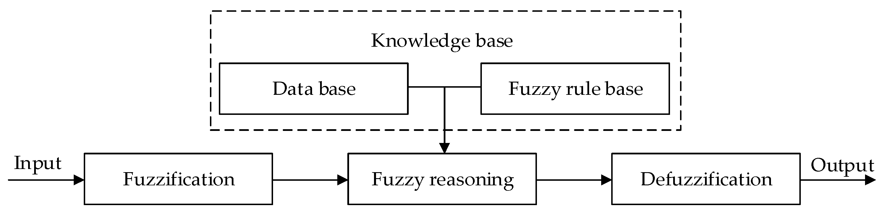
The fuzzy logic control method shows its functionality when the control process cannot be described by a concrete mathematical model [29,30,31]. The principle diagram of the fuzzy logic control is shown in Figure 5.
Then the fuzzy logic controller (FLC) to determine the output power proportion can be designed as follows:
- (1)
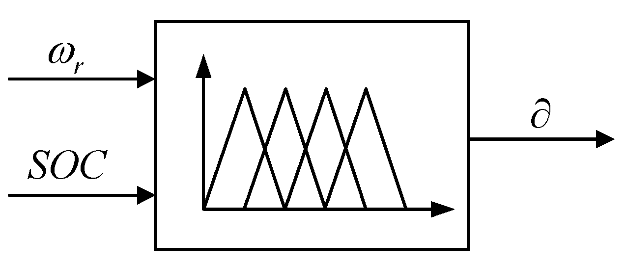
- The structure of fuzzy logic controller: The rotor speed of DFIG and of ES are selected as input variables of FLC, and the output power proportion of DFIG is selected as the output variable of FLC. The corresponding FLC structure is shown in Figure 6.
- (2)
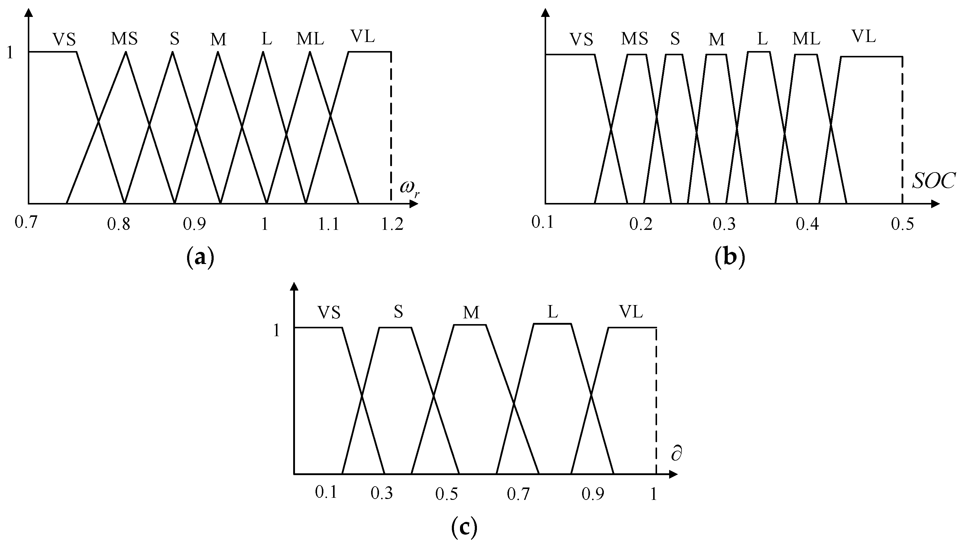
- The fuzzy state and the shape of membership function of fuzzy subset: Determining the fuzzy state means determining the quantity of linguistic values of variables. If the quantity of linguistic values is large then the control rules are precise, which will lead to the complexity of the controller. If the quantity of linguistic values is small then the control rules are easy to implement, but too few linguistic values will result in a coarse controller [32]. Therefore, both simplicity and precision should be considered. Seven fuzzy domains for input variables are set: VS (very small), MS (middle small), S (small), M (middle), L (large), ML (middle large), VL (very large). Five fuzzy domains for output variable are set: VS (very small), S (small), M (middle), L (large), VL (very large). The common shapes of membership function are triangle and trapezoid. Compared with the and , the rotor speed is a more precise variable with clearer discrimination, so a triangle is chosen as the shape of the membership function of the rotor speed . The domain of is [0.7, 1.2] p.u. The trapezoidal is chosen as the shape of membership function of . The domain of is [0.1, 0.5] p.u. When > 0.5 p.u, the value of is set as 0.5 p.u. The trapezoidal is chosen as the shape of membership function of . The domain of is [0, 1] p.u. The membership functions used in FLC are shown in Figure 7.
- (3)
- The fuzzy rules: The rules of the fuzzy logic controller are determined according to the engineering experience accumulated by the engineering experts during their long-term work [29]. The fuzzy rules designed in this paper are mainly based on the following engineering experience:
- If the rotor speed of the DFIG is too low or too high, the DFIG cannot release excess energy by reducing the rotor speed. If the of the ES is at a high level, the fast-frequency response is completed by the ES alone.
- If the of the ES is lower than 10%, the ES cannot emit energy to respond to frequency drop. If the rotor speed of the DFIG is relatively high, the fast-frequency response is completed by the DFIG alone.
- If the rotor speed of the DFIG is relatively high and the of the ES is higher than 10%, the frequency response is completed by DFIG and ES altogether, and the appropriate output power proportion of each device is determined according to their stored virtual inertial energy.
The fuzzy logic control rules are shown in Table 1. - (4)
- Defuzzification: Maximum of mean method, maximum average method, and center of gravity method are commonly used for defuzzification [29]. Considering the error mined by the center of gravity method is the least among these methods, the center of gravity method is applied for defuzzification. The equation is as follows:where is the value of output power proportion; is the non-fuzzy value of output power proportion; (a, b) is the range of ; and uc(∂eout) is the membership function of .
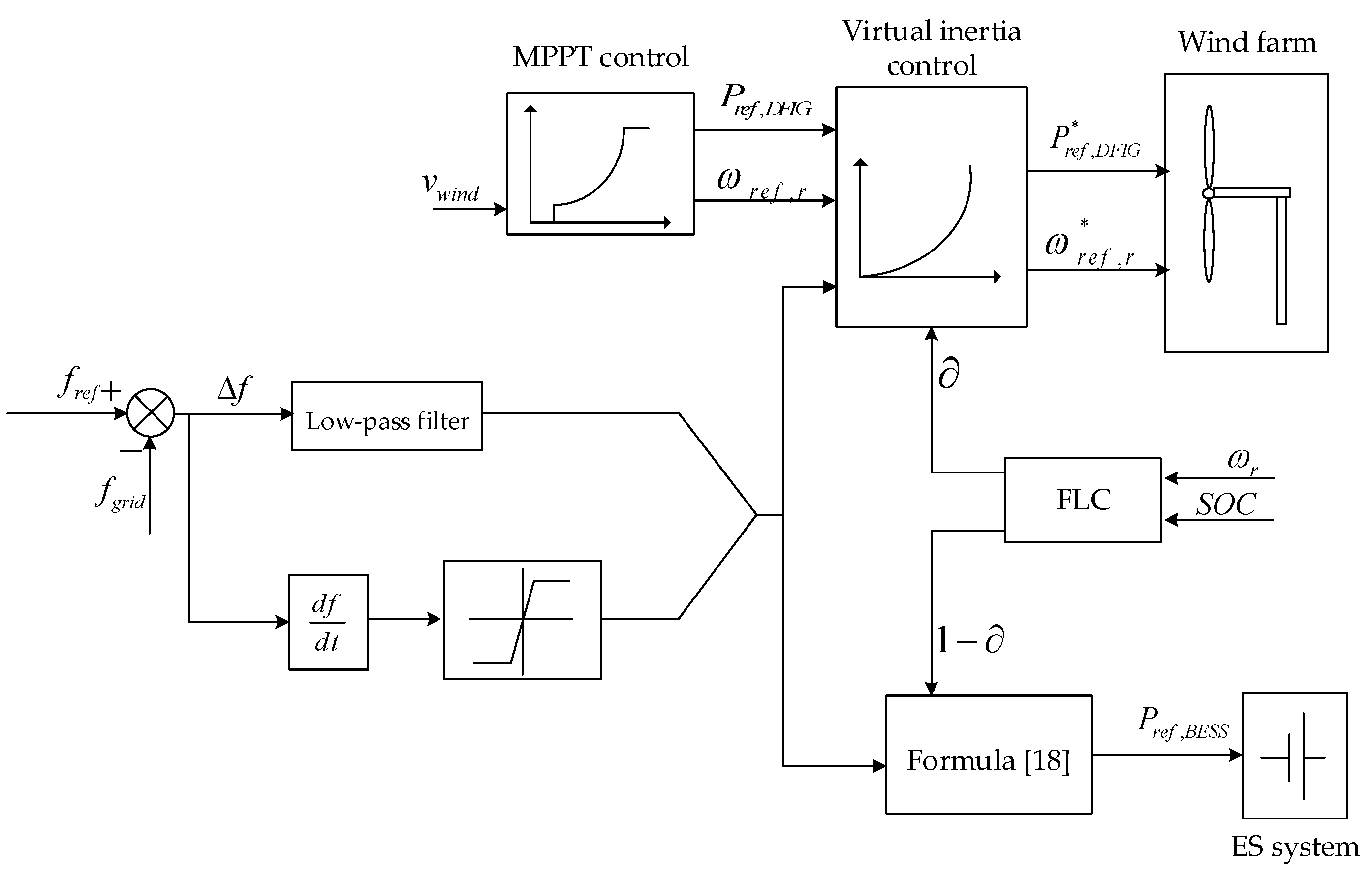
The coordinated control strategy of the DFIG-ES system for fast-frequency response is shown in Figure 8 (if the wind belongs to the high or low speed regions, the is set as 0).
5. Case Study
5.1. Introduction to the Simulation System
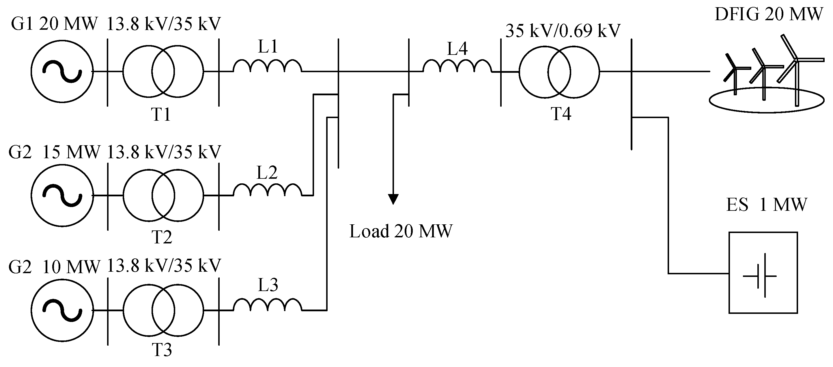
In order to verify the effectiveness of the proposed control strategy and the rationality of the designed fuzzy logic controller and proposed capacity allocation scheme of the ES system, a simulation system, whose structure is shown in Figure 9, was built on MATLAB/Simulink software. Because the proposed control strategy referring to single DFIG and single ES is universal, an equivalent DFIG was selected to represent the wind farm. The simulation system consisted of an ES system following the capacity allocation scheme, as well as three synchronous generators representing three power plants, transformers, loads, and equivalent lines. The battery ES model used in this paper was from MATLAB/Simulink original library, and this model was an integration of serial and parallel combinations of multiple single cells. The detailed parameters of each component in the simulation system were obtained from [12,33] and are shown in Table 2.
As mentioned above, for the frequency rise event, the frequency response can be easily achieved by increasing the rotor speed or adjusting the pitch angle to reduce the active output of the wind farm. Moreover, the reduction of output power of two devices and power proportion between two devices can also be used in reference to the control strategy proposed in this paper. Therefore, simulation tests involved only the frequency drop incident. The simulation scenario was that the load power increased by 20 MW at 5 s.
5.2. Simulation Result
The coordinated control strategy of DFIG-ES, the inertia control of only DFIG [8], and no inertia control were simulated. The simulation results of these three schemes were compared to verify the effectiveness of the proposed method and its superiority over the traditional inertia control method of DFIG. Considering that the DFIG-ES system operating under low or high wind speed only relies on ES to achieve a fast-frequency response, this paper chose middle and high wind speed as simulation scenarios. Furthermore, in order to verify the rationality of the fuzzy logic controller proposed in this paper, the scenarios where the DFIG-ES system with different under middle wind speed were simulated.
5.2.1. Simulation Result under Middle Wind Speed
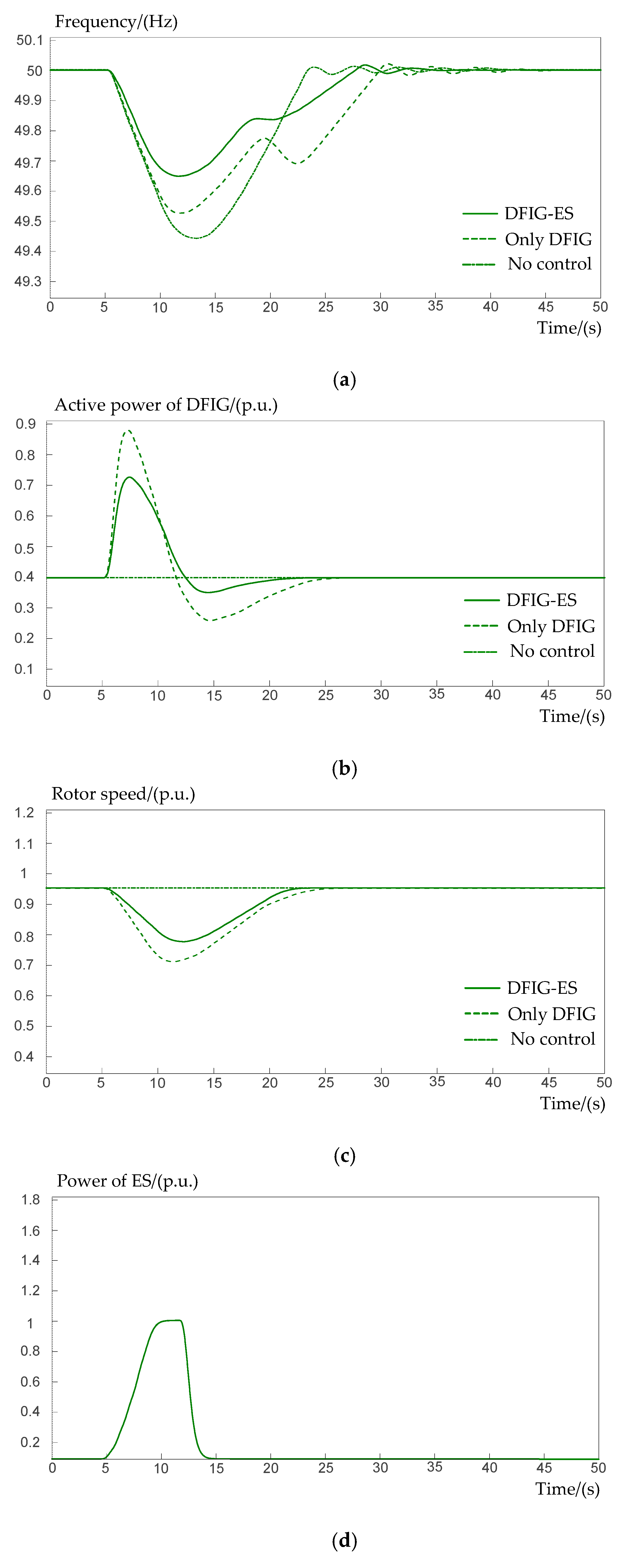
In the simulation, the wind speed was set as 9 m/s and the initial of ES was set as 50%. The simulation result under middle wind speed is shown in Figure 10. Figure 10a shows the system frequency curve. The output active power of DFIG and rotor speed curves are shown in Figure 10b,c. The output active power of ES is shown in Figure 10d.
5.2.2. Simulation Result under High Wind Speed
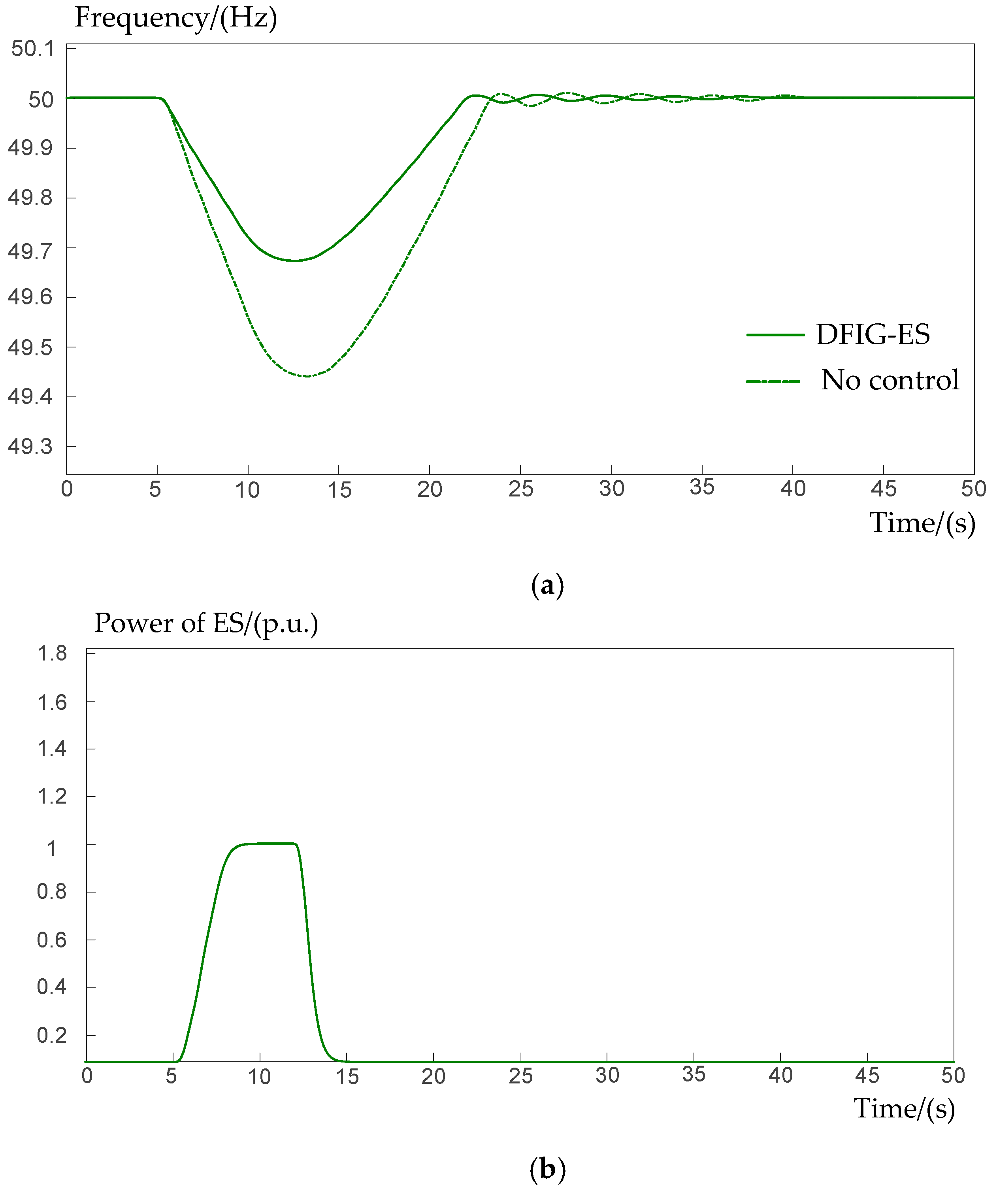
Under the conventional inertia control method, the output active power of DFIG reached the maximum power in this scenario, and thus the frequency response effect under inertia control was the same as that under no inertia control. Therefore, in this part, the coordinated control method and no control method were taken as comparison. The wind speed was set as 13 m/s and the initial of ES was set as 50%. The frequency curves are shown in Figure 11. Figure 11a shows the system frequency curve. The output active power of the ES is shown in Figure 11b.
5.2.3. Simulation Result under Different
5.2.4. Simulation Result When Is below 10%
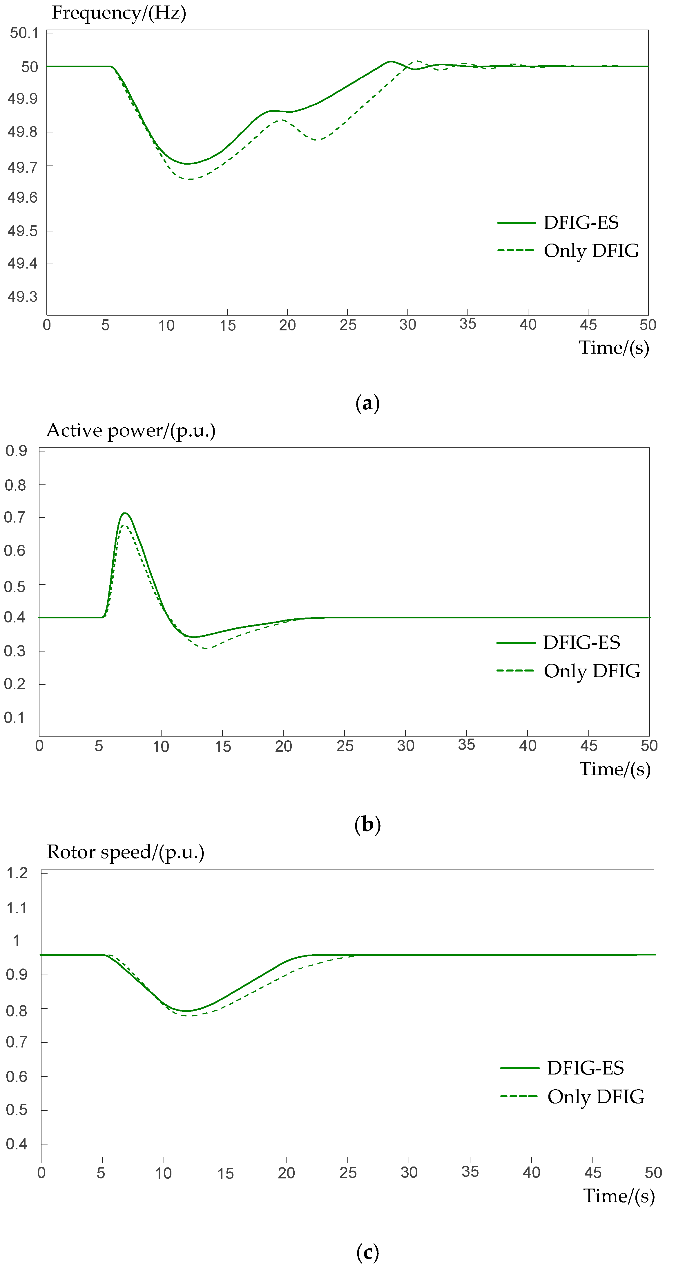
When the wind speed was 9 m/s and was below 10% (wherein the ES system cannot work), in the simulation scenario the load power increased by 10 MW at 5 s. The frequency curves are shown in Figure 13a. The output active power curves of DFIG and the rotor speed curves are respectively shown in Figure 13b,c.
6. Discussion
Under middle wind speed, the cooperative frequency support of DFIG and ES was the objective of the proposed control strategy. The nadir of frequency under the coordinated control method was 49.65 Hz, which was higher than the other two nadirs. This means the coordinated control method effectively decreased the frequency drop range and was conducive to maintaining the frequency stability of the power grid. In Figure 10a, the frequency curve under the conventional inertia control of DFIG incurred a second drop due to the large active power shortage caused by rotor recovery, which jeopardized the safety of the power grid. Because the output active power of DFIG was determined by Equation (15) and the fuzzy logic controller, it decreased with the decline of rotor speed until the fast-frequency response finished. It can be seen that the regulation range of rotor speed under the coordinated control method was the smallest because the frequency regulation was also supported by ES. The DFIG operated only in MPPT mode when no inertia control was taken, so it could not respond to frequency fluctuation. The output power of the ES, determined by Equation (18), climbed to the peak gradually and dropped fast once the fast-frequency response finished. Compared with frequency regulation effects of the other two methods, the coordinated control method not only completed the fast-frequency response, but also raised the nadir of frequency and alleviated the frequency fluctuation without causing a secondary frequency drop.
Under high wind speed, DFIG cannot respond to the frequency fluctuation, but can rely on the ES to complete the fast-frequency response. The frequency nadir under the coordinated control method was 49.68 Hz, which was obviously higher than the nadir under the no control method. Because of the huge throughput and stable output of the ES, the nadir under the high wind speed was slightly higher than that under the middle wind speed. Furthermore, frequency deviation during the primary frequency regulation was alleviated because of the lack of the rotor speed recovery. The active power output of the ES shown in Figure 11b was similar to that in Figure 10d, while the output power stayed on the peak for longer duration. The simulation example validated that the wind farm operating under high wind speed relied on the ES with proposed capacity to complete the fast-frequency response. The frequency fluctuation was effectively restrained and the frequency nadir was improved by ES, which made up for the inability to participate in the frequency response of the DFIG.
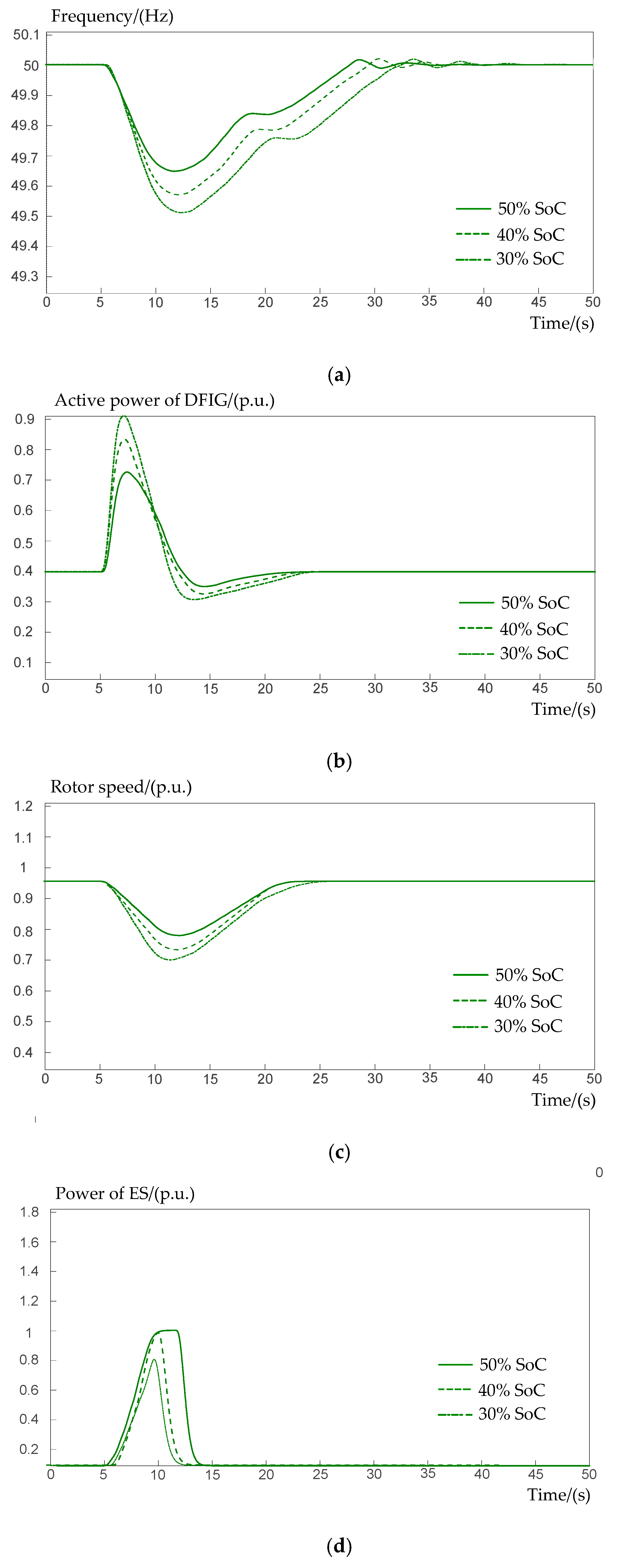
Under different , the wind speed was set as 9 m/s, and thus the initial rotor speed was fixed. The inertial energy possessed by the DFIG-ES system increased with the increment of initial . Therefore, the frequency nadir was 49.65 Hz, higher than the other two, when the was 50%. The output power proportion between DFIG and ES was determined by fuzzy logic controller. According to the fuzzy rules, once the initial rotor speed is fixed, the output power proportion of DFIG decreases with the increment of . It can be seen that the range of rotor speed regulation of DFIG was the smallest, the frequency oscillation during rotor speed recovery process was the smallest, and the overall output energy of DFIG was the smallest when the of ES was 50%. This means that the higher the , the more priority was given to reducing the mechanical loss of the DFIG; the lower the , the more priority was given to prolonging the service life of the ES. This simulation verifies that the fuzzy logic controller effectively determined the output power proportion between DFIG and ES under the middle wind speed. The maintenance cost of both DFIG and ES was comprehensively reduced under the premise of meeting the demand of fast-frequency regulation.
When the was below 10%, the ES system could not assist the DFIG to support frequency regulation. Thus, the DFIG only relied on itself to complete the fast-frequency response through virtual inertia control. Seemingly, the output active power of the DFIG-ES system showed the faster response and smaller power shortage. Therefore, the frequency nadir was improved to 49.71 Hz and the rotor speed gained a quick recovery under the proposed control method. However, when the frequency nadir was 49.64 Hz, a small secondary frequency drop incurred under the conventional inertia control method. This simulation result proves the excellent performance of DFIG in cases where the ES is unable to work, and verifies the superiority of the proposed virtual inertia control over the conventional inertia control.
7. Conclusions
In this paper, a novel coordinated control strategy was presented for the DFIG-ES system to enhance the fast-frequency response capability of wind farms.
The overall power reference of the DFIG-ES system was calculated on the basis of the frequency response characteristic of synchronous generators. On basis of this, the capacity allocation scheme of the ES system was presented and its principle was to make the wind farm possess the same potential inertial energy as that of synchronous generators set with equal rated power. The simulation results demonstrate that this scheme ensures the ES system is economical but possesses enough reserved energy to complete a fast-frequency response in most cases. Meanwhile, the scheme saves allocation and maintenance costs to some extent, compared with previous ES capacity allocation schemes.
A virtual inertia control of the DFIG-ES system was proposed to produce active power surge to improve the frequency nadir, and a fuzzy logic controller was designed to distribute the active power between DFIG and ES. In particular, the proposed virtual inertia control of DFIG ensured the rotor speed recovery without causing secondary frequency drop. To demonstrate the effectiveness of the proposed control scheme, a test system containing synchronous generators and a DFIG-ES system was built on MATLAB/Simulink software. The simulation results indicated the proposed control strategy made full use of the potential of both DFIG and ES to enhance the fast-frequency response capability of wind farms. The DFIG and ES could cooperate dynamically for fast-frequency response and improve the stability of the power grid and avoid the secondary frequency drop accident. Compared with conventional inertia control of only DFIG, the proposed control strategy is more reliable and adaptable.
Author Contributions
Conceptualization, S.T.; methodology, S.T.; software, S.T., X.J.; validation, S.T., X.J.; formal analysis, S.T.; investigation, S.T.; resources, S.T., X.J.; data curation, S.T.; writing—original draft preparation, S.T.; writing—review and editing, S.T., B.Z.; visualization, S.T.; supervision, B.Z.; project administration, B.Z.; funding acquisition, B.Z.
Funding
This research was funded by the National Natural Science Foundation of China, grant number 51477114.
Conflicts of Interest
The authors declare no conflict of interest.
References
- Lu, M.S.; Chang, C.L.; Lee, W.J.; Wang, L. Combining the Wind Power Generation System with Energy Storage Equipment. IEEE Trans. Ind. Appl. 2009, 45, 2109–2115. [Google Scholar] [CrossRef]
- Wang, P.; Gao, Z.; Bertling, L. Operational Adequacy Studies of Power System with Wind Farms and Energy Storages. IEEE Trans. Power Syst. 2012, 27, 2377–2384. [Google Scholar] [CrossRef]
- Hong, N.; Nakanish, Y. Optimal Scheduling of an Isolated Wind-Diesel-Energy Storage System Considering Fast Frequency Response and Forecast Error. Energies 2019, 12. [Google Scholar] [CrossRef]
- Vidyanandan, V.; Senroy, N. Primary Frequency Regulation by Deloaded Wind Turbines Using Variable Droop. IEEE Trans. Power Syst. 2013, 28, 837–846. [Google Scholar] [CrossRef]
- Gevorgian, V.; Zhang, Y.; Ela, E. Investigating the impacts of wind generation participation in interconnection frequency response. IEEE Trans. Sustain. Energy 2015, 6, 1004–1012. [Google Scholar] [CrossRef]
- Li, C.; Zhan, P.; Wen, J.; Yao, M.; Li, N.; Lee, W.J. Offshore Wind Farm Integration and Frequency Support Control Utilizing Hybrid Multiterminal HVDC Transmission. IEEE Trans. Ind. Appl. 2014, 50, 2788–2797. [Google Scholar] [CrossRef]
- Dreidy, M.; Mokhlis, H.; Mekhilef, S. Inertia Response and Frequency Control Techniques for Renewable Energy Sources. IEEE Trans. Sustain. Energy 2017, 69, 144–155. [Google Scholar] [CrossRef]
- Li, H.; Zhang, X.; Wang, Y.; Zhu, X. Virtual Inertia Control of DFIG-based Wind Turbines Based on the Optimal Power Tracking. Proc. Chin. Soc. Electr. Eng. 2012, 32, 32–39. [Google Scholar]
- Yang, D.; Kim, J.; Kang, Y. Temporary Frequency Support of a DFIG for High Wind Power Penetration. IEEE Trans. Power Syst. 2018, 33, 3428–3437. [Google Scholar] [CrossRef]
- Kang, M.; Kim, K.; Muljadi, E. Frequency Control Support of a Doubly-Fed Induction Generator Based on the Torque Limit. IEEE Trans. Power Syst. 2016, 31, 4575–4583. [Google Scholar] [CrossRef]
- Qu, L.; Qiao, W. Constant Power Control of DFIG Wind Turbines with Supercapacitor Energy Storage. IEEE Trans. Ind. Appl. 2011, 47, 359–367. [Google Scholar] [CrossRef]
- Miao, L.; Wen, J.; Xie, H.; Yue, C.; Lee, W.-J. Coordinated Control Strategy of Wind Turbine Generator and Energy Storage Equipment for Frequency Support. IEEE Trans. Ind. Appl. 2015, 51, 2732–2742. [Google Scholar] [CrossRef]
- Delille, G.; Francois, B.; Malarange, G. Dynamic Frequency Control Support: A Virtual Inertia Provided by Distributed Energy Storage to Isolated Power Systems. In Proceedings of the 2010 IEEE PES Conference on Innovative Smart Grid Technologies Europe, Gothenburg, Sweden, 11–13 October 2010. [Google Scholar]
- Kim, J.; Muljadi, E.; Gevorgian, V. Dynamic Capabilities of an Energy Storage-Embedded DFIG System. IEEE Trans. Ind. Appl. 2019, 55, 4124–4134. [Google Scholar] [CrossRef]
- Xu, L.; Cartwright, P. Direct Active and Reactive Power Control of DFIG for Wind Energy Generation. IEEE Trans. Energy Convers. 2006, 21, 750–758. [Google Scholar] [CrossRef]
- Xu, L.; Wang, Y. Dynamic Modeling and Control of DFIG-based Wind Turbines under Unbalanced Network Conditions. IEEE Trans. Power Syst. 2007, 22, 314–323. [Google Scholar] [CrossRef]
- Diaz-Gonzalez, F.; Sumper, A.; Gomis-Bellmunt, O.; Villafafila-Robles, R. A Review of Energy Storage Technologies for Wind Power Applications. IEEE Trans. Sustain. Energy 2012, 16, 2154–2171. [Google Scholar] [CrossRef]
- Ribeiro, P.F.; Johnson, B.K.; Crow, M.L.; Arsoy, A.; Liu, Y. Energy storage systems for advanced power applications. Energy Syst. Proc. IEEE 2001, 89, 1744–1756. [Google Scholar] [CrossRef]
- Li, S.; Deng, C.; Long, Z.; Zhou, Q.; Zheng, F. Calculation of Equivalent Virtual Inertial Time Constant of Wind Farm. Autom. Electr. Power Syst. 2016, 40, 22–29. [Google Scholar]
- Zhao, Z.; Cheng, W.; Dai, C.; Zhang, X. Influence of System Inertia Time Constants on Transient Stability Level of Interconnected AC Power Grid. Power Syst. Technol. 2012, 36, 102–107. [Google Scholar]
- National Electric Power Regulatory Standardization Technical Committee. Technical Rule for Connecting Wind Farm to Power System; China Standard Press: Beijing, China, 2011. [Google Scholar]
- Liu, J.; Yao, W.; Wen, J.; Ai, X.; Luo, W. A Wind Farm Virtual Inertia Compensation Strategy Based on Energy Storage System. Proc. Chin. Soc. Electr. Eng. 2015, 35, 1596–1605. [Google Scholar]
- Mercier, P.; Cherkaoui, R.; Oudalov, A. Optimizing a Battery Energy Storage System for Frequency Control Application in an Isolated Power System. IEEE Trans. Power Syst. 2009, 24, 1469–1477. [Google Scholar] [CrossRef]
- Divya, K.C.; Ostergaard, J. Battery Energy Storage Technology for Power Systems-An Overview. Electr. Power Syst. Res. 2009, 79, 511–520. [Google Scholar] [CrossRef]
- Ashoori-Zadeh, A.; Toulabi, M.; Bahrami, S. Modification of DFIG’s Active Power Control Loop for Speed Control Enhancement and Inertial Frequency Response. IEEE Trans. Sustain. Energy 2017, 8, 1772–1782. [Google Scholar] [CrossRef]
- Ko, H.; Yoon, G.; Kyung, N.; Hong, W. Modeling and Control of DFIG-based Variable-speed Wind-turbine. Electr. Power Syst. Res. 2008, 78, 1841–1849. [Google Scholar] [CrossRef]
- Lee, J.; Muljadi, E.; Srensen, P. Releasable Kinetic Energy-based Inertial Control of a DFIG Wind Power Plant. IEEE Trans. Sustain. Energy 2016, 7, 279–288. [Google Scholar]
- Fateh, F.; White, W.; Gruenbacher, D. Torsional Vibrations Mitigation in the Drivetrain of DFIG-Based Grid-Connected Wind Turbine. IEEE Trans. Ind. Appl. 2017, 53, 5760–5767. [Google Scholar] [CrossRef]
- Berenji, H.; Khedkar, P. Learning and Tuning Fuzzy Logic Controllers through Reinforcements. IEEE Trans. Neural Netw. 1992, 3, 724–740. [Google Scholar] [CrossRef] [PubMed]
- Zhang, S.; Mishra, Y.; Shahidehpour, M. Fuzzy-Logic Based Frequency Controller for Wind Farms Augmented with Energy Storage Systems. IEEE Trans. Power Syst. 2016, 31, 1595–1603. [Google Scholar] [CrossRef]
- Sloderbeck, M.; Meka, R.; Faruque Md, O.; Langston, J.; Steurer, M. New Neural Network and Fuzzy Logic Controllers to Monitor Maximum Power for Wind Energy Conversion System. Energy 2016, 106, 137–146. [Google Scholar] [CrossRef]
- Bevrani, H.; Daneshmand, P. Fuzzy Logic-Based Load-Frequency Control Concerning High Penetration of Wind Turbines. IEEE. Syst. J. 2012, 6, 173–180. [Google Scholar] [CrossRef]
- Liu, J.; Wen, J.; Yao, W. Solution to Short-term Frequency Response of Wind Farms by Using Energy Storage Systems. IEEE. IET. Renew. Power. Gener. 2016, 10, 669–678. [Google Scholar] [CrossRef]
Figure 1.
The structure diagram of the doubly-fed induction generator energy storage (DFIG-ES) system. GB is the gear box, IG is the induction generator, and T1 and T2 are transformer 1 and transformer 2, respectively.
Figure 1.
The structure diagram of the doubly-fed induction generator energy storage (DFIG-ES) system. GB is the gear box, IG is the induction generator, and T1 and T2 are transformer 1 and transformer 2, respectively.

Figure 2.
The control diagram of the rotor side converter of DFIG. MPPT: maximum power point tracking. PI: proportion and integral. SPWM: sinusoidal pulse width modulation. PLL: phase locked loop.
Figure 2.
The control diagram of the rotor side converter of DFIG. MPPT: maximum power point tracking. PI: proportion and integral. SPWM: sinusoidal pulse width modulation. PLL: phase locked loop.

Figure 3.
The operation state diagram of DFIG. is the minimum rotor angular velocity; is the maximum rotor angular velocity; and is the rated active power of DFIG.
Figure 3.
The operation state diagram of DFIG. is the minimum rotor angular velocity; is the maximum rotor angular velocity; and is the rated active power of DFIG.

Figure 4.
The fast-frequency response progress diagram of DFIG. is the rotor speed regulation during fast-frequency response. The red curve is the MPPT curve.
Figure 4.
The fast-frequency response progress diagram of DFIG. is the rotor speed regulation during fast-frequency response. The red curve is the MPPT curve.

Figure 5.
The principle diagram of fuzzy logic control.

Figure 6.
The structure diagram of fuzzy logic controller (FLC).

Figure 7.
The membership functions used in FLC. (a) The membership function of . (b) The membership function of (c) The membership function of .
Figure 7.
The membership functions used in FLC. (a) The membership function of . (b) The membership function of (c) The membership function of .

Figure 8.
The control diagram of DFIG-ES system. is the reference of grid frequency; is the detected grid frequency; is the active power reference of ES system; is the active power reference of DFIG; is the modified active power reference of DFIG; is the reference of rotor speed; is the modified reference of rotor speed; is the detected wind speed; and is the detected rotor speed.

Figure 9.
Structure diagram of simulation system.

Figure 10.
Simulation result under middle wind speed. (a) System frequency. (b) Active power of DFIG. (c) Rotor speed of DFIG. (d) Active power of ES.
Figure 10.
Simulation result under middle wind speed. (a) System frequency. (b) Active power of DFIG. (c) Rotor speed of DFIG. (d) Active power of ES.

Figure 11.
Simulation result under high wind speed. (a) System frequency. (b) Active power of ES.

Figure 12.
Simulation result under different state of charge (). (a) System frequency. (b) Active power of DFIG. (c) Rotor speed of DFIG. (d) Active power of ES.
Figure 12.
Simulation result under different state of charge (). (a) System frequency. (b) Active power of DFIG. (c) Rotor speed of DFIG. (d) Active power of ES.

Figure 13.
Simulation result when was below 10%. (a) System frequency. (b) Active power of DFIG. (c) Rotor speed of DFIG.
Figure 13.
Simulation result when was below 10%. (a) System frequency. (b) Active power of DFIG. (c) Rotor speed of DFIG.


Table 1.
The rules of FLC.
| VS | MS | S | M | L | ML | VL | |||
|---|---|---|---|---|---|---|---|---|---|
| ∂ | |||||||||
| SOC | |||||||||
| VS | VS | VS | M | -- | -- | -- | -- | ||
| MS | VS | VS | L | VL | -- | -- | -- | ||
| S | VS | VS | M | VL | VL | VL | -- | ||
| M | VS | VS | M | L | VL | VL | VL | ||
| L | VS | VS | S | M | VL | VL | VL | ||
| ML | VS | VS | S | M | L | VL | VL | ||
| VL | VS | VS | VS | S | S | VS | VS | ||
Table 2.
Parameters of each component in the simulation system. (a) Parameters of lines. (b) Parameters of DFIG. (c) Parameters of synchronous generator.
(a)
| Line | R (Ω/Km) | (Ω/Km) | B (S/Km) | Length (Km) |
|---|---|---|---|---|
| L1 | 0.065 | 0.315 | 3.65E-6 | 10 |
| L2 | 0.065 | 0.315 | 3.65E-6 | 10 |
| L3 | 0.065 | 0.315 | 3.65E-6 | 10 |
| L4 | 0.065 | 0.315 | 3.65E-6 | 15 |
(b)
| Rs | Rr | Xls | Xlr | Xlm | H |
|---|---|---|---|---|---|
| 0.058 p.u. | 0.105 p.u. | 0.087 p.u. | 0.118 p.u. | 3.78 p.u. | 5.75 p.u. |
(c)
| Xd | Xd′ | Xd″ | Xq | Xq′ | Xq″ | H |
| 1.8 p.u. | 0.1 p.u. | 0.25 p.u. | 1.7 p.u. | 0.55 p.u. | 0.25 p.u. | 5 s |
| Td0′ | Td0″ | Tq0′ | Tq0″ | Ra | KD | |
| 8 s | 0.03 s | 0.4 s | 0.05 s | 0.025 p.u. | 1 |
© 2019 by the authors. Licensee MDPI, Basel, Switzerland. This article is an open access article distributed under the terms and conditions of the Creative Commons Attribution (CC BY) license (http://creativecommons.org/licenses/by/4.0/).
Share and Cite
MDPI and ACS Style
Tu, S.; Zhang, B.; Jin, X. Research on DFIG-ES System to Enhance the Fast-Frequency Response Capability of Wind Farms. Energies 2019, 12, 3581. https://0-doi-org.brum.beds.ac.uk/10.3390/en12183581
AMA Style
Tu S, Zhang B, Jin X. Research on DFIG-ES System to Enhance the Fast-Frequency Response Capability of Wind Farms. Energies. 2019; 12(18):3581. https://0-doi-org.brum.beds.ac.uk/10.3390/en12183581
Chicago/Turabian StyleTu, Sijia, Bingda Zhang, and Xianglong Jin. 2019. "Research on DFIG-ES System to Enhance the Fast-Frequency Response Capability of Wind Farms" Energies 12, no. 18: 3581. https://0-doi-org.brum.beds.ac.uk/10.3390/en12183581
Note that from the first issue of 2016, this journal uses article numbers instead of page numbers. See further details here.